JP5154920B2 - Telescopic boom device - Google Patents
Telescopic boom device Download PDFInfo
- Publication number
- JP5154920B2 JP5154920B2 JP2007339834A JP2007339834A JP5154920B2 JP 5154920 B2 JP5154920 B2 JP 5154920B2 JP 2007339834 A JP2007339834 A JP 2007339834A JP 2007339834 A JP2007339834 A JP 2007339834A JP 5154920 B2 JP5154920 B2 JP 5154920B2
- Authority
- JP
- Japan
- Prior art keywords
- boom
- telescopic
- telecylinder
- expansion
- contraction
- Prior art date
- Legal status (The legal status is an assumption and is not a legal conclusion. Google has not performed a legal analysis and makes no representation as to the accuracy of the status listed.)
- Active
Links
Images


Classifications
-
- B—PERFORMING OPERATIONS; TRANSPORTING
- B66—HOISTING; LIFTING; HAULING
- B66C—CRANES; LOAD-ENGAGING ELEMENTS OR DEVICES FOR CRANES, CAPSTANS, WINCHES, OR TACKLES
- B66C23/00—Cranes comprising essentially a beam, boom, or triangular structure acting as a cantilever and mounted for translatory of swinging movements in vertical or horizontal planes or a combination of such movements, e.g. jib-cranes, derricks, tower cranes
- B66C23/62—Constructional features or details
- B66C23/64—Jibs
- B66C23/70—Jibs constructed of sections adapted to be assembled to form jibs or various lengths
- B66C23/701—Jibs constructed of sections adapted to be assembled to form jibs or various lengths telescopic
- B66C23/705—Jibs constructed of sections adapted to be assembled to form jibs or various lengths telescopic telescoped by hydraulic jacks
Landscapes
- Engineering & Computer Science (AREA)
- Mechanical Engineering (AREA)
- Jib Cranes (AREA)
Description
本発明は、油圧クレーン等に用いられる伸縮ブーム装置に関する。 The present invention relates to a telescopic boom device used for a hydraulic crane or the like.
例えば油圧クレーンには、基端側から先端側に順次摺動自在に嵌挿された複数のブームを有する伸縮ブーム装置が多く用いられている。この種の伸縮ブーム装置では、その複数のブームが多段の入れ子型をなしており、この複数のブームを伸縮させるために、複数のブーム内部に伸縮用の油圧シリンダ(以下、テレシリンダともいう)を有する第一の伸縮手段を設けるとともに、シーブおよびワイヤロープ等を組み合わせ、第一の伸縮手段のテレシリンダの伸縮作動に連動し、ワイヤロープの張力を利用して複数のブームを伸縮させる第二の伸縮手段を有するものがある(例えば特許文献1参照)。 For example, a telescopic boom device having a plurality of booms that are slidably inserted in order from the base end side to the tip end side is often used for a hydraulic crane. In this type of telescopic boom device, the plurality of booms are multistage nested, and in order to expand and contract the plurality of booms, telescopic hydraulic cylinders (hereinafter also referred to as telecylinders) inside the plurality of booms. A first telescopic means having a combination of a sheave and a wire rope, etc., in conjunction with the telescopic operation of the telecylinder of the first telescopic means, and secondly extending a plurality of booms using the tension of the wire rope There are some which have the expansion and contraction means (see, for example, Patent Document 1).
ところで、近年、クレーンの伸縮ブーム装置は、さらに長尺化の傾向がある。例えば特許文献1では、第一の伸縮手段の一つのテレシリンダの伸縮に対して、第二の伸縮手段のシーブおよびワイヤロープを効果的に組み合わせる構成を開示している。特許文献1に記載の技術によれば、第二の伸縮手段の構成を工夫することによって、伸縮ブーム装置の長尺化を可能とし、さらに、その長尺化にともなって増大する伸縮ブーム装置の質量増大を抑制している。
しかしながら、特許文献1に記載の技術では、第一の伸縮手段の一つのテレシリンダに、第二の伸縮手段のシーブおよびワイヤロープを効果的に組み合わせることによって更なる多段化が可能ではあるものの、例えば、複数のブームの段数を七段とする場合、従来同様に、一つのテレシリンダに対して、第二の伸縮手段のシーブおよびワイヤロープの組み合わせのみによる増設となるため、段数の増設に応じてワイヤの掛け回しも一層複雑になる。また、これに伴って生じる、ワイヤの強度の問題や、レイアウトのバランス、シーブの大径化等による部品の配置スペース等の問題もある。そのため、例えば特許文献1に記載の技術のみによってさらに長尺化を行うには、現実的に増設し得る段数には自ずと限界がある。
そこで、本発明は、このような問題点に着目してなされたものであって、複数のブームの数を(例えば七段等)更に増設しても、ワイヤの掛け回しの複雑さを抑えつつブームを長尺にし得る伸縮ブーム装置を提供することを目的としている。
However, in the technique described in
Therefore, the present invention has been made paying attention to such problems, and even if the number of a plurality of booms (for example, seven stages) is further increased, the complexity of the wire wrapping is suppressed. It aims at providing the telescopic boom apparatus which can make a boom elongate.
上記課題を解決するために、本発明は、基端側から先端側に順次摺動自在に嵌挿された複数のブームと、それら複数のブームを伸縮する伸縮機構とを備え、該伸縮機構が、前記複数のブーム内部に配設されたテレシリンダを有する第一の伸縮手段と、その第一の伸縮手段の伸縮作動に連動してワイヤロープの張力を利用して複数のブームのうちの所定のブームを伸縮させる第二の伸縮手段とを有する伸縮ブーム装置であって、前記第一の伸縮手段は、二本のテレシリンダを有し、これら二本のテレシリンダが前記複数のブームの伸縮方向に沿って隣接して配置されており、第一のテレシリンダは、基端側の基端ブームに対して基端側から二段目のブームを伸縮し、第二のテレシリンダは、同軸に設けられた二段のロッドを有し、これら二段のロッドのうち、第一のロッドの伸縮によって基端側から三段目のブームを伸縮し、第二のロッドの伸縮によって四段目のブームを伸縮するとともに、前記第二の伸縮手段を連動させて五段目以降の他のブーム全部を同時に伸縮するようになっており、前記第二のテレシリンダは、その第二のロッド先端の上面に且つ前記第一のテレシリンダ側に、前記伸縮方向に沿って回転するローラが設けられており、前記第一のテレシリンダは、そのチューブ下面に、前記ローラに当接するスロープが設けられており、当該スロープは、前記ローラが乗り上げることによって前記隣接して配置されている二本のテレシリンダ相互の伸縮作動時の干渉を防止するような傾斜面になっていることを特徴としている。 In order to solve the above-described problems, the present invention includes a plurality of booms that are slidably inserted from the proximal end side to the distal end side in order, and an expansion / contraction mechanism that expands / contracts the plurality of booms. A first telescopic means having a telecylinder disposed inside the plurality of booms, and a predetermined one of the plurality of booms using the tension of the wire rope in conjunction with the telescopic operation of the first telescopic means. And a second telescopic means for extending and retracting the boom, wherein the first telescopic means includes two telecylinders, and the two telecylinders extend and contract the plurality of booms. The first telecylinder extends and contracts the second stage boom from the base end side with respect to the base end side base boom, and the second tele cylinder is coaxial. Have two-stage rods, and these two-stage rods The third boom is extended and retracted from the base end side by the expansion and contraction of the first rod, and the fourth boom is expanded and contracted by the expansion and contraction of the second rod. The second telecylinder is extended and retracted simultaneously on the upper surface of the tip of the second rod and on the first telecylinder side. A roller that rotates in a direction is provided, and the first telecylinder is provided with a slope that contacts the roller on a lower surface of the tube. The two telecylinders that are arranged in this manner are characterized by an inclined surface that prevents interference during expansion and contraction operations .
本発明に係る伸縮ブーム装置によれば、第一の伸縮手段が、複数のブームを伸縮するための二本のテレシリンダが伸縮する方向に沿って隣接して配置されているので、複数のブームの数を例えば七段等に増設しても、ワイヤの掛け回しの複雑さを抑えつつブームを長尺にすることができる。
さらに、本発明に係る伸縮ブーム装置によれば、第二のテレシリンダの第二のロッド先端の上面に且つ第一のテレシリンダ側に、伸縮方向に沿って回転するローラが設けられており、第一のテレシリンダのチューブ下面に、前記ローラに当接するスロープが設けられており、このスロープは、ローラが乗り上げることによって、隣接して配置されている二本のテレシリンダ相互の伸縮作動時の干渉を防止するような傾斜面になっているので、二本のテレシリンダ相互の伸縮作動時の干渉を防止する上で好適である。また、二本のテレシリンダのロッド伸長させたときに、付設したローラを支持脚とすれば、二本のテレシリンダの伸縮動作を円滑にする上で一層好適である。
According to the telescopic boom device according to the present invention, the first telescopic means is disposed adjacently along the direction in which the two telecylinders for telescopic expansion and contraction of the plurality of booms extend. Even if the number is increased to, for example, seven stages, the boom can be made long while suppressing the complexity of wire laying.
Furthermore, according to the telescopic boom device according to the present invention, a roller that rotates along the telescopic direction is provided on the upper surface of the second rod tip of the second telecylinder and on the first telecylinder side, A slope that abuts the roller is provided on the lower surface of the tube of the first telecylinder, and this slope rises when the roller rides on when two telecylinders arranged adjacent to each other are in expansion / contraction operation. since an inclined surface so as to prevent interference, it is preferable in preventing interference during stretching operation of two of the tele cylinder cross. Further, when the rods of the two telecylinders are extended, it is more preferable to use the attached roller as a support leg in order to make the telescopic operations of the two telecylinders smooth.
上述のように、本発明に係る伸縮ブーム装置によれば、複数のブームの数を、例えば七段等に増設する場合でも、ワイヤの掛け回しの複雑さを抑えつつブームを長尺にすることができる。 As described above, according to the telescopic boom device according to the present invention, even when the number of a plurality of booms is increased to, for example, seven stages, the boom is made long while suppressing the complexity of the wire laying. Can do.
以下、本発明の一実施形態について、図面を適宜参照しつつ説明する。
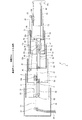
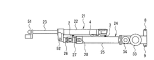
図1は、本発明に係る伸縮ブーム装置の一実施形態を説明する図である。なお、この伸縮ブーム装置は、油圧クレーンに用いられる例であり、同図は伸縮ブーム装置を全伸長した状態での側面図であり、複数のブームについては縦断面を図示している。
同図に示すように、この伸縮ブーム装置1は、複数のブーム10〜16と、それら複数のブームを伸縮する伸縮機構とを備えて構成されている。ここで、本実施形態は、七段の入れ子型をなす例であって、基端側(同図左側)の大きなブームから順に、基端ブーム10、第一中間ブーム11、第二中間ブーム12、第三中間ブーム13、第四中間ブーム14、第五中間ブーム15および先端ブーム16が、順次摺動自在に嵌挿されている。そして、これら複数のブーム10〜16が、第一および第二の伸縮手段を有する伸縮機構の作動に応じて伸縮されるようになっている。
Hereinafter, an embodiment of the present invention will be described with reference to the drawings as appropriate.
FIG. 1 is a view for explaining an embodiment of the telescopic boom device according to the present invention. This telescopic boom device is an example used for a hydraulic crane, and the figure is a side view of the telescopic boom device in a fully extended state, and a plurality of booms are shown in vertical section.
As shown in the figure, the
以下、その伸縮機構について説明する。
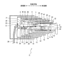
伸縮機構の第一の伸縮手段は、図1に示すように、複数のブーム内部に配設された二つのテレシリンダ21、24を有している。
これら二本のテレシリンダ21、24は、複数のブーム10〜16の伸縮方向に沿って隣接して配置されている。そして、二本のテレシリンダ21、24のうち、第一のテレシリンダ21は、通常の油圧シリンダ同様に、一段のロッド23を有している。一方、第二のテレシリンダ24は、同軸に設けられた二段のロッドを有する多段シリンダになっている。なお、第一のテレシリンダ21のロッド23の先端部には、二本のテレシリンダ21、24に連通する圧油給排管路29が付設されており、この圧油給排管路29によって、二本のテレシリンダ21、24の各ロッドの伸縮に必要な圧油が給排されるようになっている。
Hereinafter, the expansion / contraction mechanism will be described.
As shown in FIG. 1, the first telescopic means of the telescopic mechanism has two
These two
より詳しくは、第一のテレシリンダ21は、そのロッド23の先端が、基端ブーム10に第一連結ピン51によって枢支され、また、そのチューブ22の先端が、第二のテレシリンダ24のロッド先端側となる第一ロッド26の先端とともに、第一中間ブーム11に第二連結ピン52によって枢支されている。これにより、この第一のテレシリンダ21は、そのロッド23の伸縮に応じて、基端ブーム10に対して基端側から二段目の第一中間ブーム11を伸縮可能になっている。なお、この第一テレシリンダ21は、伸縮ブーム装置1が吊り荷の荷重によって「しなる」場合にも、第一連結ピン51を軸にして、第一テレシリンダ21が回動可能になっている。そのため、複数のブーム10〜16のしなり力を第一テレシリンダ21が受けることが防止されている。
More specifically, in the
一方、第二のテレシリンダ24は、同軸に設けられた二段のロッドを有する複動形テレスコピックシリンダであって、その構造はロッド内が二重構造をなしており、二段のロッド26、27を個々に伸縮可能に構成されている。そして、これら二段のロッドのうち、チューブ側の第二ロッド27は、第二中間ブーム12に、第三連結ピン53によって枢支されている。これにより、第一ロッド26を伸縮することによって、基端側から三段目の第二中間ブーム12が伸縮されるようになっている。さらに、この第二テレシリンダ24は、そのチューブ25先端のグランド部28が、第四連結ピン54によって四段目の第三中間ブーム13にトラニオン形式に枢支されており、これにより、第二ロッド27の伸縮によって四段目の第三中間ブーム13を伸縮させるようになっている。
On the other hand, the
なお、この第二テレシリンダ24には、そのチューブ25の尾端(伸縮方向の先端側)に、二つのガイドローラ8、9が設けられている。これら二つのガイドローラ8、9は、複数のブーム10〜16の伸縮方向に沿って移動するときに、内径が最も狭い先端ブーム16内において、その先端ブーム16内を第二テレシリンダ24が滑らかにスライド移動できるように、先端ブーム16内部の上下を案内しつつ転動するように設けられている。
ここで、この第二のテレシリンダ24は、その第一ロッド26先端の上面に且つ第一のテレシリンダ21側に、伸縮方向に沿って回転する第一ローラ2が設けられている。また、第一テレシリンダ21の尾端には、そのチューブ22尾端の下面に且つ第二のテレシリンダ24側に、伸縮方向に沿って回転する第三ローラ3が設けられている。
The
Here, the
さらに、前記第一のテレシリンダ21は、そのチューブ22下面に、第一ローラ2に当接する楔形のスロープ4が設けられている。このスロープ4は、第一ローラ2が当接する面が、第一ローラ2が乗り上げることによって、隣接して配置されている二本のテレシリンダ21、24相互の伸縮作動時の干渉を防止するような傾斜面になっている。また、上記のように付設されている第一ローラ2は、二本のテレシリンダ21、24のロッド伸長させたときに、支持脚(支点)として第一テレシリンダ21および第二のテレシリンダ24相互を支えるようになっている。
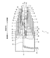
そして、上記第二の伸縮手段は、二つのテレシリンダ21、24のうち、上述した第二テレシリンダ24の伸縮作動に連動するように、複数のシーブ31〜36およびワイヤロープ41〜45を組み合わせてなる伸長用の手段、および縮小用の手段から構成されている。
Further, the
And the said 2nd expansion-contraction means combines several sheaves 31-36 and wire ropes 41-45 so that it may interlock | cooperate with the expansion / contraction operation | movement of the 2nd tele-
詳しくは、第二の伸縮手段のうち伸長用の手段としては、第二テレシリンダ24のチューブ25先端の側面に第三シーブ33が枢支されている。そして、この第三シーブ33に、第一ワイヤ41が掛け回されており、この第一ワイヤ41は、その一端が第二中間ブーム12の基端部12sに止着され、他端が第四中間ブーム14の基端部14sに止着されている。これにより、チューブ25の移動に伴う第三シーブ33の先端方向への移動に応じて第一ワイヤ41が牽引されると、第四中間ブーム14が第三中間ブーム13の伸長と同時に伸長されるようになっている。
Specifically, as a means for extension of the second telescopic means, a
さらに、第五中間ブーム15には、その基端上面部15sに第二ワイヤ42の一端が止着され、他端が、第四中間ブーム14の先端上面の第一シーブ31を介し、第三中間ブーム13の先端上面部13kに止着されている。また、先端ブーム16の基端上面部16kには、第三ワイヤ43の一端が止着され、他端が、第五中間ブーム15の基端上面に連結されている第二シーブ32を介し、第四中間ブーム14の先端上面部14kに止着されている。これにより、第三中間ブーム13が第二テレシリンダ24の第二ロッド27の伸長によって伸長されると、これに伴って第二ワイヤ42が第五中間ブーム15を牽引するとともに、第三ワイヤ43が先端ブーム16を牽引する。したがって、第五中間ブーム15および先端ブーム16が同時に伸長するようになっている。
Furthermore, one end of the
一方、第二の伸縮手段のうち縮小用の手段としては、第五シーブ35が、第四中間ブーム14の側面に枢支されており、また、第四シーブ34が、第二テレシリンダ24のチューブ25側面に枢支されている。そして、第四ワイヤ44は、その一端が、第四中間ブーム14の止着部14kに止着され、その止着部14kから第四シーブ34、第五シーブ35をS字状に掛け回してから、先端ブーム16の先端下面部16sに連結されている。これにより、第二テレシリンダ24の第二ロッド27の縮小に連動して、この第四ワイヤ44が牽引されることによって先端ブーム16を縮小させるようになっている。また、これと同時に、第五中間ブーム15は、先端ブーム16の基端上面部16kに止着されている第三ワイヤ43の張力によって縮小されるようになっている。
On the other hand, as a means for contraction of the second expansion / contraction means, the
また、第三中間ブーム13には、その基端部に第六シーブ36が枢支されている。そして、第五ワイヤ45の一端が、第二中間ブーム12の先端部12kに止着され、他端が第六シーブ36を介して、第四中間ブーム14の基端部14sに止着されている。これにより、第三中間ブーム13の縮小に連動して、第五ワイヤ45が牽引されることによって、第四中間ブーム14が縮小するようになっている。
上述の構成により、この第二の伸縮手段は、第二テレシリンダ24の第二ロッド27の伸縮作動に連動してワイヤロープ41〜45の張力を利用して複数のブーム10〜16のうち、先端側の所定のブームとして、第四中間ブーム14、第五中間ブーム15および先端ブーム16全部を同時に伸縮させるようになっている。
A
With the above-described configuration, the second expansion / contraction means uses the tension of the
次に、この伸縮ブーム装置1の動作、および作用・効果について図1〜図7を適宜参照しつつ説明する。
この伸縮ブーム装置1は、図3および4に示す全縮小した状態から伸長されるときは、まず、図6に示すように、第一テレシリンダ21のロッド23が伸長され、これにより、図5に示すように、基端ブーム10内から第一中間ブーム11が突出することによって、各中間ブーム11〜15および先端ブーム16全体が基端ブーム10内から張り出す。
次に、図8に示すように、第二テレシリンダ24の第一ロッド26が伸長され、第三ロッド27およびチューブ25がブーム先端側にスライド移動していく。これにより、図7に示すように、第一中間ブーム11内から第二中間ブーム12が突出することによって、中間ブーム12〜15および先端ブーム16全体が第一中間ブーム11内から張り出す。
Next, the operation | movement of this
When the
Next, as shown in FIG. 8, the
ここで、第一ロッド26が完全に伸長する前の状態において、図8(a)、(b)に示すように、第二ロッド27先端の上面に設けた第一ローラ2は、第一テレシリンダ21のチューブ22下面に設けたスロープ4に乗り上げるが、このスロープ4は、隣接して配置されている二本のテレシリンダ21、24相互の伸縮作動時の干渉を防止するような傾斜面になっているので、第一ローラ2がスロープ4の斜面上を移動すると、徐々に第一テレシリンダ21と第二テレシリンダ24とは離間していく。これにより、第一ロッド26が伸長を終えるときに、第一テレシリンダ21尾端の第三ローラ3は、第二テレシリンダ24のグランド部28に当接せず、グランド部28を避けるように第一テレシリンダ21の尾端を持ち上げることができる。
Here, in the state before the
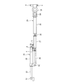
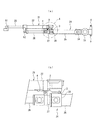
次に、図2に示すように、第二テレシリンダ24の第二ロッド27を伸長すると、図1に示すように、第二中間ブーム12内から第三中間ブーム13が突出することによって、中間ブーム13〜15および先端ブーム16全体が第二中間ブーム12内から張り出していく。さらに、第三中間ブーム13の伸長に伴って、上述したように、第二の伸縮手段は、第二テレシリンダ24の第二ロッド27の伸縮作動に連動して第四中間ブーム14、第五中間ブーム15および先端ブーム16全部を同時に伸長させ、これにより、複数のブーム10〜16が全伸長する。
Next, as shown in FIG. 2, when the
このとき、上記第一ローラ2は、支持脚にもなっているので、第一テレシリンダ21は、第二テレシリンダ24側の第一ローラ2にて持ち上げられた状態のまま支持される。そのため、第二テレシリンダ24の第二ロッド27の伸長開始時において、第一テレシリンダ21が第二テレシリンダ24に干渉することはない。また、第二ロッド27の縮小時においても、その縮小終端で、第二ローラ3がグランド部28に当接して乗り越えていくといったことも防止されている。
At this time, since the
なお、図1および2に示す全伸長した状態から縮小するときは、上記伸長する手順とは逆の手順によって二本のテレシリンダ21、24を縮小することによって複数のブーム10〜16全体を縮小することができる。
ここで、この伸縮ブーム装置1によれば、第一の伸縮手段は、複数のブーム10〜16を伸縮するための二本のテレシリンダ21、24が伸縮する方向に沿って隣接して配置されているので、本実施形態のように、複数のブーム10〜16の段数を七段にしても、ワイヤの掛け回しの複雑さを抑えつつブームを長尺にすることが可能である。
In addition, when reducing from the fully extended state shown in FIGS. 1 and 2, the
Here, according to the
そして、この伸縮ブーム装置1によれば、第二のテレシリンダ24の第二ロッド27先端の上面に且つ第一のテレシリンダ21側に、伸縮方向に沿って回転する第一ローラ2が設けられ、また、第一のテレシリンダ21のチューブ22下面には、第一ローラ2に当接するスロープ4が設けられており、このスロープ4は、第一ローラ2が乗り上げることによって、隣接して配置されている二本のテレシリンダ21、24相互の伸縮作動時の干渉を防止するような傾斜面になっているので、第一テレシリンダ21のスロープ4を転動することで第一テレシリンダ21をスロープ4に沿って僅かに持ち上げ、これにより、第二テレシリンダ24のグランド部28に当接しないようにすることができる。したがって、二本のテレシリンダ21、24相互の伸縮作動時の干渉を防止することができる。また、二本のテレシリンダ21、24の各ロッド伸長させたときに、付設した第一ローラ2を支持脚(支点)としているので、二本のテレシリンダ21、24の伸縮動作をより円滑にすることができる。
なお、本発明に係る伸縮ブーム装置は、上記実施形態に限定されるものではなく、本発明の趣旨を逸脱しなければ種々の変形が可能であることは勿論である。
According to the
It should be noted that the telescopic boom device according to the present invention is not limited to the above-described embodiment, and it goes without saying that various modifications can be made without departing from the spirit of the present invention.
1 伸縮ブーム装置
2 第一ローラ
3 第二ローラ
4 スロープ
8、9 ガイドローラ
10 基端ブーム
11 第一中間ブーム(二段目のブーム)
12 第二中間ブーム(三段目のブーム)
13 第三中間ブーム(四段目のブーム)
14 第四中間ブーム
15 第五中間ブーム
16 先端ブーム
21 第一テレシリンダ
22 チューブ
23 ロッド
24 第二テレシリンダ
25 チューブ
26 第一ロッド
27 第二ロッド
28 グランド部
29 圧油給排管路
31 第一シーブ
32 第二シーブ
33 第三シーブ
34 第四シーブ
35 第五シーブ
36 第六シーブ
41 第一ワイヤ
42 第二ワイヤ
43 第三ワイヤ
44 第四ワイヤ
45 第五ワイヤ
51 第一連結ピン
52 第二連結ピン
53 第三連結ピン
54 第四連結ピン
DESCRIPTION OF
12 Second intermediate boom (third boom)
13 Third intermediate boom (fourth boom)
14
Claims (1)
前記第一の伸縮手段は、二本のテレシリンダを有し、これら二本のテレシリンダが前記複数のブームの伸縮方向に沿って隣接して配置されており、第一のテレシリンダは、基端側の基端ブームに対して基端側から二段目のブームを伸縮し、第二のテレシリンダは、同軸に設けられた二段のロッドを有し、これら二段のロッドのうち、第一のロッドの伸縮によって基端側から三段目のブームを伸縮し、第二のロッドの伸縮によって四段目のブームを伸縮するとともに、前記第二の伸縮手段を連動させて五段目以降の他のブーム全部を同時に伸縮するようになっており、
前記第二のテレシリンダは、その第二のロッド先端の上面に且つ前記第一のテレシリンダ側に、前記伸縮方向に沿って回転するローラが設けられており、前記第一のテレシリンダは、そのチューブ下面に、前記ローラに当接するスロープが設けられており、当該スロープは、前記ローラが乗り上げることによって前記隣接して配置されている二本のテレシリンダ相互の伸縮作動時の干渉を防止するような傾斜面になっていることを特徴とする伸縮ブーム装置。 A plurality of booms that are slidably inserted from the base end side to the distal end side in turn, and a telescopic mechanism that expands and contracts the plurality of booms, and the telescopic mechanisms are disposed inside the plurality of booms. A first expansion / contraction means having a cylinder, and a second expansion / contraction means for expanding / contracting a predetermined boom among the plurality of booms using the tension of the wire rope in conjunction with the expansion / contraction operation of the first expansion / contraction means. A telescopic boom device comprising:
The first telescopic means has two telecylinders, and the two telecylinders are arranged adjacent to each other along the telescopic direction of the plurality of booms. The second boom is extended and retracted from the proximal side to the proximal boom on the end side, and the second telecylinder has a two-stage rod provided coaxially, and among these two-stage rods, The third stage boom is expanded and contracted from the base end side by the expansion and contraction of the first rod, the fourth stage boom is expanded and contracted by the expansion and contraction of the second rod, and the second expansion and contraction means is interlocked with the fifth stage. All other booms after that are designed to expand and contract at the same time ,
The second telecylinder is provided with a roller that rotates along the expansion and contraction direction on the upper surface of the second rod tip and on the first telecylinder side. A slope contacting the roller is provided on the lower surface of the tube, and the slope prevents the interference when the two tele-cylinders arranged adjacent to each other are extended and contracted when the roller rides up. The telescopic boom device is characterized by having such an inclined surface.
Priority Applications (1)
| Application Number | Priority Date | Filing Date | Title |
|---|---|---|---|
| JP2007339834A JP5154920B2 (en) | 2007-12-28 | 2007-12-28 | Telescopic boom device |
Applications Claiming Priority (1)
| Application Number | Priority Date | Filing Date | Title |
|---|---|---|---|
| JP2007339834A JP5154920B2 (en) | 2007-12-28 | 2007-12-28 | Telescopic boom device |
Publications (2)
| Publication Number | Publication Date |
|---|---|
| JP2009161272A JP2009161272A (en) | 2009-07-23 |
| JP5154920B2 true JP5154920B2 (en) | 2013-02-27 |
Family
ID=40964347
Family Applications (1)
| Application Number | Title | Priority Date | Filing Date |
|---|---|---|---|
| JP2007339834A Active JP5154920B2 (en) | 2007-12-28 | 2007-12-28 | Telescopic boom device |
Country Status (1)
| Country | Link |
|---|---|
| JP (1) | JP5154920B2 (en) |
Families Citing this family (8)
| Publication number | Priority date | Publication date | Assignee | Title |
|---|---|---|---|---|
| KR20130005470A (en) * | 2011-07-06 | 2013-01-16 | 동양기전 주식회사 | A driving device for crane boom assembly |
| CN102583174A (en) * | 2012-03-10 | 2012-07-18 | 安徽柳工起重机有限公司 | Crane boom |
| ITUB20160363A1 (en) * | 2016-01-29 | 2017-07-29 | Manitou Italia Srl | Telescopic arm for self-propelled operating machines. |
| CN107131193A (en) * | 2017-06-23 | 2017-09-05 | 南京快轮智能科技有限公司 | A kind of pneumatic telescopic rod |
| CN108750974A (en) * | 2018-07-13 | 2018-11-06 | 邹城市锦硕矿山设备科技有限公司 | A kind of section telescoping boom of parallel bars seven of crane |
| CN111217260A (en) * | 2018-11-26 | 2020-06-02 | 河南森源重工有限公司 | Crane knuckle arm and crane |
| CN115784048A (en) * | 2022-11-24 | 2023-03-14 | 沪东中华造船(集团)有限公司 | Telescopic davit |
| CN121019858A (en) * | 2025-10-30 | 2025-11-28 | 中国科学院沈阳自动化研究所 | A flexible solar panel extension mechanism |
Family Cites Families (3)
| Publication number | Priority date | Publication date | Assignee | Title |
|---|---|---|---|---|
| JPS6247595U (en) * | 1985-09-12 | 1987-03-24 | ||
| JPH0650460Y2 (en) * | 1986-10-28 | 1994-12-21 | 古河機械金属株式会社 | Boom telescope |
| JP2675400B2 (en) * | 1989-06-20 | 1997-11-12 | 古河機械金属株式会社 | Telescopic boom device |
-
2007
- 2007-12-28 JP JP2007339834A patent/JP5154920B2/en active Active
Also Published As
| Publication number | Publication date |
|---|---|
| JP2009161272A (en) | 2009-07-23 |
Similar Documents
| Publication | Publication Date | Title |
|---|---|---|
| JP5154920B2 (en) | Telescopic boom device | |
| CN104955763B (en) | Telescopic boom | |
| CN102878165B (en) | Telescopic boom and engineering machinery | |
| EP3805144A1 (en) | Crane | |
| CN103058077B (en) | Hoisting crane and crane arm thereof | |
| WO2015194268A1 (en) | Extension and retraction device for telescopic boom | |
| CN105417411A (en) | Telescopic boom structure based on multi-stage oil cylinder and crane | |
| JP6405880B2 (en) | Telescopic boom telescopic device | |
| CN202400760U (en) | Telescopic jib installations for cranes and cranes | |
| JP2006264797A (en) | Telescopic boom device | |
| US11111114B2 (en) | Expandable heavy equipment, elongated pull element, and use of expandable heavy equipment | |
| CN102126682A (en) | Single cylinder synchronous expansion and contraction device with multiple sets of inhaul cables for lorry-mounted crane | |
| US3419157A (en) | Booms having three sections, fully extensible with axially connected rams | |
| JP5154919B2 (en) | Cord reel device for telescopic boom device | |
| JPH0323195A (en) | Five-stage telescopic boom device | |
| CN205346686U (en) | Flexible arm structure and hoist with go back to mechanism of contracting | |
| CN105084231B (en) | Telescopic boom device and engineering machinery | |
| JPH11172919A (en) | Hose support device for concrete pump vehicle with boom | |
| JPH0323194A (en) | Telescopic boom device | |
| JP7654986B2 (en) | Backstop and crane equipped with same | |
| JP2004051366A (en) | Telescopic boom device | |
| JP6390058B2 (en) | Telescopic boom telescopic device | |
| JP2563999Y2 (en) | Multi-stage telescopic boom | |
| KR102942475B1 (en) | Telescopic boom | |
| JP6405879B2 (en) | Telescopic boom telescopic device |
Legal Events
| Date | Code | Title | Description |
|---|---|---|---|
| A625 | Written request for application examination (by other person) |
Free format text: JAPANESE INTERMEDIATE CODE: A625 Effective date: 20101006 |
|
| A977 | Report on retrieval |
Free format text: JAPANESE INTERMEDIATE CODE: A971007 Effective date: 20120905 |
|
| A131 | Notification of reasons for refusal |
Free format text: JAPANESE INTERMEDIATE CODE: A131 Effective date: 20120911 |
|
| A521 | Request for written amendment filed |
Free format text: JAPANESE INTERMEDIATE CODE: A523 Effective date: 20121102 |
|
| TRDD | Decision of grant or rejection written | ||
| A01 | Written decision to grant a patent or to grant a registration (utility model) |
Free format text: JAPANESE INTERMEDIATE CODE: A01 Effective date: 20121127 |
|
| A61 | First payment of annual fees (during grant procedure) |
Free format text: JAPANESE INTERMEDIATE CODE: A61 Effective date: 20121206 |
|
| FPAY | Renewal fee payment (event date is renewal date of database) |
Free format text: PAYMENT UNTIL: 20151214 Year of fee payment: 3 |
|
| R150 | Certificate of patent or registration of utility model |
Ref document number: 5154920 Country of ref document: JP Free format text: JAPANESE INTERMEDIATE CODE: R150 Free format text: JAPANESE INTERMEDIATE CODE: R150 |
|
| S531 | Written request for registration of change of domicile |
Free format text: JAPANESE INTERMEDIATE CODE: R313531 |
|
| R350 | Written notification of registration of transfer |
Free format text: JAPANESE INTERMEDIATE CODE: R350 |
|
| R250 | Receipt of annual fees |
Free format text: JAPANESE INTERMEDIATE CODE: R250 |
|
| R250 | Receipt of annual fees |
Free format text: JAPANESE INTERMEDIATE CODE: R250 |
|
| R250 | Receipt of annual fees |
Free format text: JAPANESE INTERMEDIATE CODE: R250 |
|
| R250 | Receipt of annual fees |
Free format text: JAPANESE INTERMEDIATE CODE: R250 |