JP5154919B2 - Cord reel device for telescopic boom device - Google Patents
Cord reel device for telescopic boom device Download PDFInfo
- Publication number
- JP5154919B2 JP5154919B2 JP2007339833A JP2007339833A JP5154919B2 JP 5154919 B2 JP5154919 B2 JP 5154919B2 JP 2007339833 A JP2007339833 A JP 2007339833A JP 2007339833 A JP2007339833 A JP 2007339833A JP 5154919 B2 JP5154919 B2 JP 5154919B2
- Authority
- JP
- Japan
- Prior art keywords
- boom
- cord reel
- wiring
- booms
- telescopic
- Prior art date
- Legal status (The legal status is an assumption and is not a legal conclusion. Google has not performed a legal analysis and makes no representation as to the accuracy of the status listed.)
- Active
Links
Images


Landscapes
- Jib Cranes (AREA)
Description
本発明は、基端ブームから先端ブームまでが順次伸縮自在に嵌挿された複数のブームを有する伸縮ブーム装置に用いられるコードリール装置に係り、特に、油圧クレーンの伸縮ブーム装置に好適に用い得て、配線の繰り出しおよび巻き取りが可能なコードリール本体を有するコードリール装置における、配線の取り回し、並びに取付け構造に関する。 The present invention relates to a cord reel device used in a telescopic boom device having a plurality of booms in which a base boom to a distal end boom are sequentially inserted and retracted, and can be suitably used particularly for a telescopic boom device of a hydraulic crane. In addition, the present invention relates to a wiring arrangement and a mounting structure in a cord reel device having a cord reel body capable of feeding and winding the wiring.
油圧クレーンは、伸縮可能な複数のブームを有する伸縮ブーム装置を備えている(例えば特許文献1参照)。ここで、この種の伸縮ブーム装置には、通常、コードリール装置が装備される。コードリール装置は、伸縮ブーム装置の先端に設けた作業ランプへの電源供給や、ワイヤの巻き過ぎを検出するための巻過検出器、吊荷の荷重測定のためのロードセル用の電源供給、およびこれら機器の信号伝達線等の必要な配線を、伸縮ブーム装置の伸縮に応じて繰り出しおよび巻き取りするために用いられる。 The hydraulic crane includes a telescopic boom device having a plurality of extendable booms (see, for example, Patent Document 1). Here, this type of telescopic boom device is usually equipped with a cord reel device. The cord reel device includes a power supply to a work lamp provided at the tip of the telescopic boom device, a winding detector for detecting excessive winding of the wire, a power supply for a load cell for measuring the load of the suspended load, and Necessary wiring such as signal transmission lines of these devices is used for feeding and winding in accordance with expansion and contraction of the telescopic boom device.
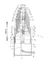
従来、この種のコードリール装置は、例えばクレーンのブーム段数が6段である場合、図7ないし図8に例示する伸縮ブーム装置100のコードリール装置102のように、コードリール本体4を先端ブーム16の先に設け、配線8を基端ブーム10の先端に設けた固定部3に固定するとともに基端ブーム10の上面のパイプ9内を貫通させ、さらに、不図示のコラムポストを経て旋回装置に設けたスリップリングに導き、最終的に車両のバッテリ等の電源に接続されている。
ところで、コードリール本体4内から引き出される配線8は、通常、基端ブーム10の先端部分に固定されている(図7(b)参照)。そのため、伸縮ブーム装置100を最も縮小した状態(図8参照)から最も伸長した状態(図7(a)参照)にした場合、実際のコードリール本体4内から引き出される配線8の必要長さは、図7ないし図8に示す6段ブームの場合ならば、5段分の長さに相当する配線が、コードリール本体4内に繰り出しおよび巻き取りされることになる。
By the way, the
そのため、伸縮ブーム装置の段数が一段増えると、例えば7段ブームであれば、引き出される配線の必要長さとして、6段分の長さに相当する配線を繰り出しおよび巻き取りする必要がある。つまり、7段ブームであれば、コードリール本体内に、伸縮ブーム装置を伸長した際に、6段相当以上の配線が内蔵されるものであれば、伸縮ブーム装置の伸縮にあわせて自在に繰り出しおよび巻き取りが行なえることになる。したがって、7段ブーム用にあわせて大型のコードリール本体を新しく設定すれば特に問題は生じない。 Therefore, when the number of stages of the telescopic boom device is increased by one, for example, in the case of a seven-stage boom, it is necessary to feed out and wind up the wiring corresponding to the length of six stages as the required length of the drawn-out wiring. In other words, if the boom is a seven-stage boom, when the telescopic boom device is extended in the cord reel body, it can be extended freely in accordance with the expansion and contraction of the telescopic boom device if wiring equivalent to six or more stages is built in. And you can take up. Therefore, there is no particular problem if a large cord reel body is newly set in accordance with the 7-stage boom.
しかしながら、7段式の伸縮ブーム装置であっても、6段式の伸縮ブーム装置用のコードリール本体を使用することができれば、コードリール本体を共用することができるため、製造コストや管理コストを削減することができる。
そこで、本発明は、このような問題点に着目してなされたものであって、伸縮ブーム装置の段数がN段式(例えば6段式)用のコードリール本体であっても、N+1段式(例えば7段式)にもそのコードリール本体を共用し得る伸縮ブーム装置用コードリール装置を提供することを目的としている。
However, even with a seven-stage telescopic boom device, if the cord reel main body for a six-stage telescopic boom device can be used, the cord reel main body can be shared. Can be reduced.
Therefore, the present invention has been made paying attention to such a problem, and even if the number of stages of the telescopic boom device is an N-stage type (for example, 6-stage type) cord reel body, an N + 1-stage type is provided. An object of the present invention is to provide a cord reel device for a telescopic boom device that can also share the cord reel body (for example, a seven-stage type).
上記課題を解決するために、本発明は、基端側の基端ブームから複数の中間ブームを介して入れ子状に接続された先端側の先端ブームまでが順次伸縮自在に嵌挿され、伸長時にはブーム基端側から順次伸長され、縮小時にはブームの先端側から順次縮小される複数のブームを有するとともに、前記複数の中間ブームのうち少なくとも前記基端ブームに最も近い第一中間ブームが単独で伸縮する伸縮ブーム装置に用いられ、前記基端ブームおよび先端ブームの間での配線の繰り出しおよび巻き取りが可能なコードリール装置であって、前記基端ブームに配設されて前記配線の先端を固定する固定部と、前記先端ブームに配設されて前記配線の繰り出しおよび巻き取りをするコードリール本体と、前記固定部およびコードリール本体の間に設けられて、前記配線を前記基端ブームと前記第一中間ブームとが嵌合する隙間に折り返しつつ前記コードリール本体への繰り出しおよび巻き取りを可能に支持する折り返し支持部と、を有することを特徴としている。 In order to solve the above-described problems, the present invention sequentially inserts from the proximal boom on the proximal end to the distal boom on the distal end connected in a nested manner via a plurality of intermediate booms, and is extended and retracted. It has a plurality of booms that are sequentially extended from the boom base end side and are sequentially reduced from the boom front end side at the time of reduction, and at least the first intermediate boom that is closest to the base boom among the plurality of intermediate booms is independently expanded and contracted A cord reel device that is used in a telescopic boom device that is capable of feeding and winding the wiring between the proximal boom and the distal boom, and is disposed on the proximal boom to fix the distal end of the wiring Provided between the fixing portion and the cord reel main body, the cord reel main body disposed on the tip boom for feeding and winding the wiring. Te, the wiring is characterized by having a folded supporting portion for supporting the feed and take-up to the cord reel body while folding the gap between the base end boom and the first intermediate boom is fitted Yes.
本発明に係る伸縮ブーム装置用コードリール装置によれば、配線の先端を固定する固定部と前記コードリール本体との間に、前記配線を折り返しつつコードリール本体への繰り出しおよび巻き取りを可能に支持する折り返し支持部を設けたので、この折り返し支持部によって、配線の長さを調節することができる。したがって、例えば伸縮ブーム装置の段数がN段式(例えば6段式)用のコードリール本体であっても、N+1段式(例えば7段式)にもそのコードリール本体を共用可能である。 According to the cord reel device for the telescopic boom device according to the present invention, it is possible to feed and wind the cord reel main body while folding the wiring between the fixing portion for fixing the tip of the wiring and the cord reel main body. Since the folding support part to support is provided, the length of wiring can be adjusted by this folding support part. Therefore, for example, even if the number of stages of the telescopic boom device is an N-stage type (for example, 6-stage type) cord reel body, the code reel body can be shared by N + 1-stage type (for example, 7-stage type).
つまり、このような構成であれば、実際にコードリール本体に巻き取るために必要な配線の長さは、コードリール本体の配線出口から固定部の先端までの長さであるから、この長さは、N段式(例えば6段式)のコードリールでの配線の長さと同じ長さとすることができる。そして、途中部分に配設した折り返し支持部は、配線を折り返しつつコードリール本体への繰り出しおよび巻き取りを可能に支持するので、この折り返し支持部によって、配線の長さをN+1段式(例えば7段式)にするために増える長さ分だけ調節することが可能である。したがって、例えば伸縮ブーム装置の段数がN段式(例えば6段式)用のコードリール本体であっても、N+1段式(例えば7段式)にもそのコードリール本体を共用化することが可能となる(なお、本明細書において、Nは2以上の自然数である)。 In other words, with such a configuration, the length of the wiring that is actually required for winding on the cord reel body is the length from the wiring outlet of the cord reel body to the tip of the fixed portion. Can be the same length as the wiring length of an N-stage (for example, 6-stage) cord reel. The folding support portion disposed in the middle portion supports the wire reel so that it can be fed out and taken up to the main body of the cord reel, so that the length of the wiring can be increased by N + 1 stages (for example, 7). It is possible to adjust by the increased length in order to obtain a step type). Therefore, for example, even if the number of stages of the telescopic boom device is an N-stage type (for example, 6-stage type) cord reel body, the code reel body can be shared in an N + 1-stage type (for example, 7-stage type). (In this specification, N is a natural number of 2 or more).
ここで、本発明に係る伸縮ブーム装置用コードリール装置において、前記折り返し支持部は、前記基端ブームに設けられる第一のケーブルローラと、前記基端側から二段目の前記第一中間ブームに設けられる第二のケーブルローラとを有し、前記コードリール本体からの配線が、前記第二のケーブルローラおよび第一のケーブルローラを順に掛け回した後に、前記固定部に固定されていると好ましい。このような構成であれば、基端側の基端ブームから順次または同時に伸長し、先端側の先端ブームから順次または同時に縮小する伸縮ブーム装置に、より好適に適用することができる。 Here, in the cord reel device for the telescopic boom device according to the present invention, the folding support portion includes a first cable roller provided on the base end boom and the first intermediate boom at the second stage from the base end side. A second cable roller provided on the cord reel, and the wiring from the cord reel body is fixed to the fixing portion after the second cable roller and the first cable roller are wound around in order. preferable. Such a configuration can be more suitably applied to a telescopic boom device that extends sequentially or simultaneously from the proximal boom on the proximal side and contracts sequentially or simultaneously from the distal boom on the distal side.
また、本発明に係る伸縮ブーム装置用コードリール装置において、前記コードリール本体は、前記伸縮ブーム装置の複数のブーム段数がN+1段のときに、N段に対応する配線の長さを最大巻き取り長さとするものであり、前記折り返し支持部で折り返される配線の長さを加えた配線の全長は、N+1段分に相当する長さであると好ましい。このような構成であれば、伸縮ブーム装置の段数がN段式(例えば6段式)用のコードリール本体であっても、N+1段式(例えば7段式)にもそのコードリール本体を共用する構成として好適である。 Further, in the cord reel device for the telescopic boom device according to the present invention, the cord reel body takes up the length of the wiring corresponding to the N-stage when the number of boom stages of the telescopic boom device is N + 1. The total length of the wiring including the length of the wiring folded back at the folding support portion is preferably a length corresponding to N + 1 stages. With such a configuration, even if the number of stages of the telescopic boom device is an N-stage type (for example, 6-stage type) cord reel body, the code reel body is also used for the N + 1-stage type (for example, 7-stage type). This configuration is suitable.
上述のように、本発明に係る伸縮ブーム装置用コードリール装置によれば、簡単な構成により、N段式のブームにおいて使用されるコードリール本体を、N+1段式の伸縮ブーム装置において共用化することができる。 As described above, according to the cord reel device for the telescopic boom device according to the present invention, the cord reel body used in the N-stage boom is shared in the N + 1-stage telescopic boom device with a simple configuration. be able to.
以下、本発明の一実施形態について、図面を適宜参照しつつ説明する。
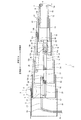
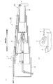
図1は、本発明に係る伸縮ブーム装置用コードリール装置を備える伸縮ブーム装置の一実施形態を説明する図であり、同図は伸縮ブーム装置を全伸長した状態での側面図であって、複数のブームについては縦断面を図示している。なお、上述した従来のコードリール装置を備える伸縮ブーム装置(6段式)と同様の構成については、同一の符号を付して説明する。
Hereinafter, an embodiment of the present invention will be described with reference to the drawings as appropriate.
FIG. 1 is a view for explaining an embodiment of a telescopic boom device including a cord reel device for a telescopic boom device according to the present invention, and FIG. 1 is a side view in a state where the telescopic boom device is fully extended, The longitudinal section is shown about a plurality of booms. In addition, the same code | symbol is attached | subjected and demonstrated about the structure similar to the telescopic boom apparatus (six-stage type) provided with the conventional cord reel apparatus mentioned above.
同図に示すように、この伸縮ブーム装置1は、複数のブーム10〜16と、それら複数のブームを伸縮する伸縮機構とを備えて構成されている。ここで、本実施形態は、七段の入れ子型をなす例であって、基端側(同図左側)の大きなブームから順に、基端ブーム10、第一中間ブーム11、第二中間ブーム12、第三中間ブーム13、第四中間ブーム14、第五中間ブーム15および先端ブーム16が、順次摺動自在に嵌挿されている。そして、これら複数のブーム10〜16が、第一および第二の伸縮手段を有する伸縮機構の作動に応じて伸縮されるようになっている。
As shown in the figure, the
以下、その伸縮機構について説明する。
この伸縮機構の第一の伸縮手段は、図1に示すように、複数のブーム内部に配設された二つのテレシリンダ21、24を有している。
これら二本のテレシリンダ21、24は、複数のブーム10〜16の伸縮方向に沿って隣接して配置されている。そして、二本のテレシリンダ21、24のうち、第一のテレシリンダ21は、通常の油圧シリンダ同様に、一段のロッド23を有している。一方、第二のテレシリンダ24は、同軸に設けられた二段のロッドを有する多段シリンダになっている。なお、第一のテレシリンダ21のロッド23の先端部には、二本のテレシリンダ21、24に連通する圧油給排管路29が付設されており、この圧油給排管路29によって、二本のテレシリンダ21、24の各ロッドの伸縮に必要な圧油が給排されるようになっている。
Hereinafter, the expansion / contraction mechanism will be described.
As shown in FIG. 1, the first expansion / contraction means of the expansion / contraction mechanism has two
These two
より詳しくは、第一のテレシリンダ21は、そのロッド23の先端が、基端ブーム10に第一連結ピン51によって枢支され、また、そのチューブ22の先端が、第二のテレシリンダ24のロッド先端側となる第一ロッド26の先端とともに、第一中間ブーム11に第二連結ピン52によって枢支されている。これにより、この第一のテレシリンダ21は、そのロッド23の伸縮に応じて、基端ブーム10に対して基端側から二段目の第一中間ブーム11を伸縮可能になっている。なお、この第一テレシリンダ21は、伸縮ブーム装置1が吊り荷の荷重によって「しなる」場合にも、第一連結ピン51を軸にして、第一テレシリンダ21が回動可能になっている。そのため、複数のブーム10〜16のしなり力を第一テレシリンダ21が受けることが防止されている。
More specifically, in the
一方、第二のテレシリンダ24は、同軸に設けられた二段のロッドを有する複動形テレスコピックシリンダであって、その構造はロッド内が二重構造をなしており、二段のロッド26、27を個々に伸縮可能に構成されている。そして、これら二段のロッドのうち、チューブ側の第二ロッド27は、第二中間ブーム12に、第三連結ピン53によって枢支されている。これにより、第一ロッド26を伸縮することによって、基端側から三段目の第二中間ブーム12が伸縮されるようになっている。さらに、この第二テレシリンダ24は、その第二ロッド27先端のグランド部28が、第四連結ピン54によって四段目の第三中間ブーム13にトラニオン形式に枢支されており、これにより、第二ロッド27の伸縮によって四段目の第三中間ブーム13を伸縮させるようになっている。
On the other hand, the
なお、この第二テレシリンダ24には、そのチューブ25の尾端(伸縮方向の先端側)に、二つのガイドローラ68、69が設けられている。これら二つのガイドローラ68、69は、複数のブーム10〜16の伸縮方向に沿って移動するときに、内径が最も狭い先端ブーム16内において、その先端ブーム16内を第二テレシリンダ24が滑らかにスライド移動できるように、先端ブーム16内部の上下を案内しつつ転動するように設けられている。
ここで、この第二のテレシリンダ24は、その第一ロッド26先端の上面に且つ第一のテレシリンダ21側に、伸縮方向に沿って回転する第一ローラ62が設けられている。また、第一テレシリンダ21の尾端には、そのチューブ22尾端の下面に且つ第二のテレシリンダ24側に、伸縮方向に沿って回転する第二ローラ63が設けられている。
The
Here, the
さらに、前記第一のテレシリンダ21は、そのチューブ22下面に、第一ローラ62に当接する楔形のスロープ64が設けられている。このスロープ64は、第一ローラ62が当接する面が、第一ローラ62が乗り上げることによって、隣接して配置されている二本のテレシリンダ21、24相互の伸縮作動時の干渉を防止するような傾斜面になっている。また、上記のように付設されている第一ローラ62は、二本のテレシリンダ21、24のロッド伸長させたときに、支持脚(支点)として第一テレシリンダ21および第二のテレシリンダ24相互を支えるようになっている。
Further, the
そして、上記第二の伸縮手段は、二つのテレシリンダ21、24のうち、上述した第二テレシリンダ24の伸縮作動に連動するように、複数のシーブ31〜36およびワイヤロープ41〜45を組み合わせてなる伸長用の手段、および縮小用の手段から構成されている。
詳しくは、第二の伸縮手段のうち伸長用の手段としては、第二テレシリンダ24のチューブ25先端の側面に第三シーブ33が枢支されている。そして、この第三シーブ33に、第一ワイヤ41が掛け回されており、この第一ワイヤ41は、その一端が第二中間ブーム12の基端部12sに止着され、他端が第四中間ブーム14の基端部14sに止着されている。これにより、チューブ25の移動に伴う第三シーブ33の先端方向への移動に応じて第一ワイヤ41が牽引されると、第四中間ブーム14が第三中間ブーム13の伸長と同時に伸長されるようになっている。
And the said 2nd expansion-contraction means combines several sheaves 31-36 and wire ropes 41-45 so that it may interlock | cooperate with the expansion / contraction operation | movement of the 2nd tele-
Specifically, as a means for extension of the second telescopic means, a
さらに、第五中間ブーム15には、その基端上面部15sに第二ワイヤ42の一端が止着され、他端が、第四中間ブーム14の先端上面の第一シーブ31を介し、第三中間ブーム13の先端上面部13kに止着されている。また、先端ブーム16の基端上面部16kには、第三ワイヤ43の一端が止着され、他端が、第五中間ブーム15の基端上面に連結されている第二シーブ32を介し、第四中間ブーム14の先端上面部14kに止着されている。これにより、第三中間ブーム13が第二テレシリンダ24の第二ロッド27の伸長によって伸長されると、これに伴って第二ワイヤ42が第五中間ブーム15を牽引するとともに、第三ワイヤ43が先端ブーム16を牽引する。したがって、第五中間ブーム15および先端ブーム16が同時に伸長するようになっている。
Furthermore, one end of the
一方、第二の伸縮手段のうち縮小用の手段としては、第五シーブ35が、第四中間ブーム14の側面に枢支されており、また、第四シーブ34が、第二テレシリンダ24のチューブ25側面に枢支されている。そして、第四ワイヤ44は、その一端が、第四中間ブーム14の止着部14kに止着され、その止着部14kから第四シーブ34、第五シーブ35をS字状に掛け回してから、先端ブーム16の先端下面部16sに連結されている。これにより、第二テレシリンダ24の第二ロッド27の縮小に連動して、この第四ワイヤ44が牽引されることによって先端ブーム16を縮小させるようになっている。また、これと同時に、第五中間ブーム15は、先端ブーム16の基端上面部16kに止着されている第三ワイヤ43の張力によって縮小されるようになっている。
On the other hand, as a means for contraction of the second expansion / contraction means, the
また、第三中間ブーム13には、その基端部に第六シーブ36が枢支されている。そして、第五ワイヤ45の一端が、第二中間ブーム12の先端部12kに止着され、他端が第六シーブ36を介して、第四中間ブーム14の基端部14sに止着されている。これにより、第三中間ブーム13の縮小に連動して、第五ワイヤ45が牽引されることによって、第四中間ブーム14が縮小するようになっている。
A
上述の構成により、この第二の伸縮手段は、第二テレシリンダ24の第二ロッド27の伸縮作動に連動してワイヤロープ41〜45の張力を利用して複数のブーム10〜16のうち、先端側の所定のブームとして、第四中間ブーム14、第五中間ブーム15および先端ブーム16全部を同時に伸縮させるようになっている。
さらに、この伸縮ブーム装置1には、コードリール装置2が付設されている。このコードリール装置2は、伸縮ブーム装置1の先端に設けた作業ランプ(不図示)への電源供給や、ワイヤの巻き過ぎを検出するための巻過検出器、吊荷の荷重測定のためのロードセル用の電源供給、およびこれら機器の信号伝達線等の必要な配線を、伸縮ブーム装置1の伸縮に応じて繰り出しおよび巻き取りするために用いられる。
With the above-described configuration, the second expansion / contraction means uses the tension of the
Further, a cord reel device 2 is attached to the
以下、コードリール装置2について、図1〜3を参照しつつ詳しく説明する。
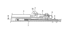
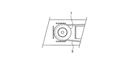
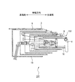
このコードリール装置2は、図1に示すように、固定部3、コードリール本体4、および折り返し支持部5を有して構成されている。固定部3は、基端ブーム10の先端側に配設されており、基端ブーム10外方に向けて立設された取付け用の金具である。この固定部3には、図2に拡大図示するように、配線8の先端を固定するための貫通孔3aが形成されている。
Hereinafter, the cord reel device 2 will be described in detail with reference to FIGS.
As shown in FIG. 1, the cord reel device 2 includes a fixed
コードリール本体4は、配線8の繰り出しおよび巻き取りをするものである。ここで、このコードリール本体4は、伸縮ブーム装置の複数のブーム段数がN+1段のときに、N段に対応する配線の長さを最大巻き取り長さとするものである。つまり、本実施形態の例では、伸縮ブーム装置1の複数のブーム10〜16の段数が7段であり、6段に対応する配線の長さを最大巻き取り長さとするものを用いている。そして、このコードリール本体4の取付け位置は、上記例示した、段数の一段少ない6段式の伸縮ブーム装置と同じ位置であり、コードリール本体4を先端ブーム16の先端部に設けている。
ここで、折り返し支持部5は、固定部3およびコードリール本体4の間に設けられており、配線(ケーブル)8を折り返しつつコードリール本体4への繰り出しおよび巻き取りを可能に支持するように構成されている。
The cord reel body 4 is used for feeding and winding the
Here, the folding back
詳しくは、この折り返し支持部5は、図1および図2に示すように、基端ブーム10の先端部の上面に、第一のケーブルローラ6を有し、基端側から二段目の第一中間ブーム11の基端部上面に、第二のケーブルローラ7を有している。第一のケーブルローラ6は、そのローラ表裏の面を垂直にして配設され、また、第二のケーブルローラ7は、そのローラ表裏の面を水平にして配設されている。そして、コードリール本体4からの配線8は、基端ブーム10と第一中間ブーム11とが嵌合する隙間に入り、第一中間ブーム11基端部の第二のケーブルローラ7に掛け回すことで折り返された後に、基端ブーム10先端から外部に再び出し、さらに、基端ブーム10先端のケーブルローラ6に掛け回した後に、固定部3の貫通孔3aに固定されている。
Specifically, as shown in FIGS. 1 and 2, the
つまり、複数のブーム10〜16が全縮小状態では、折り返し支持部5で折り返されている配線8の長さは、第一中間ブーム11の約二本分の長さとなり、この第一中間ブーム11の約二本分の長さの配線8が、折り返し支持部5によって、コードリール本体4への繰り出しおよび巻き取りを可能に支持されている。
そして、固定部3に固定された配線8は、配線8を保護するために設けられた基端ブーム10上面のパイプ9内を貫通して、以下不図示の、コラムポストを経て旋回装置に設けたスリップリングに導かれ、最終的に、車両側のバッテリ等の電源に接続されている。
That is, when the plurality of
And the
次に、この伸縮ブーム装置1およびコードリール装置2の作用・効果について図1〜図6を適宜参照しつつ説明する。
ところで、一般に、伸縮ブーム装置の伸縮は、移動式クレーン構造規格に規定されるように、伸長時にはブーム基端側から順次伸長させ、縮小時にはブームの先端側から順次縮小させなければならない。その理由は、入れ子式の伸縮ブーム装置では、基端側のブーム程その横断面積が大きくなり、断面係数も高くなるからである。
そのため、本実施形態の伸縮ブーム装置1においても、複数のブーム10〜16が全縮小した図4に示す状態から伸長されるときは、まず、図5に示すように、第一テレシリンダ21のロッド23が伸長され、これにより、基端ブーム10内から第一中間ブーム11が突出することによって、各中間ブーム11〜15および先端ブーム16全体が基端ブーム10内から張り出させている。
Next, operations and effects of the
By the way, in general, expansion and contraction of the telescopic boom device must be sequentially expanded from the boom base end side when extended, and sequentially contracted from the tip end side of the boom when contracted, as defined in the mobile crane structure standard. The reason is that, in the telescopic boom device of the telescoping type, the cross-sectional area of the boom on the base end side increases and the section modulus also increases.
Therefore, also in the
次に、図6に示すように、第二テレシリンダ24の第一ロッド26が伸長され、第三ロッド27およびチューブ25がブーム先端側にスライド移動していく。これにより、第一中間ブーム11内から第二中間ブーム12が突出することによって、中間ブーム12〜15および先端ブーム16全体が第一中間ブーム11内から張り出させる。
ここで、第一ロッド26が完全に伸長する前の状態において、第二ロッド27先端の上面に設けた第一ローラ62は、第一テレシリンダ21のチューブ22下面に設けたスロープ64に乗り上げるが、このスロープ64は、隣接して配置されている二本のテレシリンダ21、24相互の伸縮作動時の干渉を防止するような傾斜面になっているので、第一ローラ62がスロープ64の斜面上を移動すると、徐々に第一テレシリンダ21と第二テレシリンダ24とは離間していく。これにより、第一ロッド26が伸長を終えるときに、第一テレシリンダ21尾端の第二ローラ63は、第二テレシリンダ24のグランド部28に当接せず、グランド部28を避けるように第一テレシリンダ21の尾端を持ち上げることができる。
Next, as shown in FIG. 6, the
Here, in a state before the
次に、図1に示すように、第二テレシリンダ24の第二ロッド27を伸長すると、第二中間ブーム12内から第三中間ブーム13が突出することによって、中間ブーム13〜15および先端ブーム16全体が第二中間ブーム12内から張り出していく。さらに、第三中間ブーム13の伸長に伴って、上述したように、第二の伸縮手段は、第二テレシリンダ24の第二ロッド27の伸縮作動に連動して第四中間ブーム14、第五中間ブーム15および先端ブーム16全部を同時に伸長させ、これにより、複数のブーム10〜16が全伸長する。
Next, as shown in FIG. 1, when the
ここで、この伸縮ブーム装置1のコードリール装置2によれば、配線8の先端を固定する固定部3とコードリール本体4との間に、配線8を折り返しつつコードリール本体4への繰り出しおよび巻き取りを可能に支持する折り返し支持部5を設けたので、この折り返し支持部5によって、配線8の長さを調節することができる。
すなわち、複数のブーム10〜16が全縮小した図4に示す状態から伸長されるとき、折り返し支持部5で折り返されている配線8は、基端ブーム10の先端から第一のケーブルローラ6を介し、第一中間ブーム11の基端側に設けた第二のケーブルローラ7に掛け回した後、再び第一中間ブーム11の先端側へと折り返されて導かれているので、第一中間ブーム11の約二本分の長さが、コードリール本体4への繰り出しおよび巻き取りを可能に支持されているからである。
Here, according to the cord reel device 2 of the
That is, when the plurality of
ここで、この伸縮ブーム装置1は、上述のように、第一中間ブーム11が伸長するにつれ、基端ブーム10の先端と、第一中間ブーム11の基端部との距離は短くなる。つまり、このコードリール装置2において、基端ブーム10側の第一のケーブルローラ6と第一中間ブーム11側の第二のケーブルローラ7間の距離が縮まる。このとき、その縮まった距離分の余剰の配線8は、一旦、コードリール本体4内に巻き取られる。これは、折り返し支持部5が付設される第一中間ブーム11が、第一テレシリンダ21のロッド23によって単独で伸縮するためである。
Here, in the
その後、第二中間ブーム12〜先端ブーム16の伸長に伴い、コードリール本体4内の配線8は、複数のブーム10〜16が全伸長するのに応じて繰り出されていく。そのため、本実施形態の例のように、伸縮ブーム装置の段数が6段式用のコードリール本体4であっても、このコードリール装置2によれば、配線8の長さを折り返し支持部5によって第一中間ブーム11一段分の長さだけ調節することができる。したがって、7段式の伸縮ブーム装置1のコードリール本体として用いることを可能としている。
Thereafter, as the second
なお、図1に示す全伸長した状態から伸縮ブーム装置1を縮小するときは、上記伸長する手順とは逆の手順によって二本のテレシリンダ21、24を順次縮小することによって複数のブーム10〜16全体を縮小することができる。また、コードリール装置2についても、複数のブーム10〜16が縮小するときは、伸長時の逆の動作となる。
ここで、このコードリール装置2は、その折り返し支持部5が、基端ブーム10に設けられる第一のケーブルローラ6と、基端側から二段目の第一中間ブーム11に設けられる第二のケーブルローラ7とを有し、コードリール本体4からの配線8が、第二のケーブルローラ7および第一のケーブルローラ6を順に掛け回した後に、固定部3に固定されているので、基端側の基端ブーム10から順次または同時に伸長し、先端側の先端ブーム16から順次または同時に縮小する伸縮ブーム装置1に好適に適用することができる。
When the
Here, the cord reel device 2 includes a first cable roller 6 provided on the
つまり、例えば図1では、配線8が、コードリール本体4から最大に引き出された状態にある。このとき、もし仮に第一中間ブーム11を、先端側の他のブーム12〜16よりも先に基端ブーム10内に縮小しようとすれば、配線8が、コードリール本体4から更に引き出されようとすることになる。そのため、コードリール本体4が壊れてしまう。これに対し、先端側の他のブーム12〜16が先に縮小されていれば、このような問題は生じないからである。
なお、本発明に係る伸縮ブーム装置用コードリール装置は、上記実施形態に限定されるものではなく、本発明の趣旨を逸脱しなければ種々の変形が可能なことは勿論である。
That is, for example, in FIG. 1, the
It should be noted that the cord reel device for the telescopic boom device according to the present invention is not limited to the above embodiment, and it is needless to say that various modifications can be made without departing from the spirit of the present invention.
例えば、基端側の基端ブーム10から順次または同時に伸長し、先端側の先端ブーム16から順次または同時に縮小する伸縮ブーム装置1以外の構成とした場合であっても、当該伸縮ブーム装置での伸縮の順序に対応させて、適切な位置に折り返し支持部を配置することで、上記のようなコードリール本体4が壊れてしまう問題を回避することも可能である。しかし、上述のように、伸縮ブーム装置の伸縮順序は、移動式クレーン構造規格に規定されるように、一般に、伸長時にはブーム基端側から順次伸長させ、縮小時にはブームの先端側から順次縮小させなければならないため、本実施形態の折り返し支持部5の構成が、先端側の先端ブーム16から順次または同時に縮小する伸縮ブーム装置1において好適である。
For example, even when the
1 伸縮ブーム装置
2 コードリール装置
3 固定部
4 コードリール本体
5 折り返し支持部
6 第一のケーブルローラ
7 第二のケーブルローラ
8 配線
9 パイプ
10 基端ブーム
11 第一中間ブーム(二段目のブーム)
12 第二中間ブーム(三段目のブーム)
13 第三中間ブーム(四段目のブーム)
14 第四中間ブーム
15 第五中間ブーム
16 先端ブーム
21 第一テレシリンダ
22 チューブ
23 ロッド
24 第二テレシリンダ
25 チューブ
26 第一ロッド
27 第二ロッド
28 グランド部
29 圧油給排管路
31 第一シーブ
32 第二シーブ
33 第三シーブ
34 第四シーブ
35 第五シーブ
36 第六シーブ
41 第一ワイヤ
42 第二ワイヤ
43 第三ワイヤ
44 第四ワイヤ
45 第五ワイヤ
51 第一連結ピン
52 第二連結ピン
53 第三連結ピン
54 第四連結ピン
62 第一ローラ
63 第二ローラ
64 スロープ
68、69 ガイドローラ
DESCRIPTION OF
12 Second intermediate boom (third boom)
13 Third intermediate boom (fourth boom)
14
Claims (3)
前記基端ブームに配設されて前記配線の先端を固定する固定部と、前記先端ブームに配設されて前記配線の繰り出しおよび巻き取りをするコードリール本体と、前記固定部およびコードリール本体の間に設けられて、前記配線を前記基端ブームと前記第一中間ブームとが嵌合する隙間に折り返しつつ前記コードリール本体への繰り出しおよび巻き取りを可能に支持する折り返し支持部と、を有することを特徴とする伸縮ブーム装置用コードリール装置。 From the proximal boom on the proximal side to the distal boom on the distal side connected in a nested manner via a plurality of intermediate booms, the booms are sequentially extended and retracted. And a plurality of booms that are sequentially reduced from the distal end side, and at least a first intermediate boom that is closest to the base end boom among the plurality of intermediate booms is used in a telescopic boom device that independently expands and contracts. And a cord reel device capable of feeding and winding the wiring between the tip booms,
A fixing portion that is disposed on the base end boom and fixes the distal end of the wiring; a cord reel body that is disposed on the distal end boom and that feeds and winds the wiring; and the fixing portion and the cord reel body A folding support part provided between the base boom and the first intermediate boom to support the cord reel body so that the wiring can be fed and wound while being folded back. A cord reel device for a telescopic boom device.
Priority Applications (1)
| Application Number | Priority Date | Filing Date | Title |
|---|---|---|---|
| JP2007339833A JP5154919B2 (en) | 2007-12-28 | 2007-12-28 | Cord reel device for telescopic boom device |
Applications Claiming Priority (1)
| Application Number | Priority Date | Filing Date | Title |
|---|---|---|---|
| JP2007339833A JP5154919B2 (en) | 2007-12-28 | 2007-12-28 | Cord reel device for telescopic boom device |
Publications (2)
| Publication Number | Publication Date |
|---|---|
| JP2009161271A JP2009161271A (en) | 2009-07-23 |
| JP5154919B2 true JP5154919B2 (en) | 2013-02-27 |
Family
ID=40964346
Family Applications (1)
| Application Number | Title | Priority Date | Filing Date |
|---|---|---|---|
| JP2007339833A Active JP5154919B2 (en) | 2007-12-28 | 2007-12-28 | Cord reel device for telescopic boom device |
Country Status (1)
| Country | Link |
|---|---|
| JP (1) | JP5154919B2 (en) |
Families Citing this family (2)
| Publication number | Priority date | Publication date | Assignee | Title |
|---|---|---|---|---|
| JP5524007B2 (en) * | 2010-09-27 | 2014-06-18 | 住友重機械搬送システム株式会社 | Feed cable guide device |
| CN114560407A (en) * | 2022-02-22 | 2022-05-31 | 三一汽车起重机械有限公司 | Single-cylinder multi-section-arm telescopic mechanism, crane arm and crane |
Family Cites Families (5)
| Publication number | Priority date | Publication date | Assignee | Title |
|---|---|---|---|---|
| JPH0225833Y2 (en) * | 1984-12-01 | 1990-07-16 | ||
| JP2675400B2 (en) * | 1989-06-20 | 1997-11-12 | 古河機械金属株式会社 | Telescopic boom device |
| JPH0810587Y2 (en) * | 1989-08-24 | 1996-03-29 | 古河機械金属株式会社 | Crane rollover alarm device |
| JP2536079Y2 (en) * | 1992-03-25 | 1997-05-21 | 新明和工業株式会社 | Wire rope terminal attachment device for crane with overwind detector |
| JPH0663586U (en) * | 1993-02-17 | 1994-09-09 | 株式会社アイチコーポレーション | Assembly for built-in multi-stage telescopic boom |
-
2007
- 2007-12-28 JP JP2007339833A patent/JP5154919B2/en active Active
Also Published As
| Publication number | Publication date |
|---|---|
| JP2009161271A (en) | 2009-07-23 |
Similar Documents
| Publication | Publication Date | Title |
|---|---|---|
| US8661744B2 (en) | Telescoping mast | |
| JP5154920B2 (en) | Telescopic boom device | |
| WO2020026842A1 (en) | Crane | |
| JP6235854B2 (en) | Crane assembly method | |
| WO2015194268A1 (en) | Extension and retraction device for telescopic boom | |
| JP5154919B2 (en) | Cord reel device for telescopic boom device | |
| JP7287030B2 (en) | Telescopic cylinder assembly for telescopic boom | |
| CA3087450C (en) | Expandable heavy equipment, elongated pull element, and use of expandable heavy equipment | |
| JP5350896B2 (en) | Roughing jib assembly sheave device | |
| CN102126682A (en) | Single cylinder synchronous expansion and contraction device with multiple sets of inhaul cables for lorry-mounted crane | |
| JP2005082352A (en) | Tower crane | |
| JPH0323194A (en) | Telescopic boom device | |
| JPH0323195A (en) | Five-stage telescopic boom device | |
| CN105084231B (en) | Telescopic boom device and engineering machinery | |
| JP2001031374A (en) | Simultaneous telescoping mechanism of n-stage telescoping boom | |
| KR102134922B1 (en) | Small fire truck for lifesaving | |
| KR101850144B1 (en) | Aerial ladder include independence type extension boom | |
| JP4848094B2 (en) | Roughing jib equipment for self-propelled crane | |
| US12240739B2 (en) | System and method for increasing the load carrying capacity of a telescopic crane boom | |
| JP2563999Y2 (en) | Multi-stage telescopic boom | |
| JPH0840691A (en) | Jib housing device of crane | |
| JP2504606Y2 (en) | Multi-stage boom with hook parallel mechanism | |
| JPH04327496A (en) | Multi-stage retractable boom device | |
| JP2017057026A (en) | crane | |
| JPH04277225A (en) | Telescopic arm of construction machine used for both medium and large depth |
Legal Events
| Date | Code | Title | Description |
|---|---|---|---|
| A625 | Written request for application examination (by other person) |
Free format text: JAPANESE INTERMEDIATE CODE: A625 Effective date: 20101006 |
|
| A977 | Report on retrieval |
Free format text: JAPANESE INTERMEDIATE CODE: A971007 Effective date: 20120905 |
|
| A131 | Notification of reasons for refusal |
Free format text: JAPANESE INTERMEDIATE CODE: A131 Effective date: 20120911 |
|
| A521 | Request for written amendment filed |
Free format text: JAPANESE INTERMEDIATE CODE: A523 Effective date: 20121102 |
|
| TRDD | Decision of grant or rejection written | ||
| A01 | Written decision to grant a patent or to grant a registration (utility model) |
Free format text: JAPANESE INTERMEDIATE CODE: A01 Effective date: 20121127 |
|
| A61 | First payment of annual fees (during grant procedure) |
Free format text: JAPANESE INTERMEDIATE CODE: A61 Effective date: 20121206 |
|
| FPAY | Renewal fee payment (event date is renewal date of database) |
Free format text: PAYMENT UNTIL: 20151214 Year of fee payment: 3 |
|
| R150 | Certificate of patent or registration of utility model |
Ref document number: 5154919 Country of ref document: JP Free format text: JAPANESE INTERMEDIATE CODE: R150 Free format text: JAPANESE INTERMEDIATE CODE: R150 |
|
| S531 | Written request for registration of change of domicile |
Free format text: JAPANESE INTERMEDIATE CODE: R313531 |
|
| R350 | Written notification of registration of transfer |
Free format text: JAPANESE INTERMEDIATE CODE: R350 |
|
| R250 | Receipt of annual fees |
Free format text: JAPANESE INTERMEDIATE CODE: R250 |
|
| R250 | Receipt of annual fees |
Free format text: JAPANESE INTERMEDIATE CODE: R250 |
|
| R250 | Receipt of annual fees |
Free format text: JAPANESE INTERMEDIATE CODE: R250 |
|
| R250 | Receipt of annual fees |
Free format text: JAPANESE INTERMEDIATE CODE: R250 |