JP5149734B2 - COMMUNICATION DEVICE AND ITS CONTROL METHOD - Google Patents
COMMUNICATION DEVICE AND ITS CONTROL METHOD Download PDFInfo
- Publication number
- JP5149734B2 JP5149734B2 JP2008201191A JP2008201191A JP5149734B2 JP 5149734 B2 JP5149734 B2 JP 5149734B2 JP 2008201191 A JP2008201191 A JP 2008201191A JP 2008201191 A JP2008201191 A JP 2008201191A JP 5149734 B2 JP5149734 B2 JP 5149734B2
- Authority
- JP
- Japan
- Prior art keywords
- remote control
- communication
- setting
- connection
- camera
- Prior art date
- Legal status (The legal status is an assumption and is not a legal conclusion. Google has not performed a legal analysis and makes no representation as to the accuracy of the status listed.)
- Expired - Fee Related
Links
Images


Classifications
-
- H—ELECTRICITY
- H04—ELECTRIC COMMUNICATION TECHNIQUE
- H04B—TRANSMISSION
- H04B7/00—Radio transmission systems, i.e. using radiation field
- H04B7/24—Radio transmission systems, i.e. using radiation field for communication between two or more posts
-
- G—PHYSICS
- G03—PHOTOGRAPHY; CINEMATOGRAPHY; ANALOGOUS TECHNIQUES USING WAVES OTHER THAN OPTICAL WAVES; ELECTROGRAPHY; HOLOGRAPHY
- G03B—APPARATUS OR ARRANGEMENTS FOR TAKING PHOTOGRAPHS OR FOR PROJECTING OR VIEWING THEM; APPARATUS OR ARRANGEMENTS EMPLOYING ANALOGOUS TECHNIQUES USING WAVES OTHER THAN OPTICAL WAVES; ACCESSORIES THEREFOR
- G03B7/00—Control of exposure by setting shutters, diaphragms or filters, separately or conjointly
-
- G—PHYSICS
- G08—SIGNALLING
- G08C—TRANSMISSION SYSTEMS FOR MEASURED VALUES, CONTROL OR SIMILAR SIGNALS
- G08C17/00—Arrangements for transmitting signals characterised by the use of a wireless electrical link
-
- H—ELECTRICITY
- H04—ELECTRIC COMMUNICATION TECHNIQUE
- H04N—PICTORIAL COMMUNICATION, e.g. TELEVISION
- H04N21/00—Selective content distribution, e.g. interactive television or video on demand [VOD]
- H04N21/40—Client devices specifically adapted for the reception of or interaction with content, e.g. set-top-box [STB]; Operations thereof
- H04N21/41—Structure of client; Structure of client peripherals
- H04N21/4104—Peripherals receiving signals from specially adapted client devices
- H04N21/4113—PC
-
- H—ELECTRICITY
- H04—ELECTRIC COMMUNICATION TECHNIQUE
- H04N—PICTORIAL COMMUNICATION, e.g. TELEVISION
- H04N21/00—Selective content distribution, e.g. interactive television or video on demand [VOD]
- H04N21/40—Client devices specifically adapted for the reception of or interaction with content, e.g. set-top-box [STB]; Operations thereof
- H04N21/41—Structure of client; Structure of client peripherals
- H04N21/414—Specialised client platforms, e.g. receiver in car or embedded in a mobile appliance
- H04N21/4147—PVR [Personal Video Recorder]
-
- H—ELECTRICITY
- H04—ELECTRIC COMMUNICATION TECHNIQUE
- H04N—PICTORIAL COMMUNICATION, e.g. TELEVISION
- H04N21/00—Selective content distribution, e.g. interactive television or video on demand [VOD]
- H04N21/40—Client devices specifically adapted for the reception of or interaction with content, e.g. set-top-box [STB]; Operations thereof
- H04N21/41—Structure of client; Structure of client peripherals
- H04N21/422—Input-only peripherals, i.e. input devices connected to specially adapted client devices, e.g. global positioning system [GPS]
- H04N21/42204—User interfaces specially adapted for controlling a client device through a remote control device; Remote control devices therefor
-
- H—ELECTRICITY
- H04—ELECTRIC COMMUNICATION TECHNIQUE
- H04N—PICTORIAL COMMUNICATION, e.g. TELEVISION
- H04N21/00—Selective content distribution, e.g. interactive television or video on demand [VOD]
- H04N21/40—Client devices specifically adapted for the reception of or interaction with content, e.g. set-top-box [STB]; Operations thereof
- H04N21/43—Processing of content or additional data, e.g. demultiplexing additional data from a digital video stream; Elementary client operations, e.g. monitoring of home network or synchronising decoder's clock; Client middleware
- H04N21/436—Interfacing a local distribution network, e.g. communicating with another STB or one or more peripheral devices inside the home
- H04N21/4363—Adapting the video or multiplex stream to a specific local network, e.g. a IEEE 1394 or Bluetooth® network
- H04N21/43637—Adapting the video or multiplex stream to a specific local network, e.g. a IEEE 1394 or Bluetooth® network involving a wireless protocol, e.g. Bluetooth, RF or wireless LAN [IEEE 802.11]
-
- H—ELECTRICITY
- H04—ELECTRIC COMMUNICATION TECHNIQUE
- H04N—PICTORIAL COMMUNICATION, e.g. TELEVISION
- H04N23/00—Cameras or camera modules comprising electronic image sensors; Control thereof
- H04N23/60—Control of cameras or camera modules
- H04N23/63—Control of cameras or camera modules by using electronic viewfinders
- H04N23/631—Graphical user interfaces [GUI] specially adapted for controlling image capture or setting capture parameters
-
- H—ELECTRICITY
- H04—ELECTRIC COMMUNICATION TECHNIQUE
- H04N—PICTORIAL COMMUNICATION, e.g. TELEVISION
- H04N23/00—Cameras or camera modules comprising electronic image sensors; Control thereof
- H04N23/60—Control of cameras or camera modules
- H04N23/66—Remote control of cameras or camera parts, e.g. by remote control devices
- H04N23/661—Transmitting camera control signals through networks, e.g. control via the Internet
-
- H—ELECTRICITY
- H04—ELECTRIC COMMUNICATION TECHNIQUE
- H04N—PICTORIAL COMMUNICATION, e.g. TELEVISION
- H04N5/00—Details of television systems
- H04N5/76—Television signal recording
- H04N5/765—Interface circuits between an apparatus for recording and another apparatus
-
- H—ELECTRICITY
- H04—ELECTRIC COMMUNICATION TECHNIQUE
- H04N—PICTORIAL COMMUNICATION, e.g. TELEVISION
- H04N5/00—Details of television systems
- H04N5/76—Television signal recording
- H04N5/765—Interface circuits between an apparatus for recording and another apparatus
- H04N5/77—Interface circuits between an apparatus for recording and another apparatus between a recording apparatus and a television camera
Description
本発明は、通信装置及びその制御方法に関し、特には外部機器と近接無線通信が可能な通信装置及びその制御方法に関する。 The present invention relates to a communication device and a control method thereof, and more particularly, to a communication device capable of close proximity wireless communication with an external device and a control method thereof.
近年、数cm〜数十cmの通信可能範囲を有する近接無線通信技術を利用したシステムの開発が行われている。近接無線通信は、転送速度が高速で、かつ通信可能範囲が短いため他の無線システムへ影響を与えにくいという特徴を有するため、近接配置可能な機器間での無線データ通信に適している。 In recent years, a system using a proximity wireless communication technology having a communicable range of several centimeters to several tens of centimeters has been developed. Proximity wireless communication is suitable for wireless data communication between devices that can be placed close to each other because it has a high transfer rate and a short communication range and thus hardly affects other wireless systems.
例えば、アンテナを内蔵したカードをリーダライタに近接させると、リーダライタからカードに対して情報の読み出し及び書き込みが可能な非接触媒体処理装置が知られている(特許文献1)。 For example, there is known a non-contact medium processing apparatus capable of reading and writing information from a reader / writer to a card when a card incorporating an antenna is brought close to the reader / writer (Patent Document 1).
また、現在ではカードだけではなく、携帯電話などの通信端末においても、同様の非接触データ通信機能を有するものが知られている。 At present, not only a card but also a communication terminal such as a mobile phone is known which has a similar non-contact data communication function.
しかしながら、従来の近接無線通信装置は、データ送信時などにおいて、ユーザが自分の機器を相手側装置に近接させた状態を保持したままボタン押下などの操作を行う必要があった。そのため、送信するデータを選択し、送信を指示するといった細かい操作を行うことが難しかった。 However, in the conventional proximity wireless communication device, it is necessary for the user to perform an operation such as pressing a button while keeping his / her device close to the counterpart device at the time of data transmission or the like. For this reason, it is difficult to perform detailed operations such as selecting data to be transmitted and instructing transmission.
このような問題を解決する方法として、近接無線通信機器を直接操作せず、例えばリモートコントローラ(以下「リモコン」)を用いて遠隔操作することが考えられる。しかしながら、遠隔操作可能な機器は、一般的にリモコンによる操作を受け付けるか否かを設定可能である。そのため、ユーザは近接無線通信を行おうとする度に、装置のリモコン設定を確認し、さらに、リモコンによる操作を受け付けるよう必要に応じて設定を変更する操作を行わなければならず、煩雑であった。 As a method for solving such a problem, it is conceivable that the proximity wireless communication device is not directly operated, but is remotely operated using, for example, a remote controller (hereinafter referred to as “remote controller”). However, a device that can be remotely operated can generally set whether or not to accept an operation by a remote controller. Therefore, every time the user tries to perform close proximity wireless communication, the user has to confirm the remote controller setting of the apparatus, and further perform an operation to change the setting as necessary so as to accept the operation by the remote controller. .
本発明はこのような従来技術の課題に鑑みなされたものであり、近接無線通信の通信可能範囲内に保持しながらのユーザ操作を容易にすることが可能な通信装置及びその制御方法を提供することをその1目的とする。 The present invention has been made in view of the above-described problems of the prior art, and provides a communication device and a control method thereof that can facilitate user operation while being held within a communicable range of close proximity wireless communication. That is the purpose.
上述の目的は、近接無線通信により外部機器と通信するための通信手段と、リモコンから送信されるリモコン信号を受信する受信手段と、リモコンによる操作を許可するか禁止するかのリモコン設定を記憶する記憶手段と、通信手段を通じて、外部機器と近接無線通信による接続が確立しているか切断されているかを判別する判別手段と、判別手段により接続が確立していると判別された場合には、リモコン設定にかかわらず、受信手段が受信したリモコン信号に応じた動作を実行する制御手段とを有することを特徴とする通信装置によって達成される。 The purpose described above is to store communication means for communicating with an external device by proximity wireless communication, reception means for receiving a remote control signal transmitted from the remote control, and remote control settings for whether the operation by the remote control is permitted or prohibited. storage means through the communication means, if it is discriminated discriminating means for discriminating whether it is disconnected or connected through close-proximity wireless communication with the external device is established, the connection Ri by the discriminating means has been established Regardless of the remote control setting, this is achieved by a communication device characterized by having a control means for executing an operation according to a remote control signal received by the receiving means.
また、上述の目的は、近接無線通信により外部機器と通信するための通信手段と、リモコンから送信されるリモコン信号を受信する受信手段と、リモコンによる操作を許可するか禁止するかのリモコン設定を記憶する記憶手段と、通信手段を通じて、外部機器と近接無線通信による接続が確立しているか切断されているかを判別する判別手段と、判別手段により接続が確立していると判別された場合、リモコン設定がリモコンによる操作を禁止する設定であれば、リモコンによる操作を許可する設定に変更する変更手段と、リモコン設定がリモコンによる操作を許可する設定の場合に受信手段が受信したリモコン信号に応じた動作を制御する制御手段とを有することを特徴とする通信装置によっても達成される。 In addition, the above-mentioned object is to set communication means for communicating with an external device by proximity wireless communication, receiving means for receiving a remote control signal transmitted from the remote control, and remote control setting for permitting or prohibiting operation by the remote control. a storage storing means, via the communication means, if it is discriminated discriminating means for discriminating whether it is disconnected or connected through close-proximity wireless communication with the external device is established, the connection Ri by the discriminating means has been established If the remote control setting is a setting for prohibiting operation by the remote control, the changing means for changing to the setting for allowing the operation by the remote control and the remote control signal received by the receiving means when the remote control setting is the setting for allowing the operation by the remote control It is also achieved by a communication device having a control means for controlling the corresponding operation.
このような構成により、本発明によれば、通信装置を近接無線通信の通信可能範囲内に保持しながら容易に操作すること可能となる。 With such a configuration, according to the present invention, the communication device can be easily operated while being held within the communicable range of the close proximity wireless communication.
<第1の実施形態>
以下、図面を参照して、本発明をその好適かつ例示的な実施形態に基づいて詳細に説明する。
<First Embodiment>
Hereinafter, the present invention will be described in detail based on preferred and exemplary embodiments with reference to the drawings.
本実施形態は、デジタルカメラ(以後、カメラと呼ぶ)から画像データをストレージ装置に近接無線通信を用いて送信するシステムについて説明する。しかし、これらはそれぞれ、近接無線通信可能な通信装置、データ及び近接無線通信可能な外部機器の一例であり、本発明は本実施形態で説明する装置及びデータの特定の組み合わせに限定されない。 In the present embodiment, a system for transmitting image data from a digital camera (hereinafter referred to as a camera) to a storage apparatus using proximity wireless communication will be described. However, each of these is an example of a communication device that can perform near field communication, data, and an external device that can perform near field communication, and the present invention is not limited to a specific combination of the device and data described in the present embodiment.
なお、本明細書において、「近接無線通信」とは、通信距離が1m未満、特には数10cm未満であることを想定して規定された通信プロトコルに基づく無線通信を意味するものとする。このような通信プロトコルとしては、通信距離が約70cm以下の「近傍型」、同約10cm以下の「近接型」非接触通信プロトコルが知られている。具体的には、ISO/IEC 15693、ISO/IEC 14434、ECMA-340 (ISO/IEC 18092)などの規格が存在する。 In the present specification, “proximity wireless communication” means wireless communication based on a communication protocol defined on the assumption that the communication distance is less than 1 m, particularly less than several tens of centimeters. As such a communication protocol, a “neighboring type” non-contact communication protocol having a communication distance of about 70 cm or less and a “proximity type” non-contact communication protocol having a communication distance of about 10 cm or less are known. Specifically, standards such as ISO / IEC 15693, ISO / IEC 14434, and ECMA-340 (ISO / IEC 18092) exist.
図10は、本実施形態の通信システムの使用状態を模式的に示す図である。
システムは、近接無線通信可能なカメラ100と、カメラ100を遠隔操作するためのリモコン111と、クレードルとして機能するストレージ装置109を有する。近接無線通信可能なストレージ装置109は、例えばハードディスクドライブなどの記憶媒体1091を内蔵し、カメラ100から近接無線通信により受信した画像データを、記憶媒体1091に保存可能である。ストレージ装置109はまた、パーソナルコンピュータ(PC)200と例えばケーブルにより接続され、PC200からの制御を受けて動作することが可能である。
FIG. 10 is a diagram schematically illustrating a usage state of the communication system according to the present embodiment.
The system includes a
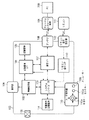
図1は、本実施形態の通信システムの構成例を示すブロック図である。
カメラ100はカメラ全体の動作を制御するシステムコントローラ101と、各機能を処理するブロックから構成される。システムコントローラ101は例えば制御プログラムを記憶する不揮発性記憶媒体と、制御プログラムを実行するCPUと、CPUがワークエリア等として用いるRAMとを備える。撮像部102は、例えばオートフォーカス機能とズーム機能を有する光学系と、その制御用モータ、CCDイメージセンサ及びCMOSイメージセンサなどの撮像素子などから構成される。撮像部102は、撮像素子の撮像面に被写体光学像を結像し、撮像素子により被写体光学像を画素単位の電気信号に変換して出力する。電気信号は画像処理部103によりデジタルデータに変換される。また、画像処理部103は、カメラの設定に応じて、デジタルデータに画像処理を行い、画像データファイルを生成する。画像データファイルは記録媒体インタフェース104を経由して半導体メモリなどの記録媒体105に記録される。
FIG. 1 is a block diagram illustrating a configuration example of a communication system according to the present embodiment.
The
また、記録媒体105に記録された画像データファイルを再生する際には、記録媒体105から読み出した画像データファイルに対して画像処理部103で表示用の処理を行った後、システムコントローラ101の制御に従って表示部106に表示する。図1において記録媒体105はカメラ100に内蔵されているものとするが、例えばメモリカードのように取り外し可能な記録媒体であってもよい。
When the image data file recorded on the
表示部106は例えばLCDであり、メニュー画面のような各種GUIや、記録媒体105に記録された画像などを表示する。撮像部102で撮像された画像を連続的に表示することで、電子ビューファインダとして機能させることも可能である。
The
通信インタフェース107は、アンテナ108を通じて外部機器と近接無線通信の接続及び切断を行う。また、通信インタフェース107は、確立された通信接続を用いて、外部機器との間でデータ通信を行う。
PC200も、カメラ100と同様の構成、例えばCPU、RAM、記憶媒体、通信インタフェースなどを含む。
なお、カメラ100の制御は、1つのハードウェアにより行ってもよいし、複数のハードウェアが役割分担しながら協働して処理を実行することで、結果としてカメラ全体を制御するよう機能してもよい。これはPC200の制御でも同様である。
The
The PC 200 includes the same configuration as the
Note that the
本実施形態のシステムにおいては、カメラ100とストレージ装置109とは、相互通信が可能であるものとする。従って、カメラ100の記録媒体105に記録された画像データをストレージ装置109へ送信して保存することも、ストレージ装置109に保存されている画像データをカメラ100へ送信して記録媒体105に記録することも可能である。
In the system of the present embodiment, it is assumed that the
ユーザ操作部110は、ユーザがカメラ100に対して指示を与えるための指示部材である。ユーザ操作部110の操作はシステムコントローラ101に通知され、システムコントローラ101はユーザ操作部110の操作に応じた動作を実現するようにカメラ100の各部を制御する。本実施形態において、ユーザ操作部110は方向キーやカーソルキーとも呼ばれる十字キー110aと、決定キーや実行キーとも呼ばれるセットキー110bと、メニューキー110cとを含んでいる。
The
また、上述のようにカメラ100は、リモコン111による遠隔操作を受け付けることが可能である。リモコン111から発せられた信号(例えば赤外線信号)は、リモコン信号受信部112で受信され、リモコン信号インタフェース113を経由してシステムコントローラ101に入力される。システムコントローラ101はリモコン111の操作に応じた動作を実現するようにカメラ100の各部を制御する。リモコン信号(遠隔操作)を受け付けるか否かの設定(リモコン設定)は、後述するように、ユーザ操作部110を通じたメニュー操作によってユーザが行うことができる。
Further, as described above, the
リモコン111にはカメラ100のユーザ操作部110に準ずる操作キーが設けられている。遠隔操作の受け付け可否の設定内容は、例えば不揮発性記憶媒体114に記憶され、設定の変更があった場合に記憶内容が変更される。
The
(接続検知処理)
次に、図2に示すシーケンスチャートを参照して、カメラ100による、ストレージ装置109との接続検知処理について説明する。
なお、図2に示す通信手順は、カメラ100とストレージ装置109との役割を入れ替えてもよいため、接続要求を送信する機器を機器A、接続要求に応答する機器を機器Bとして一般的な近接無線通信の手順として説明する。
(Connection detection processing)
Next, with reference to a sequence chart shown in FIG. 2, a connection detection process with the
In the communication procedure shown in FIG. 2, since the roles of the
近接無線通信を行うには、機器Aのアンテナと機器Bのアンテナが予め定められた近距離(以下、「通信可能範囲」)内にある必要がある。機器Aから接続要求を出す場合、図2(a)に示すように、機器Bのアンテナが通信可能範囲外にあれば、機器Bは接続要求(S201)を受信できず、当然、接続要求に対する機器Bの応答が無いため、接続が確立しない。 In order to perform close proximity wireless communication, the antenna of the device A and the antenna of the device B need to be within a predetermined short distance (hereinafter referred to as “communicable range”). When a connection request is issued from the device A, as shown in FIG. 2A, if the antenna of the device B is outside the communicable range, the device B cannot receive the connection request (S201). Since there is no response from device B, the connection is not established.
機器Aと機器Bのアンテナ間の距離(以下、単に機器Aと機器Bの距離、という場合には、アンテナ間の距離を意味する)が通信可能範囲内に近接している場合、機器間での接続確立処理が行われる。 When the distance between the antennas of device A and device B (hereinafter simply referred to as the distance between device A and device B means the distance between the antennas) is close within the communicable range, The connection establishment process is performed.
機器Aと機器Bが近接して通信可能範囲内に入ったときに通信接続を確立し、通信可能範囲を超えて離間するまで接続状態を維持するシステムにおいて、機器Aから機器Bに接続要求を出す場合の接続処理手順を(図2(b))に示す。 In a system that establishes a communication connection when device A and device B enter the communicable range close to each other, and maintains the connection state until the device A and B are separated beyond the communicable range, a connection request is sent from device A to device B. The connection processing procedure in the case of putting out is shown in FIG. 2 (b).
機器Aからの接続要求(S201)に対し、機器Bから接続を受け付ける応答(S202)が返信されると、接続が確立される。機器Aと機器Bの接続は、両者が接続可能範囲内に位置する場合には、機器Aから接続解除要求(S205)が送信され、機器Bからの接続解除応答(S206)が受信されるまで維持される。 In response to the connection request from the device A (S201), when a response (S202) for accepting the connection is returned from the device B, the connection is established. When both devices A and B are located within the connectable range, a connection release request (S205) is transmitted from device A and a connection release response (S206) from device B is received. Maintained.
このシステムでは、定期的に機器Aから接続監視要求(S203)を送信して接続状態を監視する必要がある。機器Aからの接続監視要求(S203)に対して機器Bからの接続確認応答(S204)が受信されれば接続状態、接続確認応答が無ければ接続解除状態である。一旦接続が確立してから、機器Aと機器Bとの距離が通信可能範囲を超えた場合、接続監視要求(S203)に対する応答が無くなるため、応答受信のタイムアウト処理として、機器Aにおいて接続解除処理が行われる。 In this system, it is necessary to periodically monitor the connection state by transmitting a connection monitoring request (S203) from the device A. If the connection confirmation response (S204) from the device B is received in response to the connection monitoring request (S203) from the device A, the connection state is established. If there is no connection confirmation response, the connection is released. Once the connection is established, if the distance between the device A and the device B exceeds the communicable range, there is no response to the connection monitoring request (S203). Is done.
データ送受信の度に接続、切断を行うシステムにおける機器Aと機器Bの接続確認手順を図2(c)に示す。機器Aから接続要求(S201)を送信し、機器Bからの接続を受け付ける応答(S202)を受け取ることによって接続状態が確認できる。図2(c)に示す例では、データ送受信を伴わないため、接続状態を確認した後、機器Aから接続解除要求(S205)を送信し、接続を解除させている。 FIG. 2C shows a procedure for confirming the connection between the devices A and B in the system that connects and disconnects each time data is transmitted and received. The connection state can be confirmed by transmitting a connection request (S201) from the device A and receiving a response (S202) for accepting a connection from the device B. In the example shown in FIG. 2C, since data transmission / reception is not involved, after confirming the connection state, a connection release request (S205) is transmitted from the device A to release the connection.
なお、ここでは、機器Aと機器Bとの接続確立の確認を無線通信の成立に基づいて行う場合を説明したが、通信電波強度や機械的なスイッチの状態に基づいて接続確立の確認を行うこともできる。 Although the case where confirmation of connection establishment between the device A and the device B is performed based on establishment of wireless communication has been described here, the connection establishment is confirmed based on communication radio wave intensity or a mechanical switch state. You can also.
(データ通信処理)
次に、図3に示すシーケンスチャートを参照して、カメラ100とストレージ装置109との間のデータ通信処理を説明する。
なお、図3に示す通信手順も、カメラ100とストレージ装置109との役割を入れ替えて実施可能であるため、要求を送信する機器を機器A、要求に応答する機器を機器Bとして一般的な近接無線通信の手順として説明する。また、図3において、図2と同じ手順については同じ参照数字を付してある。
(Data communication processing)
Next, data communication processing between the
Note that the communication procedure shown in FIG. 3 can also be performed by exchanging the roles of the
図3(a)は、図2(b)で説明した、機器Aと機器Bが近接して通信可能範囲内に入ったときに通信接続を確立し、通信可能範囲を超えて離間するまで接続状態を維持するシステムにおけるデータ送信処理の手順を示す。 FIG. 3 (a) establishes a communication connection when device A and device B approach each other within the communicable range, as described in FIG. 2 (b), and connects until the communicable range is exceeded. The procedure of the data transmission process in the system which maintains a state is shown.
機器Aがデータ送信要求を送信する(S301)と、機器Bはデータ受信準備処理を行い、機器Aに受信準備完了の応答を返す(S302)。この応答を受け取ると機器Aは、データを機器Bに送信する(S303)。そして、データ送信が終了すると、送信終了を機器Bに通知する(S305)。この通知を機器Bが受け取ると、受信終了を機器Aに送信して(S306)、データ送信処理は終了する。 When device A transmits a data transmission request (S301), device B performs a data reception preparation process and returns a reception preparation completion response to device A (S302). Upon receiving this response, device A transmits data to device B (S303). Then, when the data transmission is completed, the transmission completion is notified to the device B (S305). When device B receives this notification, it transmits a reception end to device A (S306), and the data transmission process ends.
機器Bから機器Aにデータ送信する(機器Aが機器Bからデータを受信する)場合の処理の手順を(図3(b))に示す。
機器Aは機器Bに対して受信要求を送信する(S307)。機器Bはこの要求に対して送信準備を行い、送信準備完了の応答を返す(S308)。この応答を受け取ると機器Aは、受信準備を行い、受信準備完了を機器Bに通知する(S309)。機器Bは、受信準備完了の通知を受信すると、データを機器Aに送信する(S310)。そして、データ送信が終了すると、送信終了を機器Aに通知する(S312)。この通知を機器Aが受け取ると、受信終了を機器Bに送信して(S313)、データ受信処理は終了する。
FIG. 3B shows a processing procedure when data is transmitted from the device B to the device A (the device A receives data from the device B).
The device A transmits a reception request to the device B (S307). In response to this request, device B prepares for transmission and returns a response indicating completion of transmission preparation (S308). Upon receiving this response, device A prepares for reception and notifies device B that reception preparation is complete (S309). Upon receipt of the reception preparation completion notification, device B transmits data to device A (S310). When the data transmission is completed, the transmission completion is notified to the device A (S312). When device A receives this notification, it sends a reception end to device B (S313), and the data reception process ends.
図2(c)に示した、データ送受信の度に接続、切断するシステムにおける、データ送信処理の手順を図3(c)に、またデータ受信処理の手順を図3(d)にそれぞれ示す。図3(c)及び(d)から明らかなように、データ送受信の処理手順は、図3(a)及び(b)で説明した通りである。そして、データ送受信処理の前後、図2(c)で説明したに接続処理と接続解除処理が行われる。 FIG. 3C shows a data transmission processing procedure and FIG. 3D shows a data reception processing procedure in the system shown in FIG. As is clear from FIGS. 3C and 3D, the data transmission / reception processing procedure is as described in FIGS. 3A and 3B. Then, before and after the data transmission / reception process, the connection process and the connection release process are performed as described with reference to FIG.
なお、データ送受信処理でやりとりされるデータの内容は、画像データのような情報に限らず、機器を制御するためのコマンドであってもよい。 The content of data exchanged in the data transmission / reception process is not limited to information such as image data, but may be a command for controlling the device.
(カメラ100のGUI)
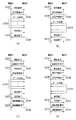
本実施形態のカメラ100において、データ送受信に係る操作のために表示部106に表示するGUI画面の例を図4を用いて説明する。
カメラ100の動作モードが再生モードにある状態でメニューキー110cが押下されると、システムコントローラ101は、再生モードのメニュー画面(図4(a))を表示部106に表示させる。なお、GUI画面のデータは、システムコントローラ101内の不揮発性記憶媒体又は、不揮発性記憶媒体114に予め記憶されているものとする。
(
In the
When the menu key 110c is pressed while the operation mode of the
メニュー画面中の項目の中から、「無線通信」が選択された状態でセットキー110bが押下されると、システムコントローラ101は無線通信メニュー画面(図4(b))を表示部106に表示させる。
When the set key 110b is pressed while “wireless communication” is selected from the items on the menu screen, the
本実施形態において無線通信メニューの項目は3つあり、1枚表示されている画像を送る「画像送信モード」、サムネイル表示画面から送りたい画像を選択して一括送信する「選択送信モード」、外部機器内の画像を受信する「画像受信モード」がある。 In this embodiment, there are three items of the wireless communication menu, “image transmission mode” for sending one image displayed, “selective transmission mode” for selecting images to be sent from the thumbnail display screen, and external transmission, There is an “image reception mode” for receiving images in the device.
図4(c)は、無線通信メニュー画面から「画像送信」が選択され、セットキー110bが押下された際にシステムコントローラ101が表示部106に表示させる画像1枚再生画面の例を示す。画像1枚再生画面で表示される画像は、例えば記録媒体105に記録された画像のうち、撮影日時が最新のものなど、任意の条件もしくはユーザ設定に従ってシステムコントローラ101が決定することができる。
FIG. 4C shows an example of a single image playback screen that the
画像1枚再生画面でセットキー110bが押下されると、システムコントローラ101は、表示中の画像に対応する画像データを記録媒体105から読み出し、通信インタフェース107を通じてストレージ装置109への送信を開始する。
When the
図4(d)は、画像1枚再生画面から送信を行っている間の画面表示例を示す。プログレスバー401により、送信処理の進行状況を表示している。送信が終了すると、システムコントローラ101はプログレスバー401を消去し、送信前の画面(図4(c))に戻す。
FIG. 4D shows a screen display example during transmission from the single image playback screen. A
システムコントローラ101は、例えば十字キー110aの左右キーの操作に応じて、画像1枚再生画面に表示する画像を切り替える。従って、ユーザは、十字キー110aを操作して所望の画像が表示される状態として、セットキー110cを押下することで、任意の画像を1枚ずつストレージ装置109に送信することができる。本実施形態において、ストレージ装置109は、受信した画像データを内部の記憶媒体に保存するものとする。
The
画像1枚再生画面でメニューキー110cが押下されると、システムコントローラ101は無線通信メニュー(図4(b))を表示部106に表示させる。なお、画像送信モードでは、静止画像データのみならず、動画像データや音声データを送信することもできる。例えば動画像データを送信する場合は、「画像送信モード」の画像1枚再生画面では、動画像ストリームの先頭フレームが表示される。この状態かもしくは再生中の一時停止状態でセットキー110bが押下されると、システムコントローラ101は、動画像データストリームの送信を開始する。なお、動画像データの送信には時間が掛かる場合があるため、送信中画面(図4(c))でセットキー110bが押下されると、システムコントローラ101は送信処理を中断する。
When the menu key 110c is pressed on the single image playback screen, the
図4(e)は、無線通信メニュー画面から「選択送信」が選択され、セットキー110bが押下された際にシステムコントローラ101が表示部106に表示させるサムネイル再生画面の例を示す。サムネイル再生画面で表示される画像は、例えば記録媒体105に記録された画像のうち、撮影日時が最新のものから所定枚数など、任意の条件もしくはユーザ設定に従ってシステムコントローラ101が決定することができる。
FIG. 4E shows an example of a thumbnail playback screen that the
ユーザは、サムネイル再生画面に表示されているサムネイル画像のうち、所望のものを選択状態にする。例えば、システムコントローラ101は、十字キー110aの操作に応じてカーソルを移動させ、セットキー110bが押下された際にカーソルが存在しているサムネイルを選択状態とする。図4(e)の例では、4つのサムネイル402が選択状態となっている状態を示している。
The user selects a desired one of the thumbnail images displayed on the thumbnail reproduction screen. For example, the
そして、システムコントローラ101は、セットキー110bが長押しされたことを検出すると、その時点で選択状態にあるサムネイル画像に対応した画像データの送信処理を開始する。
When the
図4(f)は、サムネイル再生画面から送信を行っている間の画面表示例を示す。プログレスバー403により、送信処理の進行状況を表示している。送信が終了すると、システムコントローラ101はプログレスバー403を消去し、送信前の画面(図4(e))に戻す。
FIG. 4F shows a screen display example during transmission from the thumbnail reproduction screen. A
なお、動画送信時と同様、送信中画面(図4(f))でセットキー110bが押下されると、システムコントローラ101は送信処理を中断する。
As in the case of moving image transmission, when the set key 110b is pressed on the transmission screen (FIG. 4 (f)), the
図4(g)は、無線通信メニュー画面から「画像受信」が選択され、セットキー110bが押下された際にシステムコントローラ101が表示部106に表示させる受信待ち画面の例を示す。
FIG. 4G shows an example of a reception waiting screen that the
本実施形態のカメラ100は、画像受信モードにおいて、(接続が確立されている)外部機器が再生している静止画像に対応する画像データを受信することが出来る。また、外部機器側で送信画像選択済の状態であれば、選択された画像に対応する画像データを一括で受信することが出来る。受信する画像が動画像である場合、外部機器で再生一時停止中の動画像データを受信することが出来る。また、外部機器でプレイリストを作成している場合は、プレイリストとプレイリストに含まれる動画像データを一括して受信することが出来る。
In the image reception mode, the
図4(h)は、外部機器からデータを受信している間の画面表示例を示す。プログレスバー404により、受信処理の進行状況を表示している。受信が終了すると、システムコントローラ101はプログレスバー404を消去し、受信前の画面(図4(g))に戻す。
なお、受信中画面(図4(h))でセットキー110bが押下されると、システムコントローラ101は受信処理を中断する。
FIG. 4H shows a screen display example while data is being received from an external device. A
When the set key 110b is pressed on the receiving screen (FIG. 4H), the
また、外部機器であるストレージ装置109に接続されたPC200も、図4(b)と同様の無線通信メニュー画面を表示し、ストレージ装置109のユーザに所望の無線通信処理を選択させることが可能である。
Further, the
PC200からストレージ装置109を制御する場合、ユーザは無線通信メニュー画面から「画像受信」を選択することで、ストレージ装置109をカメラ100からのデータを受信するモードに遷移させることができる。
When controlling the
PC200は、GUIベースのOSが稼働する汎用コンピュータ装置であってよく、表示装置に表示されたGUIの操作は、キーボードやマウスなどの一般的な入力装置を用いて行うことが可能である。PC200とストレージ装置109とは、例えばUSBやIEEE1394などの通信インタフェースを通じて接続することができる。
The
(遠隔操作設定)
次に、本実施形態のカメラ100におけるリモコン設定について説明する。
図5は、本実施形態のカメラ100において、リモコン設定に係る操作のために表示部106に表示するGUI画面の例を示す図である。図5(a)は、メニュー画面から「システム設定」が選択され、セットキー110bが押下された際にシステムコントローラ101が表示部106に表示させるシステム設定画面の例を示す。
(Remote operation setting)
Next, remote control setting in the
FIG. 5 is a diagram illustrating an example of a GUI screen displayed on the
さらに、システム設定画面から「リモコン信号設定」が選択され、セットキー110bが押下されると、システムコントローラ101は、リモコン信号設定画面(図5(b))を表示部106に表示させる。なお、外部機器であるストレージ装置109と近接無線通信による接続が確立された状態では、「リモコン信号設定」はグレーアウトされ、選択不可となる。
Further, when “remote control signal setting” is selected from the system setting screen and the set key 110b is pressed, the
図5(b)に示すリモコン信号設定画面から、「ON」が選択、決定されることにより、カメラ100がリモコン111から受信したリモコン信号による遠隔操作を受け付けるよう設定される。
When “ON” is selected and determined from the remote control signal setting screen shown in FIG. 5B, the
また、リモコン信号設定画面から「OFF」が選択、決定されると、リモコン禁止モードが設定され、カメラ100はリモコン111による遠隔操作を受け付けない。リモコン禁止モードは不特定多数のユーザが近距離で複数のカメラを使用する際に、他人の使用しているリモコンによって自分のカメラが誤動作するのを防止するためにある。
When “OFF” is selected and determined from the remote control signal setting screen, the remote control prohibit mode is set, and the
リモコン信号設定画面で設定された遠隔操作設定の内容はシステムコントローラ101によって不揮発性記憶媒体114に記憶され、カメラ100の電源が切られてもその値を保持している。
The content of the remote operation setting set on the remote control signal setting screen is stored in the
上述のように、リモコン111にも十字キー110a、セットキー110b及びメニューキー110cが設けられているため、リモコン操作が許可されていれば、図4及び図5で説明したGUI操作はリモコン111から行うこともできる。
As described above, the
(リモコン信号受信時の動作)
リモコン信号を受信した際のカメラ100の動作について、図6のフローチャートを用いて説明する。
リモコン信号インタフェース113を通じてリモコン信号の受信を検出すると、システムコントローラ101は、不揮発性記憶媒体114に記憶されたリモコン設定を確認する(S601)。システムコントローラ101は、リモコン設定が「ON」であれば(S602,YES)、受信したリモコン信号に応じた処理を実行するよう、カメラ100の各部を制御する(S603)。一方、リモコン設定が「OFF」であれば(S602,NO)、システムコントローラ101は、受信したリモコン信号を無視する。
(Operation when receiving remote control signal)
The operation of the
When the reception of the remote control signal is detected through the remote
(外部機器との通信接続・切断時のリモコン設定自動変更)
次に、本実施形態のカメラ100が、外部機器であるストレージ装置109との近接無線通信接続の確立時及び切断時に行うリモコン設定の自動変更処理について説明する。
(Automatic change of remote control settings when connecting / disconnecting with external devices)
Next, remote control setting automatic change processing performed when the
図7は、カメラ100がストレージ装置109との接続確立時に行うリモコン設定自動変更処理を説明するフローチャートである。
また、図8は、カメラ100がストレージ装置109との接続切断時に行うリモコン設定自動変更処理を説明するフローチャートである。
なお、図7及び図8に示す処理は、図2(b)で説明した、機器Aと機器Bとが通信可能範囲内に位置する間は常時接続を確立し続けるシステムを対象としたものである。
FIG. 7 is a flowchart for explaining remote control setting automatic change processing performed when the
FIG. 8 is a flowchart for explaining remote control setting automatic change processing performed when the
Note that the processing shown in FIG. 7 and FIG. 8 is intended for the system described in FIG. 2B, in which the connection is always established while the devices A and B are located within the communicable range. is there.
外部機器との近接無線通信による接続が確立していない間、カメラ100は図7に示す処理を行う。ここで、カメラ100の通信インタフェース107は、通信待機状態において、例えば図2(a)に示すように定期的に接続要求を送信し、近接無線通信可能な外部機器(ストレージ装置109)を探索しているものとする。そして、接続要求に対して接続を受け付ける応答を受信すると、ストレージ装置109と近接無線通信接続を確立する。
While the connection by the proximity wireless communication with the external device is not established, the
システムコントローラ101は、ストレージ装置109と近接無線通信による接続が確立するのを待機する(S701)。
The
ストレージ装置109との接続が確立すると、システムコントローラ101は、不揮発性記憶媒体114からリモコン設定を読み出し、設定内容を確認する(S702)。システムコントローラ101は、リモコン設定の内容を判別し(S703)、リモコン操作が許可されていれば(リモコン設定の内容が「ON」であれば)、リモコン設定を変更せずに処理を終了する。
When the connection with the
一方、S703において、リモコン操作が禁止されていれば(リモコン設定の内容が「OFF」であれば)、システムコントローラ101は、不揮発性記憶媒体114のリモコン設定をリモコン操作を許可する設定(「ON」)に変更する(S704)。
On the other hand, if remote control operation is prohibited in S703 (if the remote control setting is “OFF”), the
そして、システムコントローラ101は、元の設定を自動変更したことを示す情報として、変更フラグをセットする(S705)。具体的には、システムコントローラ101は、例えば不揮発性記憶媒体114の所定アドレスに、自動変更したことを表す所定の値(例えば”1”)を書き込む。変更フラグをセットしたら、システムコントローラ101は処理を終了する。
Then, the
一方、外部機器との近接無線通信による接続が確立している間、カメラ100は図8に示す処理を行う。
S801において、システムコントローラ101はストレージ装置109との近接無線通信による接続が切断されたか否かを監視する。図2(b)で説明したように、通信インタフェース107は、接続解除要求を送信するか、接続監視要求に対する応答がない場合、無線接続が切断されたと検知する。
On the other hand, while the connection by the close proximity wireless communication with the external device is established, the
In step S <b> 801, the
ストレージ装置109との無線接続が切断された場合、システムコントローラ101は不揮発性記憶媒体114の変更フラグがセットされているか否か判別する(S802)。変更フラグがセットされていた場合(S803,YES)には、無線接続の確立時にリモコン設定が自動変更されたことを示す。従って、システムコントローラ101は不揮発性記憶媒体114のリモコン設定を「OFF」に復帰させ(S804)、変更フラグをリセットする(S805)。具体的には、システムコントローラ101は、例えば不揮発性記憶媒体114の所定アドレスに、自動変更されていないことを表す所定の値(例えば”0”)を書き込む。変更フラグをリセットしたら、システムコントローラ101は処理を終了する。
When the wireless connection with the
変更フラグがセットされていない場合(S803,NO)は、無線接続の確立時にリモコン設定が変更されていないことを示すので、システムコントローラ101はリモコン設定及び変更フラグを変更せずに処理を終了する。
If the change flag is not set (S803, NO), it indicates that the remote control setting has not been changed when the wireless connection is established. Therefore, the
なお、図7、図8は、カメラ100がストレージ装置109との接続状態を監視するシステム(カメラ100が機器A、ストレージ装置109が機器Bとなるシステム)における処理を説明した。しかし、逆に、ストレージ装置109がカメラ100との接続状態を監視するシステム(カメラ100が機器B、ストレージ装置109が機器Aとなるシステム)でも同様の処理で対応可能である。この場合、ストレージ装置109から接続要求を受信した場合に、S701でシステムコントローラ101は接続の確立を検知する。また、ストレージ装置109から接続解除要求を受信した場合に、S801でシステムコントローラ101は接続の切断を検知する。
7 and 8 describe the processing in the system in which the
また、図2(c)で説明したような、データ送受信の度に無線接続を確立、切断するシステムの場合、カメラ100はリモコン信号の受信時に図9のフローチャートに示す処理を行う。図9において、図7、図8と同じ処理ステップについては同じ参照数字を付してある。
In the case of a system that establishes and disconnects a wireless connection every time data is transmitted and received as described with reference to FIG. 2C, the
システムコントローラ101は、リモコン信号を受信すると、その内容を一時的に例えば不揮発性記憶媒体114の所定アドレスに記憶する。そして、システムコントローラ101は、通信インタフェース107及びアンテナ108を通じて外部機器(ストレージ装置109)に接続要求を送信する(S901)。
Upon receiving the remote control signal, the
図2(c)で説明したように、接続要求に対してストレージ装置109から接続を受け付ける応答を受信すれば、ストレージ装置109と近接無線通信による接続が確立していることが確認される。
As described with reference to FIG. 2C, when a response for accepting a connection is received from the
ストレージ装置109との接続が確立していることが確認されると(S902,YES)と、システムコントローラ101はS702〜S705の処理を行う。そして、不揮発性記憶媒体114の所定アドレスに記憶した、受信リモコン信号の内容に応じた処理を実行するよう、カメラ100の各部を制御する(S905)。このS905の処理は、図6で説明したS601〜S603の処理に相当する。
When it is confirmed that the connection with the
一方、ストレージ装置109との接続が確立していることが確認されない場合(S902,NO)、システムコントローラ101はS802〜S804の処理を行う。そして、不揮発性記憶媒体114の所定アドレスに記憶した、受信リモコン信号の内容に応じた処理を実行するよう、カメラ100の各部を制御する(S905)。
On the other hand, when it is not confirmed that the connection with the
このように、本実施形態のカメラ100は、ストレージ装置109と近接無線通信による接続が確立している間は、リモコン操作を禁止する(受け付けない)状態に設定されている場合でも、自動的にリモコン操作を許可する(受け付ける)状態に変更する。
As described above, the
そのため、カメラ100をストレージ装置109の上に載せるなどして、近接無線通信の接続が確立した状態では、カメラ100における設定にかかわらず、カメラ100をリモコン111で操作することが可能になる。
Therefore, in a state in which the connection of the close proximity wireless communication is established by placing the
従って、ユーザは近接無線通信を行う毎にメニュー操作を行って現在のリモコン設定を確認したり、リモコン設定の内容を変更したりすることなしに、近接無線通信時にはリモコンを用いてカメラを操作することが可能となり、使い勝手がよい。 Therefore, the user operates the camera using the remote control during the close proximity wireless communication without performing the menu operation every time the close proximity wireless communication is performed and checking the current remote control setting or changing the content of the remote control setting. It becomes possible and is convenient.
また、近接無線通信による接続が確立されていることが確認された際にカメラをリモコン操作を許可する状態に変更した場合、接続の切断時にはリモコン操作を禁止する状態に復帰させれば、さらに使い勝手を改善することができる。 In addition, if it is confirmed that a connection by close proximity wireless communication is established, the camera is changed to a state in which remote control operation is permitted. Can be improved.
なお、本実施形態では、通信接続の確立が確認された際にリモコン設定を自動変更する場合、不揮発性記憶媒体114に記憶されたリモコン設定の内容自体を変更し、接続の切断後に設定内容を元に戻す処理を行った。しかし、必ずしも不揮発性記憶媒体114に記憶されているリモコン設定の内容を変更する必要はない。
In this embodiment, when the remote control setting is automatically changed when the establishment of the communication connection is confirmed, the content of the remote control setting stored in the
例えば、通信接続が確立していることが確認された際には、リモコン設定の内容にかかわらず、常にリモコン操作を受け付けてもよい。この場合、リモコン信号を受信したら、外部機器との接続が確立しているか確認し、確認できた場合にはリモコン信号に応じた処理を実行するようにすればよい。この場合、S702〜S705の処理や、S802〜S805の処理は不要である。 For example, when it is confirmed that a communication connection is established, a remote control operation may always be accepted regardless of the content of the remote control setting. In this case, when a remote control signal is received, it is confirmed whether a connection with an external device has been established, and if it is confirmed, processing corresponding to the remote control signal may be executed. In this case, the process of S702-S705 and the process of S802-S805 are unnecessary.
<第2の実施形態>
次に本発明の第2の実施形態について説明する。
近接無線通信は、第1の実施形態で説明したような、カメラとストレージ装置のように全く異なる機器間での通信だけでなく、例えばカメラとカメラのように、同種の機器間の通信にも用いることができる。
<Second Embodiment>
Next, a second embodiment of the present invention will be described.
Proximity wireless communication is not only for communication between completely different devices such as a camera and a storage device as described in the first embodiment, but also for communication between similar devices such as a camera and a camera. Can be used.
この場合、カメラが同一機種であったり、同一メーカの製品である場合のように、共通したリモコン信号で両者が動作しうる場合がある。例えば、同じ機種のカメラ同士が近接無線通信を行った場合について考える。この場合、例えばユーザが一方のカメラを操作しようとリモコンで指示を行っても、両者は近接しているため、リモコンの信号を両方のカメラが受信し、それぞれがリモコン信号に従った動作を行ってしまう可能性がある。 In this case, both cameras may operate with a common remote control signal, as in the case where the cameras are the same model or the products of the same manufacturer. For example, consider a case where cameras of the same model perform close proximity wireless communication. In this case, for example, even if the user gives an instruction to operate one of the cameras using the remote control, both cameras are close to each other, so both cameras receive the remote control signal, and each operates in accordance with the remote control signal. There is a possibility that.
そこで本実施形態では、仮に同一機種の機器が近接無線通信を行う場合であっても、その一方のみがリモコン信号に基づく動作を行うような仕組みを提供する。 Therefore, in the present embodiment, even if devices of the same model perform close proximity wireless communication, only one of them performs a mechanism based on a remote control signal.
図11は、本実施形態の通信システムの使用状態を模式的に示す図である。
機器A及び機器Bはそれぞれ近接無線通信可能な通信装置の一例としてのカメラ100及び100’であり、両者は例えば同一構成を有する機器であってよい。本実施形態では、機器Aがデータ送信側機器、機器Bがデータ受信側機器とする。また、リモコン111は、カメラ100及び100’に共通したリモコン信号を送信することが可能である。
FIG. 11 is a diagram schematically illustrating a usage state of the communication system of the present embodiment.
Device A and device B are
図12は、本実施形態の通信システムの構成例を示すブロック図である。
図12において、カメラ100は、第1の実施形態と共通した構成を有する。また、外部機器としてのカメラ100’は、カメラ100と同一構成を有するものとし、例えばシステムコントローラ101’はカメラ100’の構成要素である。なお、カメラ100、100’は、共通のリモコン信号で動作可能な任意の機器の組み合わせであってよい。
FIG. 12 is a block diagram illustrating a configuration example of a communication system according to the present embodiment.
In FIG. 12, the
図13及び図14は、本実施形態に係る機器A(カメラ100)及び機器B(カメラ100’)の動作を説明するフローチャートである。
図13に示す処理は、カメラ100がデータを近接無線通信によって送信する動作モードに指定された際に実行される。具体的には、図4(b)の無線通信メニューから、「画像送信」または「選択送信」が選択され、セットキー110bが押下された際に、図13の処理が開始される。同様に、図14に示す処理は、カメラ100’がデータを近接無線通信によって受信する動作モードに指定された際に実行される。具体的には、図4(b)の無線通信メニューから、「画像受信」が選択され、セットキー110bが押下された際に、図14の処理が開始される。
13 and 14 are flowcharts for explaining the operations of the device A (camera 100) and the device B (
The process shown in FIG. 13 is executed when the
S3001で、システムコントローラ101は、通信インタフェース107を通じて接続要求を送信する。
S3002で、システムコントローラ101は、S3001で送信した接続要求に対する応答(接続を受け付ける応答)を受信したか否か判別する。受信できない場合、システムコントローラ101は処理をS3001へ戻し、一定時間後、再度接続要求を送信する。
In step S3001, the
In step S3002, the
一方、接続要求に対して接続を受け付ける応答を受信した場合、システムコントローラ101は第1の実施形態において説明したS702〜S705の処理を行い、リモコン操作を禁止するリモコン設定であった場合にはリモコン操作を許可する設定に変更する。従って、少なくともこの時点以降は、リモコン111によってカメラ100を操作することが可能になる。
On the other hand, when a response for accepting a connection is received in response to the connection request, the
後述するように、受信側機器であるカメラ100’では、リモコン操作を禁止するリモコン設定になるような処理を行っているので、リモコン111の操作によってカメラ100及び100’の両方が動作することはない。
As will be described later, in the
次に、S3003で、システムコントローラ101は、操作可能状態であることを示すため、表示部106に操作カーソルの表示などを行う。システムコントローラ101は例えば、「画像送信モード」では、画像1枚再生画面(図4(c))を、「選択送信モード」では、サムネイル再生画面(図4(e))を表示させる。
In step S <b> 3003, the
S3004では、ユーザが所望の画像の選択などの操作を行う。この際、ユーザはユーザ操作部110を用いてもよいが、リモコン111を用いることで、カメラ100’との通信接続を保持しながら容易にカメラ100を操作することができる。
In S3004, the user performs an operation such as selecting a desired image. At this time, the user may use the
S3005で、システムコントローラ101は、ユーザが送信の実行を指示するまでの間、カメラ100’と定期的にステータス通知などのデータ通信を行い、カメラ100’に通信待機状態を維持するよう要求する。
In step S3005, the
S3006で、システムコントローラ101は、ユーザ操作が確定したか否か、すなわち、送信の実行が指示されたか否かの判定を行う。ユーザの操作が確定したと判定されれば処理をS3007へ進め、そうでなければ処理をS3004へ戻す。
In step S3006, the
本実施形態では、システムコントローラ101は、例えば「画像送信モード」では、画像1枚再生画面(図4(c))において、セットキー110bが押下され、送信の実行が指示されたことを検出したならば、操作が確定したと判定する。同様に「選択送信モード」では、サムネイル再生画面(図4(e))では、セットキー110bの長押しを検出すると操作が確定したと判定する。
In the present embodiment, for example, in the “image transmission mode”, the
S3007で、システムコントローラ101は、通信インタフェース107を通じて送信要求をカメラ100’に送信する。ここでは、指定された画像のデータ送信要求を送信する。これに対し、カメラ100’のシステムコントローラ101’は、要求を受け付ける応答を行う(S3110)。
In step S3007, the
この応答を受けて、システムコントローラ101はS3008で、データ送信処理を行う。ここでは、選択指定された1枚または複数枚の画像データを、記録媒体105から読み出し、通信インタフェース107を介してカメラ100’に送信する。
In response to this response, the
S3009で、システムコントローラ101は、通信終了か否かの判定を行う。通信終了の場合、システムコントローラ101’は、リモコン設定の復帰処理を行い(S3010)、処理を終了する。S3010における処理は、第1の実施形態におけるS802〜S805と同様の処理であってよい。通信終了でない場合には、再びS3004、およびS3005の処理に戻り同様の処理が繰り返される。
In step S3009, the
図14に移り、S3101で、システムコントローラ101’は、通信インタフェース107’を通じて接続要求を受信したか否かの判定を行う。接続要求が受信できない場合、システムコントローラ101’はS3101を繰り返し実行する。 Turning to FIG. 14, in S3101, the system controller 101 'determines whether a connection request has been received through the communication interface 107'. If the connection request cannot be received, the system controller 101 'repeatedly executes S3101.
カメラ100及び100’が通信可能範囲内に近接し、接続要求が受信できたら、S3102でシステムコントローラ101’は、不揮発性記憶媒体114’に記憶されたリモコン設定を確認する。
When the
S3103で、システムコントローラ101’は、S3102で取得したリモコン設定が、リモコン操作を許可する設定(「ON」)か、禁止する設定(「OFF」)かを判別する。リモコン操作を禁止する設定の場合、受信側機器であるカメラ100’はすでにリモコンによる操作を受け付けないため、システムコントローラ101’はリモコン設定を変更せずに処理をS3105へ進める。一方、リモコン操作を許可する設定であれば、カメラ100の操作を意図したリモコン111の操作によりカメラ100’が動作することを防止するため、システムコントローラ101’はS3104で、リモコン設定を変更する。すなわち、システムコントローラ101’は、不揮発性記憶媒体114’のリモコン設定を、リモコン操作を禁止する設定(「OFF」)に変更する。そして、システムコントローラ101’は、元の設定を自動変更したことを示す情報として、第1の実施形態と同様にして変更フラグをセットする(S3105)。
In step S <b> 3103, the
S3106で、システムコントローラ101’は、S3101で受信した接続要求に対する応答を返す。なお、S3101からS3106までの、接続要求を受信してから接続を受け付ける応答を返すまでの処理時間(T2とする)は、接続要求元であるカメラ100(S3002)で応答なしと判定されるまでの時間(T1とする)よりも短い(T1>T2)ものとする。しかし、S3102〜S3105の処理に時間を要し、T1≦T2となる場合には、接続要求を受信したら直ちに応答を返し(S3106)、その後S3102からS3105の処理を行うことも可能である。この場合、送信側機器であるカメラ100は、受信側機器であるカメラ100’が応答後に受信可能となるまでに必要な時間を考慮して送信処理を開始する。
In step S3106, the system controller 101 'returns a response to the connection request received in step S3101. It should be noted that the processing time (T2) from S3101 to S3106 from receiving a connection request until returning a response for accepting a connection is determined until the connection request source camera 100 (S3002) determines that there is no response. (T1> T2), which is shorter than the time (T1). However, if the processing from S3102 to S3105 takes time and T1 ≦ T2, it is possible to return a response as soon as a connection request is received (S3106), and then perform the processing from S3102 to S3105. In this case, the
S3107で、システムコントローラ101’は、データの受信を待機し、S3108で通信終了の判定を行う。そして、システムコントローラ101’は通信終了であればS3113へ、通信終了でなければS3109へ処理を進める。
In step S3107, the system controller 101 'waits for data reception, and in step S3108, determines whether communication is completed. Then, the
S3109で、システムコントローラ101’は、カメラ100からの送信要求を受信したか否かの判定を行う。通信要求を受信した場合、システムコントローラ101’は、S3110で受信準備完了の応答をカメラ100へ返す。
In step S3109, the system controller 101 'determines whether a transmission request from the
S3111で、システムコントローラ101’は、カメラ100から送信されるデータ(本実施形態では画像データ)の受信処理を行い、受信したデータを必要に応じて記録媒体インタフェース104’を通じて記録媒体105’へ書込む。
In step S3111, the
S3112で、システムコントローラ101’は、要求待ちの時間を計測し、所定の時間以内に送信要求を受信したか否か判定する。所定の時間以内にカメラ100から送信要求を受信しなかった場合、システムコントローラ101’は処理タイムアウトとして、処理をS3113へ進める。要求待ち時間が所定の時間が経過していない場合、システムコントローラ101’は処理をS3108へ戻す。
In step S3112, the
S3113で、システムコントローラ101’は、リモコン設定の復帰処理を行い、処理を終了する。S3113における処理は、リモコン操作を許可する設定に復帰させる点を除き、第1の実施形態におけるS802〜S805と同様の処理であってよい。
In step S <b> 3113, the
なお、第1の実施形態で説明したように、必ずしも不揮発性記憶媒体114や114’に記憶されているリモコン設定の内容を変更する必要はない。
例えば、通信接続が確立していることが確認された際には、リモコン設定の内容にかかわらず、常にリモコン操作を受け付けてもよい。この場合、接続要求に対して接続を受け付ける応答を受信したら、以降、通信が終了するか接続が切断されるまでの間に受信されたリモコン信号に応じた処理を実行するようにすればよい。この場合、S702〜S705及びS3010の処理は不要である。
As described in the first embodiment, it is not always necessary to change the contents of the remote control settings stored in the
For example, when it is confirmed that a communication connection is established, a remote control operation may always be accepted regardless of the content of the remote control setting. In this case, when receiving a response for accepting a connection to the connection request, since, connection or communication ends may be to perform a process corresponding to the remote control signal received until the cut. In this case, the processing of S702 to S705 and S3010 is not necessary.
同様に、システムコントローラ101’は、接続要求を受信したら、以降、通信が終了するか接続が切断されるまでの間に受信されたリモコン信号を、リモコン設定にかかわらず全て無視するようにすればよい。この場合、S3102〜S3105及びS3113の処理は不要である。
Similarly, when the
なお、本実施形態では、送信側機器では接続要求に対する応答受信後、また受信側機器では接続要求の受信後に、リモコン設定の確認及びリモコン操作の有効化(送信側機器)、無効化(受信側機器)を行う場合を説明した。 In the present embodiment, after the response to the connection request is received by the transmission side device, and after the connection request is received by the reception side device, the remote controller setting is confirmed and the remote control operation is validated (transmission side device) or invalidated (reception side). The case of performing the equipment) has been described.
しかし、送信側機器ではデータ送信を行う動作モードが指定された時点でリモコン設定を確認し、必要に応じたリモコン操作の有効化を実行してもよい。この場合、図13におけるS3001の前にS702〜S705を実行すればよい。 However, the transmission-side device may confirm the remote control setting at the time when the operation mode for data transmission is specified, and may execute the remote control operation validation as necessary. In this case, S702 to S705 may be executed before S3001 in FIG.
同様に、受信側機器ではデータ受信を行う動作モードが指定された時点でリモコン設定を確認し、必要に応じたリモコン操作の無効化を実行してもよい。この場合、図14におけるS3101の前にS3102〜S3105の処理を実行すればよい。
特に、リモコン111による同時動作を回避する観点からは、受信側機器におけるリモコン処理無効化を早く行うことが有利であると考えられる。
Similarly, the receiving side device may confirm the remote control setting at the time when the operation mode for receiving data is designated, and may invalidate the remote control operation as necessary. In this case, what is necessary is just to perform the process of S3102-S3105 before S3101 in FIG.
In particular, from the viewpoint of avoiding simultaneous operation by the
また、本実施形態では、受信側機器がリモコンによる操作を無効化する場合について説明したが、受信側機器を操作して送信側機器からデータを取得する構成であってもよい。この場合には、送信側機器でリモコン操作を無効化し、受信側機器でリモコン操作を有効化する。具体的には、図13におけるS703において、リモコン設定がリモコン操作を許可する設定であれば、S704でリモコン操作を禁止する設定に変更する。一方、図14では、S3103において、リモコン設定がリモコン操作を禁止する設定であれば、S3104でリモコン操作を許可する設定に変更する。 In this embodiment, the case where the receiving device invalidates the operation by the remote controller has been described. However, the receiving device may operate the receiving device to acquire data from the transmitting device. In this case, the remote control operation is invalidated on the transmission side device, and the remote control operation is validated on the reception side device. Specifically, if the remote control setting is a setting that permits remote control operation in S703 in FIG. 13, the setting is changed to a setting that prohibits remote control operation in S704. On the other hand, in FIG. 14, if the remote control setting is a setting for prohibiting remote control operation in S3103, the setting is changed to a setting for allowing remote control operation in S3104.
以上説明したように、本実施形態によれば、近接無線通信を用いる通信システムを構成する機器が同一のリモコン信号で動作する機器であっても、一方の機器のみをリモコンによって操作することが可能になる。この際、ユーザは通信システムの複数の機器が同一のリモコン信号で動作するか否か、またそれら機器がリモコンによる操作を許可する設定なのか禁止する設定なのかを意識する必要がないため、非常に利便性が高い。 As described above, according to the present embodiment, even if the devices constituting the communication system using close proximity wireless communication are devices that operate with the same remote control signal, only one device can be operated by the remote control. become. At this time, the user does not need to be aware of whether or not a plurality of devices in the communication system operate with the same remote control signal, and whether these devices are set to permit or prohibit operations by the remote control. Very convenient.
このように、制御対象の機器をリモコンにより操作するときに、他方の機器がリモコン信号によって誤作動することを防ぐことが出来る。 As described above, when the device to be controlled is operated by the remote controller, it is possible to prevent the other device from malfunctioning due to the remote control signal.
<第3の実施形態>
次に、本発明の第3の実施形態について説明する。。
図15及び図16は、本発明の第3の実施形態に係る機器の動作を説明するフローチャートである。
なお、機器の構成、データ送受信処理およびその操作などは第2の実施形態と同様であるため、説明を省略する。
<Third Embodiment>
Next, a third embodiment of the present invention will be described. .
15 and 16 are flowcharts for explaining the operation of the device according to the third embodiment of the present invention.
Note that the configuration of the device, data transmission / reception processing, operation thereof, and the like are the same as those in the second embodiment, and thus description thereof is omitted.
ここで、図15は送信側の機器A(カメラ100)の、図16は受信側の機器B(カメラ100’)の動作を説明するフローチャートである。 Here, FIG. 15 is a flowchart for explaining the operation of the transmission side device A (camera 100), and FIG. 16 is a flowchart for explaining the operation of the reception side device B (camera 100 ').
第2の実施形態と同様、図15に示す処理は、カメラ100がデータを近接無線通信によって送信する動作モードに指定された際に実行される。また、図16に示す処理は、カメラ100’がデータを近接無線通信によって受信する動作モードに指定された際に実行される。
Similar to the second embodiment, the process shown in FIG. 15 is executed when the
システムコントローラ101は第1の実施形態において説明したS702〜S705の処理を行い、リモコン操作を禁止するリモコン設定であった場合にはリモコン操作を許可する設定に変更する。従って、少なくともこの時点以降は、リモコン111によってカメラ100を操作することが可能になる。
The
後述するように、受信側機器であるカメラ100’では、リモコン設定が同じであればリモコン操作を禁止するリモコン設定になるような処理を行っているので、リモコン111の操作によってカメラ100及び100’の両方が動作することはない。
As will be described later, in the
S6001で、システムコントローラ101は、通信インタフェース107を通じて接続要求を送信する。
S6002で、システムコントローラ101は、S6001で送信した接続要求に対する応答(接続を受け付ける応答)を受信したか否か判別する。受信できない場合、システムコントローラ101は処理をS6001へ戻し、一定時間後、再度接続要求を送信する。
In step S <b> 6001, the
In step S6002, the
S6003で、システムコントローラ101は、通信インタフェース107を通じて送信要求をカメラ100’に送信する。ここでは、不揮発性記憶媒体114に記憶されたリモコン設定の送信要求を送信する。これに対し、カメラ100’のシステムコントローラ101’は、要求を受け付ける応答を行う(S6104)。
In step S6003, the
この応答を受けて、S6004でシステムコントローラ101は、不揮発性記憶媒体114からリモコン設定を読み出し、通信インタフェース107を通じてカメラ100’へ送信する。このあと、カメラ100でのデータ通信処理は、第2の実施形態のS3003以降と同様に実行可能である。
In response to this response, in step S6004, the
図16に移り、S6101で、システムコントローラ101’は、通信インタフェース107’を通じて接続要求を受信したか否かの判定を行う。接続要求が受信できない場合、システムコントローラ101’はS6101を繰り返し実行する。 Turning to FIG. 16, in step S6101, the system controller 101 'determines whether a connection request is received through the communication interface 107'. If the connection request cannot be received, the system controller 101 'repeatedly executes S6101.
カメラ100及び100’が通信可能範囲内に近接し、接続要求が受信できたら、S6102でシステムコントローラ101’は、S3101で受信した接続要求を受け付ける応答を返し、S6103でシステムコントローラ101’は接続通信待機状態となる。
その後、システムコントローラ101’はカメラ100からの送信要求(S6003)を受信すると、S6104で受信準備完了応答を返す。
If the
Thereafter, when the
S6105でシステムコントローラ101’はカメラ100から、カメラ100のリモコン設定を受信する。そして、S6106において、システムコントローラ101’は、不揮発性記憶媒体114’に記憶されているリモコン設定と、受信したリモコン設定とを比較する。比較の結果、リモコン設定が一致した場合には、S6107へ進む。リモコン設定が一致しない場合には、特に処理をせずに本処理を終了し、その後のデータ通信は、第2の実施形態のS3106以降と同様に処理可能である。
In step S <b> 6105, the
S6107でシステムコントローラ101’は、カメラ100の操作を意図したリモコン111の操作によりカメラ100’が動作することを防止するため、不揮発性記憶媒体114’のリモコン設定をリモコン操作を禁止する設定(「OFF」)に変更する。その後のデータ通信は、第2の実施形態のS3105以降と同様に処理可能である。
In step S <b> 6107, the
なお、本実施形態において、リモコン設定は第1の実施形態と同様、リモコン操作の許可または禁止のいずれかを示すものとした。しかし、リモコン111が、異なる周波数を有する複数のチャンネルでリモコン信号を送信可能であり、カメラ100、100’もリモコン操作を許可する際にチャンネルを指定可能であってよい。この場合、リモコン設定は、リモコン操作を許可する設定である場合、どのチャンネルで許可するかについての情報も含む。
In this embodiment, the remote control setting indicates whether the remote control operation is permitted or prohibited, as in the first embodiment. However, the
この場合、システムコントローラ101’はS6106において、カメラ100、100’のいずれもリモコン操作を許可する設定である場合でも、許可されているチャンネルが異なれば、リモコン設定は不一致と判定する。
In this case, the system controller 101 'determines in S6106 that the remote controller setting does not match if the permitted channel is different even if both the
以上説明したように、本実施形態によっても、第2の実施形態と同様の効果を達成することができる。また、リモコン操作を許可する信号のチャンネルを指定可能である場合、チャンネルの指定が異なっていれば、リモコン設定を変更しないので、不必要にリモコン操作を無効化することがない。 As described above, the present embodiment can achieve the same effects as those of the second embodiment. Further, when the channel of the signal permitting the remote control operation can be designated, if the channel designation is different, the remote control setting is not changed, and thus the remote control operation is not unnecessarily invalidated.
<他の実施形態>
上述の各実施形態は本発明の形態の一例を示すものであり、適宜組み合わせることも可能である。
上述の実施形態は、通信装置のコンピュータ(或いはCPU、MPU等)によりソフトウェア的に実現することも可能である。
従って、上述の実施形態をコンピュータで実現するために、該コンピュータに供給されるコンピュータプログラム自体も本発明を実現するものである。つまり、上述の実施形態の機能を実現するためのコンピュータプログラム自体も本発明の一つである。
<Other embodiments>
Each above-mentioned embodiment shows an example of the form of the present invention, and can also be combined suitably.
The above-described embodiment can also be realized in software by a computer (or CPU, MPU, etc.) of a communication device.
Therefore, the computer program itself supplied to the computer in order to implement the above-described embodiment by the computer also realizes the present invention. That is, the computer program itself for realizing the functions of the above-described embodiments is also one aspect of the present invention.
なお、上述の実施形態を実現するためのコンピュータプログラムは、コンピュータで読み取り可能であれば、どのような形態であってもよい。例えば、オブジェクトコード、インタプリタにより実行されるプログラム、OSに供給するスクリプトデータ等で構成することができるが、これらに限るものではない。 The computer program for realizing the above-described embodiment may be in any form as long as it can be read by a computer. For example, it can be composed of object code, a program executed by an interpreter, script data supplied to the OS, but is not limited thereto.
上述の実施形態を実現するためのコンピュータプログラムは、記憶媒体又は有線/無線通信によりコンピュータに供給される。プログラムを供給するための記憶媒体としては、例えば、フレキシブルディスク、ハードディスク、磁気テープ等の磁気記憶媒体、MO、CD、DVD等の光/光磁気記憶媒体、不揮発性の半導体メモリなどがある。 A computer program for realizing the above-described embodiment is supplied to a computer via a storage medium or wired / wireless communication. Examples of the storage medium for supplying the program include a magnetic storage medium such as a flexible disk, a hard disk, and a magnetic tape, an optical / magneto-optical storage medium such as an MO, CD, and DVD, and a nonvolatile semiconductor memory.
有線/無線通信を用いたコンピュータプログラムの供給方法としては、コンピュータネットワーク上のサーバを利用する方法がある。この場合、本発明を形成するコンピュータプログラムとなりうるデータファイル(プログラムファイル)をサーバに記憶しておく。プログラムファイルとしては、実行形式のものであっても、ソースコードであっても良い。 As a computer program supply method using wired / wireless communication, there is a method of using a server on a computer network. In this case, a data file (program file) that can be a computer program forming the present invention is stored in the server. The program file may be an executable format or a source code.
そして、このサーバにアクセスしたクライアントコンピュータに、プログラムファイルをダウンロードすることによって供給する。この場合、プログラムファイルを複数のセグメントファイルに分割し、セグメントファイルを異なるサーバに分散して配置することも可能である。
つまり、上述の実施形態を実現するためのプログラムファイルをクライアントコンピュータに提供するサーバ装置も本発明の一つである。
Then, the program file is supplied by downloading to a client computer that has accessed the server. In this case, the program file can be divided into a plurality of segment files, and the segment files can be distributed and arranged on different servers.
That is, a server apparatus that provides a client computer with a program file for realizing the above-described embodiment is also one aspect of the present invention.
また、上述の実施形態を実現するためのコンピュータプログラムを暗号化して格納した記憶媒体を配布し、所定の条件を満たしたユーザに、暗号化を解く鍵情報を供給し、ユーザの有するコンピュータへのインストールを許可してもよい。鍵情報は、例えばインターネットを介してホームページからダウンロードさせることによって供給することができる。 In addition, a storage medium in which the computer program for realizing the above-described embodiment is encrypted and distributed is distributed, and key information for decrypting is supplied to a user who satisfies a predetermined condition, and the user's computer Installation may be allowed. The key information can be supplied by being downloaded from a homepage via the Internet, for example.
また、上述の実施形態を実現するためのコンピュータプログラムは、すでにコンピュータ上で稼働するOSの機能を利用するものであってもよい。
さらに、上述の実施形態を実現するためのコンピュータプログラムは、その一部をコンピュータに装着される拡張ボード等のファームウェアで構成してもよいし、拡張ボード等が備えるCPUで実行するようにしてもよい。
Further, the computer program for realizing the above-described embodiment may use an OS function already running on the computer.
Further, a part of the computer program for realizing the above-described embodiment may be configured by firmware such as an expansion board attached to the computer, or may be executed by a CPU provided in the expansion board. Good.
Claims (11)
リモコンから送信されるリモコン信号を受信する受信手段と、
前記リモコンによる操作を許可するか禁止するかのリモコン設定を記憶する記憶手段と、
前記通信手段を通じて、前記外部機器と前記近接無線通信による接続が確立しているか切断されているかを判別する判別手段と、
前記判別手段により前記接続が確立していると判別された場合には、前記リモコン設定にかかわらず、前記受信手段が受信した前記リモコン信号に応じた動作を実行する制御手段とを有することを特徴とする通信装置。 A communication means for communicating with an external device by proximity wireless communication;
Receiving means for receiving a remote control signal transmitted from the remote control;
Storage means for storing remote control settings for permitting or prohibiting operations by the remote control;
Determining means for determining whether the connection by the proximity wireless communication with the external device is established or disconnected through the communication means;
Control means for executing an operation according to the remote control signal received by the receiving means when the determination means determines that the connection is established, regardless of the remote control setting. A communication device.
リモコンから送信されるリモコン信号を受信する受信手段と、
前記リモコンによる操作を許可するか禁止するかのリモコン設定を記憶する記憶手段と、
前記通信手段を通じて、前記外部機器と前記近接無線通信による接続が確立しているか切断されているかを判別する判別手段と、
前記判別手段により前記接続が確立していると判別された場合、前記リモコン設定が前記リモコンによる操作を禁止する設定であれば、前記リモコンによる操作を許可する設定に変更する変更手段と、
前記リモコン設定が前記リモコンによる操作を許可する設定の場合に前記受信手段が受信した前記リモコン信号に応じた動作を制御する制御手段とを有することを特徴とする通信装置。 A communication means for communicating with an external device by proximity wireless communication;
Receiving means for receiving a remote control signal transmitted from the remote control;
Storage means for storing remote control settings for permitting or prohibiting operations by the remote control;
Determining means for determining whether the connection by the proximity wireless communication with the external device is established or disconnected through the communication means;
If the determination means determines that the connection has been established, if the remote control setting is a setting that prohibits the operation by the remote control, a changing means that changes the setting to permit the operation by the remote control;
And a control unit configured to control an operation in accordance with the remote control signal received by the reception unit when the remote control setting is a setting for permitting an operation by the remote control.
前記判別手段により前記接続が確立していると判別された場合かつ、前記通信設定が、前記通信装置を前記外部機器へデータを送信する機器として動作させる設定である場合は、前記制御手段は、前記リモコン設定にかかわらず、前記受信手段が受信した前記リモコン信号に応じた動作を実行することを特徴とする請求項1乃至6のいずれか1項に記載の通信装置。 The communication device further includes a setting means for setting a communication setting for operating as either a device that receives data from the device or the external device transmits data to the external device,
When it is determined that the connection is established by the determination unit, and the communication setting is a setting for operating the communication device as a device that transmits data to the external device, the control unit includes: wherein regardless remote control setting, the communication apparatus according to any one of claims 1 to 6, wherein the benzalkonium perform the operation the receiving unit corresponding to the received remote control signal.
リモコンから送信されるリモコン信号を受信する受信手段と、
前記リモコンによる操作を許可するか禁止するかのリモコン設定を記憶する記憶手段とを有する通信装置の制御方法であって、
前記通信手段を通じた前記外部機器と前記近接無線通信による接続が確立しているか切断されているかを判別手段が判別する判別工程と、
前記判別工程において前記接続が確立していると判別された場合には、前記リモコン設定にかかわらず、前記受信手段が受信した前記リモコン信号に応じた動作を制御手段が実行する制御工程とを有することを特徴とする通信装置の制御方法。 A communication means for communicating with an external device by proximity wireless communication;
Receiving means for receiving a remote control signal transmitted from the remote control;
A control method for a communication device having storage means for storing remote control settings for permitting or prohibiting operations by the remote control,
A determining step in which a determining unit determines whether the connection by the proximity wireless communication with the external device through the communication unit is established or disconnected,
A control step in which the control means executes an operation according to the remote control signal received by the reception means regardless of the remote control setting when it is determined in the determination step that the connection is established. A control method for a communication apparatus.
リモコンから送信されるリモコン信号を受信する受信手段と、
前記リモコンによる操作を許可するか禁止するかのリモコン設定を記憶する記憶手段とを有する通信装置の制御方法であって、
前記通信手段を通じた前記外部機器と前記近接無線通信による接続が確立しているか切断されているかを判別手段が判別する判別工程と、
前記判別工程において前記接続が確立していると判別された場合、前記リモコン設定が前記リモコンによる操作を禁止する設定であれば、前記リモコンによる操作を許可する設定に変更手段が変更する変更工程と、
前記リモコン設定が前記リモコンによる操作を許可する設定の場合に前記受信手段が受信した前記リモコン信号に応じた動作を制御手段が制御する制御工程とを有することを特徴とする通信装置の制御方法。 A communication means for communicating with an external device by proximity wireless communication;
Receiving means for receiving a remote control signal transmitted from the remote control;
A control method for a communication device having storage means for storing remote control settings for permitting or prohibiting operations by the remote control,
A determining step in which a determining unit determines whether the connection by the proximity wireless communication with the external device through the communication unit is established or disconnected,
If it is determined in the determining step that the connection has been established, and if the remote control setting is a setting for prohibiting operation by the remote control, a changing step in which changing means changes to a setting for permitting operation by the remote control; ,
A control method for a communication apparatus, comprising: a control step in which a control unit controls an operation in accordance with the remote control signal received by the reception unit when the remote control setting is a setting for permitting an operation by the remote control.
Priority Applications (3)
| Application Number | Priority Date | Filing Date | Title |
|---|---|---|---|
| JP2008201191A JP5149734B2 (en) | 2008-08-04 | 2008-08-04 | COMMUNICATION DEVICE AND ITS CONTROL METHOD |
| US12/534,013 US8369783B2 (en) | 2008-08-04 | 2009-07-31 | Communication apparatus and method for controlling the communication apparatus |
| US13/737,994 US9106306B2 (en) | 2008-08-04 | 2013-01-10 | Communication apparatus and method for controlling the communication apparatus |
Applications Claiming Priority (1)
| Application Number | Priority Date | Filing Date | Title |
|---|---|---|---|
| JP2008201191A JP5149734B2 (en) | 2008-08-04 | 2008-08-04 | COMMUNICATION DEVICE AND ITS CONTROL METHOD |
Related Child Applications (1)
| Application Number | Title | Priority Date | Filing Date |
|---|---|---|---|
| JP2012206311A Division JP5379898B2 (en) | 2012-09-19 | 2012-09-19 | COMMUNICATION DEVICE AND ITS CONTROL METHOD |
Publications (3)
| Publication Number | Publication Date |
|---|---|
| JP2010041334A JP2010041334A (en) | 2010-02-18 |
| JP2010041334A5 JP2010041334A5 (en) | 2011-02-10 |
| JP5149734B2 true JP5149734B2 (en) | 2013-02-20 |
Family
ID=42013413
Family Applications (1)
| Application Number | Title | Priority Date | Filing Date |
|---|---|---|---|
| JP2008201191A Expired - Fee Related JP5149734B2 (en) | 2008-08-04 | 2008-08-04 | COMMUNICATION DEVICE AND ITS CONTROL METHOD |
Country Status (2)
| Country | Link |
|---|---|
| US (2) | US8369783B2 (en) |
| JP (1) | JP5149734B2 (en) |
Cited By (1)
| Publication number | Priority date | Publication date | Assignee | Title |
|---|---|---|---|---|
| JP7079895B2 (en) | 2019-04-26 | 2022-06-02 | オリンパス株式会社 | Endoscope objective optical system and endoscope |
Families Citing this family (10)
| Publication number | Priority date | Publication date | Assignee | Title |
|---|---|---|---|---|
| US20110076951A1 (en) * | 2009-09-30 | 2011-03-31 | Kabushiki Kaisha Toshiba | Information processing apparatus |
| WO2012105031A1 (en) * | 2011-02-04 | 2012-08-09 | 富士通株式会社 | Information processing device and setting information management method |
| JP5909881B2 (en) * | 2011-06-01 | 2016-04-27 | ソニー株式会社 | COMMUNICATION DEVICE, COMMUNICATION METHOD, AND COMMUNICATION SYSTEM |
| JP2013016043A (en) * | 2011-07-04 | 2013-01-24 | Canon Inc | Display control device and control method therefor |
| JP2015097299A (en) * | 2012-02-29 | 2015-05-21 | 株式会社ニコン | Receiver, transmitter, transceiver, communication system, receiver control program, transceiver control program, and communication system control program |
| JP6120562B2 (en) * | 2012-12-27 | 2017-04-26 | キヤノン株式会社 | COMMUNICATION DEVICE, COMMUNICATION DEVICE CONTROL METHOD, AND PROGRAM |
| JP2016005088A (en) * | 2014-06-16 | 2016-01-12 | キヤノン株式会社 | Radio terminal device and radio terminal device control method |
| JP6415175B2 (en) | 2014-08-18 | 2018-10-31 | キヤノン株式会社 | COMMUNICATION DEVICE, COMMUNICATION DEVICE CONTROL METHOD, PROGRAM |
| CN104717464A (en) * | 2014-12-18 | 2015-06-17 | 上海小蚁科技有限公司 | Method and device for data communication |
| US10255222B2 (en) * | 2016-11-22 | 2019-04-09 | Dover Electronics LLC | System and method for wirelessly transmitting data from a host digital device to an external digital location |
Family Cites Families (13)
| Publication number | Priority date | Publication date | Assignee | Title |
|---|---|---|---|---|
| JPH07141537A (en) | 1993-11-13 | 1995-06-02 | Omron Corp | Noncontact medium processor |
| JPH09138444A (en) * | 1995-11-13 | 1997-05-27 | Olympus Optical Co Ltd | Stroboscopic light emission energy storage device for camera |
| US8701015B2 (en) * | 2008-03-26 | 2014-04-15 | Pierre Bonnat | Method and system for providing a user interface that enables control of a device via respiratory and/or tactual input |
| US7333785B1 (en) * | 2002-02-20 | 2008-02-19 | Logitech Europe S.A. | Power management for wireless peripheral device with force feedback |
| US7599697B2 (en) * | 2004-03-31 | 2009-10-06 | Nokia Corporation | Method for backup connection and an electronic device using the method |
| JP2006270803A (en) * | 2005-03-25 | 2006-10-05 | Nec Corp | Information processor and its remote control system |
| JP4862278B2 (en) * | 2005-05-10 | 2012-01-25 | トヨタ自動車株式会社 | Remote control system |
| JP2007081892A (en) * | 2005-09-14 | 2007-03-29 | Ricoh Co Ltd | Image data management system |
| US8306476B2 (en) * | 2007-07-18 | 2012-11-06 | Griffin Technology, Inc. | Digital controller and transmitter for portable electronic device |
| FR2895869B1 (en) * | 2005-12-29 | 2008-05-23 | Henri Seydoux | WIRELESS DISTRIBUTION SYSTEM OF AN AUDIO SIGNAL BETWEEN A PLURALITY OF ACTICAL SPEAKERS |
| JP2008078793A (en) * | 2006-09-19 | 2008-04-03 | Casio Comput Co Ltd | Digital camera system |
| JP2008117085A (en) * | 2006-11-01 | 2008-05-22 | Nec Saitama Ltd | Portable electronic equipment and security control program for portable electronic equipment |
| US8060014B2 (en) * | 2007-10-30 | 2011-11-15 | Joji Ueda | Wireless and dockable audio interposer device |
-
2008
- 2008-08-04 JP JP2008201191A patent/JP5149734B2/en not_active Expired - Fee Related
-
2009
- 2009-07-31 US US12/534,013 patent/US8369783B2/en not_active Expired - Fee Related
-
2013
- 2013-01-10 US US13/737,994 patent/US9106306B2/en not_active Expired - Fee Related
Cited By (1)
| Publication number | Priority date | Publication date | Assignee | Title |
|---|---|---|---|---|
| JP7079895B2 (en) | 2019-04-26 | 2022-06-02 | オリンパス株式会社 | Endoscope objective optical system and endoscope |
Also Published As
| Publication number | Publication date |
|---|---|
| US9106306B2 (en) | 2015-08-11 |
| US8369783B2 (en) | 2013-02-05 |
| US20130122815A1 (en) | 2013-05-16 |
| US20100159831A1 (en) | 2010-06-24 |
| JP2010041334A (en) | 2010-02-18 |
Similar Documents
| Publication | Publication Date | Title |
|---|---|---|
| JP5149734B2 (en) | COMMUNICATION DEVICE AND ITS CONTROL METHOD | |
| US8634774B2 (en) | Communication device and control method thereof | |
| US20160063036A1 (en) | Communication apparatus capable of communicating with external apparatus in which contents are recorded, and receiving metadata of contents | |
| US9794480B2 (en) | Communication apparatus, control method of communication apparatus and program that controls power source of a different communication apparatus | |
| JP2010011363A (en) | Data supplying device, data acquiring device, control methods and programs therefor | |
| RU2394374C2 (en) | Communication system, communication device and display method for said system and device | |
| US10257337B2 (en) | Communication apparatus connectable with use of close proximity wireless communication, method for controlling communication apparatus, and recording medium | |
| JP5524583B2 (en) | COMMUNICATION TERMINAL DEVICE, COMMUNICATION RELAY DEVICE, AND ITS CONTROL METHOD | |
| JP6858069B2 (en) | Image supply device and information processing device and their control methods and programs | |
| JP5197387B2 (en) | COMMUNICATION DEVICE AND COMMUNICATION DEVICE CONTROL METHOD | |
| CN108462805B (en) | Communication apparatus, control method thereof, and storage medium | |
| US8581990B2 (en) | Image processing apparatus, controlling method thereof, and recording medium | |
| CN107645490B (en) | Communication apparatus, control method, and computer-readable storage medium | |
| US9712480B2 (en) | Apparatus and method for requesting and transferring contents | |
| CN104012164A (en) | Recording medium and control method thereof | |
| JP5379898B2 (en) | COMMUNICATION DEVICE AND ITS CONTROL METHOD | |
| JP5462964B2 (en) | COMMUNICATION DEVICE AND COMMUNICATION DEVICE CONTROL METHOD | |
| JP2013016043A (en) | Display control device and control method therefor | |
| JP2010157922A (en) | Communication device and method for controlling the same | |
| CN103959889A (en) | Recording medium and control method thereof | |
| JP6537406B2 (en) | Image processing system | |
| US11140279B2 (en) | Communication system, communication apparatus, control method, non-transitory computer-readable storage medium, and server apparatus | |
| JP2019067133A (en) | Information processing device, control method of information processing device, and program | |
| JP2013114154A (en) | Imaging device, imaging device control method, program | |
| JP2010004394A (en) | Communication apparatus, control method thereof, and program |
Legal Events
| Date | Code | Title | Description |
|---|---|---|---|
| A521 | Request for written amendment filed |
Free format text: JAPANESE INTERMEDIATE CODE: A523 Effective date: 20101220 |
|
| A621 | Written request for application examination |
Free format text: JAPANESE INTERMEDIATE CODE: A621 Effective date: 20101220 |
|
| A977 | Report on retrieval |
Free format text: JAPANESE INTERMEDIATE CODE: A971007 Effective date: 20120705 |
|
| A131 | Notification of reasons for refusal |
Free format text: JAPANESE INTERMEDIATE CODE: A131 Effective date: 20120727 |
|
| A521 | Request for written amendment filed |
Free format text: JAPANESE INTERMEDIATE CODE: A523 Effective date: 20120919 |
|
| TRDD | Decision of grant or rejection written | ||
| A01 | Written decision to grant a patent or to grant a registration (utility model) |
Free format text: JAPANESE INTERMEDIATE CODE: A01 Effective date: 20121102 |
|
| A61 | First payment of annual fees (during grant procedure) |
Free format text: JAPANESE INTERMEDIATE CODE: A61 Effective date: 20121130 |
|
| R151 | Written notification of patent or utility model registration |
Ref document number: 5149734 Country of ref document: JP Free format text: JAPANESE INTERMEDIATE CODE: R151 |
|
| FPAY | Renewal fee payment (event date is renewal date of database) |
Free format text: PAYMENT UNTIL: 20151207 Year of fee payment: 3 |
|
| LAPS | Cancellation because of no payment of annual fees |