JP5129321B2 - Deaerator - Google Patents
Deaerator Download PDFInfo
- Publication number
- JP5129321B2 JP5129321B2 JP2010283412A JP2010283412A JP5129321B2 JP 5129321 B2 JP5129321 B2 JP 5129321B2 JP 2010283412 A JP2010283412 A JP 2010283412A JP 2010283412 A JP2010283412 A JP 2010283412A JP 5129321 B2 JP5129321 B2 JP 5129321B2
- Authority
- JP
- Japan
- Prior art keywords
- deaeration
- connection member
- decompression chamber
- ferrule
- tapered portion
- Prior art date
- Legal status (The legal status is an assumption and is not a legal conclusion. Google has not performed a legal analysis and makes no representation as to the accuracy of the status listed.)
- Expired - Fee Related
Links
Images


Classifications
-
- B—PERFORMING OPERATIONS; TRANSPORTING
- B01—PHYSICAL OR CHEMICAL PROCESSES OR APPARATUS IN GENERAL
- B01D—SEPARATION
- B01D19/00—Degasification of liquids
- B01D19/0042—Degasification of liquids modifying the liquid flow
-
- B—PERFORMING OPERATIONS; TRANSPORTING
- B01—PHYSICAL OR CHEMICAL PROCESSES OR APPARATUS IN GENERAL
- B01D—SEPARATION
- B01D19/00—Degasification of liquids
-
- B—PERFORMING OPERATIONS; TRANSPORTING
- B01—PHYSICAL OR CHEMICAL PROCESSES OR APPARATUS IN GENERAL
- B01D—SEPARATION
- B01D19/00—Degasification of liquids
- B01D19/0036—Flash degasification
Description
本発明は、液体に含まれる気体を脱気する脱気装置に関する。 The present invention relates to a deaeration device for degassing a gas contained in a liquid.
液体中の溶存ガスは、液体が流通する管体の腐食、気泡の発生による圧力や熱交換率の低下、発生した気泡による液体の塗布ムラなどの原因となる。このため、液体の使用方法や使用目的によっては、脱気が必要である。例えば、半導体素子の製造工程においてウェハー等の洗浄に用いる液体には、その使用前に十分な脱気が望まれる。 The dissolved gas in the liquid causes corrosion of the pipe body through which the liquid flows, a decrease in pressure and heat exchange rate due to the generation of bubbles, and uneven application of the liquid due to the generated bubbles. For this reason, deaeration is required depending on the usage method and purpose of the liquid. For example, a liquid used for cleaning a wafer or the like in a manufacturing process of a semiconductor element is desired to be sufficiently deaerated before use.
液体(被脱気液体)の脱気には、例えば、特許文献1に開示されている脱気装置(図11を参照)を用いることができる。図11に示す脱気装置101は、真空チャンバー102の内部に脱気エレメント103が配置され、かつ、脱気エレメント103の端部を接続部材104により真空チャンバー102に固定した構造を有する。脱気エレメント103は、2以上の気体透過性チューブが束ねられたチューブ束105の端部に接合部材106が嵌め合わされた構造を有する。接続部材104と脱気エレメント103とは、脱気エレメント103の端部を接合部材106とともに接続部材104の内部に挿入し、固定用フェルール107を併用して、接続部材104と螺合する固定手段108を締め込むことにより接続される。接続部材104と真空チャンバー102とは、接続部材104を真空チャンバー102の開口部に挿入し、真空チャンバー102の内壁と接続部材104との間にO−リング109を配置しながら、接続部材104と螺合する固定手段110を締め込むことにより接合される。O−リング109は、真空チャンバー102内部の気密性を向上させる役割も担っている。
For degassing of the liquid (liquid to be degassed), for example, a degassing device (see FIG. 11) disclosed in Patent Document 1 can be used. A
また例えば、被脱気液体の脱気に、特許文献2に開示されている脱気装置を用いることができる。当該脱気装置は、上述した脱気装置101と同様に、真空チャンバーの内部に脱気エレメントが配置された構造を有するが、真空チャンバーへの脱気エレメントの固定方法が脱気装置101とは異なっている。特許文献2の脱気装置における脱気エレメントの固定方法を図12を参照して説明する。図12に示す脱気装置121は、脱気エレメント123の端部を接続部材124により真空チャンバー122に固定した構造を有する。脱気エレメント123は、2以上の気体透過性チューブが束ねられたチューブ束125をフッ素樹脂からなる外套チューブ126に挿入し、チューブ束125と外套チューブ126とを気密的に融着した構造を有する。接続部材124と脱気エレメント123とは、脱気エレメント123の端部を筒状の接続部材124の内部に挿入し、当該端部を、テーパー状の先端部を有するパイプ127と突き合わせた後、接続部材124と螺合する固定手段130を締め込んで、外套チューブ126を接続部材124の内周面に押しつけることにより接続される。接続部材124と真空チャンバー122とは、接続部材124の外周面に形成された雄ネジ部128と、真空チャンバー122の開口部の内周面に形成された雌ネジ部129とを螺合することにより接合される。
For example, the deaeration apparatus currently disclosed by
特許文献1、2に開示の脱気装置では、接続部材と螺合する固定手段の締め込みによるカシメ構造により、脱気エレメントと接続部材との接続、あるいは、真空チャンバーと接続部材との接合がなされている。
In the deaeration devices disclosed in
しかし、このようなカシメ構造を実現するためには、接続部材、固定手段、接合部材および固定用フェルールなど、上記接続および接合のために用いられる各部材に高い寸法精度が要求されるため、上記カシメ構造は、脱気装置の製造コストが高くなる原因となっていた。 However, in order to realize such a caulking structure, high dimensional accuracy is required for each member used for the connection and joining, such as a connection member, a fixing means, a joining member, and a fixing ferrule. The caulking structure has been a cause of increased manufacturing costs of the deaeration device.
また、固定手段の締め込みによるカシメ構造では、経時的に締め込み力(トルク)が減少し、上記接続および接合が不完全となって、真空チャンバーの気密性が低下したり、接続部材と脱気エレメントとの接続部分から被脱気液体が漏れ出たりすることがある。固定手段を締め込む力を大きくすることで、上記接続および接合をより確実に保持することが可能であるが、締め込む力を過度に大きくすると、接続部材や固定手段が破損することがあり、上記力の増大量にも限度がある。 Further, in the caulking structure by tightening the fixing means, the tightening force (torque) decreases with time, the connection and joining become incomplete, the airtightness of the vacuum chamber is reduced, and the connection member is detached. The liquid to be degassed may leak from the connection portion with the gas element. By increasing the tightening force of the fixing means, it is possible to hold the connection and joining more reliably, but if the tightening force is excessively increased, the connection member and the fixing means may be damaged, There is a limit to the amount of increase in the force.
さらに、上述した半導体素子の製造工程への使用など、脱気装置の使用目的によっては、被脱気液体中へのイオン成分の混入を抑制するために、フッ素樹脂等の樹脂からなる接続部材や固定手段が用いられることがある。このような場合、上記各部材が金属からなるときよりも、上記経時的な締め込み力の減少が起きやすく、また、締め込む力を増大させた時にも接続部材や固定手段の破損が生じやすい。 Furthermore, depending on the purpose of use of the deaeration device, such as the use in the manufacturing process of the semiconductor element described above, in order to suppress the mixing of ionic components into the liquid to be degassed, Fixing means may be used. In such a case, the tightening force is more likely to decrease with time than when each member is made of metal, and the connection member and the fixing means are more likely to be damaged when the tightening force is increased. .
そこで本発明は、接続部材と螺合する固定手段によるカシメ構造を用いることなく、脱気エレメントと接続部材との接続、および/または、真空(減圧)チャンバーと接続部材との接合を実現した脱気装置の提供、特に、接続部材および/または減圧チャンバーがフッ素樹脂、ポリオレフィン樹脂などの樹脂からなる脱気装置の提供を目的とする。 Accordingly, the present invention provides a detachment that realizes the connection between the deaeration element and the connection member and / or the connection between the vacuum (decompression) chamber and the connection member without using a caulking structure with a fixing means screwed into the connection member. It is an object of the present invention to provide a degassing device, in particular, a degassing device whose connecting member and / or decompression chamber is made of a resin such as a fluororesin or a polyolefin resin.
本明細書が開示する第1の脱気装置は、被脱気液体が流通する流通口を有する減圧チャンバーと、前記減圧チャンバー内に収容され、前記被脱気液体が通過する脱気エレメントと、前記流通口において前記減圧チャンバーと接合された管状の接続部材とを備える。前記脱気エレメントは、前記被脱気液体が内部を通過する気体透過性チューブと、前記気体透過性チューブの端部を被覆する管状の接合片とを備える。第1の脱気装置は、前記接続部材と前記接合片との熱融着により、前記脱気エレメントが前記減圧チャンバーに固定された構造を有する。 The first de-KiSo location taught in the present specification includes a vacuum chamber having a flow port that the deaerated liquid flows, is accommodated in the vacuum chamber, a degassing element wherein the object to be deaerated liquid passing And a tubular connecting member joined to the decompression chamber at the flow port. The degassing element includes a gas permeable tube through which the liquid to be degassed passes and a tubular joining piece that covers an end of the gas permeable tube. The first degassing device has a structure in which the degassing element is fixed to the decompression chamber by thermal fusion between the connecting member and the joining piece.
第1の脱気装置の1つの形態における接続部材と減圧チャンバーとの接合構造に着目すると、本明細書が開示する脱気装置は以下のようにも記述できる(第2の脱気装置):第2の脱気装置は、被脱気液体が流通する流通口を有する減圧チャンバーと、前記減圧チャンバー内に収容され、前記被脱気液体が通過する脱気エレメントと、前記流通口において前記減圧チャンバーと接合され、前記脱気エレメントを前記減圧チャンバーに固定する接続部材とを備える。前記接続部材は、前記流通口に挿入された状態で、前記減圧チャンバーの内部側に進むにつれて径が小さくなる第1のテーパー部を外周面の少なくとも一部に有する。前記流通口は、前記減圧チャンバーの内部側に進むにつれて径が小さくなる第2のテーパー部を内周面の少なくとも一部に有する。第2の脱気装置では、前記第1のテーパー部と前記第2のテーパー部とが当接した状態で、前記接続部材が前記減圧チャンバーと接合されている。 Focusing on the joint structure between the connecting member and the decompression chamber in one form of the first degassing device, the degassing device disclosed in this specification can also be described as follows (second degassing device): The second deaeration device includes a decompression chamber having a circulation port through which the liquid to be degassed flows, a deaeration element accommodated in the decompression chamber and through which the liquid to be degassed passes, and the decompression at the circulation port. A connecting member that is joined to the chamber and fixes the degassing element to the decompression chamber. The connection member has a first taper portion, which is inserted into the circulation port, and has a first taper portion that decreases in diameter as it proceeds toward the inner side of the decompression chamber, at least at a part of the outer peripheral surface. The flow port has a second tapered portion whose diameter decreases as it goes to the inside of the decompression chamber, at least at a part of the inner peripheral surface. In the second degassing device, the connection member is joined to the decompression chamber in a state where the first tapered portion and the second tapered portion are in contact with each other.
第1の脱気装置の別の形態における接続部材と減圧チャンバーとの接合構造に着目すると、本明細書が開示する脱気装置は、以下のようにも記述できる(第3の脱気装置;本発明の脱気装置):第3の脱気装置は、被脱気液体が流通する流通口を有する減圧チャンバーと、前記減圧チャンバー内に収容され、前記被脱気液体が通過する脱気エレメントと、前記流通口において前記減圧チャンバーと接合され、前記脱気エレメントを前記減圧チャンバーに固定する接続部材とを備える。第3の脱気装置では、前記接続部材と前記流通口との間にフェルールが配置され、前記接続部材は、前記フェルールとともに前記流通口に挿入された状態で、前記減圧チャンバーの内部側に進むにつれて径が小さくなる第1のテーパー部を外周面の少なくとも一部に有する。前記流通口は、前記減圧チャンバーの内部側に進むにつれて径が小さくなる第2のテーパー部を内周面の少なくとも一部に有する。前記フェルールは、前記流通口に挿入された状態で、前記減圧チャンバーの内部側に進むにつれて径が小さくなる第3および第4のテーパー部を、それぞれ、内周面および外周面の少なくとも一部に有する。第3の脱気装置では、前記第1のテーパー部と前記第3のテーパー部とが当接し、かつ、前記第2のテーパー部と前記第4のテーパー部とが当接した状態で、前記接続部材が前記フェルールを介して前記減圧チャンバーと接合されている。 Focusing on the joint structure of the connection member and the decompression chamber in another form of the first degassing device, the degassing device disclosed in this specification can also be described as follows (third degassing device ; Deaeration device of the present invention : The third deaeration device includes a decompression chamber having a flow port through which the degassed liquid flows, and a degassing element that is accommodated in the decompression chamber and through which the degassed liquid passes. And a connecting member that is joined to the decompression chamber at the flow port and fixes the degassing element to the decompression chamber. In the third deaeration device, a ferrule is disposed between the connection member and the circulation port, and the connection member is inserted into the circulation port together with the ferrule and proceeds to the inside of the decompression chamber. A first taper portion having a diameter that decreases with time is provided on at least a part of the outer peripheral surface. The flow port has a second tapered portion whose diameter decreases as it goes to the inside of the decompression chamber, at least at a part of the inner peripheral surface. When the ferrule is inserted into the circulation port, the third and fourth taper portions, the diameters of which become smaller toward the inner side of the decompression chamber, are formed on at least a part of the inner peripheral surface and the outer peripheral surface, respectively. Have. In the third deaerator, the first tapered portion and the third tapered portion are in contact with each other, and the second tapered portion and the fourth tapered portion are in contact with each other, A connecting member is joined to the decompression chamber via the ferrule.
第1の脱気装置では、従来の脱気装置のように接続部材と螺合する固定手段によるカシメ構造を用いることなく、脱気エレメントと接続部材との接続を実現できる。また、第1の脱気装置では、その構成を選択することにより、上記カシメ構造を用いることなく、減圧チャンバーと接続部材との接合を実現できる。 In the first deaeration device, the connection between the deaeration element and the connection member can be realized without using a caulking structure with a fixing means screwed into the connection member as in the conventional deaeration device. Further, in the first degassing apparatus, by selecting the configuration, it is possible to realize the bonding between the decompression chamber and the connection member without using the caulking structure.
第2、第3の脱気装置では、従来の脱気装置のように接続部材と螺合する固定手段によるカシメ構造を用いることなく、減圧チャンバーと接続部材との接合を実現できる。 In the second and third deaeration devices, the decompression chamber and the connection member can be joined without using a caulking structure with a fixing means screwed into the connection member as in the conventional deaeration device.
以下、本発明の実施の形態について、図面を参照しながら説明する。以下の説明において、同一の部材に同一の符号を付して、重複する説明を省略する場合がある。 Hereinafter, embodiments of the present invention will be described with reference to the drawings. In the following description, the same reference numerals may be given to the same members, and overlapping descriptions may be omitted.
図1に第1の脱気装置の一例を示す。図1に示す脱気装置1は、被脱気液体が流通する流通口2として、被脱気液体が流入する流入口2aと、被脱気液体が流出する流出口2bとを有する減圧チャンバー3を備える。減圧チャンバー3内には、被脱気液体が通過する脱気エレメント4が収容されており、脱気エレメント4は、管状の接続部材5を介して減圧チャンバー3に固定されている。接続部材5は、流入口2aおよび流出口2bにおいて減圧チャンバー3と接合されている。減圧チャンバー3は、筒状体である容器3aと、当該筒状体端部の開口部を封止する一対の蓋体3bとを備えている。容器3aと蓋体3bとは、減圧チャンバー3内の気密が保持されるように互いに接合されており、流通口2(流入口2aおよび流出口2b)は、一方の蓋体3bに形成されている。以下、流通口2が形成されている蓋体3bを上蓋3bと称し、流通口2が形成されていない蓋体3bを下蓋3bと称することがある。
Figure 1 shows an example of a first de-KiSo location. A degassing apparatus 1 shown in FIG. 1 includes a
脱気装置1では、脱気エレメント4は、被脱気液体が内部を通過する気体透過性チューブ7と、気体透過性チューブ7の端部を被覆する管状の接合片8とを備える。接続部材5および接合片8は熱可塑性樹脂からなり、接続部材5と接合片8との熱融着により、脱気エレメント4は接続部材5に接続され、減圧チャンバー3に固定されている。なお、図1および以降の図における黒く塗りつぶされた部分(例えば、図1の「A」)は、脱気装置1を構成する部材同士が熱融着されることにより生じた「バリ」を示す。ただし、実際の脱気装置1において、このようなバリは観察されるとは限らない。
In the degassing device 1, the
脱気装置1では、上蓋3bに形成された接続口9に減圧装置を接続し、減圧チャンバー3内を減圧した状態で、気体透過性チューブ7内に被脱気液体を流通させることにより、被脱気液体を脱気できる。
In the deaeration device 1, a depressurization device is connected to the
また、脱気装置1では、脱気エレメント4と接続部材5とを熱融着により接続しており、従来の脱気装置のように接続部材と螺合する固定手段によるカシメ構造を用いなくてもよい。このような熱融着による接続構造では、接続構造を構成する各部材に対して、上記固定手段による接続構造の時のような高い寸法精度は必ずしも要求されず、脱気装置の製造コストを低減できる。また、接続部材が樹脂からなる場合にも、上述した経時的なクリープが生じないため、接続部材と脱気エレメントとの接続をより確実に保持でき、より信頼性に優れる脱気装置とすることができる。
Moreover, in the deaeration apparatus 1, the
図1に示す脱気装置1は一対の接続部材5を備えており、一方の接続部材(第1の接続部材)5aは、流入口2aにおいて減圧チャンバー3と接合され、他方の接続部材(第2の接続部材)5bは、流出口2bにおいて減圧チャンバー3と接合されている。脱気エレメント4の一方の端部(被脱気液体の流入側の端部)は、当該端部に配置された接合片8aと接続部材5aとの熱融着により接続部材5aに接続されており、脱気エレメント4の他方の端部(被脱気液体の流出側の端部)は、当該端部に配置された接合片8bと接続部材5bとの熱融着により、接続部材5bに接続されている。
The deaeration device 1 shown in FIG. 1 includes a pair of
第1の脱気装置では、熱融着による接続部材と脱気エレメントとの接続構造が少なくとも1つ形成されていればよいが、図1に示す例のように、接続部材5と脱気エレメント4との接続構造の全てが、接合片8と接続部材5との熱融着によることが好ましい。
In the first degassing apparatus, it is sufficient that at least one connection structure between the connection member and the deaeration element is formed by heat fusion. However, as in the example shown in FIG. 1, the
換言すれば、第1の脱気装置では、脱気エレメントにおける被脱気液体の流入側および流出側の端部の少なくとも一方に、熱融着による接続部材との接続構造が形成されていればよく、上記端部の双方に、熱融着による接続部材との接続構造が形成されていることが好ましい。 In other words, in the first deaeration device, if a connection structure with a connection member by heat fusion is formed on at least one of the inflow side and outflow side ends of the liquid to be deaerated in the deaeration element. It is preferable that a connection structure with a connection member by heat fusion is formed on both ends.
脱気エレメント4は、接合片8と、少なくとも1本の気体透過性チューブ7を備えていればよいが、図1に示すように、2以上の気体透過性チューブ7を備え、当該2以上の気体透過性チューブ7は各々の端部が互いに束ねられることでチューブ束10を形成しており、接合片8が当該チューブ束10の端部を被覆する構造を有することが好ましい。この場合、脱気エレメント4の単位容積あたりの膜面積(脱気面積)を大きくできる。チューブ束10における気体透過性チューブ7の本数は、脱気装置1の用途により異なるが、通常、数本〜数百本程度の範囲である。
Although the
2以上の気体透過性チューブ7を束ねる方法は、公知の方法に従えばよく、例えば、熱融着性を有するフッ素樹脂などの熱可塑性樹脂により、各々の気体透過性チューブ7の端部を互いに結着すればよい。このようなフッ素樹脂としては特に限定されず、例えば、テトラフルオロエチレン−パーフルオロアルキルビニルエーテル共重合体(PFA)、テトラフルオロエチレン−ヘキサフルオロプロピレン共重合体(FEP)、エチレン−テトラフルオロエチレン共重合体(ETFE)などを用いてもよい。このとき、気体透過性チューブ7またはチューブ束10と接合片8とを、当該熱可塑性樹脂によりさらに結着してもよく、この場合、接合片8による気体透過性チューブ7(チューブ束10)の支持がより確実となる。
The method of bundling two or more gas permeable tubes 7 may be in accordance with a known method. For example, the ends of the gas permeable tubes 7 are mutually connected by a thermoplastic resin such as a fluororesin having a heat-fusibility. Just bind. Such a fluororesin is not particularly limited, and for example, tetrafluoroethylene-perfluoroalkyl vinyl ether copolymer (PFA), tetrafluoroethylene-hexafluoropropylene copolymer (FEP), ethylene-tetrafluoroethylene copolymer Coalescence (ETFE) or the like may be used. At this time, the gas permeable tube 7 or the
接合片8は、気体透過性チューブ7の端部を被覆でき、かつ、接続部材5と熱融着できる限り、その構造、構成などは特に限定されない。接合片8の形状は特に限定されず、例えば、図1、2に示すように円筒状であればよい。なお、図2は、図1に示す脱気エレメント4の端部の拡大図である。
As long as the joining
図1に示す脱気装置1では、接合片8は熱可塑性樹脂からなるが、気体透過性チューブ7を被覆でき、かつ、接続部材5との熱融着による接続構造を形成できる限り、熱可塑性樹脂以外の材料を含んでいてもよい。例えば、接続部材5との接続構造を形成する部分が熱可塑性樹脂からなればよく、より具体的な例としては、接合片8がその端部(例えば、図2に示す端面11)において接続部材5と熱融着される場合、当該端面11が熱可塑性樹脂からなればよい。
In the deaeration device 1 shown in FIG. 1, the joining
熱可塑性樹脂からなる接合片8とすることにより、脱気装置の構造上、接合片8と被脱気液体とが接触する場合においても、当該被脱気液体へのイオン混入を低減できる。
By using the joining
接合片8を構成する樹脂の種類は特に限定されず、例えば、フッ素樹脂であればよい。フッ素樹脂は化学的に安定であり、接合片8と被脱気液体とが接触する場合においても、脱気エレメント4を通過する被脱気液体へのイオン混入をより低減できる。フッ素樹脂としては、ポリテトラフルオロエチレン(PTFE)、テトラフルオロエチレン−パーフルオロアルキルビニルエーテル共重合体(PFA)、エチレン−テトラフルオロエチレン共重合体、ポリクロロトリフルオロエチレンなどを用いればよく、熱収縮性を有するために気体透過性チューブ7(チューブ束10)の被覆が容易であり、かつ、気体透過性チューブ7(チューブ束10)の支持をより確実にできることから、PFAであることが好ましい。
The kind of resin which comprises the joining
接合片8における接続部材5と熱融着される部分は特に限定されず、例えば、その端部(例えば、図2に示す端面11)であればよい。図1に示す例では、接合片8の端部と接続部材5の端部とが(接合片8の端面と接続部材5の端面とが)熱融着されているが、このような接続構造は、実施例に後述する突き当てによる熱融着で形成可能であるため、生産性に優れる脱気装置とすることができる。
The portion of the joining
気体透過性チューブ7には、脱気装置として一般的なチューブを用いればよい。具体的には、例えば、PTFE、PFA、エチレン−テトラフルオロエチレン共重合体、ポリクロロトリフルオロエチレンなどのフッ素樹脂からなるチューブ、ポリエチレン、ポリプロピレンなどのポリオレフィン類からなるチューブであればよい。気体透過性チューブ7の径は、通常、内径にして数十μm〜数mm程度の範囲である。 The gas permeable tube 7 may be a general tube as a deaeration device. Specifically, for example, a tube made of a fluororesin such as PTFE, PFA, ethylene-tetrafluoroethylene copolymer, polychlorotrifluoroethylene, or a tube made of polyolefins such as polyethylene or polypropylene may be used. The diameter of the gas permeable tube 7 is usually in the range of several tens of μm to several mm as the inner diameter.
接続部材5は、流通口2において減圧チャンバー3と接合でき、かつ、脱気エレメント4を減圧チャンバー3に固定できる限り、その構造、構成などは特に限定されない。
As long as the
接続部材5の形状は特に限定されず、例えば、図1、3に示す形状であってもよいし、図4に示す形状であってもよい。図1、3に示す形状を有する接続部材5と、図4に示す形状を有する接続部材5とでは、後述するように、減圧チャンバー3への接合方法が異なっている。図3は、図1に示す脱気装置1における接続部材5のみを示す図である。
The shape of the
図1に示す脱気装置1では、接続部材5は熱可塑性樹脂からなるが、熱融着による接合片8との接続構造を形成できる限り、熱可塑性樹脂以外の材料を含んでいてもよい。例えば、接合片8との接続構造を形成する部分が熱可塑性樹脂からなればよく、より具体的な例としては、接続部材5がその端部(例えば、図3に示す端面13)において接合片8と熱融着される場合、当該端部が熱可塑性樹脂からなればよい。
In the deaeration device 1 shown in FIG. 1, the
接続部材5が熱可塑性樹脂からなる場合、図1、3、4に示す接続部材5のように被脱気液体の流路6が形成されている場合においても、被脱気液体へのイオン混入を低減できる。
When the
接続部材5を構成する樹脂の種類は特に限定されず、上述した接合片8を構成する樹脂と同様であればよい。接続部材5がフッ素樹脂からなる場合、被脱気液体6の流路が形成されている場合においても、被脱気液体へのイオン混入をより低減できる。当該フッ素樹脂としては、PFAであることが好ましい。
The kind of resin constituting the
即ち、接続部材5を構成する樹脂、および、接合片8を構成する樹脂から選ばれる少なくとも1つが、フッ素樹脂(好ましくはPFA)であることが好ましく、その双方がフッ素樹脂(好ましくはPFA)であることがより好ましい。
That is, at least one selected from the resin constituting the connecting
また、接続部材5を構成する樹脂と、接合片8を構成する樹脂とは、同一であっても異なっていてもよく、熱融着による両者の接続構造をより確実なものとするためには、同一であることが好ましい。
Further, the resin constituting the connecting
接続部材5における接合片8と熱融着される部分は特に限定されず、例えば、その端部(一例として図3、図4に示す端面13)であればよい。
The portion of the connecting
減圧チャンバー3の構造および構成は、脱気エレメント4を内部に収容でき、被脱気液体を流通させる流通口2と、減圧装置を接続する接続口9とが形成されており、減圧時にチャンバー内部と外部環境との間の気圧差に耐えられる限り特に限定されない。図1に示す減圧チャンバー3は、筒状体である容器3aと、当該容器3aの開口部を封止する一対の蓋体3bとを備えるが、例えば、有底筒状体である容器3aの開口部を1つの蓋体3bにより封止した減圧チャンバー3であってもよい。
The
容器3aと蓋体3bとの接合方法は特に限定されず、一般的な脱気装置と同様であればよい。図1に示す減圧チャンバー3では、下蓋3bと容器3aと、上蓋3bと容器3aとを互いに嵌め込んで接合されている。特に、上蓋3bと容器3aとは、上蓋3bの外周面に形成されたテーパー部と、容器3aの開口部の内周面に形成されたテーパー部とを当接した状態で接合されており、このような接合構造とすることにより、両者の接合をより確実に保持することができる。なお、図1に示す減圧チャンバー3では、上蓋3bと容器3aとがさらに熱融着されており、両者の接合をさらに確実に保持できる。
The joining method of the
流通口2および接続口9は、容器3aおよび蓋体3bから選ばれる少なくとも1つに形成されていればよいが、脱気装置1としての強度をより高くできることから、筒状体である容器3aよりも、板状である蓋体3bに形成されていることが好ましい。
Although the
図1に示す脱気装置1では、減圧チャンバー3は熱可塑性樹脂からなるが、流通口2において接続部材5と接合できる限り、熱可塑性樹脂以外の材料、例えば、ステンレスなどの金属やガラスなどを含んでいてもよい。容器3aと蓋体3bとの材質が異なっていてもよく、例えば、金属からなる容器3aと熱可塑性樹脂からなる蓋体3bとを備えていてもよい。
In the deaeration device 1 shown in FIG. 1, the
減圧チャンバー3を構成する熱可塑性樹脂は特に限定されず、例えば、上述した各フッ素樹脂や、ポリプロピレンなどのポリオレフィンを用いればよい。
The thermoplastic resin which comprises the
第1の脱気装置では、接続部材5と減圧チャンバー3との接合方法(接合構造)は特に限定されない。図1に示す脱気装置1は、図5に拡大図を示すように、以下のような接合構造を有する:接続部材5は、流通口2に挿入された状態で、減圧チャンバー3の内部側に進むにつれて径が小さくなる第1のテーパー部14をその外周面に有する。流通口2は、減圧チャンバー3の内部側に進むにつれて径が小さくなる第2のテーパー部15をその内周面に有する。接続部材5は、第1のテーパー部14と第2のテーパー部15とが互いに当接した状態で、減圧チャンバー3と接合されている。
In the first degassing apparatus, the joining method (joining structure) between the connecting
このような接合構造では、減圧チャンバー3内を減圧した際に、接続部材5が減圧チャンバー3の内部に向かって押しつけられるとともに、第1のテーパー部14と第2のテーパー部15とをより密着させる方向へ力が働く。このため、従来の脱気装置のように、接続部材と螺合する固定手段によるカシメ構造を用いることなく、減圧チャンバー3と接続部材5との接合を実現できる。また、このような接続構造は、接続部材が樹脂からなる場合にも、上述した経時的なクリープが生じないため、接続部材と減圧チャンバーとの接合をより確実に保持できる。
In such a joining structure, when the inside of the
第1のテーパー部14は、接続部材5の外周面の少なくとも一部に形成されていればよく、第2のテーパー部15は、流通口2の内周面の少なくとも一部に形成されていればよい。第1のテーパー部14および第2のテーパー部15の形状は、双方のテーパー部が互いに当接できる限り、特に限定されない。
The
図1に示す脱気装置1では、流通口2において、接続部材5と減圧チャンバー3とが熱融着されている。この場合、接続部材5と減圧チャンバー3との接合をより確実に保持できる。接続部材5および減圧チャンバー3が、熱可塑性樹脂以外の材料を含む場合、例えば、接続部材5の熱可塑性樹脂部と、減圧チャンバー3の熱可塑性樹脂部とを熱融着すればよい。
In the deaeration device 1 shown in FIG. 1, the
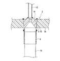
図6に、第1の脱気装置の別の一例を示す。図6に示す脱気装置1は、接続部材5と減圧チャンバー3との接合構造を除き、図1に示す脱気装置1と同様の構成を有する。
Figure 6 shows another example of a first de-KiSo location. The deaeration device 1 shown in FIG. 6 has the same configuration as the deaeration device 1 shown in FIG. 1 except for the joining structure of the
図6に示す脱気装置1では、接続部材5は、接続部材5と流通口2との間に配置されたフェルール16を介して減圧チャンバー3に接合されている。より具体的には、図6に示す脱気装置1は、図7に拡大図を示すように、以下のような接合構造を有する:接続部材5は、フェルール16とともに流通口2に挿入された状態で、減圧チャンバー3の内部側に進むにつれて径が小さくなる第1のテーパー部14をその外周面に有する。流通口2は、減圧チャンバー3の内部側に進むにつれて径が小さくなる第2のテーパー部15をその内周面に有する。フェルール16は、流通口2に挿入された状態で、減圧チャンバー3の内部側に進むにつれて径が小さくなる第3のテーパー部17をその内周面に有し、減圧チャンバー3の内部側に進むにつれて径が小さくなる第4のテーパー部18をその外周面に有する。接続部材5は、第1のテーパー部14と第3のテーパー部17とが当接し、第2のテーパー部15と第4のテーパー部18とが当接した状態で、フェルール16を介して減圧チャンバー3と接合されている。
In the deaeration device 1 shown in FIG. 6, the
このような接合構造では、減圧チャンバー3内を減圧した際に、接続部材5が減圧チャンバー3の内部に向かって押しつけられるとともに、第1のテーパー部14と第3のテーパー部17と、ならびに、第2のテーパー部15と第4のテーパー部18とをより密着させる方向へ力が働く。このとき、フェルール16がテーパー部の構造に追従するように変形するため、図1に示す脱気装置1に比べて気密性をより向上でき、減圧チャンバー3と接続部材5との接合をより確実に保持できる。
In such a joint structure, when the inside of the
フェルール16の構造、構成は、接続部材5と減圧チャンバー3とを接合できる限り特に限定されない。フェルール16の形状は、例えば、図8(a)、(b)に示すように、円錐台(円錐台A)から、当該円錐台Aと底面の中心が一致し、かつ、当該円錐台Aよりも底面の直径が小さい円錐台(円錐台B)を取り除いた形状であればよい。円錐台Aの側面が第4のテーパー部18に、円錐台Bの側面が第3のテーパー部17に相当する。図8(b)は、図8(a)に示すフェルール16の断面A−Aを示す図である。
The structure and configuration of the
第3のテーパー部17は、フェルール16の内周面の少なくとも一部に形成されていればよく、第3のテーパー部17の形状は、第1のテーパー部14と当接できる限り特に限定されない。第4のテーパー部18は、フェルール16の外周面の少なくとも一部に形成されていればよく、第4のテーパー部18の形状は、第2のテーパー部15と当接できる限り特に限定されない。
The
フェルール16を構成する材料は特に限定されないが、接続部材5および/または減圧チャンバー3との熱融着が可能であることから、熱可塑性樹脂からなるフェルール16が好ましい。
Although the material which comprises the
フェルール16を構成する熱可塑性樹脂は特に限定されず、上述した接続部材5および減圧チャンバー3を構成する樹脂と同様であればよい。
The thermoplastic resin constituting the
図6に示す脱気装置1では、接続部材5とフェルール16とが熱融着されている。図6に示す脱気装置1では、また、流通口2において、減圧チャンバー3とフェルール16とが熱融着されている。これらの場合、接続部材と減圧チャンバーとの接合をより確実に保持できる。接続部材5、減圧チャンバー3およびフェルール16が、熱可塑性樹脂以外の材料を含む場合、例えば、各々の部材の熱可塑性樹脂部同士を熱融着すればよい。
In the deaeration device 1 shown in FIG. 6, the connecting
図9に第1の脱気装置のまた別の一例を示す。図9に示す脱気装置1は、接続部材5と減圧チャンバー3との接合構造を除き、図1に示す脱気装置1と同様の構成を有する。
Showing a first another example of the de-KiSo location in FIG. The deaeration device 1 shown in FIG. 9 has the same configuration as the deaeration device 1 shown in FIG. 1 except for the joining structure of the
図9に示す脱気装置1における接続部材5は、図4に示す構成を有する。当該接続部材5と減圧チャンバー3とは、接続部材5を、減圧チャンバー3の内部から、突き当て部21が上蓋3bの内面に突き当たるように流通口2に挿入した後に、接続部材5の外周面に形成され、かつ、減圧チャンバー3の外部に突き出た雄ネジ部19に、雌ネジ部20が内周面に形成された固定部材22を螺合して締め込むことにより接合されている。このような脱気装置においても、従来の脱気装置のように接続部材と螺合する固定手段によるカシメ構造を用いることなく、脱気エレメント4と接続部材5との接続を実現でき、より信頼性に優れる脱気装置とすることができる。
The
図1および図6に示す脱気装置1では、接続部材5の流路6と連通するように、被脱気液体を脱気装置1に供給、または、被脱気液体を脱気装置1から排出するための供給排出路12が配置されている。供給排出路12は、必要に応じて配置すればよい。
In the deaeration device 1 shown in FIGS. 1 and 6, the liquid to be deaerated is supplied to the deaeration device 1 so as to communicate with the
供給排出路12の構造、構成、材質などは特に限定されず、任意に設定すればよい。例えば、図1、6に示すように、熱可塑性樹脂からなる直管状の供給排出路12であればよい。
The structure, configuration, material, and the like of the supply /
供給排出路12と接続部材5との接続方法は特に限定されないが、供給排出路12および接続部材5が熱可塑性樹脂からなる場合などには、図1、6に示すような熱融着による接続が簡便である。
The connection method between the supply /
本明細書が開示する脱気装置の製造方法は特に限定されず、基本的に、公知の方法を応用すればよい。接続部材5と、脱気エレメント4の接合片8との熱融着は、例えば、後述の実施例に記載の方法に従えばよい。
The manufacturing method of the deaeration apparatus disclosed in the present specification is not particularly limited, and basically a known method may be applied. The heat fusion between the connecting
図1に示す脱気装置1について、接続部材5と減圧チャンバー3との接合構造に着目すると、本明細書が開示する第2の脱気装置は、被脱気液体が流通する流通口を有する減圧チャンバーと、前記減圧チャンバー内に収容され、前記被脱気液体が通過する脱気エレメントと、前記流通口において前記減圧チャンバーと接合され、前記脱気エレメントを前記減圧チャンバーに固定する接続部材とを備えた脱気装置であって、前記接続部材は、前記流通口に挿入された状態で、前記減圧チャンバーの内部側に進むにつれて径が小さくなる第1のテーパー部を外周面の少なくとも一部に有し、前記流通口は、前記減圧チャンバーの内部側に進むにつれて径が小さくなる第2のテーパー部を内周面の少なくとも一部に有し、前記第1のテーパー部と前記第2のテーパー部とが当接した状態で、前記接続部材が前記減圧チャンバーと接合されている脱気装置である、ともいえる。
For deaeration apparatus 1 shown in FIG. 1, paying attention to the bonding structure between the connecting
図6に示す脱気装置1について、接続部材5と減圧チャンバー3との接合構造に着目すると、本明細書が開示する第3の脱気装置(本発明の脱気装置)は、被脱気液体が流通する流通口を有する減圧チャンバーと、前記減圧チャンバー内に収容され、前記被脱気液体が通過する脱気エレメントと、前記流通口において前記減圧チャンバーと接合され、前記脱気エレメントを前記減圧チャンバーに固定する接続部材とを備えた脱気装置であって、前記接続部材と前記流通口との間にフェルールが配置され、前記接続部材は、前記フェルールとともに前記流通口に挿入された状態で、前記減圧チャンバーの内部側に進むにつれて径が小さくなる第1のテーパー部を外周面の少なくとも一部に有し、前記流通口は、前記減圧チャンバーの内部側に進むにつれて径が小さくなる第2のテーパー部を内周面の少なくとも一部に有し、前記フェルールは、前記流通口に挿入された状態で、前記減圧チャンバーの内部側に進むにつれて径が小さくなる第3および第4のテーパー部を、それぞれ、内周面および外周面の少なくとも一部に有し、前記第1のテーパー部と前記第3のテーパー部とが当接し、かつ、前記第2のテーパー部と前記第4のテーパー部とが当接した状態で、前記接続部材が前記フェルールを介して前記減圧チャンバーと接合されている脱気装置である、ともいえる。
With regard to the deaeration device 1 shown in FIG. 6, focusing on the joint structure between the connecting
これら第2、第3の脱気装置では、従来の脱気装置のように接続部材と螺合する固定手段によるカシメ構造を用いることなく、減圧チャンバーと接続部材との接合を実現できる。このような接合構造は、上記固定手段による接合構造に比べて、接続部材が樹脂からなる場合であっても、上述した経時的なクリープが生じないため、接続部材と減圧チャンバーとの接合をより確実に保持でき、より信頼性に優れる脱気装置とすることができる。 In these second and third deaeration devices, the decompression chamber and the connection member can be joined without using a caulking structure with a fixing means screwed into the connection member as in the conventional deaeration device. Such a joining structure does not cause the above-described creep over time even when the connecting member is made of resin, compared to the joining structure by the fixing means. A degassing device that can be reliably held and is more reliable can be obtained.
以下、実施例により本発明をより具体的に説明する。本発明は、以下に示す実施例に限定されない。 Hereinafter, the present invention will be described more specifically with reference to examples. The present invention is not limited to the examples shown below.
(参照例1)
参照例1では、図1に示す構造を有する脱気装置1を作製し、被脱気液体の脱気を行った。
( Reference Example 1)
In Reference Example 1, the deaeration device 1 having the structure shown in FIG. 1 was produced, and the liquid to be deaerated was deaerated.
(脱気装置1の作製)
最初に、円棒状のポリプロピレンを切削加工して、円筒状の容器3a(肉厚5mm、内径10cm)と、円板状の上蓋3bおよび下蓋3b(肉厚5mm)とを形成した。上蓋3bおよび下蓋3bの外周面には、円板の主面に対して85°の角度を有するテーパー部を形成し、容器3aの開口部の内周面には、上記蓋体3bのテーパー部と当接する形状を有するテーパー部を形成した。次に、上蓋3bに、円形状の断面を有する3つの貫通孔を形成し、それぞれ流入口2a、流出口2bおよび接続口9とした。なお、流入口2aおよび流出口2bの内周面は、上蓋3bの主面に対して85°の角度を有する第2のテーパー部15とした。
(Production of deaeration device 1)
Initially, a cylindrical polypropylene was cut to form a
これら容器3a、上蓋3bおよび下蓋3bの作製とは別に、図3に示す形状を有する接合部材5を、PFAを用いて、切削加工により作製した。作製した接合部材5における第1のテーパー部14の角度θ1(図3参照)は85°とした。
Separately from the production of the
これら各部材の作製とは別に、内径0.95mm、膜厚0.11mm、長さ300mmのPTFEからなる気体透過性チューブ7を125本束ね、束ねた気体透過性チューブ7の両端部をPFA粉末により互いに熱融着して、チューブ束10を作製した。熱融着は、束ねた気体透過性チューブ7の両端部にPFA粉末を塗布した後に、370℃で10分間加熱(加圧を併用)することにより行った。次に、接合片8として、熱収縮性を有する円筒状のPFAパイプを2本準備し、当該パイプを上記作製したチューブ束10の双方の端部にかぶせた後に加熱して、接合片8によって、チューブ束10の端部が被覆され、かつ、支持された脱気エレメント4を作製した。
Apart from the production of these members, 125 gas permeable tubes 7 made of PTFE having an inner diameter of 0.95 mm, a film thickness of 0.11 mm, and a length of 300 mm are bundled, and both ends of the bundled gas permeable tubes 7 are made of PFA powder. To produce a
このようにして作製した脱気エレメント4の端部と、接続部材5の端部とを、以下のように熱融着して、両者を接続した:最初に、上蓋3bにおける流入口2aおよび流出口2bのそれぞれに、接続部材5の第1のテーパー部14と流入口2a(流出口2b)の第2のテーパー部15とが当接するように、接続部材5を挿入した。次に、図10に示すように、380℃に保持したプレート型の遠赤外線ヒータ24により、脱気エレメント4の接合片8の端面11と、接続部材5の端面13とを2分間加熱し、赤外線ヒータ24を除去した後、端面11と端面13とを突き当てた。次に、双方の端面を突き当てたまま全体を室温まで冷却して、脱気エレメント4と接続部材5とを、端面11と端面13とを熱融着し、接続した。なお、遠赤外線ヒータ24により端面11および端面13を加熱する際には、双方の端面以外の部分へ熱が伝わりにくいように、冷却板23を併用した。
The end portion of the
次に、容器3aの一方の開口部に、下蓋3bを、容器3aのテーパー部と下蓋3bのテーパー部とを当接させながら嵌め合わせた。次に、容器3aの他方の開口部に、脱気エレメント4が接続された接続部材5が流入口2aおよび流出口2bに挿入された上蓋3bを、脱気エレメント4が容器3a内に収容されるように、容器3aのテーパー部と上蓋3bのテーパー部とを当接させながら嵌め合わせた。
Next, the
次に、上蓋3bに形成された接続口9に減圧装置を接続し、容器3aの内部を減圧しながら、容器3aと下蓋3bと、容器3aと上蓋3bと、ならびに、上蓋3bと接続部材5とを熱融着し、接合させた。
Next, a decompression device is connected to the
最後に、PFAからなるチューブ状の供給排出路12を、接続部材5の流路6と連通するように熱融着により接続部材5に接合して、脱気装置1とした。
Finally, the tube-shaped supply /
(脱気実験)
このようにして作製した脱気装置1の減圧チャンバー3内を、接続口9に接続した減圧装置により圧力4kPaまで減圧した状態で、供給排出路12から流入口2aに水圧0.3MPaで水を10秒間供給した後に、水の供給を60秒間停止するサイクルを10万回繰り返したところ、減圧チャンバー3内には水漏れが見られず、脱気エレメント4と接続部材5との接続状態は良好であった。また、上記10万回のサイクルの後、減圧装置を停止した場合にも、減圧チャンバー3内の減圧度はほぼ変化せず、接続部材5と減圧チャンバー3との接合状態は良好であった。
(Deaeration experiment)
In the state where the inside of the
(実施例1)
実施例1では、図6に示す構造を有する脱気装置1を作製し、被脱気液体の脱気を行った。
(Example 1 )
In Example 1 , the deaeration device 1 having the structure shown in FIG. 6 was produced, and the liquid to be deaerated was deaerated.
(脱気装置1の作製)
参照例1と同様に、容器3a、上蓋3b、下蓋3b、脱気エレメント4および接続部材5を作製した。
(Production of deaeration device 1)
Similarly to the reference example 1, the
上記各部材の作製とは別に、図8に示すフェルール16を作製した。作製したフェルール16はポリプロピレンからなり、第3のテーパー部17および第4のテーパー部18の角度θ2(図8参照)は85°とした。
Separately from the production of each member, a
次に、脱気エレメント4の端部と接続部材5の端部とを、以下のように熱融着して、両者を接続した:最初に、上蓋3bにおける流入口2aおよび流出口2bのそれぞれにフェルール16を挿入し、挿入したフェルール16に接続部材5をさらに挿入して、接続部材5の第1のテーパー部14とフェルール16の第3のテーパー部17と、ならびに、フェルール16の第4のテーパー部18と流入口2a(流出口2b)の第2のテーパー部15とを、互いに当接させた。
Next, the end portion of the
次に、参照例1と同様にして、脱気エレメント4と接続部材5とを接続した。
Next, in the same manner as in Reference Example 1, the
次に、容器3aの一方の開口部に、下蓋3bを、容器3aのテーパー部と下蓋3bのテーパー部とを当接させながら嵌め合わせた。次に、容器3aの他方の開口部に、接続部材5およびフェルール16が流入口2aおよび流出口2bに挿入された上蓋3bを、脱気エレメント4が容器3a内に収容されるように、容器3aのテーパー部と上蓋3bのテーパー部とを当接させながら嵌め合わせた。
Next, the
次に、上蓋3bに形成された接続口9に減圧装置を接続し、容器2aの内部を減圧しながら、容器3aと下蓋3bと、容器3aと上蓋3bと、上蓋3bとフェルール16と、ならびに、フェルール16と接続部材5とを、熱融着し、接合させた。
Next, a decompression device is connected to the
最後に、PFAからなるチューブ状の供給排出路12を、接続部材5の流路6と連通するように熱融着により接続部材5に接合して、脱気装置1とした。
Finally, the tube-shaped supply /
(脱気実験)
このようにして作製した脱気装置1の減圧チャンバー3内を、接続口9に接続した減圧装置により圧力4kPaまで減圧した状態で、供給排出路12から流入口2aに水圧0.3MPaで水を10秒間供給した後に、水の供給を60秒間停止するサイクルを10万回繰り返したところ、減圧チャンバー3内には水漏れが見られず、脱気エレメント4と接続部材5との接続状態は良好であった。また、上記10万回のサイクルの後、減圧装置を停止した場合にも、減圧チャンバー3内の減圧度はほぼ変化せず、接続部材5とフェルール16と、ならびに、フェルール16と減圧チャンバー3との接合状態は良好であった。
(Deaeration experiment)
In the state where the inside of the
本発明によれば、従来の脱気装置のように、接続部材と螺合する固定手段によるカシメ構造を用いることなく、脱気エレメントと接続部材との接続、および/または、真空(減圧)チャンバーと接続部材との接合を実現した脱気装置を提供できる。 According to the present invention, the connection between the deaeration element and the connection member and / or the vacuum (decompression) chamber can be achieved without using a caulking structure with a fixing means screwed into the connection member as in the conventional deaeration device. It is possible to provide a deaeration device that realizes joining between the connecting member and the connecting member.
1 脱気装置
2 流通口
2a 流入口
2b 流出口
3 減圧チャンバー
3a 容器
3b 蓋体(上蓋、下蓋)
4 脱気エレメント
5、5a、5b 接続部材
6 流路
7 気体透過性チューブ
8、8a、8b 接合片
9 接続口
10 チューブ束
11 (接合片の)端面
12 供給排出路
13 (接続部材の)端面
14 第1のテーパー部
15 第2のテーパー部
16 フェルール
17 第3のテーパー部
18 第4のテーパー部
19 雄ネジ部
20 雌ネジ部
21 突き当て部
22 固定部材
23 冷却板
24 遠赤外線ヒータ
101 脱気装置
102 減圧チャンバー
103 脱気エレメント
104 接続部材
105 チューブ束
106 接合部材
107 固定用フェルール
108 固定手段
109 O−リング
110 固定手段
121 脱気装置
122 真空チャンバー
123 脱気エレメント
124 接続部材
125 チューブ束
126 外套チューブ
127 パイプ
128 雄ネジ部
129 雌ネジ部
DESCRIPTION OF SYMBOLS 1
4
Claims (8)
前記減圧チャンバー内に収容され、前記被脱気液体が通過する脱気エレメントと、
前記流通口において前記減圧チャンバーと接合され、前記脱気エレメントを前記減圧チャンバーに固定する接続部材と、を備えた脱気装置であって、
前記接続部材と前記流通口との間にフェルールが配置され、
前記接続部材は、前記フェルールとともに前記流通口に挿入された状態で、前記減圧チャンバーの内部側に進むにつれて径が小さくなる第1のテーパー部を外周面の少なくとも一部に有し、
前記流通口は、前記減圧チャンバーの内部側に進むにつれて径が小さくなる第2のテーパー部を内周面の少なくとも一部に有し、
前記フェルールは、前記流通口に挿入された状態で、前記減圧チャンバーの内部側に進むにつれて径が小さくなる第3および第4のテーパー部を、それぞれ、内周面および外周面の少なくとも一部に有し、
前記第1のテーパー部と前記第3のテーパー部とが当接し、かつ、前記第2のテーパー部と前記第4のテーパー部とが当接した状態で、前記接続部材と前記フェルールとが熱融着され、かつ、前記減圧チャンバーと前記フェルールとが熱融着されて、前記接続部材が前記フェルールを介して前記減圧チャンバーと接合されている脱気装置。 A decompression chamber having a flow port through which the liquid to be degassed flows;
A degassing element that is housed in the vacuum chamber and through which the liquid to be degassed passes;
A deaeration device comprising: a connecting member that is joined to the decompression chamber at the flow port and fixes the deaeration element to the decompression chamber;
A ferrule is disposed between the connection member and the circulation port,
The connection member has a first taper portion that decreases in diameter as it proceeds to the inside of the decompression chamber in at least a part of the outer peripheral surface in a state of being inserted into the circulation port together with the ferrule,
The flow port has a second taper portion whose diameter decreases as it goes to the inner side of the decompression chamber in at least a part of the inner peripheral surface,
When the ferrule is inserted into the circulation port, the third and fourth taper portions, the diameters of which become smaller toward the inside of the decompression chamber, are formed on at least a part of the inner peripheral surface and the outer peripheral surface, respectively. Have
When the first tapered portion and the third tapered portion are in contact with each other and the second tapered portion and the fourth tapered portion are in contact with each other, the connection member and the ferrule are heated. A degassing apparatus in which the decompression chamber and the ferrule are fused together and the connection member is joined to the decompression chamber via the ferrule.
前記流通口は、前記蓋体に形成されている請求項1に記載の脱気装置。The deaeration device according to claim 1, wherein the circulation port is formed in the lid.
Priority Applications (1)
| Application Number | Priority Date | Filing Date | Title |
|---|---|---|---|
| JP2010283412A JP5129321B2 (en) | 2006-05-01 | 2010-12-20 | Deaerator |
Applications Claiming Priority (3)
| Application Number | Priority Date | Filing Date | Title |
|---|---|---|---|
| JP2006127801 | 2006-05-01 | ||
| JP2006127801 | 2006-05-01 | ||
| JP2010283412A JP5129321B2 (en) | 2006-05-01 | 2010-12-20 | Deaerator |
Related Parent Applications (1)
| Application Number | Title | Priority Date | Filing Date |
|---|---|---|---|
| JP2007115218A Division JP4885050B2 (en) | 2006-05-01 | 2007-04-25 | Deaerator |
Publications (2)
| Publication Number | Publication Date |
|---|---|
| JP2011050964A JP2011050964A (en) | 2011-03-17 |
| JP5129321B2 true JP5129321B2 (en) | 2013-01-30 |
Family
ID=38519873
Family Applications (2)
| Application Number | Title | Priority Date | Filing Date |
|---|---|---|---|
| JP2010283411A Expired - Fee Related JP5260622B2 (en) | 2006-05-01 | 2010-12-20 | Deaerator |
| JP2010283412A Expired - Fee Related JP5129321B2 (en) | 2006-05-01 | 2010-12-20 | Deaerator |
Family Applications Before (1)
| Application Number | Title | Priority Date | Filing Date |
|---|---|---|---|
| JP2010283411A Expired - Fee Related JP5260622B2 (en) | 2006-05-01 | 2010-12-20 | Deaerator |
Country Status (5)
| Country | Link |
|---|---|
| US (1) | US7708811B2 (en) |
| EP (1) | EP1852169A3 (en) |
| JP (2) | JP5260622B2 (en) |
| KR (1) | KR20070106928A (en) |
| TW (1) | TWI388368B (en) |
Families Citing this family (7)
| Publication number | Priority date | Publication date | Assignee | Title |
|---|---|---|---|---|
| WO2008035714A1 (en) * | 2006-09-22 | 2008-03-27 | Nitto Denko Corporation | Gas removal device |
| US8192534B2 (en) * | 2007-10-13 | 2012-06-05 | Neema Hekmat | Open lumen air filtration for liquid lines |
| JP4903669B2 (en) * | 2007-10-30 | 2012-03-28 | 大日本スクリーン製造株式会社 | Substrate processing method and substrate processing apparatus |
| WO2010065028A1 (en) * | 2008-12-01 | 2010-06-10 | Halliburton Energy Services | Hollow cone degassing |
| JP6925437B2 (en) | 2017-11-13 | 2021-08-25 | 日本たばこ産業株式会社 | Circuit board for non-combustion type flavor aspirator, and non-combustion type flavor aspirator |
| GB2590130B (en) | 2019-09-23 | 2022-10-19 | Idex Health & Science Llc | Fluid degassing system with reduced pressure pulsatility |
| CN112999701B (en) * | 2019-12-20 | 2023-08-11 | 台湾积体电路制造股份有限公司 | Apparatus for removing bubbles from viscous fluids |
Family Cites Families (13)
| Publication number | Priority date | Publication date | Assignee | Title |
|---|---|---|---|---|
| IL33528A (en) * | 1968-12-27 | 1975-08-31 | Pall Corp | Sterile disposable medicament administration system |
| GB8903540D0 (en) * | 1989-02-16 | 1989-04-05 | Gore & Ass | A cross-flow filtration,or other,device having a porous tubular polytetrafluoroethylene membrane secured in an apertured wall,and the method of its manufacture |
| US5227063A (en) * | 1989-10-03 | 1993-07-13 | Zenon Environmental Inc. | Tubular membrane module |
| US5183486A (en) * | 1990-12-04 | 1993-02-02 | Spectra-Physics, Inc. | Apparatus for degassing a liquid |
| EP0598424A3 (en) * | 1992-11-16 | 1996-05-15 | Novellus Systems Inc | Device for removing dissolved gas from a liquid. |
| US5340384A (en) * | 1993-03-05 | 1994-08-23 | Systec, Inc. | Vacuum degassing |
| JP3521368B2 (en) * | 1995-08-30 | 2004-04-19 | 日東電工株式会社 | Degassing device |
| JPH09187602A (en) * | 1995-12-28 | 1997-07-22 | Japan Gore Tex Inc | Deaerator formed by using hollow fiber bundle made of fluororesin |
| JP2969075B2 (en) * | 1996-02-26 | 1999-11-02 | ジャパンゴアテックス株式会社 | Degassing device |
| US6248157B1 (en) * | 1999-08-20 | 2001-06-19 | Systec Inc. | Vacuum degassing |
| JP2001246232A (en) * | 2000-03-03 | 2001-09-11 | Japan Gore Tex Inc | Gas permeable membrane device |
| JP4341947B2 (en) * | 2002-06-14 | 2009-10-14 | 株式会社潤工社 | Separation membrane module |
| US7427312B2 (en) * | 2005-07-13 | 2008-09-23 | Rheodyne, Llc | Integrated degassing and debubbling apparatus |
-
2007
- 2007-04-26 TW TW096114716A patent/TWI388368B/en not_active IP Right Cessation
- 2007-04-30 EP EP07107251A patent/EP1852169A3/en not_active Withdrawn
- 2007-04-30 KR KR1020070041843A patent/KR20070106928A/en not_active Application Discontinuation
- 2007-05-01 US US11/799,177 patent/US7708811B2/en not_active Expired - Fee Related
-
2010
- 2010-12-20 JP JP2010283411A patent/JP5260622B2/en not_active Expired - Fee Related
- 2010-12-20 JP JP2010283412A patent/JP5129321B2/en not_active Expired - Fee Related
Also Published As
| Publication number | Publication date |
|---|---|
| US20070256561A1 (en) | 2007-11-08 |
| EP1852169A2 (en) | 2007-11-07 |
| JP2011088146A (en) | 2011-05-06 |
| TWI388368B (en) | 2013-03-11 |
| EP1852169A3 (en) | 2010-06-30 |
| KR20070106928A (en) | 2007-11-06 |
| TW200744729A (en) | 2007-12-16 |
| JP2011050964A (en) | 2011-03-17 |
| US7708811B2 (en) | 2010-05-04 |
| JP5260622B2 (en) | 2013-08-14 |
Similar Documents
| Publication | Publication Date | Title |
|---|---|---|
| JP5129321B2 (en) | Deaerator | |
| US7686867B2 (en) | Degasifier | |
| CN102971565B (en) | The disposable stream of rigidity | |
| KR20060113387A (en) | Resin pipe joint unit | |
| JP7132442B2 (en) | Multi-piece mounting device for fluid containers | |
| JP4885050B2 (en) | Deaerator | |
| JP2010264405A (en) | Degassing device | |
| JP3252919B2 (en) | Filter unit and method of manufacturing the same | |
| JP2018507100A (en) | Membrane assembly with end cap device and related methods | |
| JP3847909B2 (en) | Deaeration device and deaeration method | |
| KR101243785B1 (en) | The adapter structuer of degasification apparatus | |
| JP4105716B2 (en) | Deaeration device and deaeration method | |
| JP6408886B2 (en) | Reactor | |
| JP3616221B2 (en) | Deaerator | |
| JP3585077B2 (en) | Degassing device | |
| JP2005305442A (en) | Deaerator and deaeration method | |
| JPH08150302A (en) | Deaerator | |
| EP3446861A1 (en) | Method for sealing medical devices | |
| JPH11267406A (en) | Deaerating device | |
| JPH0957008A (en) | Deaerator | |
| JPH105503A (en) | Deaeration device | |
| JPH0478396A (en) | Joint tube and manufacture thereof |
Legal Events
| Date | Code | Title | Description |
|---|---|---|---|
| A977 | Report on retrieval |
Free format text: JAPANESE INTERMEDIATE CODE: A971007 Effective date: 20120809 |
|
| A131 | Notification of reasons for refusal |
Free format text: JAPANESE INTERMEDIATE CODE: A131 Effective date: 20120904 |
|
| A521 | Written amendment |
Free format text: JAPANESE INTERMEDIATE CODE: A523 Effective date: 20121009 |
|
| TRDD | Decision of grant or rejection written | ||
| A01 | Written decision to grant a patent or to grant a registration (utility model) |
Free format text: JAPANESE INTERMEDIATE CODE: A01 Effective date: 20121030 |
|
| A01 | Written decision to grant a patent or to grant a registration (utility model) |
Free format text: JAPANESE INTERMEDIATE CODE: A01 |
|
| A61 | First payment of annual fees (during grant procedure) |
Free format text: JAPANESE INTERMEDIATE CODE: A61 Effective date: 20121101 |
|
| R150 | Certificate of patent or registration of utility model |
Free format text: JAPANESE INTERMEDIATE CODE: R150 |
|
| FPAY | Renewal fee payment (event date is renewal date of database) |
Free format text: PAYMENT UNTIL: 20151109 Year of fee payment: 3 |
|
| LAPS | Cancellation because of no payment of annual fees |