JP5122863B2 - Method for manufacturing long member having flexible cross section using roll and cold roll forming apparatus for flexible cross section material - Google Patents
Method for manufacturing long member having flexible cross section using roll and cold roll forming apparatus for flexible cross section material Download PDFInfo
- Publication number
- JP5122863B2 JP5122863B2 JP2007121755A JP2007121755A JP5122863B2 JP 5122863 B2 JP5122863 B2 JP 5122863B2 JP 2007121755 A JP2007121755 A JP 2007121755A JP 2007121755 A JP2007121755 A JP 2007121755A JP 5122863 B2 JP5122863 B2 JP 5122863B2
- Authority
- JP
- Japan
- Prior art keywords
- roll
- roll forming
- supply
- bending
- cutting
- Prior art date
- Legal status (The legal status is an assumption and is not a legal conclusion. Google has not performed a legal analysis and makes no representation as to the accuracy of the status listed.)
- Active
Links
Images


Landscapes
- Bending Of Plates, Rods, And Pipes (AREA)
Description
本発明は、長尺部材を折り曲げてフレキシブル断面を有する部材を製造する方法及びこれを実施する装置に関し、特に詳細には、コイル材を自由曲線に沿って切断してブランク材を形成するとともに、この形成されたブランク材板縁から所望する折り曲げ予定ラインに沿って、板縁に沿って曲げ成形して、フレキシブル断面を有する長尺部材を連続的に製造する方法及びこれを実施する冷間ロール装置に関する。 The present invention relates to a method of manufacturing a member having a flexible cross section by bending a long member and an apparatus for carrying out the method, and more particularly, cutting a coil material along a free curve to form a blank material, A method of continuously producing a long member having a flexible cross-section by bending along a plate edge along a desired folding line from the formed blank material plate edge, and a cold roll for carrying out the method Relates to the device.
断面の幅、断面の形状が連続的に変化する製品は、従来、プレス装置、ベンダー、プレスブレーキなどによって成形されていた。しかし、これらの装置による方法は、その装置の加工範囲以上の長尺の製品を製造するのに適していない。また、10m から20m のような長い製品を、これらの方法で製造するための装置は非常に大型になるほか、高コストとなる。また、断面の幅が連続的に変化する長尺部材を製造する装置として、本件出願人が出願した特許文献1に示すような製造装置が知られている。
プレス装置やプレスブレーキによって長尺製品を製造する方法は、装置が大型であり、かつ、高コストである。特に、プレス装置による製造技術は、製品の形状が変わる度に、専用の金型を準備しなければならず、金型費用は莫大となる。また、前記特許文献1に示す製造装置では、まだ所望の断面形状を有する長尺部材を製造することができなかった。 In the method of manufacturing a long product using a press device or a press brake, the device is large and expensive. In particular, in the manufacturing technology using a press apparatus, a dedicated die must be prepared every time the shape of the product changes, and the die cost is enormous. Moreover, in the manufacturing apparatus shown in the said patent document 1, the elongate member which has a desired cross-sectional shape was not able to be manufactured yet.
本発明は、上記問題を解決し、断面形状がいろいろに変化しても、専用の金型を製作することなく、連続的に且つ所望の形状を有する長尺部材を製造する方法及びこの方法を実施する装置を提供する。 The present invention solves the above-described problem, and provides a method for manufacturing a long member having a desired shape continuously and without producing a dedicated mold even when the cross-sectional shape changes variously. An apparatus for performing is provided.
本発明は、前記目的を達成するために提唱されたものであり、請求項1記載の発明は、長尺材料をその長手方向に連続的に供給する供給工程と;
長尺材料の前記長手方向に直交する方向におけるブランク材の幅及び折り曲げ予定位置を制御装置に入力されて設定する設定工程と、
連続的に供給された長尺部材を、ブランク材の幅が制御装置より入力された切断幅に基づき自動走行型レーザ切断装置のACサーボモータを制御し、アクチュエータを介して移動機構を動かしレーザ発生部のレーザ照射位置を動かし、供給されたレーザ発生部の長尺部材を前記設定工程で設定された幅と同じになるように、長尺部材を、その供給方向に連続的に切断し、所望の輪郭形状を有するブランク材を作成する第1の切断工程と;
前記切断工程の切断位置より、前記ブランク材の供給方向において、所定の距離だけ下流側に設けられ、ロール位置を供給方向に直交する方向に移動可能であるとともに、ロール軸の前記供給方向に対する傾斜角度を連続的に変更可能なタンデムフレキシブル冷間ロール成形装置を用い、前記ロール成形装置の前記供給方向に直交する方向における移動及び傾斜角度を、前記ブランク材の移動速度に基づいて、ロール成形装置のロール成形位置において、前記折り曲げ予定位置の時間的移動方向に対して、前記ロール軸の前記供給方向に対する直交する方向に対する角度を直角に保持するようにして、ロール成形を行い、前記折り曲げ予定位置において、前記ブランク材の端部を連続的に折り曲げる曲げ成形工程と:
を備えたPLC制御による成形工程を特徴とするフレキシブル断面を有する長尺部材の製造方法を提供する。
The present invention has been proposed in order to achieve the above object, and the invention according to claim 1 includes a supplying step of continuously supplying a long material in a longitudinal direction thereof;
A setting step for inputting and setting the width and the expected bending position of the blank material in the direction perpendicular to the longitudinal direction of the long material, to the control device ;
Continuously supplied long members control the AC servo motor of the automatic traveling laser cutting device based on the cutting width of blank material input from the control device, and move the moving mechanism via the actuator to generate laser moving the laser irradiation position of the parts, so that the elongated member of the laser generator supplied the same set width in the setting step, the elongated member, and continuously cut in the supply direction, the desired A first cutting step of creating a blank material having the following contour shape;
Provided downstream from the cutting position of the cutting step by a predetermined distance in the blank material supply direction, the roll position can be moved in a direction perpendicular to the supply direction, and the roll shaft is inclined with respect to the supply direction. Using a tandem flexible cold roll forming apparatus capable of continuously changing the angle, the roll forming apparatus is configured to determine the movement and the inclination angle in the direction orthogonal to the supply direction of the roll forming apparatus based on the moving speed of the blank material. In the roll forming position, roll forming is performed such that the angle of the roll shaft with respect to the direction orthogonal to the supply direction is held at a right angle with respect to the temporal movement direction of the planned bending position. In the bending process of continuously bending the end of the blank material:
The manufacturing method of the elongate member which has a flexible cross section characterized by the shaping | molding process by PLC control provided with is provided.
上記製造方法では、長尺部材の折り曲げ予定位置で、折り曲げを実施するロール成形装置のロール軸を、折り曲げ予定位置の時間的移動方向に対して、常に直角に保持した状態で、ロール成形するため、所望の形状の折り曲げ予定ラインに沿って、所望に断面形状を有する長尺部材を成形することが可能となる。 In the manufacturing method described above, roll forming is performed in a state in which the roll shaft of the roll forming apparatus that performs the bending is always held at a right angle with respect to the temporal movement direction of the planned bending position at the planned bending position of the long member. It becomes possible to form a long member having a desired cross-sectional shape along a planned bending line of a desired shape.
また、請求項2記載の発明は、請求項1記載の長尺部材の製造方法において、更に、前記曲げ成形工程完了後、曲げ成形された長尺部材を、供給方向に沿って、所望の長さに切断する第2の切断工程を備えたPLC制御による成形工程を特徴とするフレキシブル断面を有する長尺部材の製造方法を提供する。 According to a second aspect of the present invention, in the method of manufacturing a long member according to the first aspect, after the bending process is completed, the long member that has been bent is formed into a desired length along the supply direction. The manufacturing method of the elongate member which has a flexible cross section characterized by the shaping | molding process by PLC control provided with the 2nd cutting process cut | disconnected to length is provided.
このように、第2の切断工程を設けることにより、所定の長さを有する長尺部材を、連続して製造することができ、製造効率を向上させることができる。 Thus, by providing a 2nd cutting process, the elongate member which has predetermined | prescribed length can be manufactured continuously, and manufacturing efficiency can be improved.
また、請求項3記載の発明は、請求項1又は2記載のフレキシブル断面を有する長尺部材の製造方法において、前記曲げ成形工程を、複数段設けてあるPLC制御による成形工程を特徴とするフレキシブル断面を有する長尺部材の製造方法を提供する。
The invention described in
このように構成することにより、長尺部材の折り曲げを段階的に行うことができるため、所望の断面形状を有する長尺部材を製造することができる。 By comprising in this way, since a long member can be bent in steps, the long member which has a desired cross-sectional shape can be manufactured.
また、請求項4記載の発明は、請求項1、2又は3記載のフレキシブル断面を有する長尺部材の製造方法において、前記曲げ成形工程での前記ロール装置は、各段の上下成形ロール曲げ角度も周速度の材料送り方向速度ベクトルは前記長尺部材の供給速度と同じになるように制御されていることを特徴とするPLC制御による成形工程を採用したフレキシブル断面を有する長尺部材の製造方法を提供する。 According to a fourth aspect of the present invention, in the method for producing a long member having a flexible cross section according to the first, second, or third aspect, the roll device in the bending step includes an upper and lower forming roll bending angle at each stage. material feeding direction velocity vector also peripheral speed manufacture of elongated members having a flexible section that employs a molding process by PLC control, characterized in that it is controlled to be the same as the feed rate of the elongated member Provide a method.
このようにロールの周速度を制御することにより、ロール成形装置でのブランク材の送りがスムーズになり、ブランク材のフランジ部が座屈するのを防ぐことができ、より所望の形状を有する長尺部材を製造することができる。 By controlling the peripheral speed of the roll in this way, the blank material can be smoothly fed in the roll forming apparatus, the flange portion of the blank material can be prevented from buckling, and the long shape having a more desired shape can be obtained. A member can be manufactured.
また、請求項5記載の発明は、長尺部材をその長手方向に連続的に供給する供給装置と;
長尺材料の前記長手方向に直交する方向におけるブランク材の幅及び折り曲げ予定位置を制御装置に入力されて設定する設定装置と、
前記供給装置の後段に設けられ、連続的に供給された長尺部材を、ブランク材の幅が前記設定装置で設定された幅と同じになるように、長尺部材を、長尺部材の供給方向に連続的に切断し、所望の輪郭形状を有するブランク材を作成する切断装置と;
前記切断工程の切断位置より、前記ブランク材の供給方向において、所定の距離だけ下流側に設けられ、ロール位置を供給方向に直交する方向に移動可能であるとともに、ロール軸の前記供給方向に対する傾斜角度を連続的に変更可能なロール成形装置と、
長尺材料の前記長手方向に直交する方向におけるブランク材の幅及び折り曲げ予定位置に関するデータを受け取り、前記供給装置、前記設定装置、前記切断装置及び前記ロール成形装置を制御し、前記ロール成形装置の前記供給方向に直交する方向における移動及び傾斜角度を、前記ブランク材の移動速度に基づいて、ロール成形装置のロール成形位置において、前記折り曲げ予定位置の時間的移動方向に対して、前記ロール軸の前記供給方向に対する直交する方向に対する角度を直角に保持するようにして、ロール成形を行い、前記折り曲げ予定位置において、前記ブランク材の端部を連続的に折り曲げることを実施させる制御装置と、
を備えたPLC制御による成形装置を特徴とするフレキシブル断面を有する長尺部材の冷間ロール成形装置を提供する。
The invention according to claim 5 is a supply device for continuously supplying a long member in its longitudinal direction;
A setting device for setting the width of the blank material and the planned bending position in the direction orthogonal to the longitudinal direction of the long material by being input to the control device;
Supplying the long member to the long member provided in the subsequent stage of the supply device so that the width of the blank is the same as the width set by the setting device A cutting device that continuously cuts in a direction to create a blank having a desired contour shape;
Provided downstream from the cutting position of the cutting step by a predetermined distance in the blank material supply direction, the roll position can be moved in a direction perpendicular to the supply direction, and the roll shaft is inclined with respect to the supply direction. A roll forming device capable of continuously changing the angle;
Data on the width of the blank material and the expected bending position in the direction perpendicular to the longitudinal direction of the long material is received, the supply device, the setting device, the cutting device, and the roll forming device are controlled, and the roll forming device Based on the moving speed of the blank material, the movement and the inclination angle in the direction orthogonal to the supply direction are determined in the roll forming position of the roll forming apparatus with respect to the temporal movement direction of the planned bending position of the roll shaft. so as to retain its angle to the direction perpendicular to said feeding direction at a right angle, performs a roll forming, in said folded position scheduled, and a control device for implementing the Rukoto folding the ends of the blank continuously,
A long roll cold roll forming apparatus having a flexible cross section characterized by a PLC control forming apparatus provided with
上記の製造装置では、長尺部材の折り曲げ予定位置で、折り曲げを実施するロール成形装置のロール軸を、折り曲げ予定位置の時間的移動方向に対して、常に直角に保持した状態で、ロール成形するため、所望の形状の折り曲げ予定ラインに沿って、所望に断面形状を有する長尺部材を成形することが可能となる。 In the manufacturing apparatus described above, roll forming is performed in a state in which the roll shaft of the roll forming apparatus that performs the bending is always held at a right angle with respect to the temporal movement direction of the planned bending position at the planned bending position of the long member. For this reason, it is possible to form a long member having a desired cross-sectional shape along a planned bending line having a desired shape.
本発明の上記の目的および他の目的、特徴、並びに利点は、添付図面を参照して進められる本発明の好適な実施の形態の以下の詳細な記述から、より容易に明らかになる。 The above and other objects, features, and advantages of the present invention will become more readily apparent from the following detailed description of preferred embodiments of the present invention, which proceeds with reference to the accompanying drawings.
以上説明したように、本発明によれば、フレキシブル断面を有する長尺部材を効率的に、且つ連続的に製造することができる製造方法及びこれを実施する冷間ロール製造装置が提供される。
また、本発明では、PLC(Programmable logic controller)制御による成形工程を特徴とするフレキシブル断面を有する長尺部材の製造方法または成形装置であるため以下のような特有の効果を有する。
(i)すなわち、本発明によるフレキシブル断面材の製造装置は、プレス装置では製造が不可能である長尺の製品を製作することができる。
(ii)また、断面の形状が変化した場合でも、プレス装置の場合のように、その都度、専用の金型を製作する必要はない。
(iii)この結果、金型製作費用が不要になるほか、金型のセットに要する作業時間も不要となる。これ等の事項は、設定を組み替えるのみで済ませることができるからである。
As described above, according to the present invention, a production method capable of efficiently and continuously producing a long member having a flexible cross section and a cold roll production apparatus for carrying out the production method are provided.
In addition, the present invention has the following specific effects because it is a method or apparatus for producing a long member having a flexible cross section characterized by a molding process by PLC (Programmable Logic Controller) control.
(I) That is, the flexible cross-section material manufacturing apparatus according to the present invention can manufacture a long product that cannot be manufactured by a press apparatus.
(Ii) Even when the shape of the cross section changes, it is not necessary to manufacture a dedicated die each time as in the case of a press device.
(Iii) As a result, the mold manufacturing cost is not required, and the work time required for setting the mold is not required. This is because these matters can be completed only by rearranging the settings.
以下、添付図面を参照するとともに、本発明の一実施例であるフレキシブル断面を有する長尺部材の冷間ロール成形装置の実施例を説明するとともに、フレキシブル断面を有する長尺部材の製造方法について詳細に説明する。 Hereinafter, while referring to an accompanying drawing and explaining an example of a cold roll forming device of a long member which has a flexible section which is one example of the present invention, it is detailed about a manufacturing method of a long member which has a flexible section Explained.
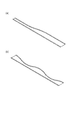
図1は、本発明の一実施例であるフレキシブル断面を有する長尺部材の冷間ロール成形装置の概観を示す図である。また、図2は、上記ロール成形装置で製造されるフレキシブル断面を有する長尺部材を示す。図2(a)は、傾斜直線で切断したブランク材(折り曲げ部を有していない状態の長尺部材)の板縁を板縁に沿って曲げ起こしたときの長尺部材を示し、図2(b)は、曲線切断されたブランク材の板縁を曲線板縁に沿って曲げ起こした長尺部材を示す。 FIG. 1 is a diagram showing an overview of a cold roll forming apparatus for a long member having a flexible cross section according to an embodiment of the present invention. Moreover, FIG. 2 shows the elongate member which has a flexible cross section manufactured with the said roll forming apparatus. FIG. 2 (a) shows the long member when the plate edge of the blank material (long member without a bent portion) cut along the inclined straight line is bent along the plate edge. (B) shows the elongate member which bent up the board edge of the blank material by which curve cutting was carried out along the curve board edge.
図1に示すように、本発明の一実施例である冷間ロール装置10は、各種フレキシブル断面材を製造する概略ラインを実現するものであり、長尺部材の材料である成形用コイル材1を供給する材料供給部2と、その後段に設けられ、材料供給部2から供給された長尺部材の材料を連続的に受け入れる入り口ガイド部3と、供給された長尺部材の材料を所定の供給速度で後段に供給するとともに、長尺部材の一側面を所望の幅だけ曲げ立ち上げるタンデム冷間ロール成形装置部4と、更に、その後段に設けられ、供給された長尺部材を供給方向に沿って連続的に切断する自動走行型レーザ切断装置5と、自動走行型レーザ切断装置5の後段に設けられ、自動走行型レーザ切断装置で形成されたブランク材を所望の連続的に変化する断面形状を有する長尺部材にロール成形する冷間ロール成形装置6と、更に、冷間ロール成形装置6の後段に設けられ、冷間ロール成形装置6で所望の連続した断面形状を有する長尺部材を、所定の長さに切断する自動走行型切断装置7と、これらの成形装置を一体的に制御する制御装置8とにより構成されている。また、本実施例では、冷間ロール成形装置6は、3段の冷間ロール成形装置6a、6b、6cで構成され、供給されたブランク材を、段階的にロール成形し、所望の連続的な断面形状を有する長尺部材を成形している。
As shown in FIG. 1, the
この冷間ロール装置10には、更に各種のセンサーが設けられ、連続して流れている長尺部材の材料、ブランク材、成形された長尺部材の位置、形状、供給速度等を計測している。また、制御装置8は、自動走行型レーザ切断装置5で連続的に切断することにより形成するブランク材の連続的に変化する幅に関する位置制御指令データを、ブランク材の折り曲げ予定ラインの位置制御指令データとして用いるための入力装置を有している。そして、ロ−タエンコーダで計測されたデータは、制御装置8に入力され、制御装置8は、これらの入力されたデータに基づいて、自動走行型レーザ切断装置5および冷間ロール成形装置6、更に自動走行型切断装置7とを制御している。
This
図3は、図1に示す入り口ガイド部3と冷間ロール成形装置4の構成を示す。入り口ガイド部3は、図に示すように、コイル材1が板幅方向に移動するのを止めるガイド部3aを備え、更にコイル材1を送る機能(図示せず)を備えている。また、この冷間ロール成形装置4は、図に示すように3段の冷間ロールより構成され、入り口ガイド部3から供給されてきたコイル材の側面を折り曲げ、一定の高さを有するL字形状の断面を成形する。この冷間ロール成形装置4は、通常使用されているものであり、当業者にとって明瞭なものであるため詳細な説明は省略する。
FIG. 3 shows a configuration of the
次に図4は、図1の自動走行型レーザ切断装置5の詳細構成を示す。これは、自動走行型レーザ切断装置5は、切断用のレーザを発生するレーザ発生部5aと、制御装置8からの制御指令で長尺部材の板幅方向にレーザ発生部5aを移動させる移動機構5bとを備え、レーザ発生部5aは、移動機構5b上に搭載されている。この移動機構5bは、制御指令で動作するACサーボモータ5c、このACサーボモータ5cの回転に基づいてレーザ発生部5aを移動させるアクチュエータ5dと、アクチュエータ5dを搭載しているプレート5eで構成されている。コイル材を直線、あるいは曲線に切断する方法は、一定速度で供給される長尺部材に対して、レーザ発生部5aを供給されてくる長尺部材の板幅方向の移動位置を変えることによって行っている。そして、レーザ発生部5aから発生するレーザにより、制御装置8からの制御指令に基づいて、長手方向にそって、連続的に変化する任意の板幅を持ったブランク材を形成することができる。
Next, FIG. 4 shows a detailed configuration of the automatic traveling laser cutting device 5 of FIG. The automatic traveling laser cutting device 5 includes a
図5は、図1に示すタンデムフレキシブル冷間ロール成形装置6の単段の構成を示す。そして、図6は、このタンデムフレキシブル冷間装置6a等の断面構造を示す。タンデムフレキシブル冷間ロール成形装置6aは、ロール部6dと、このロール部を自動走行型レーザ切断装置5の備えられている移動機構5dと同様な構造を有する移動機構6eと、さらにロール部の曲げ角部(ロールの中心)を中心として、ロール部のロール軸Qを、ブランク材の供給方向に対して所望の角度となるようにロール部6dを回転する機構6fを加えたものである。これは、移動機構6eの移動プレート6h上に、図示のような片持ち支持の冷間ロール成形装置6jを回転可能な円盤6fに固定してあり、この円盤6fをタイミングベルト6kによって、ACサーボモータ6mの動力が伝達する機構になっている。なお、円盤6fの回転中心Pの真上延長上にロールの曲げ角部がくるように設計されている。また、円盤6fに固定されるロール保持部6jには速度可変型のロール駆動用サーボモータ6nが設けられ、このロール駆動用サーボモータ6nにより、ロール部6dは、制御装置8からの制御指令により、任意の速度で回転する。
FIG. 5 shows a single-stage configuration of the tandem flexible cold roll forming apparatus 6 shown in FIG. FIG. 6 shows a sectional structure of the tandem flexible
そして、この単段のタンデムフレキシブル冷間ロール成形装置6aが、3段、設けられている。
And this single stage tandem flexible cold
このタンデムフレキシブル冷間ロール成形装置6の後段に設けてあり、冷間ロール成形され、所望の断面形状を有する長尺部材を、任意の長さに切断するレーザ切断装置7の構造については、通常のレーザ切断装置と同様な構造を有しているため、詳細な説明は省略する。 Regarding the structure of the laser cutting device 7 which is provided in the subsequent stage of the tandem flexible cold roll forming device 6 and which is cold roll formed and cuts a long member having a desired cross-sectional shape into an arbitrary length, Since it has the same structure as the laser cutting apparatus, detailed description is omitted.
次に、上記冷間ロール装置10で、フレキシブルな断面を有する長尺材の製造方法について説明する。
Next, the manufacturing method of the elongate material which has a flexible cross section with the said
本実施例の製造方法では、コイル材を連続して冷間ロール装置10の入り口部3に供給する材料供給工程と、制御装置8に、長尺材料の長手方向に直交する方向で、自動走行型レーザ切断装置5で切断させる長手方向の幅(切断幅)及び曲げしろ(立ち上げ幅)すなわち、折り曲げ予定位置を設定する設定工程と、連続的に供給された長尺部材を、ブランク材の幅が前記設定工程で設定された幅と同じになるように、長尺部材を、長尺部材の供給方向に連続的に切断し、所望の輪郭形状を有するブランク材を作成する切断工程と、この切断され、形成されたブランク材を、設定工程で設定された折り曲げ予定位置に沿って、折り曲げ、立ち上げる曲げ成形工程と、この曲げ成型された長尺材を、制御装置8の制御により所定に長さに切断する切断工程が実施される。
In the manufacturing method of the present embodiment, the material material supplying step for continuously supplying the coil material to the
ここで、材料供給工程については、コイル材は、その長手方向に一定の速度で、供給される。 Here, in the material supply process, the coil material is supplied at a constant speed in the longitudinal direction.
設定工程では、切断幅及び折り曲げ予定位置が、制御装置8に入力され、設定される。
In the setting step, the cutting width and the bending position are input to the
切断工程では、制御装置8より入力された切断幅に基づいて、自動走行型レーザ切断装置5のACサーボモータ5cを制御し、アクチュエータ5dを介して、移動機構5bを動かし、レーザ発生部5aのレーザ照射位置の動かし、材料供給工程から供給されたレーザ発生部5aの長尺材を設定された切断幅(長手方向に沿って直線または曲線状)に沿って切断し、ブランク材を成形する。
In the cutting step, the
次に曲げ成形工程では、設定工程で入力された折り曲げ予定位置、切断幅に基づいて計算された、ロールの曲げ位置、ロール軸の角度、ロールの回転速度
が計算され、この計算された値に基づいて、タンデムフレキシブル冷間ロール成形装置6のACサーボモータ6g及び6mを動かし、ロールの幅方向への送り量、ロール軸方向が、曲げ予定位置における時間的変化方向に対して直交するようにロール軸を制御し、設定された予定位置で、供給されてきたブランク材を折り曲げ、所望のフレキシブルな断面形状を有する長尺部材を成形する。また、制御装置8の制御信号により、ACサーボモータ6nを駆動され、ロールの回転速度は、制御装置8で計算されたロールの回転速度を保持されている。
なお、切断工程、曲げ成形工程での切断装置、フレキシブル冷間ロール成形装置の制御において、切断装置とフレキシブル冷間ロール成形装置との間隔、また多段のフレキシブル冷間ロール成形装置が設けられている場合には、それぞれに設けられているACサーボモータ等の制御を、それらの配置間隔に基づいて、遅延させて動かすことより、制御装置8の計算・演算量を減らすことも可能である。
Next, in the bending process, the bending position of the roll, the angle of the roll axis, and the rotation speed of the roll calculated based on the planned bending position and cutting width input in the setting process are calculated. Based on this, the
In addition, in control of the cutting device in the cutting step, the bending forming step, and the flexible cold roll forming device, an interval between the cutting device and the flexible cold roll forming device, and a multi-stage flexible cold roll forming device are provided. In some cases, it is also possible to reduce the amount of calculation / calculation of the
次にロール軸と折り曲げ予定位置の関係について、図7を用いて説明する。
図7において、ブランク材は、Y軸方向に送られており、設定工程で設定された、自動走行型レーザ切断装置5により切断された切断ライン7aで外形が規定されている。ここで、点線で示す、折り曲げ位置(ライン)7bは、切断ライン7aから、一定の距離だけ内側に入った位置であり、これは、フランジを目的の幅にするために、その都度、制御装置8において、「曲げしろ」として目的の幅の値を入力する。点線7bが板縁と同じ曲線状の形状になるためには、ロータエンコーダで計測されたブランク材の送り量dyと板幅の変化量dx(自動走行型レーザ切断装置5が移動する変化量)からtanθ=dx/dy(時間的変化)を制御装置8で計算して、この角度θでロール軸Qが向きを変えている。このようにロール軸の角度を設定することより、ロールによるスムーズな折曲げが実現でき、また、ブランク材の折り曲げ部での歪みを抑えることができる。
Next, the relationship between the roll axis and the planned bending position will be described with reference to FIG.
In FIG. 7, the blank is sent in the Y-axis direction, and the outer shape is defined by the
次にロールの回転速度と曲げ予定位置との関係について図8を用いて説明する。図7で説明したようにロール軸は、折り曲げ予定ライン7bの時間的変化(傾斜)に対して直交させて、ロール成形を行うが、その際、折り曲げ予定ライン7bとロールとの接触点での送り速度Vr(ロール曲げ角部周速度)が、上記傾斜とブランク材の送り方向(Y軸方向)と角度θをなすとき、Vr=V/cosθ(Vは、ブランク材送り速度)となるようなVrの値でロール成形を行う。もし、ロールの周速度Vrをブランク材の送り速度Vと同じであると、図示のように傾斜している部分では、ロール曲げ角部周速度ベクトルの余弦成分(Vr×cosθ)は材料送り速度Vより遅くなるため、ブランク材の送りにブレーキをかけることになる。これは、ブランク材に無用なひずみをが生じ、縁波、いわゆる座屈を生じる。
Next, the relationship between the rotation speed of the roll and the planned bending position will be described with reference to FIG. As described with reference to FIG. 7, the roll axis is orthogonal to the temporal change (inclination) of the planned
上記製造装置で板幅150mm、長さ4000mm、板厚0.5mmの冷間圧延鋼板(SPCC 材)を曲線に沿って、曲げしろ(フランジ幅)10mm、曲げ角度60度に3段のロール(曲げ角度20、40、60度)で曲げ起こした。また、鋼板のもう一方の側は、コイル材の挿入側の冷間ロール成形装置でフランジ幅8mm、曲げ角度90 度に3 段のロール(曲げ角度30、60、90度)で曲げ起こした。 With the above manufacturing equipment, cold rolled steel plate (SPCC material) with a plate width of 150 mm, length of 4000 mm, and plate thickness of 0.5 mm along the curve, bend (flange width) 10 mm, 3 rolls (bending) at a bending angle of 60 degrees Bending occurred at angles of 20, 40, and 60 degrees. Further, the other side of the steel plate was bent and raised by a three-stage roll (bending angle 30, 60, 90 degrees) at a flange width of 8 mm and a bending angle of 90 degrees by a cold roll forming apparatus on the coil material insertion side.
次に、曲線の板縁から一定の位置を曲げ起こすと、フランジの凸側は圧縮、凹側は引張りの応力が働く。いわゆる、プレス成形の縮みフランジ、伸びフランジの現象が生じる。この現象で生じたひずみは、断面の平らなウエブ部分の平胆度を悪くすることが懸念された。しかし、フランジ幅Fと板厚tの比率(F/t)が小さいため(F/t(10/0.5)=20)か、このような懸念事項は認められなかった。 Next, when a certain position is bent from the curved plate edge, compression is applied to the convex side of the flange and tensile stress is applied to the concave side. A so-called shrink-formed flange or stretched flange phenomenon occurs. There is a concern that the strain caused by this phenomenon may deteriorate the flatness of the web portion having a flat cross section. However, because the ratio (F / t) between the flange width F and the plate thickness t is small (F / t (10 / 0.5) = 20), such a concern was not recognized.
本発明のロールを用いてフレキシブル断面を有する長尺部材の製造方法およびフレキシブル断面材の冷間ロール成形装置は、上記実施例に限定されず、種々の変形例、応用例が考えられる。 The manufacturing method of the elongate member which has a flexible cross section using the roll of this invention, and the cold roll shaping | molding apparatus of a flexible cross-section material are not limited to the said Example, Various modifications and application examples can be considered.
例えば、上記実施例では、曲げしろ(フランジ幅)を設定しているが、タンデムフレキシブル冷間ロール成形装置6a、6b、6c等をブランク材の切断端部から、ブランク材の幅方向に可変に移動させることより、連続して変化する立ち上げ高さ有するフレキシブルな断面を有する長尺材を製造できる。
For example, in the above embodiment, the bending margin (flange width) is set, but the tandem flexible cold
上述のように、本発明のフレキシブル断面材の製造装置は、以上述べたようなPLC制御による製造装置であるために、以下のような効果を有する。 As described above, the flexible cross-section material manufacturing apparatus of the present invention is a manufacturing apparatus based on PLC control as described above, and thus has the following effects.
すなわち、本発明によるフレキシブル断面材の製造装置は、プレス装置では製造が不可能である長尺の製品を製作できる。 That is, the flexible cross-section material manufacturing apparatus according to the present invention can manufacture a long product that cannot be manufactured by a press apparatus.
また、断面の形状が変化した場合でも、プレス装置の場合のように、その都度、専用の金型を製作する必要はない。 Even when the shape of the cross section changes, it is not necessary to manufacture a dedicated die each time as in the case of a press device.
この結果、金型製作費用が不用になるほか、金型のセットに要する作業時間も不要となる。これらの事項は、設定を組み替えるのみで済ませることができる。 As a result, the mold manufacturing cost is not required, and the work time required for setting the mold is not required. These matters can be done only by rearranging the settings.
1…成形用コイル材、2…材料供給部、3…入り口ガイド部、4…冷間ロール成形装置、5…自動走行型レーザ切断装置、6…タンデムフレキシブル冷間ロール成形装置、7…自動走行型切断装置、8…制御装置、5c、6g、6m…ACサーボモータ、6n…ロール駆動用サーボモータ、6d…ロール部、10…冷間ロール装置。 DESCRIPTION OF SYMBOLS 1 ... Molding coil material, 2 ... Material supply part, 3 ... Entrance guide part, 4 ... Cold roll forming apparatus, 5 ... Automatic traveling type laser cutting apparatus, 6 ... Tandem flexible cold roll forming apparatus, 7 ... Automatic traveling Die cutting device, 8 ... control device, 5c, 6g, 6m ... AC servo motor, 6n ... roll driving servo motor, 6d ... roll unit, 10 ... cold roll device.
Claims (5)
長尺材料の前記長手方向に直交する方向におけるブランク材の幅及び折り曲げ予定位置を制御装置に入力されて設定する設定工程と、
連続的に供給された長尺部材を、ブランク材の幅が制御装置より入力された切断幅に基づき自動走行型レーザ切断装置のACサーボモータを制御し、アクチュエータを介して移動機構を動かしレーザ発生部のレーザ照射位置を動かし、供給されたレーザ発生部の長尺部材を前記設定工程で設定された幅と同じになるように、長尺部材を、その供給方向に連続的に切断し、所望の輪郭形状を有するブランク材を作成する第1の切断工程と;
前記切断工程の切断位置より、前記ブランク材の供給方向において、所定の距離だけ下流側に設けられ、ロール位置を供給方向に直交する方向に移動可能であるとともに、ロール軸の前記供給方向に対する傾斜角度を連続的に変更可能なタンデムフレキシブル冷間ロール成形装置を用い、前記ロール成形装置の前記供給方向に直交する方向における移動及び傾斜角度を、前記ブランク材の移動速度に基づいて、ロール成形装置のロール成形位置において、前記折り曲げ予定位置の時間的移動方向に対して、前記ロール軸の前記供給方向に対する直交する方向に対する角度を直角に保持するようにして、ロール成形を行い、前記折り曲げ予定位置において、前記ブランク材の端部を連続的に折り曲げる曲げ成形工程と;
を備えたPLC制御による成形工程を特徴とするフレキシブル断面を有する長尺部材の製造方法。 A supply step of continuously supplying a long material in its longitudinal direction;
A setting step for inputting and setting the width and the expected bending position of the blank material in the direction perpendicular to the longitudinal direction of the long material, to the control device ;
Continuously supplied long members control the AC servo motor of the automatic traveling laser cutting device based on the cutting width of blank material input from the control device, and move the moving mechanism via the actuator to generate laser moving the laser irradiation position of the parts, so that the elongated member of the laser generator supplied the same set width in the setting step, the elongated member, and continuously cut in the supply direction, the desired A first cutting step of creating a blank material having the following contour shape;
Provided downstream from the cutting position of the cutting step by a predetermined distance in the blank material supply direction, the roll position can be moved in a direction perpendicular to the supply direction, and the roll shaft is inclined with respect to the supply direction. Using a tandem flexible cold roll forming apparatus capable of continuously changing the angle, the roll forming apparatus is configured to determine the movement and the inclination angle in the direction orthogonal to the supply direction of the roll forming apparatus based on the moving speed of the blank material. In the roll forming position, roll forming is performed such that the angle of the roll shaft with respect to the direction orthogonal to the supply direction is held at a right angle with respect to the temporal movement direction of the planned bending position. In the bending process of continuously bending the end of the blank material;
The manufacturing method of the elongate member which has a flexible cross section characterized by the shaping | molding process by PLC control provided with.
長尺材料の前記長手方向に直交する方向におけるブランク材の幅及び折り曲げ予定位置を制御装置に入力されて設定する設定装置と、
前記供給装置の後段に設けられ、連続的に供給された長尺部材を、ブランク材の幅が前記設定装置で設定された幅と同じになるように、長尺部材を、長尺部材の供給方向に連続的に切断し、所望の輪郭形状を有するブランク材を作成する切断装置と;
前記切断工程の切断位置より、前記ブランク材の供給方向において、所定の距離だけ下流側に設けられ、ロール位置を供給方向に直交する方向に移動可能であるとともに、ロール軸の前記供給方向に対する傾斜角度を連続的に変更可能なロール成形装置と、
長尺材料の前記長手方向に直交する方向におけるブランク材の幅及び折り曲げ予定位置に関するデータを受け取り、前記供給装置、前記設定装置、前記切断装置及び前記ロール成形装置を制御し、前記ロール成形装置の前記供給方向に直交する方向における移動及び傾斜角度を、前記ブランク材の移動速度に基づいて、ロール成形装置のロール成形位置において、前記折り曲げ予定位置の時間的移動方向に対して、前記ロール軸の前記供給方向に対する直交する方向に対する角度を直角に保持するようにして、ロール成形を行い、前記折り曲げ予定位置において、前記ブランク材の端部を連続的に折り曲げることを実施させる制御装置と、
を備えたPLC制御による成形装置を特徴とするフレキシブル断面を有する長尺部材の冷間ロール成形装置。 A supply device for continuously supplying a long member in its longitudinal direction;
A setting device for setting the width of the blank material and the planned bending position in the direction orthogonal to the longitudinal direction of the long material by being input to the control device;
Supplying the long member to the long member provided in the subsequent stage of the supply device so that the width of the blank is the same as the width set by the setting device A cutting device that continuously cuts in a direction to create a blank having a desired contour shape;
Provided downstream from the cutting position of the cutting step by a predetermined distance in the blank material supply direction, the roll position can be moved in a direction perpendicular to the supply direction, and the roll shaft is inclined with respect to the supply direction. A roll forming device capable of continuously changing the angle;
Data on the width of the blank material and the expected bending position in the direction perpendicular to the longitudinal direction of the long material is received, the supply device, the setting device, the cutting device, and the roll forming device are controlled, and the roll forming device Based on the moving speed of the blank material, the movement and the inclination angle in the direction orthogonal to the supply direction are determined in the roll forming position of the roll forming apparatus with respect to the temporal movement direction of the planned bending position of the roll shaft. so as to retain its angle to the direction perpendicular to said feeding direction at a right angle, performs a roll forming, in said folded position scheduled, and a control device for implementing the Rukoto folding the ends of the blank continuously,
A long roll cold roll forming apparatus having a flexible cross section characterized by a PLC control forming apparatus provided with
Priority Applications (1)
| Application Number | Priority Date | Filing Date | Title |
|---|---|---|---|
| JP2007121755A JP5122863B2 (en) | 2007-05-02 | 2007-05-02 | Method for manufacturing long member having flexible cross section using roll and cold roll forming apparatus for flexible cross section material |
Applications Claiming Priority (1)
| Application Number | Priority Date | Filing Date | Title |
|---|---|---|---|
| JP2007121755A JP5122863B2 (en) | 2007-05-02 | 2007-05-02 | Method for manufacturing long member having flexible cross section using roll and cold roll forming apparatus for flexible cross section material |
Publications (2)
| Publication Number | Publication Date |
|---|---|
| JP2008272811A JP2008272811A (en) | 2008-11-13 |
| JP5122863B2 true JP5122863B2 (en) | 2013-01-16 |
Family
ID=40051449
Family Applications (1)
| Application Number | Title | Priority Date | Filing Date |
|---|---|---|---|
| JP2007121755A Active JP5122863B2 (en) | 2007-05-02 | 2007-05-02 | Method for manufacturing long member having flexible cross section using roll and cold roll forming apparatus for flexible cross section material |
Country Status (1)
| Country | Link |
|---|---|
| JP (1) | JP5122863B2 (en) |
Cited By (2)
| Publication number | Priority date | Publication date | Assignee | Title |
|---|---|---|---|---|
| JP2017119307A (en) * | 2015-12-28 | 2017-07-06 | 川崎重工業株式会社 | Manufacturing device and manufacturing method for roll molding component having variable width |
| WO2017159806A1 (en) * | 2016-03-17 | 2017-09-21 | 川崎重工業株式会社 | Roll bending device |
Families Citing this family (2)
| Publication number | Priority date | Publication date | Assignee | Title |
|---|---|---|---|---|
| CN109433918B (en) * | 2018-12-21 | 2023-06-02 | 江苏扬力数控机床有限公司 | Production line for preliminary processing of strip-shaped plate materials |
| IT202000005284A1 (en) * | 2020-03-11 | 2021-09-11 | Iscom S P A | SHAPING PROCESS OF A SHEET |
Family Cites Families (3)
| Publication number | Priority date | Publication date | Assignee | Title |
|---|---|---|---|---|
| JPS5927723A (en) * | 1982-08-07 | 1984-02-14 | Shiraki Kinzoku Kogyo Kk | Roll forming device |
| JP3578796B2 (en) * | 1993-04-19 | 2004-10-20 | 橋本フォーミング工業株式会社 | Method and apparatus for producing long material of irregular cross section |
| JPH0952125A (en) * | 1995-08-16 | 1997-02-25 | Nakata Seisakusho:Kk | Forming device for tapered shape |
-
2007
- 2007-05-02 JP JP2007121755A patent/JP5122863B2/en active Active
Cited By (4)
| Publication number | Priority date | Publication date | Assignee | Title |
|---|---|---|---|---|
| JP2017119307A (en) * | 2015-12-28 | 2017-07-06 | 川崎重工業株式会社 | Manufacturing device and manufacturing method for roll molding component having variable width |
| WO2017159806A1 (en) * | 2016-03-17 | 2017-09-21 | 川崎重工業株式会社 | Roll bending device |
| JPWO2017159806A1 (en) * | 2016-03-17 | 2019-01-17 | 川崎重工業株式会社 | Roll bending equipment |
| US11654468B2 (en) | 2016-03-17 | 2023-05-23 | Kawasaki Jukogyo Kabushiki Kaisha | Roll bending apparatus |
Also Published As
| Publication number | Publication date |
|---|---|
| JP2008272811A (en) | 2008-11-13 |
Similar Documents
| Publication | Publication Date | Title |
|---|---|---|
| JP4903222B2 (en) | Method and apparatus for manufacturing a curved spring member | |
| JP5756609B2 (en) | Coil spring manufacturing equipment | |
| AU2008335879B2 (en) | Apparatus and process for forming profiles with a variable height by means of cold rolling | |
| JP5122863B2 (en) | Method for manufacturing long member having flexible cross section using roll and cold roll forming apparatus for flexible cross section material | |
| US20150027189A1 (en) | Flexible roll forming method | |
| US5732583A (en) | Wire forming apparatus | |
| US9573318B2 (en) | Flexible roll forming device | |
| KR101515420B1 (en) | Flexible roll forming system | |
| KR20090038046A (en) | Pipe forming mechine with bender | |
| KR101121081B1 (en) | Width directional forming equipment and forming device | |
| KR101504679B1 (en) | Flexible roll forming unit | |
| JP2016209930A (en) | Finish section of square pipe manufacturing machine | |
| KR101509467B1 (en) | Flexible roll forming unit | |
| JP6962182B2 (en) | Conductor forming equipment | |
| JP2004130383A (en) | Cold roll forming machine for forming long-length, irregular-shaped cross sectional material | |
| JP2008023572A (en) | Dimple forming method in production line of heat exchange tube and dimple forming apparatus used in production line of heat exchange tube | |
| JP5908542B2 (en) | Tapered steel pipe manufacturing method and manufacturing apparatus | |
| JP6240011B2 (en) | Long material roll bending apparatus and bending method | |
| KR20170057733A (en) | Variable bending rate forming device | |
| JP6922732B2 (en) | Conductor forming equipment | |
| JP6090194B2 (en) | Roll forming equipment | |
| JP2777960B2 (en) | High speed die rolling machine for long profiled section plate | |
| JP4059737B2 (en) | Roll bending method and roll bending apparatus | |
| JP5676983B2 (en) | End face flat coil spring manufacturing method and coil spring manufacturing apparatus | |
| JP5998941B2 (en) | Manufacturing method of differential thickness steel plate and differential thickness forming apparatus |
Legal Events
| Date | Code | Title | Description |
|---|---|---|---|
| A621 | Written request for application examination |
Free format text: JAPANESE INTERMEDIATE CODE: A621 Effective date: 20091215 |
|
| A711 | Notification of change in applicant |
Free format text: JAPANESE INTERMEDIATE CODE: A711 Effective date: 20101227 |
|
| A521 | Request for written amendment filed |
Free format text: JAPANESE INTERMEDIATE CODE: A821 Effective date: 20101227 |
|
| A521 | Request for written amendment filed |
Free format text: JAPANESE INTERMEDIATE CODE: A523 Effective date: 20110216 |
|
| A521 | Request for written amendment filed |
Free format text: JAPANESE INTERMEDIATE CODE: A821 Effective date: 20110217 |
|
| A977 | Report on retrieval |
Free format text: JAPANESE INTERMEDIATE CODE: A971007 Effective date: 20111121 |
|
| A131 | Notification of reasons for refusal |
Free format text: JAPANESE INTERMEDIATE CODE: A131 Effective date: 20111206 |
|
| A521 | Request for written amendment filed |
Free format text: JAPANESE INTERMEDIATE CODE: A523 Effective date: 20120131 |
|
| TRDD | Decision of grant or rejection written | ||
| A01 | Written decision to grant a patent or to grant a registration (utility model) |
Free format text: JAPANESE INTERMEDIATE CODE: A01 Effective date: 20120925 |
|
| A01 | Written decision to grant a patent or to grant a registration (utility model) |
Free format text: JAPANESE INTERMEDIATE CODE: A01 |
|
| A61 | First payment of annual fees (during grant procedure) |
Free format text: JAPANESE INTERMEDIATE CODE: A61 Effective date: 20121025 |
|
| FPAY | Renewal fee payment (event date is renewal date of database) |
Free format text: PAYMENT UNTIL: 20151102 Year of fee payment: 3 |
|
| R150 | Certificate of patent or registration of utility model |
Ref document number: 5122863 Country of ref document: JP Free format text: JAPANESE INTERMEDIATE CODE: R150 Free format text: JAPANESE INTERMEDIATE CODE: R150 |
|
| R250 | Receipt of annual fees |
Free format text: JAPANESE INTERMEDIATE CODE: R250 |
|
| R250 | Receipt of annual fees |
Free format text: JAPANESE INTERMEDIATE CODE: R250 |
|
| R250 | Receipt of annual fees |
Free format text: JAPANESE INTERMEDIATE CODE: R250 |
|
| R250 | Receipt of annual fees |
Free format text: JAPANESE INTERMEDIATE CODE: R250 |
|
| R250 | Receipt of annual fees |
Free format text: JAPANESE INTERMEDIATE CODE: R250 |
|
| R250 | Receipt of annual fees |
Free format text: JAPANESE INTERMEDIATE CODE: R250 |
|
| R250 | Receipt of annual fees |
Free format text: JAPANESE INTERMEDIATE CODE: R250 |
|
| R250 | Receipt of annual fees |
Free format text: JAPANESE INTERMEDIATE CODE: R250 |
|
| R250 | Receipt of annual fees |
Free format text: JAPANESE INTERMEDIATE CODE: R250 |