JP5117779B2 - Composite material - Google Patents
Composite material Download PDFInfo
- Publication number
- JP5117779B2 JP5117779B2 JP2007178203A JP2007178203A JP5117779B2 JP 5117779 B2 JP5117779 B2 JP 5117779B2 JP 2007178203 A JP2007178203 A JP 2007178203A JP 2007178203 A JP2007178203 A JP 2007178203A JP 5117779 B2 JP5117779 B2 JP 5117779B2
- Authority
- JP
- Japan
- Prior art keywords
- resin
- prepreg
- composite material
- cscnt
- resin sheet
- Prior art date
- Legal status (The legal status is an assumption and is not a legal conclusion. Google has not performed a legal analysis and makes no representation as to the accuracy of the status listed.)
- Active
Links
Images

Classifications
-
- B—PERFORMING OPERATIONS; TRANSPORTING
- B32—LAYERED PRODUCTS
- B32B—LAYERED PRODUCTS, i.e. PRODUCTS BUILT-UP OF STRATA OF FLAT OR NON-FLAT, e.g. CELLULAR OR HONEYCOMB, FORM
- B32B5/00—Layered products characterised by the non- homogeneity or physical structure, i.e. comprising a fibrous, filamentary, particulate or foam layer; Layered products characterised by having a layer differing constitutionally or physically in different parts
- B32B5/02—Layered products characterised by the non- homogeneity or physical structure, i.e. comprising a fibrous, filamentary, particulate or foam layer; Layered products characterised by having a layer differing constitutionally or physically in different parts characterised by structural features of a fibrous or filamentary layer
- B32B5/08—Layered products characterised by the non- homogeneity or physical structure, i.e. comprising a fibrous, filamentary, particulate or foam layer; Layered products characterised by having a layer differing constitutionally or physically in different parts characterised by structural features of a fibrous or filamentary layer the fibres or filaments of a layer being of different substances, e.g. conjugate fibres, mixture of different fibres
-
- C—CHEMISTRY; METALLURGY
- C08—ORGANIC MACROMOLECULAR COMPOUNDS; THEIR PREPARATION OR CHEMICAL WORKING-UP; COMPOSITIONS BASED THEREON
- C08J—WORKING-UP; GENERAL PROCESSES OF COMPOUNDING; AFTER-TREATMENT NOT COVERED BY SUBCLASSES C08B, C08C, C08F, C08G or C08H
- C08J5/00—Manufacture of articles or shaped materials containing macromolecular substances
- C08J5/24—Impregnating materials with prepolymers which can be polymerised in situ, e.g. manufacture of prepregs
- C08J5/241—Impregnating materials with prepolymers which can be polymerised in situ, e.g. manufacture of prepregs using inorganic fibres
- C08J5/243—Impregnating materials with prepolymers which can be polymerised in situ, e.g. manufacture of prepregs using inorganic fibres using carbon fibres
-
- B—PERFORMING OPERATIONS; TRANSPORTING
- B32—LAYERED PRODUCTS
- B32B—LAYERED PRODUCTS, i.e. PRODUCTS BUILT-UP OF STRATA OF FLAT OR NON-FLAT, e.g. CELLULAR OR HONEYCOMB, FORM
- B32B27/00—Layered products comprising a layer of synthetic resin
- B32B27/12—Layered products comprising a layer of synthetic resin next to a fibrous or filamentary layer
-
- B—PERFORMING OPERATIONS; TRANSPORTING
- B32—LAYERED PRODUCTS
- B32B—LAYERED PRODUCTS, i.e. PRODUCTS BUILT-UP OF STRATA OF FLAT OR NON-FLAT, e.g. CELLULAR OR HONEYCOMB, FORM
- B32B5/00—Layered products characterised by the non- homogeneity or physical structure, i.e. comprising a fibrous, filamentary, particulate or foam layer; Layered products characterised by having a layer differing constitutionally or physically in different parts
- B32B5/02—Layered products characterised by the non- homogeneity or physical structure, i.e. comprising a fibrous, filamentary, particulate or foam layer; Layered products characterised by having a layer differing constitutionally or physically in different parts characterised by structural features of a fibrous or filamentary layer
- B32B5/024—Woven fabric
-
- B—PERFORMING OPERATIONS; TRANSPORTING
- B32—LAYERED PRODUCTS
- B32B—LAYERED PRODUCTS, i.e. PRODUCTS BUILT-UP OF STRATA OF FLAT OR NON-FLAT, e.g. CELLULAR OR HONEYCOMB, FORM
- B32B5/00—Layered products characterised by the non- homogeneity or physical structure, i.e. comprising a fibrous, filamentary, particulate or foam layer; Layered products characterised by having a layer differing constitutionally or physically in different parts
- B32B5/02—Layered products characterised by the non- homogeneity or physical structure, i.e. comprising a fibrous, filamentary, particulate or foam layer; Layered products characterised by having a layer differing constitutionally or physically in different parts characterised by structural features of a fibrous or filamentary layer
- B32B5/12—Layered products characterised by the non- homogeneity or physical structure, i.e. comprising a fibrous, filamentary, particulate or foam layer; Layered products characterised by having a layer differing constitutionally or physically in different parts characterised by structural features of a fibrous or filamentary layer characterised by the relative arrangement of fibres or filaments of different layers, e.g. the fibres or filaments being parallel or perpendicular to each other
-
- B—PERFORMING OPERATIONS; TRANSPORTING
- B32—LAYERED PRODUCTS
- B32B—LAYERED PRODUCTS, i.e. PRODUCTS BUILT-UP OF STRATA OF FLAT OR NON-FLAT, e.g. CELLULAR OR HONEYCOMB, FORM
- B32B2260/00—Layered product comprising an impregnated, embedded, or bonded layer wherein the layer comprises an impregnation, embedding, or binder material
- B32B2260/02—Composition of the impregnated, bonded or embedded layer
-
- B—PERFORMING OPERATIONS; TRANSPORTING
- B32—LAYERED PRODUCTS
- B32B—LAYERED PRODUCTS, i.e. PRODUCTS BUILT-UP OF STRATA OF FLAT OR NON-FLAT, e.g. CELLULAR OR HONEYCOMB, FORM
- B32B2260/00—Layered product comprising an impregnated, embedded, or bonded layer wherein the layer comprises an impregnation, embedding, or binder material
- B32B2260/04—Impregnation, embedding, or binder material
- B32B2260/046—Synthetic resin
-
- B—PERFORMING OPERATIONS; TRANSPORTING
- B32—LAYERED PRODUCTS
- B32B—LAYERED PRODUCTS, i.e. PRODUCTS BUILT-UP OF STRATA OF FLAT OR NON-FLAT, e.g. CELLULAR OR HONEYCOMB, FORM
- B32B2262/00—Composition or structural features of fibres which form a fibrous or filamentary layer or are present as additives
- B32B2262/10—Inorganic fibres
- B32B2262/106—Carbon fibres, e.g. graphite fibres
-
- B—PERFORMING OPERATIONS; TRANSPORTING
- B32—LAYERED PRODUCTS
- B32B—LAYERED PRODUCTS, i.e. PRODUCTS BUILT-UP OF STRATA OF FLAT OR NON-FLAT, e.g. CELLULAR OR HONEYCOMB, FORM
- B32B2307/00—Properties of the layers or laminate
- B32B2307/50—Properties of the layers or laminate having particular mechanical properties
- B32B2307/542—Shear strength
-
- B—PERFORMING OPERATIONS; TRANSPORTING
- B32—LAYERED PRODUCTS
- B32B—LAYERED PRODUCTS, i.e. PRODUCTS BUILT-UP OF STRATA OF FLAT OR NON-FLAT, e.g. CELLULAR OR HONEYCOMB, FORM
- B32B2307/00—Properties of the layers or laminate
- B32B2307/50—Properties of the layers or laminate having particular mechanical properties
- B32B2307/558—Impact strength, toughness
-
- B—PERFORMING OPERATIONS; TRANSPORTING
- B32—LAYERED PRODUCTS
- B32B—LAYERED PRODUCTS, i.e. PRODUCTS BUILT-UP OF STRATA OF FLAT OR NON-FLAT, e.g. CELLULAR OR HONEYCOMB, FORM
- B32B2605/00—Vehicles
- B32B2605/08—Cars
-
- B—PERFORMING OPERATIONS; TRANSPORTING
- B32—LAYERED PRODUCTS
- B32B—LAYERED PRODUCTS, i.e. PRODUCTS BUILT-UP OF STRATA OF FLAT OR NON-FLAT, e.g. CELLULAR OR HONEYCOMB, FORM
- B32B2605/00—Vehicles
- B32B2605/18—Aircraft
Landscapes
- Chemical & Material Sciences (AREA)
- Engineering & Computer Science (AREA)
- Materials Engineering (AREA)
- Chemical Kinetics & Catalysis (AREA)
- Manufacturing & Machinery (AREA)
- Health & Medical Sciences (AREA)
- Inorganic Chemistry (AREA)
- Medicinal Chemistry (AREA)
- Polymers & Plastics (AREA)
- Organic Chemistry (AREA)
- Textile Engineering (AREA)
- Reinforced Plastic Materials (AREA)
- Laminated Bodies (AREA)
- Carbon And Carbon Compounds (AREA)
Description
本発明は、複合材料に関するものである。 The present invention relates to a composite material.
従来から、炭素繊維体(基材)とマトリックス樹脂とで構成されるプリプレグを複数積層して成る複合材料は、軽量で且つ力学的特性に秀れるため、スポーツ用途,自動車用途,航空機用途などの幅広い分野で使用されている。尚、プリプレグとは基材にマトリックス樹脂を含浸させ半硬化状態としたものである。 Conventionally, composite materials made by laminating a plurality of prepregs composed of carbon fiber bodies (base materials) and matrix resins are lightweight and have excellent mechanical properties, so they can be used in sports applications, automobile applications, aircraft applications, etc. Used in a wide range of fields. The prepreg is a semi-cured state by impregnating a matrix resin into a base material.
また、近年においては、気相成長法により作製されるカーボンナノチューブ(以下、「CNT」という。)を上記複合材料の分野で利用することにより、力学的特性を向上させることが提案されている。 In recent years, it has been proposed to improve mechanical properties by utilizing carbon nanotubes (hereinafter referred to as “CNT”) produced by a vapor deposition method in the field of composite materials.
具体的には、例えば、特許文献1に開示されるように、一方向繊維体を基材とし、マトリックス樹脂を含浸させ半硬化状態としたユニダイレクションプリプレグ(以下、「UDPP」という。)を複数積層し、各層間にCNTを添加して硬化成形させて成る複合材料や、特許文献2に開示されるように、長繊維に含浸させる樹脂母材(マトリックス樹脂)に気相成長炭素繊維(CNT)を分散させ、その後、硬化成形させて成る複合材料等が知られている。
Specifically, for example, as disclosed in Patent Document 1, a plurality of unidirectional prepregs (hereinafter referred to as “UDPP”) in which a unidirectional fibrous body is used as a base material and a matrix resin is impregnated into a semi-cured state. A composite material obtained by laminating and adding CNTs between each layer and curing-molding, or a resin base material (matrix resin) impregnated into long fibers as disclosed in
しかしながら、上記特許文献1及び特許文献2に開示される複合材料では、十分な圧縮強度や層間せん断強度の向上効果が発揮されていない。即ち、上記気相成長法により作製されたCNTは、直径が数十nm〜数百nmでアスペクト比が数十〜数百の非常に細い繊維状物質であるが、このようなCNTをマトリックス樹脂に含浸させても、圧縮強度や層間せん断強度を十分に向上させることはできない。また、マトリックス樹脂のみに上記CNTを分散させた場合には、基材とマトリックス樹脂との結合及びUDPP同士の結合への寄与度が小さく、十分な層間せん断強度が発揮されない。
However, the composite materials disclosed in Patent Document 1 and
更に、UDPPを積層し、その層間にCNTを添加する場合、均一に添加することは困難であるため、例えば層間せん断強度などで強度ムラが発生し易くなる。 Further, when UDPP is laminated and CNTs are added between the layers, it is difficult to add CNTs uniformly. For this reason, unevenness in strength is likely to occur due to, for example, interlayer shear strength.
本発明は、上述のような現状に鑑み、細い繊維状のCNTではなく、カップスタック型のCNTをプリプレグ及びこのプリプレグの間に設けられる樹脂シートに夫々分散状態で含有せしめることで上記問題点を解決したもので、従来の複合材料に比し、層間せん断強度及び圧縮強度を十分に向上させることが可能な極めて実用性に秀れた複合材料を提供するものである。 In view of the present situation as described above, the present invention has the above-mentioned problems by containing cup-stacked CNTs in a prepreg and a resin sheet provided between the prepregs in a dispersed state, instead of thin fibrous CNTs. It is an object of the present invention to provide a composite material excellent in practicality capable of sufficiently improving the interlaminar shear strength and compressive strength as compared with conventional composite materials.
添付図面を参照して本発明の要旨を説明する。 The gist of the present invention will be described with reference to the accompanying drawings.
複数の炭素フィラメント1を収束した炭素繊維束2を一方向に引き揃えた一方向繊維体3に、硬化性のマトリックス樹脂4を含浸させて構成されるプリプレグ5と、硬化性樹脂で構成される樹脂シート6とを交互に積層して成る複合材料であって、前記プリプレグ5の前記マトリックス樹脂4及び前記樹脂シート6の前記硬化性樹脂として同一組成で且つカップスタック型のCNT7が分散状態で含有された樹脂が採用され、前記プリプレグ5の前記マトリックス樹脂4には、このマトリックス樹脂4に対して前記カップスタック型のCNT7が2〜10wt%含有され、前記樹脂シート6の前記硬化性樹脂には、この硬化性樹脂に対して前記カップスタック型のCNT7が10〜30wt%含有されていることを特徴とする複合材料に係るものである。
A
また、請求項1記載の複合材料において、前記カップスタック型のCNT7として、アスペクト比が2〜50に設定されているものが採用されていることを特徴とする複合材料に係るものである。
The composite material according to claim 1, wherein the cup-stacked
また、請求項1,2いずれか1項に記載の複合材料において、前記プリプレグ5の前記マトリックス樹脂4には、このマトリックス樹脂4に対して前記カップスタック型のCNT7が2〜5wt%含有されていることを特徴とする複合材料に係るものである。
The composite material according to claim 1, wherein the matrix resin 4 of the
また、請求項1〜3いずれか1項に記載の複合材料において、前記硬化性樹脂として、ノボラック系エポキシ樹脂若しくはビスフェノールA型エポキシ樹脂を主剤とするものが採用されていることを特徴とする複合材料に係るものである。 The composite material according to any one of claims 1 to 3, wherein as the curable resin, a material mainly composed of a novolac epoxy resin or a bisphenol A epoxy resin is employed. It relates to the material .
本発明は、上述のように構成したから、従来の複合材料に比し、層間せん断強度及び圧縮強度を十分に向上させることが可能な極めて実用性に秀れた複合材料となる。 Since the present invention is configured as described above, it is a highly practical composite material capable of sufficiently improving the interlaminar shear strength and compressive strength as compared with conventional composite materials.
好適と考える本発明の実施形態を、図面に基づいて本発明の作用を示して説明する。 DESCRIPTION OF EMBODIMENTS Preferred embodiments of the present invention will be described with reference to the drawings showing the operation of the present invention.
マトリックス樹脂4にカップスタック型のCNT7(以下、「CSCNT7」という。)が分散状態で含有されたプリプレグ5と、硬化性樹脂にCSCNT7が分散状態で含有された樹脂シート6とを交互に積層し、硬化成形して成る複合材料は、分散したCSCNT7により繊維体3とマトリックス樹脂4との結合及びプリプレグ5同士の結合が強固となり、硬化後の各プリプレグ5間において層間剥離が生じ難い。
A
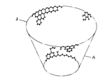
具体的には、CSCNT7は、図1,2に図示したような構造、即ち、炭素網Aの端部(カップの上縁部a)に多くの官能基(例えばカルボキシル基や水酸基)を有するユニット構造が複数積み重なった構造であり、上下端部だけでなく側周面にも官能基が存在することになるため、それだけ濡れ性に秀れることになる。従って、プリプレグ5と樹脂シート6とにCSCNT7を均一に分散させることが可能となり、CSCNT7が均一に分散することで以下の作用効果を生じる。
Specifically, the CSCNT 7 has a structure as shown in FIGS. 1 and 2, that is, a unit having many functional groups (for example, carboxyl groups and hydroxyl groups) at the end of the carbon network A (upper edge portion a of the cup). This is a structure in which a plurality of structures are stacked, and functional groups are present not only on the upper and lower ends but also on the side peripheral surface, so that the wettability is improved accordingly. Accordingly, the CSCNT 7 can be uniformly dispersed in the
(1) CSCNT7は、上記構造を有するため、繊維体3とマトリックス樹脂4との
間においてCSCNT7の端部が楔効果を発揮することで両者の結合が強固とな
り、これにより繊維体3間の層間せん断強度が向上する。
(1) Since CSCNT 7 has the above-described structure, the end of
(2) また、CSCNT7の各ユニット同士の間(各カップ状の炭素網Aの内周面b
及び外周面cの間)には間隙が存在し、これにより、外部から応力が加わった場
合、応力吸収が行われるため、座屈し難い。よって、複合材料とした場合に圧縮
強度が向上すると考えられる。
(2) Moreover, between each unit of CSCNT7 (inner peripheral surface b of each cup-shaped carbon net A)
And an outer peripheral surface c), there is a gap, and when stress is applied from the outside, stress absorption is performed, so that buckling is difficult. Therefore, it is considered that the compressive strength is improved when a composite material is used.
(3) 更に、例えばCSCNT7を含有させるプリプレグ5及び樹脂シート6に濃度
差を持たせることで、プリプレグ5と樹脂シート6とを積層して硬化成形により
樹脂が溶融した際、CSCNT7が高濃度側から低濃度側へと移動する。これに
より、上記楔効果をプリプレグ5と樹脂シート6との境界部分でも効率良く発現
させることが可能となる。
(3) Furthermore, for example, when the
(4) その上、例えばプリプレグ5のマトリックス樹脂4及び樹脂シート6の硬化性
樹脂の組成を同一とした場合には、複合材料中で相分離が生じ難くなり、それだ
け剥離強度を向上させることが可能となる。
(4) In addition, for example, when the composition of the matrix resin 4 of the
よって、本発明によれば、従来の複合材料に比し、層間せん断強度及び圧縮強度が大幅に向上した複合材料を実現可能となる。 Therefore, according to the present invention, it is possible to realize a composite material in which interlaminar shear strength and compressive strength are significantly improved as compared with conventional composite materials.
本発明の具体的な実施例について図面に基づいて説明する。 Specific embodiments of the present invention will be described with reference to the drawings.
本実施例は、複数の炭素フィラメント1を収束した炭素繊維束2を一方向に引き揃えた一方向繊維体3若しくは前記炭素繊維束2を経糸及び緯糸として織成した織成繊維体に、硬化性のマトリックス樹脂4を含浸させて構成されるプリプレグ5と、硬化性樹脂で構成される樹脂シート6とを交互に積層して成る複合材料であって、前記プリプレグ5のマトリックス樹脂4及び前記樹脂シート6の硬化性樹脂には、カップスタック型のCNT7が分散状態で含有されているものである。
In this example, a
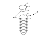
具体的には、図3に図示したように、繊維体として複数の炭素フィラメント1を収束した炭素繊維束2を一方向に引き揃えた一方向繊維体3が採用されており、この一方向繊維体3に熱硬化性のマトリックス樹脂4を含浸させることでUDPPが構成され、このUDPPを熱硬化性樹脂で構成される樹脂シート6を介して複数積層して加熱硬化せしめることで複合材料とする。尚、炭素繊維束2を経糸及び緯糸として織成して成る織成繊維体を用いても良い。また、硬化性樹脂として熱硬化性樹脂以外の樹脂を採用しても良い。
Specifically, as illustrated in FIG. 3, a
各部を具体的に説明する。 Each part will be specifically described.
プリプレグ5のマトリックス樹脂4及び樹脂シート6の熱硬化性樹脂に含有せしめられるカップスタック型のCNT7(CSCNT7)として、アスペクト比が2〜50に設定されているものが採用されている。これは、アスペクト比が2未満若しくは50を超えるとCSCNT構造を有効に活用できず、十分な力学的特性が発揮されないためである。
As the cup stack type CNT7 (CSCNT7) to be contained in the matrix resin 4 of the
また、CSCNT7の含有割合は、プリプレグ5のマトリックス樹脂4より前記樹脂シート6の硬化性樹脂の方が高く設定されている。
The content ratio of CSCNT 7 is set higher in the curable resin of the
これにより、加熱硬化の際に樹脂が溶融すると、CSCNT含有割合の高い(高濃度の)樹脂シート6側からCSCNT含有割合の低い(低濃度の)プリプレグ5側にCSCNT7が移動し、この際、溶融して一体化しつつあるプリプレグ5と樹脂シート6との境界部分にもCSCNT7が存在することになり、上記楔効果によりプリプレグ5と樹脂シート6との結合強度が強固となる。
Thereby, when the resin is melted during the heat curing, the
尚、マトリックス樹脂4には、このマトリックス樹脂4に対してCSCNT7が2〜10wt%含有されている。これは、2wt%以下になるとCSCNT構造の特性を有効に活用することができず、10wt%以上になると繊維体に樹脂を均一且つ十分に含浸させることができなくなり、十分な力学的特性が発揮されないためである。
The matrix resin 4 contains 2 to 10 wt% of
また、樹脂シート6の硬化性樹脂には、この硬化性樹脂に対してCSCNT7が10〜30wt%含有されている。これは、10wt%以下になるとCSCNT構造の特性を有効に活用することができず、30wt%以上になると樹脂との均一化が困難となるためである。
Further, the curable resin of the
また、プリプレグ5のマトリックス樹脂4及び前記樹脂シート6の熱硬化性樹脂は、同一の樹脂組成が採用されている。これにより、加熱硬化の際に相分離が起こり難く、それだけ剥離強度が向上する。
The matrix resin 4 of the
具体的には、熱硬化性樹脂としては以下のA〜Cから成る樹脂組成物を採用する。
A:主剤 ノボラック系エポキシ樹脂若しくはビスフェノールA型エポキシ樹脂
B:硬化剤 ジシアンジアミド(主剤を硬化させるものであれば特に制限はない。)
C:硬化促進剤 DCMU若しくはイミダゾール(主剤を硬化させるものであれば特に制
限はない。)
本実施例においては、ビスフェノールA型エポキシ樹脂とジシアンジアミドとDCMUとから成る樹脂組成物が採用されている。
Specifically, a resin composition composed of the following A to C is adopted as the thermosetting resin.
A: Main agent Novolac epoxy resin or bisphenol A type epoxy resin B: Curing agent Dicyandiamide (There is no particular limitation as long as the main agent is cured.)
C: Curing accelerator DCMU or imidazole (especially if it can cure the main agent)
There is no limit. )
In this example, a resin composition comprising bisphenol A type epoxy resin, dicyandiamide, and DCMU is employed.
以下、本実施例の作製方法について説明する。 Hereinafter, a manufacturing method of this example will be described.
樹脂シート6は、上記主剤にCSCNT7を添加して攪拌混合した後、上記硬化剤を添加して70〜80℃×0.5〜2hの条件で加熱攪拌し、更に、上記硬化促進剤を加えた後、70〜80℃×3〜10minの条件で加熱攪拌し、続いて、当該樹脂組成物を離型フィルム(図示省略)上に塗布し、厚さが20〜100μmのシート状となるように成形して作製される。尚、有機溶剤を適宜加えてもよい。具体的には本実施例では以下の手順で作製している。
The
(1) 上記主剤(100重量部)にCSCNT7(アスペクト比10)を全体樹脂量
に対して10wt%となるように添加して、攪拌混合する。
(1) CSCNT7 (aspect ratio 10) is added to the above main agent (100 parts by weight) so as to be 10 wt% with respect to the total resin amount, and the mixture is stirred and mixed.
(2) 攪拌混合後、(1)の樹脂組成物に上記硬化剤(4.5重量部)を添加する。
その後、75℃×0.5hで加熱しながら攪拌する。
(2) After stirring and mixing, the curing agent (4.5 parts by weight) is added to the resin composition of (1).
Then, it stirs, heating at 75 degreeC x 0.5h.
(3) (2)の樹脂組成物に上記硬化促進剤(3重量部)を加えた後、75℃×5m
inで更に加熱しながら攪拌する。
(3) After adding the curing accelerator (3 parts by weight) to the resin composition of (2), 75 ° C. × 5 m
Stir while further heating in.
(4) (3)の樹脂組成物を離型フィルム上に塗布し、厚さが50μmのシート状と
なるように成形する。
(4) The resin composition of (3) is applied on a release film and molded into a sheet having a thickness of 50 μm.
尚、プリプレグ5のマトリックス樹脂4となるプリプレグ用樹脂シートは、上記(1)のCSCNT7を全体樹脂量に対して5wt%となるように添加する点以外は、上記同様の手順で作製される。
The prepreg resin sheet to be the matrix resin 4 of the
プリプレグ5(UDPP)は、上述のようにして作製したプリプレグ用樹脂シート及び東レ製T−700SCを炭素繊維束2として採用し、FAW(単位面積当たりの繊維重量)=125g/m2の目付けの一方向繊維体3を用いて作製される。
The prepreg 5 (UDPP) employs the resin sheet for prepreg produced as described above and T-700SC manufactured by Toray as the
具体的には、一方向繊維体3の両面若しくは片面にプリプレグ用樹脂シートを積層し、この一方向繊維体3とプリプレグ用樹脂シートとから成る積層体を離型フィルムを介して80〜120℃×3〜10min×1〜10kgf/cm2で熱ラミネートすることで、プリプレグ5が作製される。
Specifically, a prepreg resin sheet is laminated on both sides or one side of the unidirectional
本実施例においては、一方向繊維体3の片面にプリプレグ用樹脂シートを積層し、この積層体を離型フィルムを介して100℃×5min×2〜4kgf/cm2で熱ラミネートすることでプリプレグ5を作製している。
In this embodiment, a prepreg resin sheet is laminated on one side of the
本実施例は、上述のようにして作製したUDPPと樹脂シート6とを所定の枚数積層した後(図3(a))、120〜150℃×0.5〜2h×1〜5kgf/cm2で硬化成形することで作製される(図3(b))。具体的には、130℃×1h×3kgf/cm2で硬化成形することで作製されている。
In this example, after a predetermined number of UDPPs prepared as described above and the
ここで、本実施例では、上述のようにプリプレグ5を樹脂シート6を介して積層し、且つ、プリプレグ5及び樹脂シート6の双方にCSCNT7を含有せしめ、更に、プリプレグ5より樹脂シート6のCSCNT7の含有割合を高くしているため、加熱されて図3(b)の状態となると、マトリックス樹脂4及び樹脂シート6の熱硬化性樹脂が溶融して境界が曖昧となり、樹脂シート6に含有されるCSCNT7がより低濃度側のプリプレグ5へ移動する。これにより、樹脂シート6は、樹脂シート6の中心部分でCSCNT7の濃度が最も高く、プリプレグ5側へ行くほど濃度が徐々に低くなる分布を有し、さらに樹脂シート6とプリプレグ5の境界部でCSCNT7が存在するため、CSCNT7の楔効果が効率よく発揮される。
Here, in this embodiment, as described above, the
よって、各層間の結合がそれだけ強固となり、層間せん断強度が大幅に向上することになる。また、CSCNT7は気相成長法により得られる従来のCNTに比し座屈しにくく、応力吸収などが良好に行われるため、圧縮強度も大幅に向上する。
Therefore, the bond between the layers becomes so strong that the interlayer shear strength is greatly improved. In addition,
しかも、プリプレグ5と樹脂シート6とを交互に積層させることで、マトリックス樹脂4にCSCNT7を多く含有させなくても、樹脂シート6に多めに含有させておくことで、繊維体へのマトリックス樹脂4の含浸を阻害することなく上記作用効果を得ることができる。
Moreover, by alternately laminating the
本実施例は上述のように構成したから、マトリックス樹脂4にCSCNT7が分散状態で含有されたプリプレグ5と、硬化性樹脂にCSCNT7が分散状態で含有された樹脂シート6とを交互に積層し、硬化成形して成る複合材料は、分散したCSCNT7により繊維体3とマトリックス樹脂4との結合及びプリプレグ5同士の結合が強固となり、硬化後の各プリプレグ5間において層間剥離が生じ難い。また、外部から応力が加わった場合、CSCNT7により応力吸収が行われるため、座屈し難く、圧縮強度が向上する。更に、マトリックス樹脂4及び樹脂シート6の硬化性樹脂の組成を同一としたから、複合材料中で相分離が生じ難くなり、それだけ剥離強度を向上する。
Since this example is configured as described above, the
よって、本実施例は、従来の複合材料に比し、層間せん断強度及び圧縮強度を十分に向上させることが可能な極めて実用性に秀れた複合材料となる。 Therefore, this embodiment is a composite material that is extremely practical and capable of sufficiently improving the interlaminar shear strength and the compressive strength as compared with the conventional composite material.
本実施例の効果を裏付ける実験例について説明する。 An experimental example supporting the effect of the present embodiment will be described.
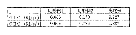
実験例では、上述のようにUDPP及び樹脂シートにCSCNTを含有させた実施例と、UDPP及び樹脂シートにCSCNTを含有させない比較例1と、UDPPにCSCNTを含有させ樹脂シートにはCSCNTを含有させない比較例2のGIC及びGIICを測定し、比較した。図4に実験結果を示す。GIC及びGIICは共にJIS K7086に準拠して測定した。尚、測定用試料は、上下の最外層がUDPPとなるように8枚のUDPPと7枚の樹脂シートとを交互に積層し、硬化成形して得たものである。また、UDPPの繊維引き揃え方向は各層同一方向(0°方向)とした。 In the experimental example, as described above, the UDPP and the resin sheet were made to contain CSCNT, the comparative example 1 in which the UDPP and the resin sheet were not made to contain CSCNT, and the UDPP was made to contain CSCNT and the resin sheet was not made to contain CSCNT. The GIC and GIIC of Comparative Example 2 were measured and compared. FIG. 4 shows the experimental results. Both GIC and GIIC were measured according to JIS K7086. The measurement sample was obtained by alternately laminating eight UDPPs and seven resin sheets so that the upper and lower outermost layers are UDPP, and curing and molding them. The fiber alignment direction of UDPP was the same direction (0 ° direction) for each layer.
実験結果から、プリプレグ及び樹脂シートの双方にCSCNTを含有させることで、GIC及びGIICの著しい向上が認められた。このように直接的な開口破壊靱性が著しく向上した報告例は今までに無い。従って、層間せん断強度(ILSS)及び圧縮強度も著しく向上するものと想定される。 From the experimental results, it was confirmed that GIC and GIIC were significantly improved by containing CSCNT in both the prepreg and the resin sheet. There has been no report so far in which the direct opening fracture toughness has been remarkably improved. Therefore, it is assumed that the interlaminar shear strength (ILSS) and compressive strength are also significantly improved.
1 炭素フィラメント
2 炭素繊維束
3 一方向繊維体
4 マトリックス樹脂
5 プリプレグ
6 樹脂シート
7 カップスタック型のCNT
DESCRIPTION OF SYMBOLS 1
Claims (4)
Priority Applications (3)
| Application Number | Priority Date | Filing Date | Title |
|---|---|---|---|
| JP2007178203A JP5117779B2 (en) | 2007-07-06 | 2007-07-06 | Composite material |
| PCT/JP2008/062019 WO2009008312A1 (en) | 2007-07-06 | 2008-07-02 | Composite material |
| TW097125566A TW200916513A (en) | 2007-07-06 | 2008-07-07 | Composite material |
Applications Claiming Priority (1)
| Application Number | Priority Date | Filing Date | Title |
|---|---|---|---|
| JP2007178203A JP5117779B2 (en) | 2007-07-06 | 2007-07-06 | Composite material |
Publications (2)
| Publication Number | Publication Date |
|---|---|
| JP2009013327A JP2009013327A (en) | 2009-01-22 |
| JP5117779B2 true JP5117779B2 (en) | 2013-01-16 |
Family
ID=40228490
Family Applications (1)
| Application Number | Title | Priority Date | Filing Date |
|---|---|---|---|
| JP2007178203A Active JP5117779B2 (en) | 2007-07-06 | 2007-07-06 | Composite material |
Country Status (3)
| Country | Link |
|---|---|
| JP (1) | JP5117779B2 (en) |
| TW (1) | TW200916513A (en) |
| WO (1) | WO2009008312A1 (en) |
Families Citing this family (13)
| Publication number | Priority date | Publication date | Assignee | Title |
|---|---|---|---|---|
| EP2513250A4 (en) * | 2009-12-14 | 2015-05-27 | Applied Nanostructured Sols | Flame-resistant composite materials and articles containing carbon nanotube-infused fiber materials |
| KR101305072B1 (en) * | 2009-12-30 | 2013-09-11 | 제일모직주식회사 | Carbon nanofiber-metal composite and method for preparing the same |
| KR101906262B1 (en) | 2010-02-02 | 2018-10-10 | 어플라이드 나노스트럭처드 솔루션스, 엘엘씨. | Fiber containing parallel-aligned carbon nanotubes |
| US9017854B2 (en) | 2010-08-30 | 2015-04-28 | Applied Nanostructured Solutions, Llc | Structural energy storage assemblies and methods for production thereof |
| TWI509119B (en) | 2012-12-03 | 2015-11-21 | Ind Tech Res Inst | Carbon fiber composite and manufacturing method thereof |
| WO2016159072A1 (en) * | 2015-03-31 | 2016-10-06 | 国立研究開発法人産業技術総合研究所 | Method for producing carbon fiber composite material |
| JP2018016030A (en) * | 2016-07-29 | 2018-02-01 | 学校法人幾徳学園 | Carbon fiber-reinforced plastic and method for producing the same |
| CN109676951B (en) | 2017-10-18 | 2021-03-09 | 财团法人工业技术研究院 | Fiber composite material and method for making the same |
| US10272651B1 (en) | 2017-10-18 | 2019-04-30 | Industrial Technology Research Institute | Fiber composite and manufacturing method thereof |
| WO2020111091A1 (en) * | 2018-11-28 | 2020-06-04 | 三菱ケミカル株式会社 | Cloth prepreg, method for manufacturing cloth prepreg, fiber reinforced resin molded article, and method for manufacturing fiber reinforced resin molded article |
| CN111805935B (en) | 2019-04-11 | 2022-01-07 | 财团法人工业技术研究院 | Fiber composite structure |
| CN112590252A (en) * | 2020-11-27 | 2021-04-02 | 哈尔滨工业大学 | Method for enhancing interlayer performance of thermoplastic automatic laying component |
| CN114347502A (en) * | 2022-01-05 | 2022-04-15 | 泰山玻璃纤维有限公司 | Carbon-glass mixed pulling plate based on bulked yarn modification and production process thereof |
Family Cites Families (7)
| Publication number | Priority date | Publication date | Assignee | Title |
|---|---|---|---|---|
| EP0133280A3 (en) * | 1983-08-01 | 1986-03-19 | American Cyanamid Company | Thermoset interleafed resin matrix composites with improved compression properties |
| ATE58503T1 (en) * | 1984-03-30 | 1990-12-15 | American Cyanamid Co | HIGH IMPACT RESISTANCE FIBROLOGICAL MATRIX COMPOSITIONS. |
| JPS6265212U (en) * | 1985-10-16 | 1987-04-23 | ||
| JPS63162733A (en) * | 1986-12-26 | 1988-07-06 | Ube Ind Ltd | Fiber reinforced epoxy resin prepreg with interleaf |
| JPH04267139A (en) * | 1991-02-22 | 1992-09-22 | Nec Corp | Carbon fiber reinforced composite material prepreg sheet |
| JP4273092B2 (en) * | 2005-03-30 | 2009-06-03 | 株式会社Gsiクレオス | Prepreg manufacturing method and prepreg manufacturing apparatus |
| JP4156620B2 (en) * | 2005-10-07 | 2008-09-24 | 株式会社Gsiクレオス | Prepreg manufacturing apparatus and prepreg |
-
2007
- 2007-07-06 JP JP2007178203A patent/JP5117779B2/en active Active
-
2008
- 2008-07-02 WO PCT/JP2008/062019 patent/WO2009008312A1/en not_active Ceased
- 2008-07-07 TW TW097125566A patent/TW200916513A/en unknown
Also Published As
| Publication number | Publication date |
|---|---|
| TW200916513A (en) | 2009-04-16 |
| WO2009008312A1 (en) | 2009-01-15 |
| JP2009013327A (en) | 2009-01-22 |
Similar Documents
| Publication | Publication Date | Title |
|---|---|---|
| JP5117779B2 (en) | Composite material | |
| JP3894035B2 (en) | Carbon fiber reinforced substrate, preform and composite material comprising the same | |
| US8283403B2 (en) | Carbon nanotube-reinforced nanocomposites | |
| KR102006511B1 (en) | Composite laminate having improved impact strength and the use thereof | |
| US7407901B2 (en) | Impact resistant, thin ply composite structures and method of manufacturing same | |
| CN104736614B (en) | Fiber reinforcement high modulus polymer complex with enhancing interface phase | |
| US20140322504A1 (en) | Carbon fiber base, prepreg and carbon-fiber-reinforced composite material | |
| JP5228853B2 (en) | Epoxy resin composition, fiber reinforced composite material, and production method thereof | |
| CN104884511B (en) | Fiber-reinforced polymer complex with hard interface phase | |
| KR101659591B1 (en) | Method for manufacturing hybrid ceramic fiber reinforced composite material and hybrid ceramic fiber reinforced composite material manufactured thereby | |
| KR20200079313A (en) | Composite having interlayer toughened particles and method for manufacturing same | |
| JP4233560B2 (en) | Manufacturing method of prepreg | |
| KR102317967B1 (en) | Carbon fiber reinforced composite reinforced with aramid nanofibers and method for manufacturing the same | |
| US5116668A (en) | Hybrid yarn, unidirectional hybrid prepreg and laminated material thereof | |
| JP2018118440A (en) | Draw-out body and method for producing | |
| Ren et al. | Hybrid effect on mechanical properties of M40‐T300 carbon fiber reinforced Bisphenol A Dicyanate ester composites | |
| JP4687167B2 (en) | Epoxy resin composition, prepreg and fiber reinforced composite material | |
| JPH0232843A (en) | Intermediate body of molded product and molded product | |
| US12024606B2 (en) | Composite prepreg, preform using the same, fiber-reinforced composite material assembly, and method for producing the same | |
| JP2008174610A (en) | Impact resistant prepreg and method for producing the same | |
| JP2014162858A (en) | Prepreg and production method of the same, and fiber reinforced composite material | |
| JP2010059300A (en) | Carbon fiber reinforced composite material and method for producing the same | |
| JP2006198920A (en) | Pre-preg for honeycomb cocure, honeycomb laminated composite and production method thereof | |
| KR20180029805A (en) | Cold hardening epoxy resin using the composition and prepreg, and prepreg to make it into a layer of polymer composite | |
| KR102461792B1 (en) | Tow prepreg having high impact strength for the filament winding |
Legal Events
| Date | Code | Title | Description |
|---|---|---|---|
| A131 | Notification of reasons for refusal |
Free format text: JAPANESE INTERMEDIATE CODE: A131 Effective date: 20101220 |
|
| A521 | Request for written amendment filed |
Free format text: JAPANESE INTERMEDIATE CODE: A523 Effective date: 20110218 |
|
| A131 | Notification of reasons for refusal |
Free format text: JAPANESE INTERMEDIATE CODE: A131 Effective date: 20111221 |
|
| A521 | Request for written amendment filed |
Free format text: JAPANESE INTERMEDIATE CODE: A821 Effective date: 20120220 |
|
| TRDD | Decision of grant or rejection written | ||
| A01 | Written decision to grant a patent or to grant a registration (utility model) |
Free format text: JAPANESE INTERMEDIATE CODE: A01 Effective date: 20120920 |
|
| A01 | Written decision to grant a patent or to grant a registration (utility model) |
Free format text: JAPANESE INTERMEDIATE CODE: A01 |
|
| A61 | First payment of annual fees (during grant procedure) |
Free format text: JAPANESE INTERMEDIATE CODE: A61 Effective date: 20121018 |
|
| R150 | Certificate of patent or registration of utility model |
Ref document number: 5117779 Country of ref document: JP Free format text: JAPANESE INTERMEDIATE CODE: R150 Free format text: JAPANESE INTERMEDIATE CODE: R150 |
|
| FPAY | Renewal fee payment (event date is renewal date of database) |
Free format text: PAYMENT UNTIL: 20151026 Year of fee payment: 3 |
|
| R250 | Receipt of annual fees |
Free format text: JAPANESE INTERMEDIATE CODE: R250 |
|
| R250 | Receipt of annual fees |
Free format text: JAPANESE INTERMEDIATE CODE: R250 |
|
| R250 | Receipt of annual fees |
Free format text: JAPANESE INTERMEDIATE CODE: R250 |
|
| R250 | Receipt of annual fees |
Free format text: JAPANESE INTERMEDIATE CODE: R250 |
|
| R250 | Receipt of annual fees |
Free format text: JAPANESE INTERMEDIATE CODE: R250 |
|
| R250 | Receipt of annual fees |
Free format text: JAPANESE INTERMEDIATE CODE: R250 |
|
| R250 | Receipt of annual fees |
Free format text: JAPANESE INTERMEDIATE CODE: R250 |
|
| R250 | Receipt of annual fees |
Free format text: JAPANESE INTERMEDIATE CODE: R250 |
|
| R250 | Receipt of annual fees |
Free format text: JAPANESE INTERMEDIATE CODE: R250 |
|
| R250 | Receipt of annual fees |
Free format text: JAPANESE INTERMEDIATE CODE: R250 |
|
| R250 | Receipt of annual fees |
Free format text: JAPANESE INTERMEDIATE CODE: R250 |