JP5115543B2 - Installation structure of electric motor for hybrid vehicle - Google Patents
Installation structure of electric motor for hybrid vehicle Download PDFInfo
- Publication number
- JP5115543B2 JP5115543B2 JP2009275770A JP2009275770A JP5115543B2 JP 5115543 B2 JP5115543 B2 JP 5115543B2 JP 2009275770 A JP2009275770 A JP 2009275770A JP 2009275770 A JP2009275770 A JP 2009275770A JP 5115543 B2 JP5115543 B2 JP 5115543B2
- Authority
- JP
- Japan
- Prior art keywords
- rear wheel
- motor
- vehicle
- wheel motor
- cross member
- Prior art date
- Legal status (The legal status is an assumption and is not a legal conclusion. Google has not performed a legal analysis and makes no representation as to the accuracy of the status listed.)
- Active
Links
Images


Classifications
-
- B—PERFORMING OPERATIONS; TRANSPORTING
- B60—VEHICLES IN GENERAL
- B60K—ARRANGEMENT OR MOUNTING OF PROPULSION UNITS OR OF TRANSMISSIONS IN VEHICLES; ARRANGEMENT OR MOUNTING OF PLURAL DIVERSE PRIME-MOVERS IN VEHICLES; AUXILIARY DRIVES FOR VEHICLES; INSTRUMENTATION OR DASHBOARDS FOR VEHICLES; ARRANGEMENTS IN CONNECTION WITH COOLING, AIR INTAKE, GAS EXHAUST OR FUEL SUPPLY OF PROPULSION UNITS IN VEHICLES
- B60K1/00—Arrangement or mounting of electrical propulsion units
-
- B—PERFORMING OPERATIONS; TRANSPORTING
- B60—VEHICLES IN GENERAL
- B60K—ARRANGEMENT OR MOUNTING OF PROPULSION UNITS OR OF TRANSMISSIONS IN VEHICLES; ARRANGEMENT OR MOUNTING OF PLURAL DIVERSE PRIME-MOVERS IN VEHICLES; AUXILIARY DRIVES FOR VEHICLES; INSTRUMENTATION OR DASHBOARDS FOR VEHICLES; ARRANGEMENTS IN CONNECTION WITH COOLING, AIR INTAKE, GAS EXHAUST OR FUEL SUPPLY OF PROPULSION UNITS IN VEHICLES
- B60K5/00—Arrangement or mounting of internal-combustion or jet-propulsion units
- B60K5/12—Arrangement of engine supports
- B60K5/1241—Link-type support
-
- B—PERFORMING OPERATIONS; TRANSPORTING
- B60—VEHICLES IN GENERAL
- B60K—ARRANGEMENT OR MOUNTING OF PROPULSION UNITS OR OF TRANSMISSIONS IN VEHICLES; ARRANGEMENT OR MOUNTING OF PLURAL DIVERSE PRIME-MOVERS IN VEHICLES; AUXILIARY DRIVES FOR VEHICLES; INSTRUMENTATION OR DASHBOARDS FOR VEHICLES; ARRANGEMENTS IN CONNECTION WITH COOLING, AIR INTAKE, GAS EXHAUST OR FUEL SUPPLY OF PROPULSION UNITS IN VEHICLES
- B60K17/00—Arrangement or mounting of transmissions in vehicles
- B60K17/34—Arrangement or mounting of transmissions in vehicles for driving both front and rear wheels, e.g. four wheel drive vehicles
- B60K17/356—Arrangement or mounting of transmissions in vehicles for driving both front and rear wheels, e.g. four wheel drive vehicles having fluid or electric motor, for driving one or more wheels
-
- B—PERFORMING OPERATIONS; TRANSPORTING
- B60—VEHICLES IN GENERAL
- B60K—ARRANGEMENT OR MOUNTING OF PROPULSION UNITS OR OF TRANSMISSIONS IN VEHICLES; ARRANGEMENT OR MOUNTING OF PLURAL DIVERSE PRIME-MOVERS IN VEHICLES; AUXILIARY DRIVES FOR VEHICLES; INSTRUMENTATION OR DASHBOARDS FOR VEHICLES; ARRANGEMENTS IN CONNECTION WITH COOLING, AIR INTAKE, GAS EXHAUST OR FUEL SUPPLY OF PROPULSION UNITS IN VEHICLES
- B60K1/00—Arrangement or mounting of electrical propulsion units
- B60K2001/001—Arrangement or mounting of electrical propulsion units one motor mounted on a propulsion axle for rotating right and left wheels of this axle
-
- B—PERFORMING OPERATIONS; TRANSPORTING
- B60—VEHICLES IN GENERAL
- B60K—ARRANGEMENT OR MOUNTING OF PROPULSION UNITS OR OF TRANSMISSIONS IN VEHICLES; ARRANGEMENT OR MOUNTING OF PLURAL DIVERSE PRIME-MOVERS IN VEHICLES; AUXILIARY DRIVES FOR VEHICLES; INSTRUMENTATION OR DASHBOARDS FOR VEHICLES; ARRANGEMENTS IN CONNECTION WITH COOLING, AIR INTAKE, GAS EXHAUST OR FUEL SUPPLY OF PROPULSION UNITS IN VEHICLES
- B60K1/00—Arrangement or mounting of electrical propulsion units
- B60K1/04—Arrangement or mounting of electrical propulsion units of the electric storage means for propulsion
- B60K2001/0405—Arrangement or mounting of electrical propulsion units of the electric storage means for propulsion characterised by their position
- B60K2001/0438—Arrangement under the floor
-
- B—PERFORMING OPERATIONS; TRANSPORTING
- B60—VEHICLES IN GENERAL
- B60K—ARRANGEMENT OR MOUNTING OF PROPULSION UNITS OR OF TRANSMISSIONS IN VEHICLES; ARRANGEMENT OR MOUNTING OF PLURAL DIVERSE PRIME-MOVERS IN VEHICLES; AUXILIARY DRIVES FOR VEHICLES; INSTRUMENTATION OR DASHBOARDS FOR VEHICLES; ARRANGEMENTS IN CONNECTION WITH COOLING, AIR INTAKE, GAS EXHAUST OR FUEL SUPPLY OF PROPULSION UNITS IN VEHICLES
- B60K15/00—Arrangement in connection with fuel supply of combustion engines or other fuel consuming energy converters, e.g. fuel cells; Mounting or construction of fuel tanks
- B60K15/03—Fuel tanks
- B60K15/063—Arrangement of tanks
- B60K2015/0633—Arrangement of tanks the fuel tank is arranged below the rear seat
-
- B—PERFORMING OPERATIONS; TRANSPORTING
- B60—VEHICLES IN GENERAL
- B60K—ARRANGEMENT OR MOUNTING OF PROPULSION UNITS OR OF TRANSMISSIONS IN VEHICLES; ARRANGEMENT OR MOUNTING OF PLURAL DIVERSE PRIME-MOVERS IN VEHICLES; AUXILIARY DRIVES FOR VEHICLES; INSTRUMENTATION OR DASHBOARDS FOR VEHICLES; ARRANGEMENTS IN CONNECTION WITH COOLING, AIR INTAKE, GAS EXHAUST OR FUEL SUPPLY OF PROPULSION UNITS IN VEHICLES
- B60K15/00—Arrangement in connection with fuel supply of combustion engines or other fuel consuming energy converters, e.g. fuel cells; Mounting or construction of fuel tanks
- B60K15/03—Fuel tanks
- B60K15/063—Arrangement of tanks
- B60K2015/0634—Arrangement of tanks the fuel tank is arranged below the vehicle floor
-
- B—PERFORMING OPERATIONS; TRANSPORTING
- B60—VEHICLES IN GENERAL
- B60K—ARRANGEMENT OR MOUNTING OF PROPULSION UNITS OR OF TRANSMISSIONS IN VEHICLES; ARRANGEMENT OR MOUNTING OF PLURAL DIVERSE PRIME-MOVERS IN VEHICLES; AUXILIARY DRIVES FOR VEHICLES; INSTRUMENTATION OR DASHBOARDS FOR VEHICLES; ARRANGEMENTS IN CONNECTION WITH COOLING, AIR INTAKE, GAS EXHAUST OR FUEL SUPPLY OF PROPULSION UNITS IN VEHICLES
- B60K15/00—Arrangement in connection with fuel supply of combustion engines or other fuel consuming energy converters, e.g. fuel cells; Mounting or construction of fuel tanks
- B60K15/03—Fuel tanks
- B60K15/063—Arrangement of tanks
- B60K2015/0638—Arrangement of tanks the fuel tank is arranged in the rear of the vehicle
-
- B—PERFORMING OPERATIONS; TRANSPORTING
- B60—VEHICLES IN GENERAL
- B60Y—INDEXING SCHEME RELATING TO ASPECTS CROSS-CUTTING VEHICLE TECHNOLOGY
- B60Y2306/00—Other features of vehicle sub-units
- B60Y2306/01—Reducing damages in case of crash, e.g. by improving battery protection
-
- B—PERFORMING OPERATIONS; TRANSPORTING
- B62—LAND VEHICLES FOR TRAVELLING OTHERWISE THAN ON RAILS
- B62D—MOTOR VEHICLES; TRAILERS
- B62D21/00—Understructures, i.e. chassis frame on which a vehicle body may be mounted
- B62D21/11—Understructures, i.e. chassis frame on which a vehicle body may be mounted with resilient means for suspension, e.g. of wheels or engine; sub-frames for mounting engine or suspensions
Description
本発明は、ハイブリッド車における後輪に連結させた電動機の取付構造に関する。 The present invention relates to a mounting structure for an electric motor connected to a rear wheel in a hybrid vehicle.
FF車(フロントエンジン・フロントドライブ車)の後輪に電動機を連結させ、エンジンと電動機で走行を可能としたFF車主体のハイブリッド車が知られている。FF車では、燃料タンクを後席の下部に配置し、室内空間や収容スペースを広く確保する構成が知られている。一方後輪に電動機を連結させる例としては、後輪の近傍に電動機を設置し、構造の簡略化や伝達効率を向上させた構成が考えられる。 2. Description of the Related Art Hybrid vehicles based on FF vehicles are known in which an electric motor is connected to the rear wheels of an FF vehicle (front engine / front drive vehicle) so that the engine and the electric motor can run. In the FF vehicle, a configuration is known in which a fuel tank is arranged in the lower part of the rear seat to ensure a wide indoor space and accommodation space. On the other hand, as an example of connecting the electric motor to the rear wheel, a configuration in which the electric motor is installed in the vicinity of the rear wheel to simplify the structure and improve the transmission efficiency can be considered.
そのためFF車を主体として後輪に電動機を連結したハイブリッド車の場合、電動機の直前に燃料タンクが配置される構成が考えられる。 For this reason, in the case of a hybrid vehicle in which an electric motor is connected to the rear wheels, mainly an FF vehicle, a configuration in which a fuel tank is disposed immediately before the electric motor is conceivable.
ところが上記構成のハイブリッド車では、万一後方から衝突される(以下、「後突」とする。)と、後突により電動機が前方に押し出され、燃料タンクを破損させてしまうおそれが考えられる。 However, in the hybrid vehicle having the above-described configuration, if a collision occurs from the rear (hereinafter referred to as “rear collision”), the electric motor is pushed forward by the rear collision, and the fuel tank may be damaged.
本発明は、上記課題を解決し、車両後部に電動機を配置したハイブリッド車において、後突時に電動機が押し出されても燃料タンクへの損傷を生じさせない電動機の取付構造を提供することを目的とする。 An object of the present invention is to solve the above-described problems and provide an electric motor mounting structure that does not cause damage to a fuel tank even if the electric motor is pushed out at the time of a rear collision in a hybrid vehicle in which an electric motor is arranged at the rear of the vehicle. .
上記の課題を解決するため、本発明は、ハイブリッド車における電動機の取付構造を次のように構成した。 In order to solve the above-described problems, the present invention has the following motor mounting structure in a hybrid vehicle.
ハイブリッド車は、FF車(フロントエンジン・フロントドライブ車)の後輪に、電動機を連結させた構成を有している。車両は、後方に、井桁状のサブフレームを備えている。例えばサブフレームは、前後延設部材を左右に配置し、前後延設部材の前後にそれぞれフロントクロスメンバおよびリアクロスメンバを取り付けて、井桁状に形成されている。サブフレームには、リアの懸架装置などが組み付けられ、懸架装置を介して後輪を上下動自在に保持してもよい。またサブフレームの後方には、構造部材であるリアモータマウントを取り付ける。 The hybrid vehicle has a configuration in which an electric motor is connected to the rear wheel of an FF vehicle (front engine / front drive vehicle). The vehicle includes a cross beam-like subframe at the rear. For example, the subframe is formed in a cross beam shape by arranging front and rear extending members on the left and right sides, and attaching a front cross member and a rear cross member on the front and rear sides of the front and rear extending members, respectively. A rear suspension device or the like may be assembled to the subframe, and the rear wheel may be held so as to be movable up and down via the suspension device. A rear motor mount, which is a structural member, is attached to the rear of the subframe.
電動機は、サブフレームの内側、つまり左右の前後延設部材、フロントクロスメンバ、リアクロスメンバおよびリアモータマウントで囲まれた空間内に取り付ける。 The electric motor is mounted inside the subframe, that is, in a space surrounded by the left and right front-rear extending members, the front cross member, the rear cross member, and the rear motor mount.
具体的には、電動機は次のように取り付ける。フロントクロスメンバに、連結部材(フロントモータマウント)を取り付けるブラケット(フロントモータマウントブラケット)を設ける。フロントモータマウントは、前方にマウント部を有し、後方にマウント部と一体に形成された取付部を有している。フロントモータマウントのマウント部をブラケットに取り付け、取付部を後輪電動機に取り付ける。これにより、後輪電動機をサブフレームに固定する。 Specifically, the electric motor is attached as follows. A bracket (front motor mount bracket) for attaching a connecting member (front motor mount) is provided on the front cross member. The front motor mount has a mounting portion at the front and an attachment portion formed integrally with the mounting portion at the rear. Attach the front motor mount to the bracket and attach the mounting to the rear wheel motor. As a result, the rear wheel motor is fixed to the subframe.
またリアクロスメンバを、後輪電動機の下方に、後輪電動機との間に若干の間隙をもって通す。リアモータマウントを、後輪電動機の後方に、後輪電動機との間に若干の間隙をもって通るように取り付ける。リアモータマウントの両端は、リアクロスメンバの左右端部に取り付ける。更に後輪電動機は、フロントモータマウントのマウント部の中心より若干高い位置にしてサブフレームに取り付ける。燃料タンクは、フロントクロスメンバの前方に、フロントクロスメンバとほぼ同じ高さに、フロントクロスメンバとの間に若干の間隙をもって配置する。 Further, the rear cross member is passed under the rear wheel motor with a slight gap between the rear cross member and the rear wheel motor. The rear motor mount is attached behind the rear wheel motor so as to pass through with a slight gap between the rear motor mount and the rear wheel motor. Both ends of the rear motor mount are attached to the left and right ends of the rear cross member. Further, the rear wheel motor is attached to the subframe at a position slightly higher than the center of the mount portion of the front motor mount. The fuel tank is disposed in front of the front cross member at substantially the same height as the front cross member with a slight gap between the fuel tank and the front cross member.
本発明にかかる電動機の取付構造は、次の効果を有している。後輪電動機が後輪の近傍に設けられているので、後輪を効率よく駆動して車両を走行させることができる。そして万一車両が後突された場合には、リアモータマウントが追突車両からの衝撃を受け止める。リアモータマウントと後輪電動機との間には間隔が設けられているので、後輪電動機に破損が生じない。 The motor mounting structure according to the present invention has the following effects. Since the rear wheel motor is provided in the vicinity of the rear wheel, the vehicle can be driven by efficiently driving the rear wheel. In the unlikely event that the vehicle is impacted rearward, the rear motor mount receives the impact from the rear-end collision vehicle. Since a gap is provided between the rear motor mount and the rear wheel motor, the rear wheel motor is not damaged.
後突エネルギーが大きく、リアモータマウントやリアクロスメンバが変形した場合には、後輪電動機が前方に押され、フロントモータマウントが折損する。しかし後輪電動機は、前方に設けられたフロントクロスメンバに移動が遮られ、斜め下方に押し出される。 When the rear impact energy is large and the rear motor mount or the rear cross member is deformed, the rear wheel motor is pushed forward, and the front motor mount is broken. However, the movement of the rear wheel motor is blocked by a front cross member provided at the front, and is pushed obliquely downward.
これにより、後輪電動機が後方から押圧されても、燃料タンクに当接することがなく移動する。したがって、後輪電動機による燃料タンクの破損を確実に防止できる。更に、フロントモータマウントが折損しても、後輪電動機はリアクロスメンバ上に載置され、後輪電動機が車両から完全に脱落してしまうことは防止される。 Thereby, even if the rear wheel motor is pressed from behind, the rear wheel motor moves without coming into contact with the fuel tank. Therefore, it is possible to reliably prevent the fuel tank from being damaged by the rear wheel motor. Furthermore, even if the front motor mount is broken, the rear wheel motor is placed on the rear cross member, and the rear wheel motor is prevented from falling off the vehicle completely.
本発明にかかる、ハイブリッド車における電動機の取付構造の一実施形態について説明する。 An embodiment of a motor mounting structure in a hybrid vehicle according to the present invention will be described.
図5に、ハイブリッド車としての車両10を示す。車両10は、前方にエンジン12を搭載し、後方に走行用の後輪電動機14、および燃料タンク22を備えている。以下、車両10の進行方向を前方とし、その逆を後方とし、それを基準に左右を定め、更に重力の方向を下方とし、その逆を上方として説明する。
FIG. 5 shows a
車両10は、前方左右に前輪16、後方左右に後輪18をそれぞれ具えている。エンジン12は、ガソリンを燃料とする内燃機関で、左右の前輪16の間に搭載されている。エンジン12には、変速機、差動機構(いずれも図示せず。)などが組み付けられており、エンジン12の回転出力がこれらを介して前輪16に伝達される。
The
車両10は、ECU(電子コントロールユニット)(図示せず。)を備えている。ECUは、アクセルペダルやブレーキペダル(いずれも図示せず。)の操作状態、車速、後述する電池30の充電量等各種情報を入手し、これらの値に基づきエンジン12や変速機等を適宜制御する。尚エンジン12は、ガソリンエンジンに限るものではない。
The
エンジン12の側方には、発電機20が設けられている。発電機20は、エンジン12や前輪16から入力される回転力により発電する。車両10の床下中央部分には、電池30が設けられている。電池30は、車両10を走行させる電池であり、比較的大きな容量を有している。発電機20で発電された電力は、電池30に蓄えられる。尚発電機20は、電池30からの電力により駆動し、前輪16を回転させたり、エンジン12の始動を行わせるように構成してもよい。車両10の後方には、内側に後輪電動機14を組み付けたサブフレーム50が設けられている。
A
次に、サブフレーム50について説明する。
Next, the
図2に、サブフレーム50を示す。図2に示すようにサブフレーム50は井桁状で、左右両側に設けられたメインパイプとしての管状部材52、54(前後延設部材)と、管状部材52、54の前方に設けられたフロントクロスメンバ56(前側左右延設部材)と、後方に設けられたリアクロスメンバ58(後側左右延設部材)などから形成されている。
FIG. 2 shows a
フロントクロスメンバ56は、断面四角形の部材で、車両10の幅方向に設けられている。フロントクロスメンバ56には、管状部材52、54の先端部分が所定の間隔をもって固定されている。またフロントクロスメンバ56の左右両端には、固定部60が形成してある。固定部60は、車両10のシャーシフレーム35(図5参照。)に固定される。
The
更にフロントクロスメンバ56のほぼ中央には、フロントモータマウントブラケット62が設けられている。フロントモータマウントブラケット62は、ほぼコの字状に形成されており、フロントクロスメンバ56の下方に延びている。フロントモータマウントブラケット62の内側には、連結部材としてのフロントモータマウント64が取り付けられる。
Further, a front
フロントモータマウント64を、図3に示す。フロントモータマウント64は、図3に示すように、基台66と基台66に設けられた取付部としての取付片68から形成されている。基台66にはマウント部70が形成してあり、マウント部70がフロントモータマウントブラケット62に取り付けられる。取付片68は、ほぼ三角形の板状部材であり、3箇所の角部にそれぞれ取付孔71が形成されている。
The
管状部材52と54は、管状部材からなり、図2に示すようにそれぞれが車両10の前後方向に対してほぼ左右対称に形成されている。管状部材52および54は、フロントクロスメンバ56から、フロントクロスメンバ56とほぼ同一の高さを保持した状態で後方に延び、中間付近で外方に開くように湾曲している。そして管状部材52、54の後端は、それぞれリアクロスメンバ58の左右端部に連結されている。
The
管状部材52および54とリアクロスメンバ58との連結部分には、固定部72が形成してある。固定部72は、車両10のシャーシフレーム35(図5参照。)に固定される。
A fixing
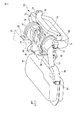
リアクロスメンバ58は、断面四角形の部材で、左右両端が上方に湾曲し、両端で管状部材52、54と連結している。リアクロスメンバ58の中央部分は、若干前方に張り出している。リアクロスメンバ58の左右両端の後面には、取付部74が設けられている。取付部74には、図1に示すように構造部材としてのリアモータマウント76がねじで固定される。
The
図1に、サブフレーム50の内側に後輪電動機14を組み付けた状態を示す。後輪電動機14は、円筒体状で、出力軸(図示せず。)の方向を、車両10の幅方向と平行にして取り付けられている。
FIG. 1 shows a state in which the
後輪電動機14は、上部に端子連結部24を具えている。端子連結部24は、所定の数の接続端子(図示せず。)を有する接続口で、リアモータマウント76の後方壁より前方に配置されている。端子連結部24には、電力線34の一端が接続されている。電力線34は、直径が1cm程度であり、所定の電流を流すに十分な太さを有している。電力線34の他端は、後述するパワーコントロールユニット32に接続されている。端子連結部24に接続された電力線34は、端子連結部24から上方に湾曲し、パワーコントロールユニット32の接続口36に連結されている。接続口36は、後輪電動機14の端子連結部24と同様、リアモータマウント76の後方壁より前方に配置されている。
The
後輪電動機14の出力軸端面(図における右側面)には、減速差動機構38が設けられている。減速差動機構38は、内部に減速歯車と差動歯車とを具え、差動歯車の出力端部に左右の後輪駆動軸(図示せず。)が連結されている。後輪駆動軸はそれぞれ後輪18に連結され、後輪電動機14の回転出力を左右の後輪18に、差動を行いつつ伝達させている。尚、減速差動機構38には、減速でなく、増速歯車を内部に具えていてもよい。
A
減速差動機構38は、左側面に取付孔(図示せず。)を有し、取付孔を介して図4に示すようにフロントモータマウント64の取付片68がねじ73で固定されている。後輪電動機14は、これによりフロントクロスメンバ56に取り付けられている。
The
後輪電動機14は、リアモータマウント76と後輪電動機14の回転中心とをほぼ同じ高さにして取り付けられている。フロントクロスメンバ56の前方には、燃料タンク22が設けられている。燃料タンク22は、エンジン12の液体燃料を貯留するタンクである。燃料タンク22は、車両10の床面より下方に、フロントクロスメンバ56とほぼ同じ高さに設けられている。
The
後輪電動機14の下部には、後輪電動機14との間に若干の間隙をもってリアクロスメンバ58が渡されている。また後輪電動機14の後方には、後輪電動機14との間に若干の間隙をもってリアモータマウント76が渡されている。
A
後輪電動機14の上方には、パワーコントロールユニット32が設けられている。パワーコントロールユニット32は、シャーシフレーム35にステー等を介して取り付けられており、ECUからの指示に従って電池30の充放電や後輪電動機14の作動を制御する。
A
パワーコントロールユニット32は、接続口36を有し、前述した電力線34が接続され、後輪電動機14と電力線34を介して接続している。またパワーコントロールユニット32は、電力線31を介して電池30と接続している。
The
更に車両10には、例えば後部側面に外部電源接続口33が設けられている。外部電源接続口33は、外部電源を接続する接続口であり、外部電源接続口33に接続した外部電源を用いて電池30に充電を行わせる。
Further, the
次に、上述したハイブリッド車の電動機の取付構造における作用効果について説明する。 Next, the effect of the above-described hybrid vehicle electric motor mounting structure will be described.
エンジン12が作動して動力が前輪16に伝達されると、車両10が前輪駆動で走行する。また、後輪電動機14に、パワーコントロールユニット32から電力が供給されると、後輪電動機14の駆動力が減速差動機構38を通して後輪18に伝達され、車両10が後輪走行する。車両10の走行は、前輪駆動でも後輪駆動でもよく、更に前後輪同時に回転する全輪駆動でもよい。後輪18は、サブフレーム50に設けられた懸架装置により支持され、上下方向に適宜作動する。
When the
万一車両10が後突されると、後突による衝撃力は、車両10後部のクラッシャブルゾーンa(図5参照。)をつぶして吸収される。衝撃力が所定の範囲内であれば、クラッシャブルゾーンa内での破損で留まり、リアモータマウント76より前方には大きな損傷が及ばない。
If the
衝撃力が大きく、リアモータマウント76にまで衝撃力が到達した場合は、リアモータマウント76が前方に変形される。衝撃がリアモータマウント76の変形で吸収されれば、後輪電動機14は損傷を受けない。
When the impact force is large and the impact force reaches the
衝撃力が更に大きくなり、リアモータマウント76がサブフレーム50を変形させながら前方に大きく変位すると、リアモータマウント76が後輪電動機14を押圧する。するとフロントモータマウントブラケット62が折損し、後輪電動機14が前方に移動する。しかしながら後輪電動機14は、フロントクロスメンバ56に当接して前方への移動が阻止され、フロントクロスメンバ56の下に潜るようにして斜め下方に移動する。
When the impact force is further increased and the
これにより、大きな衝撃を受けても後輪電動機14は斜め下方に移動し、後輪電動機14が当接することによる燃料タンク22への破損を生じさせない。
Thereby, even if it receives a big impact, the rear-
また、後輪電動機14の下方にはリアクロスメンバ58が設けられているので、フロントモータマウントブラケット62が折損しても、後輪電動機14はリアクロスメンバ58上に載置され、車両10から後輪電動機14が路上に落下することはない。
Further, since the
尚、上記例では、後輪電動機14の前方に燃料タンク22を配置したが、本発明は、燃料タンク22に限らず、他の部材であってもよい。例えば、電池、燃料電池、インバータなど、高価であったり、重要な部品を後輪電動機14の前方に配置させたものでもよい。
In the above example, the
本発明は、後輪に電動機を接続させた電気車両やハイブリッド車等に利用可能である。 The present invention can be used for an electric vehicle, a hybrid vehicle, or the like in which an electric motor is connected to a rear wheel.
10…車両
12…エンジン
14…後輪電動機
18…後輪
22…燃料タンク
24…端子連結部
30…電池
31…電力線
32…パワーコントロールユニット
34…電力線
50…サブフレーム
52.54…管状部材
56…フロントクロスメンバ
58…リアクロスメンバ
64…フロントモータマウント
72…固定部
74…取付部
76…リアモータマウント
DESCRIPTION OF
Claims (3)
前記車両の後方に、車両前後方向に延びる少なくとも2本の前後延設部材と、車両左右方向に延在する少なくとも2本の左右延設部材とで井桁状に形成されたサブフレームを設け、
前記サブフレームに前記後輪電動機を組み付け、
前記サブフレームの前方に容器体を備え、
前記後輪電動機の回転中心は、前記2本の左右延設部材で前記車両前後方向後方に配置された後側左右延設部材より後方に設けられたリアモータマウントとほぼ同一の高さで、かつ前記後側左右延設部材の上方に位置し、
更に前記後輪電動機は、前記2本の左右延設部材で前記車両前後方向前方に配置された前側左右延設部材より下方に設けられた連結部材に固定されていることを特徴とするハイブリッド車の電動機の取付構造。 In a hybrid vehicle comprising an internal combustion engine and a rear wheel motor connected to the rear wheel,
Provided behind the vehicle is a subframe formed in a cross beam shape with at least two longitudinally extending members extending in the longitudinal direction of the vehicle and at least two laterally extending members extending in the lateral direction of the vehicle,
Assembling the rear wheel motor to the subframe,
A container body is provided in front of the subframe,
The rotation center of the rear wheel motor is substantially the same height as a rear motor mount provided behind the rear left and right extending members disposed rearward in the vehicle front-rear direction with the two left and right extending members, And located above the rear left and right extending members,
Further, the rear wheel motor is fixed to a connecting member provided below the front left and right extending members disposed forward of the vehicle front and rear direction by the two left and right extending members. Motor mounting structure.
前記前側左右延設部材は、下面にブラケットを有し、該ブラケットに前記マウント部を取り付け、前記取付部を前記後輪電動機に取り付けたことを特徴とする請求項1または2に記載のハイブリッド車の電動機の取付構造。 The connecting member comprises a mount portion and an attachment portion connected to the mount portion,
The hybrid vehicle according to claim 1, wherein the front left and right extending member has a bracket on a lower surface, the mount portion is attached to the bracket, and the attachment portion is attached to the rear wheel motor. Motor mounting structure.
Priority Applications (4)
| Application Number | Priority Date | Filing Date | Title |
|---|---|---|---|
| JP2009275770A JP5115543B2 (en) | 2009-12-03 | 2009-12-03 | Installation structure of electric motor for hybrid vehicle |
| US12/959,076 US8522909B2 (en) | 2009-12-03 | 2010-12-02 | Attachment structure of electromotor of hybrid vehicle |
| EP10193665.6A EP2329980B1 (en) | 2009-12-03 | 2010-12-03 | Attachment structure of electromotor of hybrid vehicle |
| CN201010585073.3A CN102085797B (en) | 2009-12-03 | 2010-12-03 | Attachment structure of electromotor of hybrid vehicle |
Applications Claiming Priority (1)
| Application Number | Priority Date | Filing Date | Title |
|---|---|---|---|
| JP2009275770A JP5115543B2 (en) | 2009-12-03 | 2009-12-03 | Installation structure of electric motor for hybrid vehicle |
Publications (2)
| Publication Number | Publication Date |
|---|---|
| JP2011116251A JP2011116251A (en) | 2011-06-16 |
| JP5115543B2 true JP5115543B2 (en) | 2013-01-09 |
Family
ID=43795087
Family Applications (1)
| Application Number | Title | Priority Date | Filing Date |
|---|---|---|---|
| JP2009275770A Active JP5115543B2 (en) | 2009-12-03 | 2009-12-03 | Installation structure of electric motor for hybrid vehicle |
Country Status (4)
| Country | Link |
|---|---|
| US (1) | US8522909B2 (en) |
| EP (1) | EP2329980B1 (en) |
| JP (1) | JP5115543B2 (en) |
| CN (1) | CN102085797B (en) |
Families Citing this family (26)
| Publication number | Priority date | Publication date | Assignee | Title |
|---|---|---|---|---|
| CN103189224B (en) * | 2010-11-02 | 2015-10-14 | 本田技研工业株式会社 | Electric motor vehicle |
| JP5790365B2 (en) * | 2011-09-20 | 2015-10-07 | トヨタ自動車株式会社 | Vehicle battery mounting structure |
| JP2014530787A (en) * | 2011-10-21 | 2014-11-20 | フィスカー オートモーティブ インコーポレイテッド | Rear wheel drive type modular subframe assembly for plug-in hybrid electric vehicle and method for assembling the same |
| US8917000B2 (en) * | 2011-11-24 | 2014-12-23 | Honda Motor Co., Ltd. | Arrangement structure of connecting conductor connecting inside and outside conductors of motor |
| JP5929435B2 (en) * | 2012-04-04 | 2016-06-08 | スズキ株式会社 | Hybrid vehicle power unit |
| JP5827424B2 (en) * | 2012-12-21 | 2015-12-02 | 本田技研工業株式会社 | Motor mounting structure |
| JP6011320B2 (en) * | 2012-12-25 | 2016-10-19 | スズキ株式会社 | Vehicle rear structure |
| US9126581B2 (en) * | 2013-05-08 | 2015-09-08 | GM Global Technology Operations LLC | Hybrid powertrain and modular rear drive unit for same |
| DE102013106141A1 (en) * | 2013-06-13 | 2014-12-18 | Dr. Ing. H.C. F. Porsche Aktiengesellschaft | Bearing frame for an electrically driven motor vehicle |
| CN103381836B (en) * | 2013-07-11 | 2015-11-25 | 唐山轨道客车有限责任公司 | Dynamic assembly erecting frame, package system, assemble method and diesel coach set |
| JP6071848B2 (en) * | 2013-11-07 | 2017-02-01 | 本田技研工業株式会社 | Electric vehicle |
| US9630486B2 (en) | 2013-12-02 | 2017-04-25 | Honda Motor Co., Ltd. | Vehicle |
| FR3019131B1 (en) * | 2014-03-31 | 2017-09-08 | Peugeot Citroen Automobiles Sa | VEHICLE CHASSIS SUPPORTING A VEHICLE TRACTION ELECTRIC MOTOR POWERTRAIN |
| US9573452B2 (en) * | 2014-04-07 | 2017-02-21 | Squaw-Fleet, LLC | Rear carriage structure for an electric vehicle |
| DE102015013168A1 (en) | 2015-10-09 | 2017-04-13 | Audi Ag | Subframe for a vehicle axle |
| US9874264B2 (en) * | 2015-11-18 | 2018-01-23 | Toyota Motor Engineering & Manufacturing North America, Inc. | Magnetic field activated powertrain mount |
| JP6493183B2 (en) * | 2015-12-04 | 2019-04-03 | トヨタ自動車株式会社 | Vehicle structure |
| DE102015224894A1 (en) * | 2015-12-10 | 2017-06-14 | Volkswagen Aktiengesellschaft | Hinterachshilfsrahmen and motor vehicle with such a Hinterachshilfsrahmen |
| JP6605347B2 (en) * | 2016-02-04 | 2019-11-13 | 本田技研工業株式会社 | 4 wheel vehicle |
| WO2017215171A1 (en) * | 2016-06-14 | 2017-12-21 | 北京新能源汽车股份有限公司 | Connection structure between rear cross member and motor bracket of vehicle and vehicle |
| US10202028B1 (en) * | 2017-08-09 | 2019-02-12 | Ford Global Technologies, Llc | Vehicle Traction Battery Sub-Frame Assembly |
| JP6692381B2 (en) * | 2018-03-13 | 2020-05-13 | 本田技研工業株式会社 | Power unit structure of electric vehicle |
| JP6778725B2 (en) * | 2018-09-12 | 2020-11-04 | 本田技研工業株式会社 | vehicle |
| JP6871971B2 (en) * | 2019-05-28 | 2021-05-19 | 本田技研工業株式会社 | vehicle |
| KR102644582B1 (en) * | 2019-10-15 | 2024-03-06 | 현대자동차주식회사 | Mounting system for powertrain of vehicle |
| JP7375665B2 (en) | 2020-04-20 | 2023-11-08 | 日産自動車株式会社 | car body structure |
Family Cites Families (8)
| Publication number | Priority date | Publication date | Assignee | Title |
|---|---|---|---|---|
| JPH085914Y2 (en) * | 1985-06-27 | 1996-02-21 | スズキ株式会社 | Electric wheelchair drive |
| US5366151A (en) * | 1993-12-27 | 1994-11-22 | Ford Motor Company | Hybrid vehicle fuel vapor management apparatus |
| US5405167A (en) * | 1994-01-21 | 1995-04-11 | Hyundai Motor Company | Combined subframe and fuel tank for use in automobiles |
| JP4241292B2 (en) * | 2003-09-26 | 2009-03-18 | マツダ株式会社 | Rear wheel drive mounting structure |
| DE602004024325D1 (en) * | 2003-09-29 | 2010-01-07 | Nissan Motor | DRIVE MOTOR MOUNTING CONSTRUCTION AND FASTENING METHOD |
| JP4825583B2 (en) * | 2005-06-28 | 2011-11-30 | 本田技研工業株式会社 | Body structure |
| JP4345795B2 (en) * | 2006-09-28 | 2009-10-14 | 三菱自動車工業株式会社 | Vehicle motor mount structure |
| EP2184219B1 (en) * | 2007-09-06 | 2013-02-20 | Mitsubishi Jidosha Kogyo Kabushiki Kaisha | Electric automobile |
-
2009
- 2009-12-03 JP JP2009275770A patent/JP5115543B2/en active Active
-
2010
- 2010-12-02 US US12/959,076 patent/US8522909B2/en active Active
- 2010-12-03 CN CN201010585073.3A patent/CN102085797B/en active Active
- 2010-12-03 EP EP10193665.6A patent/EP2329980B1/en active Active
Also Published As
| Publication number | Publication date |
|---|---|
| EP2329980A3 (en) | 2013-11-27 |
| US8522909B2 (en) | 2013-09-03 |
| EP2329980B1 (en) | 2015-02-11 |
| CN102085797A (en) | 2011-06-08 |
| EP2329980A2 (en) | 2011-06-08 |
| CN102085797B (en) | 2014-06-18 |
| US20110132672A1 (en) | 2011-06-09 |
| JP2011116251A (en) | 2011-06-16 |
Similar Documents
| Publication | Publication Date | Title |
|---|---|---|
| JP5115543B2 (en) | Installation structure of electric motor for hybrid vehicle | |
| JP5338642B2 (en) | Motor mounting structure | |
| JP5924692B2 (en) | Motor vehicle equipped with electric power train and power supply module thereof arranged in the vicinity of vehicle axle | |
| JP5494499B2 (en) | Electric vehicle | |
| WO2012017935A1 (en) | Rear protective structure of vehicle | |
| JP5589766B2 (en) | Parts mounting structure in the motor room of electric vehicles | |
| US9724993B2 (en) | Hybrid vehicle | |
| JP2008081009A (en) | Vehicle motor mount structure | |
| JP2021088343A (en) | Driving system of electric vehicle | |
| KR101295087B1 (en) | Sub Frame Mounting Structure of Hybrid-Electric Vehicle | |
| JP2011073582A (en) | Front structure of engine-mounted electric vehicle | |
| JP2011111124A (en) | Rear structure of vehicle | |
| CN111755653A (en) | Connected battery pack assembly and connection method | |
| JP2019188884A (en) | Fuel cell vehicle | |
| JP5469898B2 (en) | Body structure | |
| JP2011073583A (en) | Front structure of engine-mounted electric vehicle | |
| JP5540790B2 (en) | Electric vehicle battery and motor mounting structure | |
| CN113352859A (en) | Vehicle unit mounting structure | |
| JP7413078B2 (en) | car body structure | |
| JP2020037310A (en) | Vehicle front structure | |
| KR101511560B1 (en) | Mounting sturcture of motor-part and power control part for electric vehicle | |
| KR101408493B1 (en) | In wheel driving axle for electric vehicle | |
| JP7461738B2 (en) | vehicle | |
| JP7421333B2 (en) | car body structure | |
| JP7201558B2 (en) | Fuel cell mounting structure |
Legal Events
| Date | Code | Title | Description |
|---|---|---|---|
| A621 | Written request for application examination |
Free format text: JAPANESE INTERMEDIATE CODE: A621 Effective date: 20111121 |
|
| A131 | Notification of reasons for refusal |
Free format text: JAPANESE INTERMEDIATE CODE: A131 Effective date: 20120117 |
|
| A521 | Written amendment |
Free format text: JAPANESE INTERMEDIATE CODE: A523 Effective date: 20120319 |
|
| TRDD | Decision of grant or rejection written | ||
| A01 | Written decision to grant a patent or to grant a registration (utility model) |
Free format text: JAPANESE INTERMEDIATE CODE: A01 Effective date: 20120918 |
|
| A01 | Written decision to grant a patent or to grant a registration (utility model) |
Free format text: JAPANESE INTERMEDIATE CODE: A01 |
|
| A61 | First payment of annual fees (during grant procedure) |
Free format text: JAPANESE INTERMEDIATE CODE: A61 Effective date: 20121001 |
|
| R151 | Written notification of patent or utility model registration |
Ref document number: 5115543 Country of ref document: JP Free format text: JAPANESE INTERMEDIATE CODE: R151 |
|
| FPAY | Renewal fee payment (event date is renewal date of database) |
Free format text: PAYMENT UNTIL: 20151026 Year of fee payment: 3 |
|
| S531 | Written request for registration of change of domicile |
Free format text: JAPANESE INTERMEDIATE CODE: R313531 |
|
| R350 | Written notification of registration of transfer |
Free format text: JAPANESE INTERMEDIATE CODE: R350 |