EP2329980A2 - Attachment structure of electromotor of hybrid vehicle - Google Patents
Attachment structure of electromotor of hybrid vehicle Download PDFInfo
- Publication number
- EP2329980A2 EP2329980A2 EP10193665A EP10193665A EP2329980A2 EP 2329980 A2 EP2329980 A2 EP 2329980A2 EP 10193665 A EP10193665 A EP 10193665A EP 10193665 A EP10193665 A EP 10193665A EP 2329980 A2 EP2329980 A2 EP 2329980A2
- Authority
- EP
- European Patent Office
- Prior art keywords
- electromotor
- vehicle
- sub frame
- motor mount
- cross member
- Prior art date
- Legal status (The legal status is an assumption and is not a legal conclusion. Google has not performed a legal analysis and makes no representation as to the accuracy of the status listed.)
- Granted
Links
- 239000002828 fuel tank Substances 0.000 claims description 16
- 238000002485 combustion reaction Methods 0.000 claims description 5
- 239000000446 fuel Substances 0.000 claims description 5
- 239000007788 liquid Substances 0.000 claims description 3
- 230000005540 biological transmission Effects 0.000 description 4
- 239000000725 suspension Substances 0.000 description 3
- 230000000694 effects Effects 0.000 description 2
- 239000003502 gasoline Substances 0.000 description 2
- 230000005484 gravity Effects 0.000 description 2
Images


Classifications
-
- B—PERFORMING OPERATIONS; TRANSPORTING
- B60—VEHICLES IN GENERAL
- B60K—ARRANGEMENT OR MOUNTING OF PROPULSION UNITS OR OF TRANSMISSIONS IN VEHICLES; ARRANGEMENT OR MOUNTING OF PLURAL DIVERSE PRIME-MOVERS IN VEHICLES; AUXILIARY DRIVES FOR VEHICLES; INSTRUMENTATION OR DASHBOARDS FOR VEHICLES; ARRANGEMENTS IN CONNECTION WITH COOLING, AIR INTAKE, GAS EXHAUST OR FUEL SUPPLY OF PROPULSION UNITS IN VEHICLES
- B60K1/00—Arrangement or mounting of electrical propulsion units
-
- B—PERFORMING OPERATIONS; TRANSPORTING
- B60—VEHICLES IN GENERAL
- B60K—ARRANGEMENT OR MOUNTING OF PROPULSION UNITS OR OF TRANSMISSIONS IN VEHICLES; ARRANGEMENT OR MOUNTING OF PLURAL DIVERSE PRIME-MOVERS IN VEHICLES; AUXILIARY DRIVES FOR VEHICLES; INSTRUMENTATION OR DASHBOARDS FOR VEHICLES; ARRANGEMENTS IN CONNECTION WITH COOLING, AIR INTAKE, GAS EXHAUST OR FUEL SUPPLY OF PROPULSION UNITS IN VEHICLES
- B60K5/00—Arrangement or mounting of internal-combustion or jet-propulsion units
- B60K5/12—Arrangement of engine supports
- B60K5/1241—Link-type support
-
- B—PERFORMING OPERATIONS; TRANSPORTING
- B60—VEHICLES IN GENERAL
- B60K—ARRANGEMENT OR MOUNTING OF PROPULSION UNITS OR OF TRANSMISSIONS IN VEHICLES; ARRANGEMENT OR MOUNTING OF PLURAL DIVERSE PRIME-MOVERS IN VEHICLES; AUXILIARY DRIVES FOR VEHICLES; INSTRUMENTATION OR DASHBOARDS FOR VEHICLES; ARRANGEMENTS IN CONNECTION WITH COOLING, AIR INTAKE, GAS EXHAUST OR FUEL SUPPLY OF PROPULSION UNITS IN VEHICLES
- B60K17/00—Arrangement or mounting of transmissions in vehicles
- B60K17/34—Arrangement or mounting of transmissions in vehicles for driving both front and rear wheels, e.g. four wheel drive vehicles
- B60K17/356—Arrangement or mounting of transmissions in vehicles for driving both front and rear wheels, e.g. four wheel drive vehicles having fluid or electric motor, for driving one or more wheels
-
- B—PERFORMING OPERATIONS; TRANSPORTING
- B60—VEHICLES IN GENERAL
- B60K—ARRANGEMENT OR MOUNTING OF PROPULSION UNITS OR OF TRANSMISSIONS IN VEHICLES; ARRANGEMENT OR MOUNTING OF PLURAL DIVERSE PRIME-MOVERS IN VEHICLES; AUXILIARY DRIVES FOR VEHICLES; INSTRUMENTATION OR DASHBOARDS FOR VEHICLES; ARRANGEMENTS IN CONNECTION WITH COOLING, AIR INTAKE, GAS EXHAUST OR FUEL SUPPLY OF PROPULSION UNITS IN VEHICLES
- B60K1/00—Arrangement or mounting of electrical propulsion units
- B60K2001/001—Arrangement or mounting of electrical propulsion units one motor mounted on a propulsion axle for rotating right and left wheels of this axle
-
- B—PERFORMING OPERATIONS; TRANSPORTING
- B60—VEHICLES IN GENERAL
- B60K—ARRANGEMENT OR MOUNTING OF PROPULSION UNITS OR OF TRANSMISSIONS IN VEHICLES; ARRANGEMENT OR MOUNTING OF PLURAL DIVERSE PRIME-MOVERS IN VEHICLES; AUXILIARY DRIVES FOR VEHICLES; INSTRUMENTATION OR DASHBOARDS FOR VEHICLES; ARRANGEMENTS IN CONNECTION WITH COOLING, AIR INTAKE, GAS EXHAUST OR FUEL SUPPLY OF PROPULSION UNITS IN VEHICLES
- B60K1/00—Arrangement or mounting of electrical propulsion units
- B60K1/04—Arrangement or mounting of electrical propulsion units of the electric storage means for propulsion
- B60K2001/0405—Arrangement or mounting of electrical propulsion units of the electric storage means for propulsion characterised by their position
- B60K2001/0438—Arrangement under the floor
-
- B—PERFORMING OPERATIONS; TRANSPORTING
- B60—VEHICLES IN GENERAL
- B60K—ARRANGEMENT OR MOUNTING OF PROPULSION UNITS OR OF TRANSMISSIONS IN VEHICLES; ARRANGEMENT OR MOUNTING OF PLURAL DIVERSE PRIME-MOVERS IN VEHICLES; AUXILIARY DRIVES FOR VEHICLES; INSTRUMENTATION OR DASHBOARDS FOR VEHICLES; ARRANGEMENTS IN CONNECTION WITH COOLING, AIR INTAKE, GAS EXHAUST OR FUEL SUPPLY OF PROPULSION UNITS IN VEHICLES
- B60K15/00—Arrangement in connection with fuel supply of combustion engines or other fuel consuming energy converters, e.g. fuel cells; Mounting or construction of fuel tanks
- B60K15/03—Fuel tanks
- B60K15/063—Arrangement of tanks
- B60K2015/0633—Arrangement of tanks the fuel tank is arranged below the rear seat
-
- B—PERFORMING OPERATIONS; TRANSPORTING
- B60—VEHICLES IN GENERAL
- B60K—ARRANGEMENT OR MOUNTING OF PROPULSION UNITS OR OF TRANSMISSIONS IN VEHICLES; ARRANGEMENT OR MOUNTING OF PLURAL DIVERSE PRIME-MOVERS IN VEHICLES; AUXILIARY DRIVES FOR VEHICLES; INSTRUMENTATION OR DASHBOARDS FOR VEHICLES; ARRANGEMENTS IN CONNECTION WITH COOLING, AIR INTAKE, GAS EXHAUST OR FUEL SUPPLY OF PROPULSION UNITS IN VEHICLES
- B60K15/00—Arrangement in connection with fuel supply of combustion engines or other fuel consuming energy converters, e.g. fuel cells; Mounting or construction of fuel tanks
- B60K15/03—Fuel tanks
- B60K15/063—Arrangement of tanks
- B60K2015/0634—Arrangement of tanks the fuel tank is arranged below the vehicle floor
-
- B—PERFORMING OPERATIONS; TRANSPORTING
- B60—VEHICLES IN GENERAL
- B60K—ARRANGEMENT OR MOUNTING OF PROPULSION UNITS OR OF TRANSMISSIONS IN VEHICLES; ARRANGEMENT OR MOUNTING OF PLURAL DIVERSE PRIME-MOVERS IN VEHICLES; AUXILIARY DRIVES FOR VEHICLES; INSTRUMENTATION OR DASHBOARDS FOR VEHICLES; ARRANGEMENTS IN CONNECTION WITH COOLING, AIR INTAKE, GAS EXHAUST OR FUEL SUPPLY OF PROPULSION UNITS IN VEHICLES
- B60K15/00—Arrangement in connection with fuel supply of combustion engines or other fuel consuming energy converters, e.g. fuel cells; Mounting or construction of fuel tanks
- B60K15/03—Fuel tanks
- B60K15/063—Arrangement of tanks
- B60K2015/0638—Arrangement of tanks the fuel tank is arranged in the rear of the vehicle
-
- B—PERFORMING OPERATIONS; TRANSPORTING
- B60—VEHICLES IN GENERAL
- B60Y—INDEXING SCHEME RELATING TO ASPECTS CROSS-CUTTING VEHICLE TECHNOLOGY
- B60Y2306/00—Other features of vehicle sub-units
- B60Y2306/01—Reducing damages in case of crash, e.g. by improving battery protection
-
- B—PERFORMING OPERATIONS; TRANSPORTING
- B62—LAND VEHICLES FOR TRAVELLING OTHERWISE THAN ON RAILS
- B62D—MOTOR VEHICLES; TRAILERS
- B62D21/00—Understructures, i.e. chassis frame on which a vehicle body may be mounted
- B62D21/11—Understructures, i.e. chassis frame on which a vehicle body may be mounted with resilient means for suspension, e.g. of wheels or engine; sub-frames for mounting engine or suspensions
Definitions
- the invention relates to an attachment structure of an electromotor connected to rear wheels of a hybrid vehicle.
- FF vehicle Front Engine, Front Drive vehicle
- an electromotor is connected to rear wheels thereof and driving is enabled by an engine and the electromotor.
- FF vehicle Front Engine, Front Drive vehicle
- a fuel tank is disposed below a rear seat to secure a wide interior space or accommodating space.
- an electromotor is provided adjacent to rear wheels to simplify the structure and to improve transmission efficiency (for example, see JP-A-11-165516 ).
- the electromotor when the vehicle is collided from the rear (hereinafter, referred to as rear collision), the electromotor may be forward pushed by the rear collision, thereby damaging the fuel tank.
- an attachment structure of an electromotor of a vehicle the electromotor which is connected to rear wheels
- the attachment structure comprising: a sub frame provided at a rear portion of the hybrid vehicle, and including at least two first members which extend in a first direction that is a longitudinal direction of the vehicle and at least two second members which extend in a second direction that is a width direction of the vehicle and which include a front member and a rear member, the sub frame having a substantially rectangular shape in a third direction perpendicular to the first direction and the second direction, the sub frame to which the electromotor is assembled, a receptacle being provided at a front side of the sub frame; a rear motor mount provided at a rear side of the rear member, a position of the rear motor mount being substantially the same as a position of the electromotor in the third direction, the electromotor being provided at an upper side of the rear member; and a connection member provided at a lower side of the front member, the connection member to which the electromotor is fixed.
- the vehicle may include an internal combustion engine, and the receptacle may be a fuel tank that stores liquid fuel of the internal combustion engine.
- connection member may include a mount part and an attachment part that is connected to the mount part, the front member may include a bracket at a lower side thereof, the mount part may be attached to the bracket, and the attachment part may be attached to the electromotor.
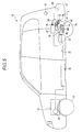
- FIG. 5 shows a vehicle 10 that is an example of the hybrid vehicle.
- the vehicle 10 includes an engine 12 at the front portion, and a rear-wheel electromotor 14 for driving and a fuel tank 22 at the rear portion.
- a driving direction of the vehicle 10 is referred to as the front and the opposite direction to the driving direction is referred to as the rear. Based on this, the right and the left are determined.
- the gravity direction is referred to as the lower and the opposite direction to the gravity direction is referred to as the upper.
- the vehicle 10 includes front wheels 16 at right and left sides of the front portion, and rear wheels 18 at right and left sides of the rear portion.
- the engine 12 is an internal combustion engine that uses gasoline as fuel and is mounted between the front wheels 16.
- the engine 12 includes a transmission, a differential device and the like assembled thereto, which are not shown, and a rotational output of the engine 12 is transmitted to the front wheels 16 through the transmission, the differential device and the like.
- the vehicle 10 includes an ECU (Electronic Control Unit, which is not shown.
- the ECU obtains a variety of information such as operating states of accelerator and brake pedals, which are not shown, vehicle speed and a charged state of a battery 30, which will be described later, and arbitrarily controls the engine 12, the transmission and the like based on the information.
- the engine 12 is not limited to the gasoline engine.
- a generator 20 is provided at a side of the engine 12.
- the generator 20 generates power by rotational forces input from the engine 12 or front wheels 16.
- the battery 30 is provided at a central part in the underfloor space.
- the battery 30 is a battery that drives the vehicle 10 and has a relatively high capacity.
- the power generated in the generator 20 is stored in the battery 30.
- the generator 20 is driven by power from the battery 30 to rotate the front wheels 16 or to start the engine 12.
- the vehicle 10 includes at the rear portion a sub frame 50 including the rear-wheel electromotor 14 assembled thereto.
- FIG. 2 shows the sub frame 50.
- the sub frame 50 has a substantially rectangular shape and includes tubular members 52 and 54, which are main pipes provided at both sides of the vehicle 10, a front cross member 56 provided at the front portions of the tubular members 52 and 54, and a rear cross member 58 (a rear left-right extending member) provided at the rear portions of the tubular members 52 and 54.
- the front cross member 56 is a member having a rectangular section and is provided in a width direction (right-left direction) of the vehicle 10. End portions of the tubular members 52 and 54 are fixed to the front cross member 56 at an interval. In addition, the front cross member 56 is formed with fixing parts 60 at the both end portions thereof. The fixing parts 60 are fixed to a chassis frame 35, which is shown in FIG. 5 , of the vehicle 10.
- the front cross member 56 is provided with a front motor mount bracket 62 at the approximate center thereof.
- the front motor mount bracket 62 has a substantially U shape and extends toward the lower side of the front cross member 56.
- a front motor mount 64 is attached to the inner portion of the front motor mount bracket 62.
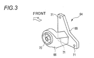
- FIG. 3 shows the front motor mount 64.
- the front motor mount 64 includes a base 66 and an attachment piece 68 that is provided on the base 66.
- the base 66 is formed with a mount part 70 that is attached to the front motor mount bracket 62.
- the attachment piece 68 is a plate member having a substantially triangular shape and has attachment holes 71 formed at three corner portions thereof.
- the tubular members 52 and 54 each of which has a tubular shape are respectively formed into a substantially symmetrical shape with respect to a longitudinal direction (front-rear direction) of the vehicle 10.
- the tubular members 52 and 54 extend rearward from the front cross member 56 with being substantially flush with the front cross member 56 and are bent at the vicinities of the centers thereof so that the tubular members 52 and 54 are opened outwardly.
- Rear end portions of the tubular members 52 and 54 are respectively connected to the right and left end portions of the rear cross member 58.
- Fixing parts 72 are provided at connection portions between the tubular members 52 and 54 and the rear cross member 58.
- the fixing parts 72 are fixed to the chassis frame 35, which is shown in FIG. 5 , of the vehicle 10.
- the rear cross member 58 is a member having a rectangular section, and has both end portions that are bent upwardly. The both end portions of the rear cross member 58 are connected to the tubular members 52 and 54. A central part of the rear cross member 58 is slightly protruded forward. Attachment parts 74 are provided on rear faces of the both end portions of the rear cross member 58. As shown in FIG. 1 , a rear motor mount 76 that is a structure member is fixed to the attachment parts 74 with screws.
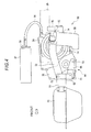
- FIG. 1 shows a state in which the rear-wheel electromotor 14 is assembled inside the sub frame 50.
- the rear-wheel electromotor 14 has a cylindrical shape and is assembled with a direction of an output shaft, which is not shown, thereof being parallel with the width direction of the vehicle 10.
- the rear-wheel electromotor 14 includes a terminal connection part 24 at the upper portion thereof.
- the terminal connection part 24 is a connection port including a predetermined number of connection terminal, which are not shown, and is disposed at the front side of a rear wall of the rear motor mount 76.
- the terminal connection part 24 is connected with one end of a power line 34.
- the power line 34 has a diameter of about 1cm and is thick enough to enable predetermined current to flow therein.
- the other end of the power line 34 is connected to a power control unit 32 that will be described below.
- the power line 34 connected to the terminal connection part 24 is upwardly bent from the terminal connection part 24 and is connected to a connection port 36 of the power control unit 32.
- the connection port 36 is disposed at the front side of the rear wall of the rear motor mount 76, in the same manner as the terminal connection part 24 of the rear-wheel electromotor 14.
- a decelerating differential device 38 is provided at an output shaft section of the rear-wheel electromotor 14.
- the decelerating differential device 38 includes a decelerating gear and a differential gear therein, and right and left rear wheel driving shafts, which are not shown, are connected to an output end portion of the differential gear.
- the rear wheel driving shafts are respectively connected to the rear wheels 18 and transmit rotational output of the rear-wheel electromotor 14 to the right and left rear wheels 18 while performing the differential motion.
- the decelerating differential device 38 may have an accelerating gear therein, rather than the decelerating gear.
- the decelerating differential device 38 includes an attachment hole, which is not shown, at a side face thereof, and the attachment piece 68 of the front motor mount 64 is fixed to the decelerating differential device 38 with a screw 73 through the attachment hole, as shown in FIG. 4 .
- the rear-wheel electromotor 14 is thus attached to the front cross member 56.
- the rear-wheel electromotor 14 is attached in such a way that a center of rotation of the rear-wheel electromotor 14 is substantially flush with the rear cross member 58. Namely, height of the center of the rotation of the rear-wheel electromotor 14 is substantially the same as height of the rear cross member 58.
- the fuel tank 22 is provided at the front side of the front cross member 56.
- the fuel tank 22 is a tank that stores liquid fuel of the engine 12.
- the fuel tank 22 is provided at a position that is below the floor face of the vehicle 10 and is substantially flush with the front cross member 56.
- the rear cross member 58 extends at the lower side of the rear-wheel electromotor 14 at a slight interval with the rear-wheel electromotor 14.
- the rear motor mount 76 extends at the rear side of the rear-wheel electromotor 14 at a slight interval with the rear-wheel electromotor 14.
- the power control unit 32 is provided above the rear-wheel electromotor 14.
- the power control unit 32 is attached to the chassis frame 35 by a stay and the like and controls the charge and discharge of the battery 30 and an operation of the rear-wheel electromotor 14 in response to instructions from the ECU.
- the power control unit 32 includes the connection port 36 and is connected with the power line 34.
- the power control unit 32 is connected to the rear-wheel electromotor 14 through the power line 34.
- the power control unit 32 is also connected to the battery 30 through the power line 34.
- An external power supply connection port 33 is provided at, for example, a rear side face of the vehicle 10.
- the external power supply connection port 33 is a connection port to which an external power supply is connected.
- the battery 30 is charged using the external power supply that is connected to the external power supply connection port 33.
- the vehicle 10 drives in a front-wheel driving manner.
- the driving force of the rear-wheel electromotor 14 is transmitted to the rear wheels 18 through the decelerating differential device 38, and the vehicle 10 drives in a rear-wheel driving manner.
- the driving of the vehicle 10 may drive in the front-wheei driving manner, the rear-wheel driving manner, or an all-wheel driving manner in which all of the front and rear wheels drive at the same time.
- the rear wheels 18 are supported by the suspension provided at the sub frame 50 and arbitrarily operate in the upper and lower directions.
- the impact force due to the rear collision is absorbed while breaking a crushable zone a, which is shown in FIG. 5 , of the rear portion of the vehicle 10 .
- the impact force is within a predetermined range, the vehicle is broken only within the crushable zone a, and the portion of the vehicle which is arranged at the front side of the rear motor mount 76 is little damaged.
- the rear motor mount 76 when the impact force is high and is thus applied to the rear motor mount 76, the rear motor mount 76 is forward deformed. When the impact is absorbed as the rear motor mount 76 is deformed, the rear-wheel electromotor 14 is not damaged.
- the rear cross member 58 is provided below the rear-wheel electromotor 14. Accordingly, even when the front motor mount bracket 62 is broken, the rear-wheel electromotor 14 is put on the rear cross member 58 and is not dropped on the road from the vehicle 10.
- the fuel tank 22 is arranged at the front side of the rear-wheel electromotor 14.
- the invention is not limited to the fuel tank 22 and the other member may be also possible.
- expensive and important parts such as battery, fuel cell and inverter may be arranged at the front side of the rear-wheel electromotor 14.
- the attachment structure of the electromotor of the hybrid vehicle is configured as follows.
- the hybrid vehicle has such a structure that an electromotor is connected to rear wheels of an FF vehicle (Front Engine, Front Drive vehicle).
- the vehicle has a sub frame having a substantially rectangular shape at the rear portion thereof.
- the sub frame is formed into the rectangular shape by arranging members, which extend in a longitudinal direction (front-rear direction), at right and left sides and attaching a front cross member and a rear cross member at front and rear parts of the members, respectively.
- the sub frame may have a suspension assembled at the rear portion of the vehicle and may hold the rear wheels through the suspension so that the rear wheels can move vertically.
- a rear motor mount which is a structure member, is attached to the rear side of the sub frame.
- the electromotor is attached at an inside of the sub frame, i.e., a space surrounded by the above described members which arranged at the right and left sides and which extend in the front-rear direction, the front cross member, the rear cross member and the rear motor mount.
- the electromotor is attached as follows.
- a bracket which is a front motor mount bracket, to which a connection member, which is a front motor mount, is attached, is provided at the front cross member.
- the front motor mount includes a mount part at the front portion thereof and an attachment part at the rear portion thereof which is integrally formed with the mount part.
- the mount part of the front motor mount is attached to the bracket, and the attachment part is attached to the electromotor.
- the electromotor is fixed to the sub frame.
- the rear cross member is disposed below the electromotor at a slight interval with the electromotor.
- the rear motor mount is provided at the rear side of the electromotor at a slight interval with the electromotor. Both end portions of the rear motor mount are attached to right and left end portions of the rear cross member.
- the electromotor is attached to the sub frame at a position that is slightly higher than a center of the mount part of the front motor mount.
- a fuel tank is disposed at the front side of the front cross member at a position that is substantially the same in height as a position of the front cross member, at a slight interval with the front cross member.
- the attachment structure of the electromotor of the invention has following effects. Since the electromotor is provided adjacent to the rear wheels, it is possible to drive the vehicle while effectively driving the rear wheels. When the vehicle is collided from the rear side, the rear motor mount receives the impact by the rear collision. Since there is a gap between the rear motor mount and the electromotor, the electromotor is not damaged.
- the electromotor moves without contacting the fuel tank. Accordingly, it is possible to prevent the fuel tank from being damaged due to the electromotor, In addition, even when the front motor mount is damaged, the electromotor is put on the rear cross member and is prevented from being completely detached from the vehicle.
- the present invention can be applied to an electric vehicle or hybrid vehicle having an electromotor connected to rear wheels.
Abstract
Description
- The invention relates to an attachment structure of an electromotor connected to rear wheels of a hybrid vehicle.
- There is a hybrid vehicle based on an FF vehicle (Front Engine, Front Drive vehicle) in which an electromotor is connected to rear wheels thereof and driving is enabled by an engine and the electromotor. In the FF vehicle, there is a structure in which a fuel tank is disposed below a rear seat to secure a wide interior space or accommodating space. In the meantime, regarding an example in which the electromotor is connected to the rear wheels, there is a structure in which an electromotor is provided adjacent to rear wheels to simplify the structure and to improve transmission efficiency (for example, see
JP-A-11-165516 - Due to this, for a hybrid vehicle based on the FF vehicle in which the electromotor is connected to the rear wheels, a structure is considered in which a fuel tank is arranged just before the electromotor.
- However, according to the hybrid vehicle having the above structure, when the vehicle is collided from the rear (hereinafter, referred to as rear collision), the electromotor may be forward pushed by the rear collision, thereby damaging the fuel tank.
- It is therefore an object of the invention to provide an attachment structure of an electromotor capable of preventing a fuel tank from being damaged even when the electromotor is pushed out at the time of rear collision in a vehicle having an electromotor arranged at a rear portion of the vehicle.
- In order to achieve the object, according to the invention, there is provided an attachment structure of an electromotor of a vehicle, the electromotor which is connected to rear wheels, the attachment structure comprising: a sub frame provided at a rear portion of the hybrid vehicle, and including at least two first members which extend in a first direction that is a longitudinal direction of the vehicle and at least two second members which extend in a second direction that is a width direction of the vehicle and which include a front member and a rear member, the sub frame having a substantially rectangular shape in a third direction perpendicular to the first direction and the second direction, the sub frame to which the electromotor is assembled, a receptacle being provided at a front side of the sub frame; a rear motor mount provided at a rear side of the rear member, a position of the rear motor mount being substantially the same as a position of the electromotor in the third direction, the electromotor being provided at an upper side of the rear member; and a connection member provided at a lower side of the front member, the connection member to which the electromotor is fixed.
- The vehicle may include an internal combustion engine, and the receptacle may be a fuel tank that stores liquid fuel of the internal combustion engine.
- The connection member may include a mount part and an attachment part that is connected to the mount part, the front member may include a bracket at a lower side thereof, the mount part may be attached to the bracket, and the attachment part may be attached to the electromotor.
-
-
FIG. 1 is a perspective view showing an assembly structure of an electromotor according to an illustrative embodiment of the invention. -
FIG. 2 is a perspective view showing an illustrative embodiment of a sub frame. -
FIG. 3 is a perspective view showing an illustrative embodiment of a front motor mount. -
FIG. 4 is a side view showing the assembly structure of the electromotor according to an illustrative embodiment shown inFIG. 1 . -
FIG. 5 is a structural view showing an illustrative embodiment of a vehicle having assembled a rear-wheel electromotor thereto. - An illustrative embodiment of an attachment structure of an electromotor in a hybrid vehicle of the invention will be described.
-
FIG. 5 shows avehicle 10 that is an example of the hybrid vehicle. Thevehicle 10 includes anengine 12 at the front portion, and a rear-wheel electromotor 14 for driving and afuel tank 22 at the rear portion. Hereinafter, a driving direction of thevehicle 10 is referred to as the front and the opposite direction to the driving direction is referred to as the rear. Based on this, the right and the left are determined. In addition, the gravity direction is referred to as the lower and the opposite direction to the gravity direction is referred to as the upper. - The
vehicle 10 includesfront wheels 16 at right and left sides of the front portion, andrear wheels 18 at right and left sides of the rear portion. Theengine 12 is an internal combustion engine that uses gasoline as fuel and is mounted between thefront wheels 16. Theengine 12 includes a transmission, a differential device and the like assembled thereto, which are not shown, and a rotational output of theengine 12 is transmitted to thefront wheels 16 through the transmission, the differential device and the like. - The
vehicle 10 includes an ECU (Electronic Control Unit, which is not shown. The ECU obtains a variety of information such as operating states of accelerator and brake pedals, which are not shown, vehicle speed and a charged state of abattery 30, which will be described later, and arbitrarily controls theengine 12, the transmission and the like based on the information. In the meantime, it should be noted that theengine 12 is not limited to the gasoline engine. - A
generator 20 is provided at a side of theengine 12. Thegenerator 20 generates power by rotational forces input from theengine 12 orfront wheels 16. Thebattery 30 is provided at a central part in the underfloor space. Thebattery 30 is a battery that drives thevehicle 10 and has a relatively high capacity. The power generated in thegenerator 20 is stored in thebattery 30. In the meantime, it may be possible that thegenerator 20 is driven by power from thebattery 30 to rotate thefront wheels 16 or to start theengine 12. Thevehicle 10 includes at the rear portion asub frame 50 including the rear-wheel electromotor 14 assembled thereto. - Next, the
sub frame 50 will be described. -
FIG. 2 shows thesub frame 50. As shown inFIG. 2 , thesub frame 50 has a substantially rectangular shape and includestubular members vehicle 10, afront cross member 56 provided at the front portions of thetubular members tubular members - The
front cross member 56 is a member having a rectangular section and is provided in a width direction (right-left direction) of thevehicle 10. End portions of thetubular members front cross member 56 at an interval. In addition, thefront cross member 56 is formed withfixing parts 60 at the both end portions thereof. Thefixing parts 60 are fixed to achassis frame 35, which is shown inFIG. 5 , of thevehicle 10. - Further, the
front cross member 56 is provided with a frontmotor mount bracket 62 at the approximate center thereof. The frontmotor mount bracket 62 has a substantially U shape and extends toward the lower side of thefront cross member 56. Afront motor mount 64 is attached to the inner portion of the frontmotor mount bracket 62. -
FIG. 3 shows thefront motor mount 64. As shown inFIG. 3 , thefront motor mount 64 includes abase 66 and anattachment piece 68 that is provided on thebase 66. Thebase 66 is formed with amount part 70 that is attached to the frontmotor mount bracket 62. Theattachment piece 68 is a plate member having a substantially triangular shape and hasattachment holes 71 formed at three corner portions thereof. - The
tubular members vehicle 10. Thetubular members front cross member 56 with being substantially flush with thefront cross member 56 and are bent at the vicinities of the centers thereof so that thetubular members tubular members rear cross member 58. -
Fixing parts 72 are provided at connection portions between thetubular members rear cross member 58. Thefixing parts 72 are fixed to thechassis frame 35, which is shown inFIG. 5 , of thevehicle 10. - The
rear cross member 58 is a member having a rectangular section, and has both end portions that are bent upwardly. The both end portions of therear cross member 58 are connected to thetubular members rear cross member 58 is slightly protruded forward.Attachment parts 74 are provided on rear faces of the both end portions of therear cross member 58. As shown inFIG. 1 , arear motor mount 76 that is a structure member is fixed to theattachment parts 74 with screws. -
FIG. 1 shows a state in which the rear-wheel electromotor 14 is assembled inside thesub frame 50. The rear-wheel electromotor 14 has a cylindrical shape and is assembled with a direction of an output shaft, which is not shown, thereof being parallel with the width direction of thevehicle 10. - The rear-
wheel electromotor 14 includes aterminal connection part 24 at the upper portion thereof. Theterminal connection part 24 is a connection port including a predetermined number of connection terminal, which are not shown, and is disposed at the front side of a rear wall of therear motor mount 76. Theterminal connection part 24 is connected with one end of apower line 34. Thepower line 34 has a diameter of about 1cm and is thick enough to enable predetermined current to flow therein. The other end of thepower line 34 is connected to apower control unit 32 that will be described below. Thepower line 34 connected to theterminal connection part 24 is upwardly bent from theterminal connection part 24 and is connected to aconnection port 36 of thepower control unit 32. Theconnection port 36 is disposed at the front side of the rear wall of therear motor mount 76, in the same manner as theterminal connection part 24 of the rear-wheel electromotor 14. - A decelerating
differential device 38 is provided at an output shaft section of the rear-wheel electromotor 14. The deceleratingdifferential device 38 includes a decelerating gear and a differential gear therein, and right and left rear wheel driving shafts, which are not shown, are connected to an output end portion of the differential gear. The rear wheel driving shafts are respectively connected to therear wheels 18 and transmit rotational output of the rear-wheel electromotor 14 to the right and leftrear wheels 18 while performing the differential motion. In the meantime, the deceleratingdifferential device 38 may have an accelerating gear therein, rather than the decelerating gear. - The decelerating
differential device 38 includes an attachment hole, which is not shown, at a side face thereof, and theattachment piece 68 of thefront motor mount 64 is fixed to the deceleratingdifferential device 38 with ascrew 73 through the attachment hole, as shown inFIG. 4 . The rear-wheel electromotor 14 is thus attached to thefront cross member 56. - The rear-
wheel electromotor 14 is attached in such a way that a center of rotation of the rear-wheel electromotor 14 is substantially flush with therear cross member 58. Namely, height of the center of the rotation of the rear-wheel electromotor 14 is substantially the same as height of therear cross member 58. Thefuel tank 22 is provided at the front side of thefront cross member 56. Thefuel tank 22 is a tank that stores liquid fuel of theengine 12. Thefuel tank 22 is provided at a position that is below the floor face of thevehicle 10 and is substantially flush with thefront cross member 56. - The
rear cross member 58 extends at the lower side of the rear-wheel electromotor 14 at a slight interval with the rear-wheel electromotor 14. In addition, therear motor mount 76 extends at the rear side of the rear-wheel electromotor 14 at a slight interval with the rear-wheel electromotor 14. - The
power control unit 32 is provided above the rear-wheel electromotor 14. Thepower control unit 32 is attached to thechassis frame 35 by a stay and the like and controls the charge and discharge of thebattery 30 and an operation of the rear-wheel electromotor 14 in response to instructions from the ECU. - The
power control unit 32 includes theconnection port 36 and is connected with thepower line 34. Thepower control unit 32 is connected to the rear-wheel electromotor 14 through thepower line 34. Thepower control unit 32 is also connected to thebattery 30 through thepower line 34. - An external power
supply connection port 33 is provided at, for example, a rear side face of thevehicle 10. The external powersupply connection port 33 is a connection port to which an external power supply is connected. Thebattery 30 is charged using the external power supply that is connected to the external powersupply connection port 33. - Next, operational effects of the attachment structure of the electromotor of the hybrid vehicle will be described.
- When the
engine 12 is operated and power is thus transmitted to thefront wheels 16, thevehicle 10 drives in a front-wheel driving manner. In addition, when the power is supplied to the rear-wheel electromotor 14 from thepower control unit 32, the driving force of the rear-wheel electromotor 14 is transmitted to therear wheels 18 through the deceleratingdifferential device 38, and thevehicle 10 drives in a rear-wheel driving manner. The driving of thevehicle 10 may drive in the front-wheei driving manner, the rear-wheel driving manner, or an all-wheel driving manner in which all of the front and rear wheels drive at the same time. Therear wheels 18 are supported by the suspension provided at thesub frame 50 and arbitrarily operate in the upper and lower directions. - When the
vehicle 10 is collided from the rear side, the impact force due to the rear collision is absorbed while breaking a crushable zone a, which is shown inFIG. 5 , of the rear portion of thevehicle 10 . when the impact force is within a predetermined range, the vehicle is broken only within the crushable zone a, and the portion of the vehicle which is arranged at the front side of therear motor mount 76 is little damaged. - However, when the impact force is high and is thus applied to the
rear motor mount 76, therear motor mount 76 is forward deformed. When the impact is absorbed as therear motor mount 76 is deformed, the rear-wheel electromotor 14 is not damaged. - When the impact is higher and thus the
rear motor mount 76 is highly displaced forward while deforming thesub frame 50, therear motor mount 76 pushes the rear-wheel electromotor 14. Hence, the frontmotor mount bracket 62 is damaged and the rear-wheel electromotor 14 is forward moved. However, the rear-wheel electromotor 14 is hindered from moving forward while contacting thefront cross member 56 and is moved obliquely downward so that the rear-wheel electromotor 14 moves below thefront cross member 56. - Thereby, even when the high impact is appl ied, the rear-
wheel electromotor 14 is moved obliquely downward. Thus, the damage of thefuel tank 22 due to the contact of the rear-wheel electromotor. 14 is not caused. - In addition, the
rear cross member 58 is provided below the rear-wheel electromotor 14. Accordingly, even when the frontmotor mount bracket 62 is broken, the rear-wheel electromotor 14 is put on therear cross member 58 and is not dropped on the road from thevehicle 10. - In the above exemplary embodiment, the
fuel tank 22 is arranged at the front side of the rear-wheel electromotor 14. However, the invention is not limited to thefuel tank 22 and the other member may be also possible. For example, expensive and important parts such as battery, fuel cell and inverter may be arranged at the front side of the rear-wheel electromotor 14. - According to an aspect of the invention, the attachment structure of the electromotor of the hybrid vehicle is configured as follows.
- The hybrid vehicle has such a structure that an electromotor is connected to rear wheels of an FF vehicle (Front Engine, Front Drive vehicle). The vehicle has a sub frame having a substantially rectangular shape at the rear portion thereof. For example, the sub frame is formed into the rectangular shape by arranging members, which extend in a longitudinal direction (front-rear direction), at right and left sides and attaching a front cross member and a rear cross member at front and rear parts of the members, respectively. The sub frame may have a suspension assembled at the rear portion of the vehicle and may hold the rear wheels through the suspension so that the rear wheels can move vertically. In addition, a rear motor mount, which is a structure member, is attached to the rear side of the sub frame.
- The electromotor is attached at an inside of the sub frame, i.e., a space surrounded by the above described members which arranged at the right and left sides and which extend in the front-rear direction, the front cross member, the rear cross member and the rear motor mount.
- To be more specific, the electromotor is attached as follows. A bracket, which is a front motor mount bracket, to which a connection member, which is a front motor mount, is attached, is provided at the front cross member. The front motor mount includes a mount part at the front portion thereof and an attachment part at the rear portion thereof which is integrally formed with the mount part. The mount part of the front motor mount is attached to the bracket, and the attachment part is attached to the electromotor. Thereby, the electromotor is fixed to the sub frame.
- In addition, the rear cross member is disposed below the electromotor at a slight interval with the electromotor. The rear motor mount is provided at the rear side of the electromotor at a slight interval with the electromotor. Both end portions of the rear motor mount are attached to right and left end portions of the rear cross member. Furthermore, the electromotor is attached to the sub frame at a position that is slightly higher than a center of the mount part of the front motor mount. A fuel tank is disposed at the front side of the front cross member at a position that is substantially the same in height as a position of the front cross member, at a slight interval with the front cross member.
- The attachment structure of the electromotor of the invention has following effects. Since the electromotor is provided adjacent to the rear wheels, it is possible to drive the vehicle while effectively driving the rear wheels. When the vehicle is collided from the rear side, the rear motor mount receives the impact by the rear collision. Since there is a gap between the rear motor mount and the electromotor, the electromotor is not damaged.
- When the energy of the rear collision is high and thus the rear motor mount or rear cross member is deformed, the electromotor is pushed forward and the front cross mount is thus damaged. However, the electromotor is hindered from moving by the front cross member provided at the front side of the electromotor, so that the electromotor is pushed out obliquely downward.
- Thereby, even when the electromotor is pushed from the rear side, the electromotor moves without contacting the fuel tank. Accordingly, it is possible to prevent the fuel tank from being damaged due to the electromotor, In addition, even when the front motor mount is damaged, the electromotor is put on the rear cross member and is prevented from being completely detached from the vehicle.
- The present invention can be applied to an electric vehicle or hybrid vehicle having an electromotor connected to rear wheels.
Claims (3)
- An attachment structure of an electromotor of a vehicle, the electromotor which is connected to rear wheels, the attachment structure comprising:a sub frame provided at a rear portion of the hybrid vehicle, and including at least two first members which extend in a first direction that is a longitudinal direction of the vehicle and at least two second members which extend in a second direction that is a width direction of the vehicle and which include a front member and a rear member, the sub frame having a substantially rectangular shape in a third direction perpendicular to the first direction and the second direction, the sub frame to which the electromotor is assembled, a receptacle being provided at a front side of the sub frame;a rear motor mount provided at a rear side of the rear member, a position of the rear motor mount being substantially the same as a position of the electromotor in the third direction, the electromotor being provided at an upper side of the rear member; anda connection member provided at a lower side of the front member, the connection member to which the electromotor is fixed.
- The attachment structure according to claim 1, wherein the vehicle includes an internal combustion engine, and the receptacle is a fuel tank that stores liquid fuel of the internal combustion engine.
- The attachment structure according to claim 1 or claim 2, wherein
the connection member includes a mount part and an attachment part that is connected to the mount part,
the front member includes a bracket at a lower side thereof,
the mount part is attached to the bracket, and
the attachment part is attached to the electromotor.
Applications Claiming Priority (1)
| Application Number | Priority Date | Filing Date | Title |
|---|---|---|---|
| JP2009275770A JP5115543B2 (en) | 2009-12-03 | 2009-12-03 | Installation structure of electric motor for hybrid vehicle |
Publications (3)
| Publication Number | Publication Date |
|---|---|
| EP2329980A2 true EP2329980A2 (en) | 2011-06-08 |
| EP2329980A3 EP2329980A3 (en) | 2013-11-27 |
| EP2329980B1 EP2329980B1 (en) | 2015-02-11 |
Family
ID=43795087
Family Applications (1)
| Application Number | Title | Priority Date | Filing Date |
|---|---|---|---|
| EP10193665.6A Active EP2329980B1 (en) | 2009-12-03 | 2010-12-03 | Attachment structure of electromotor of hybrid vehicle |
Country Status (4)
| Country | Link |
|---|---|
| US (1) | US8522909B2 (en) |
| EP (1) | EP2329980B1 (en) |
| JP (1) | JP5115543B2 (en) |
| CN (1) | CN102085797B (en) |
Cited By (2)
| Publication number | Priority date | Publication date | Assignee | Title |
|---|---|---|---|---|
| FR3019131A1 (en) * | 2014-03-31 | 2015-10-02 | Peugeot Citroen Automobiles Sa | VEHICLE CHASSIS SUPPORTING A VEHICLE TRACTION ELECTRIC MOTOR POWERTRAIN |
| EP3202606A1 (en) * | 2016-02-04 | 2017-08-09 | Honda Motor Co., Ltd. | Four wheel vehicle |
Families Citing this family (24)
| Publication number | Priority date | Publication date | Assignee | Title |
|---|---|---|---|---|
| US9394004B2 (en) * | 2010-11-02 | 2016-07-19 | Honda Motor Co., Ltd. | Electric automobile |
| JP5790365B2 (en) * | 2011-09-20 | 2015-10-07 | トヨタ自動車株式会社 | Vehicle battery mounting structure |
| US20130181485A1 (en) * | 2011-10-21 | 2013-07-18 | Fisker Automotive, Inc. | Rear-wheel drive, plug-in hybrid electric vehicle modular subframe assembly and method |
| US8917000B2 (en) * | 2011-11-24 | 2014-12-23 | Honda Motor Co., Ltd. | Arrangement structure of connecting conductor connecting inside and outside conductors of motor |
| JP5929435B2 (en) * | 2012-04-04 | 2016-06-08 | スズキ株式会社 | Hybrid vehicle power unit |
| WO2014097514A1 (en) * | 2012-12-21 | 2014-06-26 | 本田技研工業株式会社 | Motor mounting structure |
| JP6011320B2 (en) * | 2012-12-25 | 2016-10-19 | スズキ株式会社 | Vehicle rear structure |
| US9126581B2 (en) * | 2013-05-08 | 2015-09-08 | GM Global Technology Operations LLC | Hybrid powertrain and modular rear drive unit for same |
| DE102013106141A1 (en) * | 2013-06-13 | 2014-12-18 | Dr. Ing. H.C. F. Porsche Aktiengesellschaft | Bearing frame for an electrically driven motor vehicle |
| CN103381836B (en) * | 2013-07-11 | 2015-11-25 | 唐山轨道客车有限责任公司 | Dynamic assembly erecting frame, package system, assemble method and diesel coach set |
| JP6071848B2 (en) * | 2013-11-07 | 2017-02-01 | 本田技研工業株式会社 | Electric vehicle |
| JP5938532B2 (en) * | 2013-12-02 | 2016-06-22 | 本田技研工業株式会社 | vehicle |
| US9573452B2 (en) * | 2014-04-07 | 2017-02-21 | Squaw-Fleet, LLC | Rear carriage structure for an electric vehicle |
| DE102015013168A1 (en) | 2015-10-09 | 2017-04-13 | Audi Ag | Subframe for a vehicle axle |
| US9874264B2 (en) * | 2015-11-18 | 2018-01-23 | Toyota Motor Engineering & Manufacturing North America, Inc. | Magnetic field activated powertrain mount |
| JP6493183B2 (en) * | 2015-12-04 | 2019-04-03 | トヨタ自動車株式会社 | Vehicle structure |
| DE102015224894A1 (en) * | 2015-12-10 | 2017-06-14 | Volkswagen Aktiengesellschaft | Hinterachshilfsrahmen and motor vehicle with such a Hinterachshilfsrahmen |
| WO2017215171A1 (en) * | 2016-06-14 | 2017-12-21 | 北京新能源汽车股份有限公司 | Connection structure between rear cross member and motor bracket of vehicle and vehicle |
| US10202028B1 (en) * | 2017-08-09 | 2019-02-12 | Ford Global Technologies, Llc | Vehicle Traction Battery Sub-Frame Assembly |
| JP6692381B2 (en) * | 2018-03-13 | 2020-05-13 | 本田技研工業株式会社 | Power unit structure of electric vehicle |
| JP6778725B2 (en) * | 2018-09-12 | 2020-11-04 | 本田技研工業株式会社 | vehicle |
| JP6871971B2 (en) * | 2019-05-28 | 2021-05-19 | 本田技研工業株式会社 | vehicle |
| KR102644582B1 (en) * | 2019-10-15 | 2024-03-06 | 현대자동차주식회사 | Mounting system for powertrain of vehicle |
| JP7375665B2 (en) | 2020-04-20 | 2023-11-08 | 日産自動車株式会社 | car body structure |
Citations (1)
| Publication number | Priority date | Publication date | Assignee | Title |
|---|---|---|---|---|
| JPH11165516A (en) | 1985-06-27 | 1999-06-22 | Suzuki Motor Corp | Rear axle mounting structure of electric vehicle |
Family Cites Families (7)
| Publication number | Priority date | Publication date | Assignee | Title |
|---|---|---|---|---|
| US5366151A (en) * | 1993-12-27 | 1994-11-22 | Ford Motor Company | Hybrid vehicle fuel vapor management apparatus |
| US5405167A (en) * | 1994-01-21 | 1995-04-11 | Hyundai Motor Company | Combined subframe and fuel tank for use in automobiles |
| JP4241292B2 (en) * | 2003-09-26 | 2009-03-18 | マツダ株式会社 | Rear wheel drive mounting structure |
| US7588117B2 (en) * | 2003-09-29 | 2009-09-15 | Nissan Motor Co., Ltd. | Structure and method for mounting drive motor |
| JP4825583B2 (en) * | 2005-06-28 | 2011-11-30 | 本田技研工業株式会社 | Body structure |
| JP4345795B2 (en) * | 2006-09-28 | 2009-10-14 | 三菱自動車工業株式会社 | Vehicle motor mount structure |
| EP2184219B1 (en) * | 2007-09-06 | 2013-02-20 | Mitsubishi Jidosha Kogyo Kabushiki Kaisha | Electric automobile |
-
2009
- 2009-12-03 JP JP2009275770A patent/JP5115543B2/en active Active
-
2010
- 2010-12-02 US US12/959,076 patent/US8522909B2/en active Active
- 2010-12-03 CN CN201010585073.3A patent/CN102085797B/en active Active
- 2010-12-03 EP EP10193665.6A patent/EP2329980B1/en active Active
Patent Citations (1)
| Publication number | Priority date | Publication date | Assignee | Title |
|---|---|---|---|---|
| JPH11165516A (en) | 1985-06-27 | 1999-06-22 | Suzuki Motor Corp | Rear axle mounting structure of electric vehicle |
Cited By (3)
| Publication number | Priority date | Publication date | Assignee | Title |
|---|---|---|---|---|
| FR3019131A1 (en) * | 2014-03-31 | 2015-10-02 | Peugeot Citroen Automobiles Sa | VEHICLE CHASSIS SUPPORTING A VEHICLE TRACTION ELECTRIC MOTOR POWERTRAIN |
| EP3202606A1 (en) * | 2016-02-04 | 2017-08-09 | Honda Motor Co., Ltd. | Four wheel vehicle |
| US10053153B2 (en) | 2016-02-04 | 2018-08-21 | Honda Motor Co., Ltd. | Four wheel vehicle |
Also Published As
| Publication number | Publication date |
|---|---|
| EP2329980A3 (en) | 2013-11-27 |
| JP5115543B2 (en) | 2013-01-09 |
| CN102085797A (en) | 2011-06-08 |
| EP2329980B1 (en) | 2015-02-11 |
| US20110132672A1 (en) | 2011-06-09 |
| US8522909B2 (en) | 2013-09-03 |
| JP2011116251A (en) | 2011-06-16 |
| CN102085797B (en) | 2014-06-18 |
Similar Documents
| Publication | Publication Date | Title |
|---|---|---|
| EP2329980B1 (en) | Attachment structure of electromotor of hybrid vehicle | |
| EP3753771B1 (en) | Vehicle drive device | |
| JP5494499B2 (en) | Electric vehicle | |
| EP3023281B1 (en) | Hybrid vehicle | |
| EP3789273A1 (en) | Vehicle front structure and vehicle | |
| JP2005247063A (en) | Storage mechanism mounting structure | |
| US10752072B2 (en) | Electrified vehicle with vibration isolator within frame and corresponding method | |
| JP5338642B2 (en) | Motor mounting structure | |
| JP5589766B2 (en) | Parts mounting structure in the motor room of electric vehicles | |
| CN114056075A (en) | System and method for electric heavy vehicle | |
| CN108215748A (en) | Electric vehicle | |
| EP2440419A1 (en) | Vehicle body structure | |
| JP5468163B2 (en) | Device for fixing the battery module to the body shell of an automobile | |
| CN110920372A (en) | High voltage battery support and isolation for an electric vehicle | |
| US10622607B2 (en) | Electrified vehicle battery packs designed with sacrificial components | |
| US11173777B2 (en) | Battery pack mounting system and mounting method | |
| JP2024007745A (en) | Fuel cell vehicle | |
| JP5929749B2 (en) | On-board equipment mounting structure | |
| JP7421333B2 (en) | car body structure | |
| JP7461738B2 (en) | vehicle | |
| CN110816243A (en) | Mounting solution for an electric vehicle battery | |
| CN212667096U (en) | Vehicle with a steering wheel | |
| KR102656670B1 (en) | Electric Vehicle Platform with In-Wheel Motor | |
| JP2013193652A (en) | Electric vehicle | |
| JP2021133837A (en) | Vehicle body structure |
Legal Events
| Date | Code | Title | Description |
|---|---|---|---|
| PUAI | Public reference made under article 153(3) epc to a published international application that has entered the european phase |
Free format text: ORIGINAL CODE: 0009012 |
|
| AK | Designated contracting states |
Kind code of ref document: A2 Designated state(s): AL AT BE BG CH CY CZ DE DK EE ES FI FR GB GR HR HU IE IS IT LI LT LU LV MC MK MT NL NO PL PT RO RS SE SI SK SM TR |
|
| AX | Request for extension of the european patent |
Extension state: BA ME |
|
| RIN1 | Information on inventor provided before grant (corrected) |
Inventor name: NIINA, YUZO |
|
| PUAL | Search report despatched |
Free format text: ORIGINAL CODE: 0009013 |
|
| AK | Designated contracting states |
Kind code of ref document: A3 Designated state(s): AL AT BE BG CH CY CZ DE DK EE ES FI FR GB GR HR HU IE IS IT LI LT LU LV MC MK MT NL NO PL PT RO RS SE SI SK SM TR |
|
| AX | Request for extension of the european patent |
Extension state: BA ME |
|
| RIC1 | Information provided on ipc code assigned before grant |
Ipc: B60K 17/356 20060101ALI20131022BHEP Ipc: B60K 1/04 20060101ALI20131022BHEP Ipc: B62D 21/11 20060101ALI20131022BHEP Ipc: B60K 15/063 20060101ALI20131022BHEP Ipc: B60K 1/00 20060101AFI20131022BHEP |
|
| 17P | Request for examination filed |
Effective date: 20140527 |
|
| GRAP | Despatch of communication of intention to grant a patent |
Free format text: ORIGINAL CODE: EPIDOSNIGR1 |
|
| RBV | Designated contracting states (corrected) |
Designated state(s): AL AT BE BG CH CY CZ DE DK EE ES FI FR GB GR HR HU IE IS IT LI LT LU LV MC MK MT NL NO PL PT RO RS SE SI SK SM TR |
|
| INTG | Intention to grant announced |
Effective date: 20140710 |
|
| GRAS | Grant fee paid |
Free format text: ORIGINAL CODE: EPIDOSNIGR3 |
|
| GRAA | (expected) grant |
Free format text: ORIGINAL CODE: 0009210 |
|
| AK | Designated contracting states |
Kind code of ref document: B1 Designated state(s): AL AT BE BG CH CY CZ DE DK EE ES FI FR GB GR HR HU IE IS IT LI LT LU LV MC MK MT NL NO PL PT RO RS SE SI SK SM TR |
|
| REG | Reference to a national code |
Ref country code: GB Ref legal event code: FG4D |
|
| REG | Reference to a national code |
Ref country code: CH Ref legal event code: EP |
|
| REG | Reference to a national code |
Ref country code: IE Ref legal event code: FG4D |
|
| REG | Reference to a national code |
Ref country code: AT Ref legal event code: REF Ref document number: 709801 Country of ref document: AT Kind code of ref document: T Effective date: 20150315 |
|
| REG | Reference to a national code |
Ref country code: DE Ref legal event code: R096 Ref document number: 602010022184 Country of ref document: DE Effective date: 20150326 |
|
| REG | Reference to a national code |
Ref country code: NL Ref legal event code: VDEP Effective date: 20150211 |
|
| REG | Reference to a national code |
Ref country code: AT Ref legal event code: MK05 Ref document number: 709801 Country of ref document: AT Kind code of ref document: T Effective date: 20150211 |
|
| REG | Reference to a national code |
Ref country code: LT Ref legal event code: MG4D |
|
| PG25 | Lapsed in a contracting state [announced via postgrant information from national office to epo] |
Ref country code: SE Free format text: LAPSE BECAUSE OF FAILURE TO SUBMIT A TRANSLATION OF THE DESCRIPTION OR TO PAY THE FEE WITHIN THE PRESCRIBED TIME-LIMIT Effective date: 20150211 Ref country code: LT Free format text: LAPSE BECAUSE OF FAILURE TO SUBMIT A TRANSLATION OF THE DESCRIPTION OR TO PAY THE FEE WITHIN THE PRESCRIBED TIME-LIMIT Effective date: 20150211 Ref country code: NO Free format text: LAPSE BECAUSE OF FAILURE TO SUBMIT A TRANSLATION OF THE DESCRIPTION OR TO PAY THE FEE WITHIN THE PRESCRIBED TIME-LIMIT Effective date: 20150511 Ref country code: FI Free format text: LAPSE BECAUSE OF FAILURE TO SUBMIT A TRANSLATION OF THE DESCRIPTION OR TO PAY THE FEE WITHIN THE PRESCRIBED TIME-LIMIT Effective date: 20150211 Ref country code: ES Free format text: LAPSE BECAUSE OF FAILURE TO SUBMIT A TRANSLATION OF THE DESCRIPTION OR TO PAY THE FEE WITHIN THE PRESCRIBED TIME-LIMIT Effective date: 20150211 Ref country code: HR Free format text: LAPSE BECAUSE OF FAILURE TO SUBMIT A TRANSLATION OF THE DESCRIPTION OR TO PAY THE FEE WITHIN THE PRESCRIBED TIME-LIMIT Effective date: 20150211 |
|
| PG25 | Lapsed in a contracting state [announced via postgrant information from national office to epo] |
Ref country code: LV Free format text: LAPSE BECAUSE OF FAILURE TO SUBMIT A TRANSLATION OF THE DESCRIPTION OR TO PAY THE FEE WITHIN THE PRESCRIBED TIME-LIMIT Effective date: 20150211 Ref country code: AT Free format text: LAPSE BECAUSE OF FAILURE TO SUBMIT A TRANSLATION OF THE DESCRIPTION OR TO PAY THE FEE WITHIN THE PRESCRIBED TIME-LIMIT Effective date: 20150211 Ref country code: RS Free format text: LAPSE BECAUSE OF FAILURE TO SUBMIT A TRANSLATION OF THE DESCRIPTION OR TO PAY THE FEE WITHIN THE PRESCRIBED TIME-LIMIT Effective date: 20150211 Ref country code: NL Free format text: LAPSE BECAUSE OF FAILURE TO SUBMIT A TRANSLATION OF THE DESCRIPTION OR TO PAY THE FEE WITHIN THE PRESCRIBED TIME-LIMIT Effective date: 20150211 Ref country code: GR Free format text: LAPSE BECAUSE OF FAILURE TO SUBMIT A TRANSLATION OF THE DESCRIPTION OR TO PAY THE FEE WITHIN THE PRESCRIBED TIME-LIMIT Effective date: 20150512 Ref country code: IS Free format text: LAPSE BECAUSE OF FAILURE TO SUBMIT A TRANSLATION OF THE DESCRIPTION OR TO PAY THE FEE WITHIN THE PRESCRIBED TIME-LIMIT Effective date: 20150611 |
|
| PG25 | Lapsed in a contracting state [announced via postgrant information from national office to epo] |
Ref country code: EE Free format text: LAPSE BECAUSE OF FAILURE TO SUBMIT A TRANSLATION OF THE DESCRIPTION OR TO PAY THE FEE WITHIN THE PRESCRIBED TIME-LIMIT Effective date: 20150211 Ref country code: RO Free format text: LAPSE BECAUSE OF FAILURE TO SUBMIT A TRANSLATION OF THE DESCRIPTION OR TO PAY THE FEE WITHIN THE PRESCRIBED TIME-LIMIT Effective date: 20150211 Ref country code: SK Free format text: LAPSE BECAUSE OF FAILURE TO SUBMIT A TRANSLATION OF THE DESCRIPTION OR TO PAY THE FEE WITHIN THE PRESCRIBED TIME-LIMIT Effective date: 20150211 Ref country code: DK Free format text: LAPSE BECAUSE OF FAILURE TO SUBMIT A TRANSLATION OF THE DESCRIPTION OR TO PAY THE FEE WITHIN THE PRESCRIBED TIME-LIMIT Effective date: 20150211 Ref country code: CZ Free format text: LAPSE BECAUSE OF FAILURE TO SUBMIT A TRANSLATION OF THE DESCRIPTION OR TO PAY THE FEE WITHIN THE PRESCRIBED TIME-LIMIT Effective date: 20150211 |
|
| REG | Reference to a national code |
Ref country code: FR Ref legal event code: PLFP Year of fee payment: 6 |
|
| REG | Reference to a national code |
Ref country code: DE Ref legal event code: R097 Ref document number: 602010022184 Country of ref document: DE |
|
| PG25 | Lapsed in a contracting state [announced via postgrant information from national office to epo] |
Ref country code: PL Free format text: LAPSE BECAUSE OF FAILURE TO SUBMIT A TRANSLATION OF THE DESCRIPTION OR TO PAY THE FEE WITHIN THE PRESCRIBED TIME-LIMIT Effective date: 20150211 |
|
| PLBE | No opposition filed within time limit |
Free format text: ORIGINAL CODE: 0009261 |
|
| STAA | Information on the status of an ep patent application or granted ep patent |
Free format text: STATUS: NO OPPOSITION FILED WITHIN TIME LIMIT |
|
| PG25 | Lapsed in a contracting state [announced via postgrant information from national office to epo] |
Ref country code: IT Free format text: LAPSE BECAUSE OF FAILURE TO SUBMIT A TRANSLATION OF THE DESCRIPTION OR TO PAY THE FEE WITHIN THE PRESCRIBED TIME-LIMIT Effective date: 20150211 |
|
| 26N | No opposition filed |
Effective date: 20151112 |
|
| PG25 | Lapsed in a contracting state [announced via postgrant information from national office to epo] |
Ref country code: SI Free format text: LAPSE BECAUSE OF FAILURE TO SUBMIT A TRANSLATION OF THE DESCRIPTION OR TO PAY THE FEE WITHIN THE PRESCRIBED TIME-LIMIT Effective date: 20150211 |
|
| PG25 | Lapsed in a contracting state [announced via postgrant information from national office to epo] |
Ref country code: BE Free format text: LAPSE BECAUSE OF FAILURE TO SUBMIT A TRANSLATION OF THE DESCRIPTION OR TO PAY THE FEE WITHIN THE PRESCRIBED TIME-LIMIT Effective date: 20150211 |
|
| PG25 | Lapsed in a contracting state [announced via postgrant information from national office to epo] |
Ref country code: LU Free format text: LAPSE BECAUSE OF FAILURE TO SUBMIT A TRANSLATION OF THE DESCRIPTION OR TO PAY THE FEE WITHIN THE PRESCRIBED TIME-LIMIT Effective date: 20151203 Ref country code: MC Free format text: LAPSE BECAUSE OF FAILURE TO SUBMIT A TRANSLATION OF THE DESCRIPTION OR TO PAY THE FEE WITHIN THE PRESCRIBED TIME-LIMIT Effective date: 20150211 |
|
| REG | Reference to a national code |
Ref country code: CH Ref legal event code: PL |
|
| GBPC | Gb: european patent ceased through non-payment of renewal fee |
Effective date: 20151203 |
|
| REG | Reference to a national code |
Ref country code: IE Ref legal event code: MM4A |
|
| PG25 | Lapsed in a contracting state [announced via postgrant information from national office to epo] |
Ref country code: IE Free format text: LAPSE BECAUSE OF NON-PAYMENT OF DUE FEES Effective date: 20151203 Ref country code: GB Free format text: LAPSE BECAUSE OF NON-PAYMENT OF DUE FEES Effective date: 20151203 Ref country code: CH Free format text: LAPSE BECAUSE OF NON-PAYMENT OF DUE FEES Effective date: 20151231 Ref country code: LI Free format text: LAPSE BECAUSE OF NON-PAYMENT OF DUE FEES Effective date: 20151231 |
|
| REG | Reference to a national code |
Ref country code: FR Ref legal event code: PLFP Year of fee payment: 7 |
|
| PG25 | Lapsed in a contracting state [announced via postgrant information from national office to epo] |
Ref country code: BG Free format text: LAPSE BECAUSE OF FAILURE TO SUBMIT A TRANSLATION OF THE DESCRIPTION OR TO PAY THE FEE WITHIN THE PRESCRIBED TIME-LIMIT Effective date: 20150211 Ref country code: HU Free format text: LAPSE BECAUSE OF FAILURE TO SUBMIT A TRANSLATION OF THE DESCRIPTION OR TO PAY THE FEE WITHIN THE PRESCRIBED TIME-LIMIT; INVALID AB INITIO Effective date: 20101203 Ref country code: SM Free format text: LAPSE BECAUSE OF FAILURE TO SUBMIT A TRANSLATION OF THE DESCRIPTION OR TO PAY THE FEE WITHIN THE PRESCRIBED TIME-LIMIT Effective date: 20150211 |
|
| PG25 | Lapsed in a contracting state [announced via postgrant information from national office to epo] |
Ref country code: CY Free format text: LAPSE BECAUSE OF FAILURE TO SUBMIT A TRANSLATION OF THE DESCRIPTION OR TO PAY THE FEE WITHIN THE PRESCRIBED TIME-LIMIT Effective date: 20150211 |
|
| PG25 | Lapsed in a contracting state [announced via postgrant information from national office to epo] |
Ref country code: TR Free format text: LAPSE BECAUSE OF FAILURE TO SUBMIT A TRANSLATION OF THE DESCRIPTION OR TO PAY THE FEE WITHIN THE PRESCRIBED TIME-LIMIT Effective date: 20150211 Ref country code: MT Free format text: LAPSE BECAUSE OF FAILURE TO SUBMIT A TRANSLATION OF THE DESCRIPTION OR TO PAY THE FEE WITHIN THE PRESCRIBED TIME-LIMIT Effective date: 20150211 |
|
| REG | Reference to a national code |
Ref country code: FR Ref legal event code: PLFP Year of fee payment: 8 |
|
| PG25 | Lapsed in a contracting state [announced via postgrant information from national office to epo] |
Ref country code: MK Free format text: LAPSE BECAUSE OF FAILURE TO SUBMIT A TRANSLATION OF THE DESCRIPTION OR TO PAY THE FEE WITHIN THE PRESCRIBED TIME-LIMIT Effective date: 20150211 Ref country code: PT Free format text: LAPSE BECAUSE OF FAILURE TO SUBMIT A TRANSLATION OF THE DESCRIPTION OR TO PAY THE FEE WITHIN THE PRESCRIBED TIME-LIMIT Effective date: 20150211 |
|
| PG25 | Lapsed in a contracting state [announced via postgrant information from national office to epo] |
Ref country code: AL Free format text: LAPSE BECAUSE OF FAILURE TO SUBMIT A TRANSLATION OF THE DESCRIPTION OR TO PAY THE FEE WITHIN THE PRESCRIBED TIME-LIMIT Effective date: 20150211 |
|
| PGFP | Annual fee paid to national office [announced via postgrant information from national office to epo] |
Ref country code: FR Payment date: 20231108 Year of fee payment: 14 Ref country code: DE Payment date: 20231031 Year of fee payment: 14 |