JP5114949B2 - Intraocular lens implantation device - Google Patents
Intraocular lens implantation device Download PDFInfo
- Publication number
- JP5114949B2 JP5114949B2 JP2006550684A JP2006550684A JP5114949B2 JP 5114949 B2 JP5114949 B2 JP 5114949B2 JP 2006550684 A JP2006550684 A JP 2006550684A JP 2006550684 A JP2006550684 A JP 2006550684A JP 5114949 B2 JP5114949 B2 JP 5114949B2
- Authority
- JP
- Japan
- Prior art keywords
- intraocular lens
- plunger
- protrusion
- eyeball
- distal end
- Prior art date
- Legal status (The legal status is an assumption and is not a legal conclusion. Google has not performed a legal analysis and makes no representation as to the accuracy of the status listed.)
- Active
Links
Images


Classifications
-
- A—HUMAN NECESSITIES
- A61—MEDICAL OR VETERINARY SCIENCE; HYGIENE
- A61F—FILTERS IMPLANTABLE INTO BLOOD VESSELS; PROSTHESES; DEVICES PROVIDING PATENCY TO, OR PREVENTING COLLAPSING OF, TUBULAR STRUCTURES OF THE BODY, e.g. STENTS; ORTHOPAEDIC, NURSING OR CONTRACEPTIVE DEVICES; FOMENTATION; TREATMENT OR PROTECTION OF EYES OR EARS; BANDAGES, DRESSINGS OR ABSORBENT PADS; FIRST-AID KITS
- A61F2/00—Filters implantable into blood vessels; Prostheses, i.e. artificial substitutes or replacements for parts of the body; Appliances for connecting them with the body; Devices providing patency to, or preventing collapsing of, tubular structures of the body, e.g. stents
- A61F2/02—Prostheses implantable into the body
- A61F2/14—Eye parts, e.g. lenses, corneal implants; Implanting instruments specially adapted therefor; Artificial eyes
- A61F2/16—Intraocular lenses
- A61F2/1662—Instruments for inserting intraocular lenses into the eye
- A61F2/1678—Instruments for inserting intraocular lenses into the eye with a separate cartridge or other lens setting part for storage of a lens, e.g. preloadable for shipping
-
- A—HUMAN NECESSITIES
- A61—MEDICAL OR VETERINARY SCIENCE; HYGIENE
- A61F—FILTERS IMPLANTABLE INTO BLOOD VESSELS; PROSTHESES; DEVICES PROVIDING PATENCY TO, OR PREVENTING COLLAPSING OF, TUBULAR STRUCTURES OF THE BODY, e.g. STENTS; ORTHOPAEDIC, NURSING OR CONTRACEPTIVE DEVICES; FOMENTATION; TREATMENT OR PROTECTION OF EYES OR EARS; BANDAGES, DRESSINGS OR ABSORBENT PADS; FIRST-AID KITS
- A61F2/00—Filters implantable into blood vessels; Prostheses, i.e. artificial substitutes or replacements for parts of the body; Appliances for connecting them with the body; Devices providing patency to, or preventing collapsing of, tubular structures of the body, e.g. stents
- A61F2/02—Prostheses implantable into the body
- A61F2/14—Eye parts, e.g. lenses, corneal implants; Implanting instruments specially adapted therefor; Artificial eyes
- A61F2/16—Intraocular lenses
- A61F2/1662—Instruments for inserting intraocular lenses into the eye
- A61F2/167—Instruments for inserting intraocular lenses into the eye with pushable plungers
Landscapes
- Health & Medical Sciences (AREA)
- Ophthalmology & Optometry (AREA)
- Cardiology (AREA)
- Oral & Maxillofacial Surgery (AREA)
- Transplantation (AREA)
- Engineering & Computer Science (AREA)
- Biomedical Technology (AREA)
- Heart & Thoracic Surgery (AREA)
- Vascular Medicine (AREA)
- Life Sciences & Earth Sciences (AREA)
- Animal Behavior & Ethology (AREA)
- General Health & Medical Sciences (AREA)
- Public Health (AREA)
- Veterinary Medicine (AREA)
- Prostheses (AREA)
Description
本発明は、白内障手術により摘出した水晶体の代わりに、眼球内に眼内レンズを移植するための移植装置に関するものであり、詳しくは折りたたみ可能な眼内レンズを収納部に収納してプランジャーにより押圧し、眼球組織の切開創を通過させて移植する眼内レンズ移植装置に関するものである。 The present invention relates to a transplant device for implanting an intraocular lens in an eyeball instead of a lens removed by cataract surgery. Specifically, the foldable intraocular lens is housed in a housing portion and is moved by a plunger. The present invention relates to an intraocular lens transplantation device that is pressed and passed through an incision in an eyeball tissue.
白内障手術により摘出した水晶体の代わりに、人工水晶体を眼内に移植することは現在広く行なわれている。現在の白内障手術およびそれと同時に行なわれる人工水晶体移植術の最大の関心事は、手術にかかわる低侵襲化である。眼球組織の小切開化は、術後の惹起乱視を軽減させることができるものと期待され、小切開化と手術時間の短縮は、術後炎症の発生比率を低減することが期待される。すなわち、眼球組織の小切開化と一連の手術時間を短縮することにより、術後の早期視力回復が促され、手術による患者負担と術者の負担が軽減される利点がある。 It is now common practice to implant an artificial lens in the eye instead of the lens removed by cataract surgery. The greatest concern of current cataract surgery and artificial lens implantation performed simultaneously with it is minimally invasive surgery. Small incision of eyeball tissue is expected to reduce postoperative astigmatism, and small incision and shortening of the operation time are expected to reduce the incidence of postoperative inflammation. In other words, by making a small incision in the eyeball tissue and shortening a series of operation times, there is an advantage that early vision recovery after surgery is promoted, and the burden on the patient and the burden on the surgeon are reduced.
近年の白内障手術においては、超音波水晶体乳化吸引術が広く用いられ、2.8mm程度の眼球組織の切開創口から、水晶体嚢を残した状態で混濁した水晶体核を摘出することが可能となっている。 In recent cataract surgery, ultrasonic phacoemulsification is widely used, and it becomes possible to remove a cloudy lens nucleus from the incisional wound of an eyeball tissue of about 2.8 mm while leaving the lens capsule. Yes.
一方、摘出した水晶体の代わりに移植する人工眼内レンズは、残した水晶体嚢の中に移植されるが、折り畳み可能な眼内レンズが発明されてからは、光学径6mmのレンズであっても、半分に折り畳むことによって眼球組織を4mm程度切開することで挿入可能となった。さらに、小さな切開創から人工眼内レンズを眼内へ挿入する方法として、近年では収納部たるカートリッジ内に眼内レンズを折り畳んで収納し、プランジャーにより押圧して移植する方法が考案され、超音波水晶体乳化吸引術のために開けられた眼球組織切開創口をそのまま広げることなく、人工眼内レンズを眼内へ移植することが可能となっている。 On the other hand, an artificial intraocular lens to be transplanted in place of the extracted lens is implanted into the remaining lens capsule, but since a foldable intraocular lens was invented, even a lens with an optical diameter of 6 mm was used. The eyeball tissue can be inserted by incising about 4 mm by folding it in half. Furthermore, as a method for inserting an artificial intraocular lens from a small incision into the eye, in recent years, a method has been devised in which an intraocular lens is folded and stored in a cartridge that is a storage unit, and pressed by a plunger to be implanted. It is possible to implant an artificial intraocular lens into the eye without expanding the eyeball tissue incision wound opened for sonic lens emulsification and suction.
カートリッジとプランジャーを用いて人工眼内レンズを眼球内へ移植する具体的方法として、筒状の本体たるハンドピースとプランジャーとカートリッジにより構成された眼内レンズ挿入システムがある(例えば、特許文献1参照)。この眼内レンズ挿入システムは、カートリッジにレンズ載置部を有し、レンズ載置部を閉めることによりレンズ載置部に載せた眼内レンズを小さく折り畳むことができる。折り畳み後、カートリッジはハンドピースに装着され、プランジャーを押し込むことで、眼内レンズを眼内に移植することができる。 As a specific method for implanting an artificial intraocular lens into an eyeball using a cartridge and a plunger, there is an intraocular lens insertion system composed of a cylindrical handpiece, a plunger, and a cartridge (for example, Patent Documents). 1). In this intraocular lens insertion system, the cartridge has a lens placement portion, and the intraocular lens placed on the lens placement portion can be folded small by closing the lens placement portion. After folding, the cartridge is attached to the handpiece, and the intraocular lens can be implanted into the eye by pushing the plunger.
また、プランジャーの先端部は二股に分かれた特殊な形状を有しているため、眼内レンズがカートリッジ内を通過する際には、眼内レンズの支持部がカートリッジ内壁とプランジャー先端部に挟まれて破損することを防止できるとともに、眼内レンズが眼内へ挿入された後においては、二股に分かれたプランジャー先端部を用いて、眼内レンズを眼内の所定の位置に位置調整をすることができる。
しかしながら、上述した従来技術においては、以下のような問題がある。その一つは、プランジャーの先端形状が二股に分かれ、中心部が窪んでいることに起因する問題である。すなわち、眼内レンズの周辺部を把持するために2つの突起部を有し、複雑な形状をしているため、眼内レンズ押出し時にプランジャーから眼内レンズにかかる圧力が、プランジャー先端の特定部位に集中し、眼内レンズ光学面をキズ付けるおそれがある。また、構造が複雑なため、製作費用が高くなるという問題がある。 However, the above-described conventional technology has the following problems. One of the problems is due to the fact that the tip of the plunger is bifurcated and the center is recessed. That is, since it has two protrusions to grip the peripheral part of the intraocular lens and has a complicated shape, the pressure applied from the plunger to the intraocular lens when the intraocular lens is pushed out is There is a risk of concentrating on a specific part and scratching the optical surface of the intraocular lens. Further, since the structure is complicated, there is a problem that the manufacturing cost is increased.
もう一つの問題は、カートリッジ自体に折り畳み機構が付いていることに起因する問題である。挿入筒とプランジャーを用いて眼内レンズを眼球内に移植する方法では、挿入筒とレンズ設置部とレンズ折り畳み部を一体に形成したカートリッジを用いることから、折り畳み部の構造に制約があり、眼内レンズを所望する形状に折り畳むことは困難であった。その結果、術者には器用さと熟練が要求されていた。 Another problem is due to the fact that the cartridge itself has a folding mechanism. In the method of implanting the intraocular lens into the eyeball using the insertion tube and the plunger, the cartridge in which the insertion tube, the lens installation portion, and the lens folding portion are integrally formed is used. It has been difficult to fold the intraocular lens into a desired shape. As a result, the surgeon was required to be dexterous and skilled.
すなわち、眼内レンズは平面視が概略円形をした光学部と、眼内でレンズを所定の位置に保持するための複数本のひげ状をした支持部とからなり、眼内レンズを折り畳む過程、眼内に挿入する過程、および眼内に設置する過程において、光学部と支持部の位置関係は極めて重要である。仮に、それらの位置関係が良くないか、その時々により位置関係が一定しないと、眼内レンズを所定の位置に設置するのに多くの時間を費やしてしまい、術者および患者に大きな負担を強いることになるという問題があった。なお、眼内レンズの支持部の形状には種々のものがあり、前記ひげ状をしたものの他に板状のものもあるが、板状の支持部を有する眼内レンズにおいても同様の問題があった。 That is, the intraocular lens is composed of an optical part having a substantially circular shape in plan view and a plurality of whiskers for holding the lens in a predetermined position in the eye, and the process of folding the intraocular lens. In the process of insertion into the eye and the process of installation in the eye, the positional relationship between the optical part and the support part is extremely important. If the positional relationship is not good or the positional relationship is not constant from time to time, it takes a lot of time to install the intraocular lens at a predetermined position, which imposes a heavy burden on the operator and the patient. There was a problem of becoming. There are various types of shapes of the support portions of the intraocular lens, and there are plate shapes in addition to the bearded shape, but the same problem occurs in the intraocular lens having the plate-like support portions. there were.
本発明は、上記従来技術が有する問題を解決すべくなされたものであり、眼内レンズを眼球内に挿入する際に眼内レンズが不用意に回転しないようにして、安全確実に眼内レンズを眼球内に挿入でき、かつ眼内レンズが眼球内に入った後においても、眼内レンズの位置調整が可能な眼科用フックの機能をも併せ持つ眼内レンズ移植装置を提供することを目的とする。 The present invention has been made to solve the above-described problems of the prior art, and prevents the intraocular lens from being inadvertently rotated when the intraocular lens is inserted into the eyeball. It is an object to provide an intraocular lens transplantation device that can also be inserted into the eyeball and has a function of an ophthalmic hook that can adjust the position of the intraocular lens even after the intraocular lens enters the eyeball. To do.
請求項1記載の発明は、眼内レンズを眼球組織の切開創口より眼球内に挿入するための眼内レンズ移植装置であって、筒状の本体と、前記本体と一体または別体の眼内レンズの収納部と、前記収納部に収納された前記眼内レンズを押圧して眼球内に放出するためのプランジャーを備え、前記プランジャーの先端部が基底部と突起部とを有し、前記突起部は前記基底部の先端面から前記プランジャーの軸方向に突出して前記基底部の先端の1箇所にのみ設けられ、前記プランジャーで前記眼内レンズを押圧すると、前記突起部は前記眼内レンズの周辺部に喰い込むようにして前記眼内レンズを弾性変形させ、前記突起部による前記眼内レンズの弾性変形が進むと前記眼内レンズの周辺部が前記基底部の先端面に当接し、前記突起部による前記眼内レンズの変形量は前記基端部の先端面からの前記突起部の高さによって制限されるように構成されたことを特徴とするものである。
The invention according to
請求項2記載の発明は、請求項1記載の眼内レンズ移植装置において、前記基底部の先端が平面であることを特徴とするものである。 According to a second aspect of the present invention, in the intraocular lens transplantation device according to the first aspect, the distal end of the base portion is a flat surface .
請求項3記載の発明は、請求項1又は2に記載の眼内レンズ移植装置において、前記突起部がプランジャーの軸芯から偏位した位置に設けられていることを特徴とするものである。
The invention according to
請求項4記載の発明は、請求項1又は2に記載の眼内レンズ移植装置において、前記突起部がプランジャー先端面の縦軸中心から偏位した位置に設けられていることを特徴とするものである。 According to a fourth aspect of the present invention, in the intraocular lens implantation device according to the first or second aspect, the protrusion is provided at a position deviated from the center of the longitudinal axis of the plunger distal end surface. Is.
請求項5記載の発明は、請求項1乃至4のいずれか1項に記載の眼内レンズ移植装置において、前記突起部の形状が、円柱形状、半球形状、円柱と半球の組合せ形状のいずれかであることを特徴とするものである。 According to a fifth aspect of the present invention, in the intraocular lens implantation device according to any one of the first to fourth aspects, the shape of the protrusion is any one of a cylindrical shape, a hemispherical shape, and a combined shape of a cylindrical shape and a hemisphere. It is characterized by being .
請求項1記載の眼内レンズ移植装置によれば、眼内レンズが収納部たるカートリッジ内を通過する際に、プランジャーの先端部から眼内レンズに作用する圧力が適度に分散されるため、眼内レンズに傷がつき難い。また、眼内レンズが眼球内に挿入された後においても、プランジャーの先端部の突起部により眼内レンズを眼内の所定の位置に移動して設置できるので、眼科用フックの機能をも兼ねることができる。また、眼内レンズを所定量だけ確実に弾性変形させることができる。
According to the intraocular lens transplantation device of
請求項2記載の眼内レンズ移植装置によれば、眼内レンズを真っ直ぐに押し出すことができる。 According to the intraocular lens transplantation apparatus of the second aspect, the intraocular lens can be pushed out straight .
請求項3記載の眼内レンズ移植装置によれば、突起部がプランジャーの軸芯からオフセットした位置にあるため、ハンドピース本体を多少回転させることにより眼球内に移植された眼内レンズの位置を容易に調整することができる。
According to the intraocular lens implantation apparatus according to
請求項4記載の眼内レンズ移植装置によれば、眼内レンズの位置調整がより一層容易になるとともに、眼内レンズの支持部を損傷する危険性が低下する。 According to the intraocular lens transplantation apparatus of the fourth aspect, the position adjustment of the intraocular lens is further facilitated, and the risk of damaging the support portion of the intraocular lens is reduced.
請求項5記載の眼内レンズ移植装置によれば、眼内レンズを所定量だけ確実に弾性変形させることができる一方、眼内レンズを傷付けることがない。 According to the intraocular lens transplantation apparatus of the fifth aspect , the intraocular lens can be reliably elastically deformed by a predetermined amount, while the intraocular lens is not damaged .
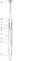
以下、図面を参照して本発明の実施の形態について説明する。図1は本発明に係る眼内レンズ移植装置の外観斜視図であり、図2は同断面図である。また、図3は眼内レンズ移植装置の部品分解図である。 Embodiments of the present invention will be described below with reference to the drawings. FIG. 1 is an external perspective view of an intraocular lens implantation apparatus according to the present invention, and FIG. 2 is a cross-sectional view thereof. FIG. 3 is an exploded view of the intraocular lens implantation apparatus.
先ず、はじめに本発明が適用される眼内レンズ移植装置1について説明する。本発明が適用される眼内レンズ移植装置1の概略構成は、眼内レンズ2の収納部たるカートリッジ3と、前記カートリッジ3が一端に係止され他端に把持フランジ4が固定された本体たる筒状のハンドピース5と、前記ハンドピース5に挿通され押し棒13と一体化されたプランジャー6からなる。そして、前記プランジャー6の先端部6aは基底部7と突起部8とから構成されている。
First, an intraocular
カートリッジ3は、その内部に眼内レンズ2を収納し、眼球組織の切開創口よりその先端部を眼球内に挿入して眼球内にレンズを放出するためのものであり、概略中空の筒状をしていて、先細となるように形成されている。そして、カートリッジ3の術者側の端部は眼内レンズ挿入口3aに供され、先端側である他端は眼内レンズ放出口3bに供される。挿入口3aは眼内レンズ2を折り畳んでカートリッジ3内に装填するためのものであり、筒部には挿入溝3cが設けられている。この挿入溝3cがあることにより挿入器具(図示せず)を用いて眼内レンズ2を折り畳んだ状態でカートリッジ3内に容易に装填することができる。また、カートリッジ3の先端に位置する放出口3bは眼球組織の切開創口への挿入をし易くするため、切り口が斜めに形成されている。さらに、カートリッジ3の側面にはカートリッジ3をハンドピース5に係止するための翼部3dが2箇所に設けられている。
The
なお、本実施例では眼内レンズの収納部たるカートリッジ3と、本体たるハンドピース5を別体として構成しているが、カートリッジ3とハンドピース5を一体として構成することもできる。
In this embodiment, the
ハンドピース5は、その先端側に近い側面にカートリッジ3の翼部3dを案内する案内路を有する断面半円弧状の案内部5aが形成されており、案内部5aの先端側には、カートリッジ3の翼部3dを係止可能とする係止部5bが設けられている。また、ハンドピース5の他端には、押し棒13の外周面とハンドピース5の内周面との間にボールブシュ9が装着されている。さらに、ハンドピース5の他端にはキャップ11が固定され、このキャップ11には術者の把持を容易にするための把持フランジ4が固定されている。
The
プランジャー6には締結具12により押し棒13が一体化され、前述したハンドピース5とボールブッシュ9および把持フランジ4内に挿通されている。そして、押し棒13の術者側には、押し棒13の押し引きを容易にするためのエンドプレート14が固定されている。
A
ボールブッシュ9は円筒状のボールホルダー15の周囲に複数の穴15aを設け、それら複数の各穴15aに金属製のボール16を配置したものであり、キャップ11内での押し棒13の移動を低摩擦で行なうことができる一種の軸受である。すなわち、キャップ11内の押し棒13の移動を転がり抵抗により行なうことができるものであり、押し棒13の移動に要する駆動力が小さくて済む利点がある。ただし、押し棒13に必要とされる移動は軸方向の移動だけであり、周方向の回転は不必要である。そこで、押し棒13の外周面1箇所に溝13aが設けられ、該溝13aに対応してボールホルダー15には前記穴15aとは別の穴15bが設けられ、該穴15b内に係止された金属ボール17と前記溝13aが係合されている。また、金属ボール17は、ハンドピース5の内周面1箇所に設けられた軸方向の溝5cとも係合されている。このことにより、押し棒13はキャップ11内を軸方向に移動することはできるが、周方向に回転することが出来ないようにされている。
The
さらに、ボールブッシュ9のボールホルダー15には周囲4箇所に長穴15cが設けられており、該長穴内15cにはキャップ11の内径と押し棒13の外径とで形成される隙間より若干大きな寸法を有する抵抗制御部材18が配置されている。具体的にはシリコンゴム等からなる棒状の弾性体18が配置されている。このことにより、押し棒13をキャップ11内において軸方向に移動させるとき、押し棒13には適度な大きさの滑り抵抗を付与することができ、押し棒13の移動抵抗や速度を制御することができる。このように押し棒13に適度な滑り抵抗を与えるのは、押し棒13の抵抗が余りにも小さいと、押し棒13と一体化されたプランジャー6の位置が自己保持されず、眼内レンズ2を眼球内へ挿入して移植する際の操作が困難になるからである。
Further, the
本発明が適用される眼内レンズ移植装置1は、上述したように抵抗制御部材18付きボールブッシュ9を用いて押し棒13の移動抵抗や速度を制御することが可能なため、眼内レンズ2が眼球内へ急激に放出されることを防止できる。また、抵抗制御部材18がボールホルダー15の長穴15c内に埋め込まれているため、抵抗制御部材18がハンドピース5やキャップ11内に埋め込まれたものに比較すると、耐久性を向上することができる。さらに、ボールホルダー15の長穴15c内に埋め込む棒状の抵抗制御部材18を弧状に反らせた形状とすれば、より一層耐久性を向上させることができる。
The intraocular
なお、上述した眼内レンズ移植装置1は、押し棒13の移動抵抗や速度を制御する部材としてボールブッシュ9を使用しているが、ボールブッシュ9の代わりに低摩擦材料である樹脂製の滑り軸受を用いることも可能である。低摩擦係数を有する樹脂材料としては、テフロン(登録商標)やピーク材を挙げることができる。これらの樹脂材料で製作された滑り軸受は、ボールブッシュ9に較べると安価であり、製作費用を抑制できる利点がある。
The intraocular
ここで、本発明が適用される眼内レンズ移植装置1は、医療用器具であるため器具の構成部材の材質は物理的・化学的に安定な材料であることが要求される。特に、眼内に挿入される部位に使用される材料は、生物学的に安全性の保証のなされたものでなければならない。例えば、FDA(Food and Drug Administration)でインプラント材料として認定されたものやISO(International Standardization Organization)でインプラント材料として規格化されたもの、あるいはISO10993に従って行なわれた試験の結果、問題のない材料であることが確認されたものであることが求められる。これらの要求を満たす材料として、例えばカートリッジの材料としてはポリエチレンやポリプロピレンなどがあり、プランジャーの材料としてはチタン合金やマルテンサイト系ステンレス鋼がある。
Here, since the intraocular
また、本発明が適用される眼内レンズ移植装置1は、術者が片手で操作することを前提とするものであり、眼内レンズ移植装置1の寸法および重量も重要な性能である。すなわち、寸法が大き過ぎたり、逆に小さ過ぎたりすると片手操作が難しくなる。また、重量が軽くて不都合なことはないが、重量が重過ぎると術者の負担が増大する。経験的事実によれば、押し棒13を引いた状態の装置全体の最大長さは、200mm以下が好ましく、160mm以下が特に好ましい。また、眼内レンズ移植装置全体1の重量は40g以下であることが好ましく、より好ましくは30g以下であることが求められている。
In addition, the intraocular
そこで、本発明が適用される眼内レンズ移植装置1には、比強度の高い材料、すなわち単位重量当たりの強度の高い材料が主たる部材の材料として用いられる。具体的には主としてチタン合金が使用されるが、ビス等の小部品にはステンレス鋼材も使用される。このような材料を使用することにより発錆がなく、軽量であるうえに、以下に示すような耐久性にも優れた眼内レンズ移植装置1を実現することができる。
Therefore, in the intraocular
本発明が適用される眼内レンズ移植装置1は、通常想定される使用条件において、保守作業の必要性がない。別段の保守作業を行なうことなく2年以上の期間にわたって所期の性能を保持できる。また、135℃で15分間の高圧殺菌処理をする場合、繰り返し200回以上処理を行なっても所期の性能を保持できることが確認されている。さらに、プランジャー6の先端に800gのスラスト負荷を与えた状態で、100回以上繰り返し動作させた場合においても、性能を保持できることが確認されている。その他、プランジャー6に負荷を与えない無負荷状態で、1万回の繰り返し動作に耐えることが確認されている。
The intraocular
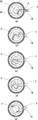
次に、本発明の核心部分であるプランジャー6の先端部6aの形状について図4に基づいて説明する。プランジャー6の先端部6aは基底部7と突起部8とから構成されている。図4に示すプランジャー6の先端形状は各々異なる実施例を示すものであり、(a)は基底部7の先端の上部中央に突起部8を設けたものである。また、(b)は基底部7の先端の下部右下に突起部8を設けたものであり、(c)は基底部7の先端の下部中央に突起部8を設けたものである。いずれの実施例も先端が平面をなす基底部7の先端の1箇所に突起部8が設けられ、該突起部8がプランジャー6の軸芯から偏位した位置に設けられていることは共通している。ただし、(a)と(c)に示す突起8の位置はプランジャー6の先端面の縦軸中心6b上に設けられているのに対し、(b)に示す突起8の位置はプランジャー6の先端面の縦軸中心6bから偏位した位置に設けられている点で異なっている。
Next, the shape of the
なお、図4に示す各実施例において、プランジャー6の先端部6aや突起部8の寸法は任意の値を採用できるものであるが、眼内レンズ2は眼内へ挿入されるものであることから、プランジャー6の先端部6aや突起部8の寸法にも適正値がある。たとえば、眼内レンズ2の代表的な寸法は、光学部直径6mm、光学部の中心厚さ0.7mm、光学部の周辺厚さ0.25mmである。この場合、プランジャー6の先端部6aの幅は1.2mm、高さは1.5mm程度が適正な寸法となる。また、突起部8の直径および高さは0.3mm程度が適正な寸法となる。
In each of the embodiments shown in FIG. 4, the
プランジャー6は押し棒13と一体化され、術者によって押し引きされるものである。そして、プランジャー6の先端部6aにより、カートリッジ3内に収納された眼内レンズ2を押し出して眼内に移植するものである。ここで、眼内レンズは折り曲げ可能な材料からできており、弾性に富んでいる。したがって、眼内レンズ2の周辺部2aを押圧すると、眼内レンズの周辺部2aは比較的容易に変形するが、押圧力を除けば変形前の形状に復元する。図4に示したプランジャー6の先端部6aは、いずれも眼内レンズの周辺部2aを押圧するためのものであり、突起部8を眼内レンズの周辺部2aに当接して、先ず突起部8により眼内レンズの周辺部2aを押圧する。突起部8の形状は、半球形状や半球と円柱を組み合わせた形状とするのが最適であり、面積も小さいことから突起部8が当接された眼内レンズの周辺部2aは比較的高い面圧になり、突起部8が眼内レンズの周辺部2aに喰い込むようにして眼内レンズの当接部を弾性変形させる。突起部8による眼内レンズ2の弾性変形が進むと眼内レンズの周辺部2aは、基底部7の先端の平面7aに当接することになる。したがって、突起部8による眼内レンズ2の変形量は、基底部先端面7aからの突起部8の高さによって制限されることになる。さらにプランジャー6により眼内レンズ2を押圧すると、基底部7の先端の平面7aによって眼内レンズの周辺部2aが押圧されることになる。そのため突起部8の高さ寸法は眼内レンズ2の材料の弾性限度を超えないように設定されている。
The
なお、突起部8の形状は、半球形状や半球と円柱を組み合わせた形状に限られるものではなく、円柱形状や楕円柱形状であっても構わない。
In addition, the shape of the
突起部8をプランジャー6の軸芯から偏位した位置、すなわちプランジャー6の軸芯からオフセットした基底部先端面7aの周辺部に設けることとしたのは、U字形状に折り曲げられた眼内レンズの周辺部2aに突起部8を容易に当接可能にするためである。かかる理由から、突起部8を設ける位置は基底部先端面7aの周辺部であればよく、図4の(a)(b)(c)に示す実施例に限られるものではない。
The
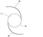
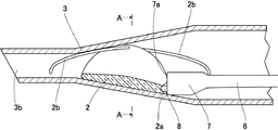
次に、本発明が適用された眼内レンズ移植装置1を用いて眼内レンズ2を眼球内に挿入移植する際の作用について図5〜図7を用いて説明する。図5は眼内レンズ2の平面視を示すものであり、眼内レンズ2は概略円板形状を有するレンズ本体である光学部2と、該光学部2の位置固定のためのひげ状をした2本の支持部2bとからなる。そして、光学部2も含めて軟質の樹脂材料から製作されており、容易に弾性変形させることができる。図6は眼内レンズ2をカートリッジ3内に略U字形状に折り畳んで収納し、プランジャー6の先端部により押圧して移動させる状態を示している。具体的にはカートリッジ3の軸方向断面図である。図7は図6中のA−A矢視図である。
Next, the operation when the
眼内レンズ2は、2本の支持部2bの取付け部をU字の両端になるようにしてカートリッジ3内に収納される。したがって、カートリッジ3内に収納された後では、図6に示すように2本の支持部2bはカートリッジ3の軸方向に沿って前後に配置されることになる。プランジャー6の先端部6aは、ひげ状の支持部2bを避けるようにして眼内レンズ2の光学部の周辺部2aに当接される。
The
術者は眼内レンズ2が収納されたカートリッジ3を眼内レンズ移植装置1に装着した後、片手操作により眼内レンズ2をカートリッジ3の先端部から押し出して眼球内に移植する。具体的には、図8の各図に示す手順により移植を行なう。先ず、図6に示すようにプランジャー6の基底部7の先端に設けられた突起部8を光学部の周辺部2aに当接して押圧するとともに、プランジャー6の基底部7の先端の平面部7aでも押圧して眼内レンズ2をカートリッジ3の先端付近まで移動させる。このとき眼内レンズ2はカートリッジ3の内壁面と摺動することにより摺動抵抗を受ける。そして、この摺動抵抗よりも大きな押圧力がプランジャー6から与えられると、眼内レンズ2はカートリッジ3内を先端側に向かって移動する。
The surgeon attaches the
ここで、眼内レンズ2は軟質の弾性材料で製作されているため、プランジャー6の先端の突起部8が光学部の周辺部2aを強く弾性変形させるとともに、プランジャー6の基底部7の先端面7aも光学部の周辺部2aをある程度の押圧力で弾性変形させる。その結果、あたかも眼内レンズの周辺部2aにプランジャー6の先端部6aが固定されたようになり、プランジャー6の先端の突起部8がアンカーのような効果を奏することになる。したがって、術者は眼内レンズ2を意図した姿勢を保持したままカートリッジ3内で眼内レンズ2を容易に移動させることができる。
Here, since the
次に、図8に基づいて眼内レンズ2を眼球内へ挿入移植する過程を簡単に説明する。(a)に示すように眼球の切開創口19にカートリッジ3の放出口3bを挿入し、先端側の支持部2bを眼内に押出す。続いて(b)(c)に示すように眼内レンズ移植装置1全体をゆっくり回転させながら、プランジャー6によって眼内レンズ2を少しずつ押出して光学部2を開放する。この段階においては眼球内で眼内レンズ2が最適な位置に移植されるとは限らない。多くの場合、眼球内における眼内レンズ2の位置調整操作が必要になる。(d)はこの様子を示すものであり、プランジャー6の先端に設けられた突起部8が、未だ光学部の周辺部2aに食い込んだ状態にあることを利用してプランジャー6により眼内レンズ2の位置調整を行なっているところである。そして、眼内レンズ2の位置調整が完了した後(e)に示すように他の支持部2bをカートリッジ3から開放する。
Next, a process of inserting and implanting the
このように眼内レンズ2をカートリッジ3内において移動させる際、光学部の周辺部2aをプランジャー6の先端の突起部8により押圧することにより生じるアンカー効果を利用して眼内レンズ2の姿勢を容易に制御できる。さらに、眼内レンズ2が眼球組織の切開創口19より眼球内に挿入されたカートリッジ3の放出口3bから放出され、眼球内においてレンズ本来の姿である平板状に復元した後においても、前記アンカー効果はしばらくの間残存するので、眼内レンズ2を眼球内の所望の位置に位置合わせする際の操作が容易になる。
Thus, when the
次に、図4とは異なり、プランジャー6の先端部に2つの突起部を設けた実施例について説明する。図9は先端部に2つの突起部を設けたプランジャー6を示し、(a)は正面図であり、(b)は側面図である。正面図の右下に設けられた突起部8aは、図4に示す突起部と同様のアンカー効果を発揮させるためのものであり、眼内レンズ2の周辺部に当接して眼内レンズ2を弾性変形させ、眼内レンズ2をカートリッジ3から眼球内へ押し出すものである。プランジャー6の先端部6aの幅Wを1.2mm、高さHを1.5mmとすると、突起部8aの直径は0.2mm、高さは0.25mm程度が適正な寸法となる。また、正面図の上部中央に設けられた突起部8bは、眼内レンズ2をカートリッジ3から眼球内へ放出した後、眼球内において眼内レンズ2の表面に当接して眼内レンズ2の位置調整を行うために供せられるものである。この突起部8bを設けることにより眼球内における眼内レンズ2の位置調整を容易に行うことが可能となる。突起部8bの直径は0.26mm、高さは0.43mm程度が適正な寸法となる。
Next, different from FIG. 4, an embodiment in which two protrusions are provided at the tip of the
以上、本発明をいくつかの実施例に基づいて説明したが、本発明は上記の実施例に限定されるものではなく、種々の変形実施が可能である。例えば、上記実施例においてはプランジャー6の移動を軸方向に直接的に押し引きする眼内レンズ移植装置1に適用した例を挙げたが、プランジャー6の移動を押し棒の回転によって行なうようにした、ねじ式の眼内レンズ移植装置に適用できることは言うまでもない。
As mentioned above, although this invention was demonstrated based on some Examples, this invention is not limited to said Example, Various deformation | transformation implementation is possible. For example, in the above embodiment, the example in which the movement of the
また、図6〜図8においては、眼内レンズを略U字形状に折り畳んだ例を挙げて説明したが、眼内レンズを折り畳む際の断面形状は略U字形状に限定されるものではなく、種々の断面形状に折り畳んでも適用できる。 6-8, the intraocular lens has been described as an example of being folded into a substantially U shape, but the cross-sectional shape when the intraocular lens is folded is not limited to a substantially U shape. It can also be applied by folding in various cross-sectional shapes.
1 眼内レンズ移植装置
2 眼内レンズ
3 収納部(カートリッジ)
5 本体(ハンドピース)
6 プランジャー
6a 先端部
7 基底部
8 突起部(突起)
DESCRIPTION OF
5 Body (handpiece)
6 Plunger
Claims (5)
Priority Applications (1)
| Application Number | Priority Date | Filing Date | Title |
|---|---|---|---|
| JP2006550684A JP5114949B2 (en) | 2004-12-27 | 2005-12-19 | Intraocular lens implantation device |
Applications Claiming Priority (4)
| Application Number | Priority Date | Filing Date | Title |
|---|---|---|---|
| JP2004377175 | 2004-12-27 | ||
| JP2004377175 | 2004-12-27 | ||
| PCT/JP2005/023246 WO2006070628A1 (en) | 2004-12-27 | 2005-12-19 | Intraocular lens implanting device |
| JP2006550684A JP5114949B2 (en) | 2004-12-27 | 2005-12-19 | Intraocular lens implantation device |
Publications (2)
| Publication Number | Publication Date |
|---|---|
| JPWO2006070628A1 JPWO2006070628A1 (en) | 2008-06-12 |
| JP5114949B2 true JP5114949B2 (en) | 2013-01-09 |
Family
ID=36614747
Family Applications (1)
| Application Number | Title | Priority Date | Filing Date |
|---|---|---|---|
| JP2006550684A Active JP5114949B2 (en) | 2004-12-27 | 2005-12-19 | Intraocular lens implantation device |
Country Status (4)
| Country | Link |
|---|---|
| US (1) | US8460311B2 (en) |
| EP (1) | EP1832247B1 (en) |
| JP (1) | JP5114949B2 (en) |
| WO (1) | WO2006070628A1 (en) |
Families Citing this family (50)
| Publication number | Priority date | Publication date | Assignee | Title |
|---|---|---|---|---|
| WO2006070628A1 (en) | 2004-12-27 | 2006-07-06 | Hoya Corporation | Intraocular lens implanting device |
| WO2006080191A1 (en) | 2005-01-26 | 2006-08-03 | Hoya Corporation | Intraocular lens insertion device |
| JP4836046B2 (en) | 2005-02-24 | 2011-12-14 | Hoya株式会社 | Intraocular lens insertion device |
| JP4922174B2 (en) | 2005-09-28 | 2012-04-25 | Hoya株式会社 | Intraocular lens insertion device |
| JP4877643B2 (en) | 2005-12-08 | 2012-02-15 | Hoya株式会社 | Intraocular lens insertion device |
| JP5236638B2 (en) | 2007-05-30 | 2013-07-17 | Hoya株式会社 | Intraocular lens insertion device |
| CN101677853B (en) | 2007-05-30 | 2012-04-18 | Hoya株式会社 | Intraocular lens inserting tool |
| JP5086713B2 (en) | 2007-07-11 | 2012-11-28 | Hoya株式会社 | Intraocular lens insertion device |
| JP2009028223A (en) * | 2007-07-26 | 2009-02-12 | Hoya Corp | Intraocular lens inserting instrument |
| US8105332B2 (en) * | 2007-10-30 | 2012-01-31 | Novartis Ag | Lens delivery system |
| JP5086062B2 (en) * | 2007-12-29 | 2012-11-28 | 株式会社ニデック | Intraocular lens insertion device |
| BRPI0907725B8 (en) | 2008-02-07 | 2023-04-04 | Alcon Inc | lens distribution system cartridge |
| JP5254669B2 (en) | 2008-06-05 | 2013-08-07 | Hoya株式会社 | Intraocular lens insertion device and cartridge |
| JP5470753B2 (en) | 2008-06-17 | 2014-04-16 | Hoya株式会社 | Intraocular lens insertion device |
| JP5323420B2 (en) | 2008-08-21 | 2013-10-23 | Hoya株式会社 | Intraocular lens insertion device |
| JP5416379B2 (en) | 2008-09-04 | 2014-02-12 | Hoya株式会社 | Intraocular lens insertion device |
| US8348954B2 (en) * | 2008-09-16 | 2013-01-08 | Warsaw Orthopedic, Inc. | Electronic guidance of spinal instrumentation |
| US8808308B2 (en) | 2008-10-13 | 2014-08-19 | Alcon Research, Ltd. | Automated intraocular lens injector device |
| US8801780B2 (en) | 2008-10-13 | 2014-08-12 | Alcon Research, Ltd. | Plunger tip coupling device for intraocular lens injector |
| SG172876A1 (en) | 2009-01-07 | 2011-08-29 | Hoya Corp | Intraocular lens insertion device |
| KR101339069B1 (en) | 2009-02-11 | 2013-12-09 | 알콘 리서치, 리미티드 | Automated intraocular lens injector device |
| JP5735531B2 (en) | 2010-04-08 | 2015-06-17 | Hoya株式会社 | Ocular graft insertion device |
| US8308799B2 (en) * | 2010-04-20 | 2012-11-13 | Alcon Research, Ltd. | Modular intraocular lens injector device |
| JP5511530B2 (en) | 2010-06-10 | 2014-06-04 | Hoya株式会社 | Intraocular lens insertion device |
| EP2601996A4 (en) * | 2010-08-03 | 2017-05-10 | Hoya Corporation | Therapeutic instrument and attachment thereof |
| EP2567674B1 (en) * | 2011-09-07 | 2015-05-06 | SDI Surgical Device International GmbH | Modular intraocular lens injector |
| US20130245634A1 (en) * | 2011-12-23 | 2013-09-19 | Kyle Brown | Plunger system for intraocular lens surgery |
| US8657835B2 (en) | 2012-01-27 | 2014-02-25 | Alcon Research, Ltd. | Automated intraocular lens injector device |
| US9724191B2 (en) | 2012-06-04 | 2017-08-08 | Alcon Pharmaceuticals, Ltd. | Intraocular lens inserter |
| NZ702909A (en) | 2012-06-12 | 2017-01-27 | Altaviz Llc | Intraocular gas injector |
| WO2014084355A1 (en) * | 2012-11-29 | 2014-06-05 | 興和株式会社 | Intraocular lens insertion device |
| JP6057749B2 (en) * | 2013-02-04 | 2017-01-11 | 興和株式会社 | Intraocular lens insertion device |
| US10265164B2 (en) * | 2013-03-06 | 2019-04-23 | Johnson & Johnson Surgical Vision, Inc. | Atraumatic IOL insertion cartridge opening |
| EP2873391A1 (en) * | 2013-11-15 | 2015-05-20 | Atttinger Technik AG | Intraocular lens injector, method for folding an intraocular lens and intraocular lens injector system |
| BR102014006114B1 (en) * | 2014-03-14 | 2022-05-10 | Antônio Francisco Neves Filho | Mechanical or biological heart valve stent for minimally invasive valve replacement procedure and stent delivery device |
| WO2015154049A1 (en) | 2014-04-04 | 2015-10-08 | Altaviz, Llc | Intraocular lens inserter |
| US10588780B2 (en) | 2015-03-04 | 2020-03-17 | Alcon Inc. | Intraocular lens injector |
| EP3351212B2 (en) | 2015-09-16 | 2023-08-23 | HOYA Corporation | Intraocular lens insertion tool |
| JP6646987B2 (en) | 2015-09-16 | 2020-02-14 | Hoya株式会社 | Intraocular lens insertion device |
| US10172706B2 (en) | 2015-10-31 | 2019-01-08 | Novartis Ag | Intraocular lens inserter |
| US11547555B2 (en) | 2015-12-17 | 2023-01-10 | Atrion Medical Products, Inc. | Intraocular lens delivery device and method of use |
| US10722347B2 (en) | 2015-12-17 | 2020-07-28 | Atrion Medical Products, Inc. | Intraocular lens delivery device and method of use |
| AU2017288642B2 (en) | 2016-06-28 | 2022-05-19 | Hoya Corporation | Intraocular lens insertion tool |
| US11000367B2 (en) | 2017-01-13 | 2021-05-11 | Alcon Inc. | Intraocular lens injector |
| US10568735B2 (en) | 2017-01-13 | 2020-02-25 | Alcon Inc. | Intraocular lens injector |
| WO2019236355A1 (en) | 2018-06-05 | 2019-12-12 | Atrion Medical Products, Inc. | Intraocular lens delivery device and method of use |
| US11224537B2 (en) | 2018-10-19 | 2022-01-18 | Alcon Inc. | Intraocular gas injector |
| US11324590B2 (en) | 2018-12-19 | 2022-05-10 | Alcon Inc. | Collapsing push injector with hydraulic damping |
| CH715932A1 (en) | 2019-03-15 | 2020-09-15 | Medicel Ag | Injector for intraocular lenses and punches for an injector for intraocular lenses. |
| JP7387994B2 (en) | 2019-03-26 | 2023-11-29 | 株式会社ニデック | Intraocular lens insertion device |
Citations (2)
| Publication number | Priority date | Publication date | Assignee | Title |
|---|---|---|---|---|
| WO2002071982A1 (en) * | 2001-01-26 | 2002-09-19 | Advanced Medical Optics, Inc. | Tepped oil insertion cartridge |
| JP2004188194A (en) * | 2002-12-09 | 2004-07-08 | Anton Meyer & Co Ag | Piston needle for intraocular lens injector |
Family Cites Families (180)
| Publication number | Priority date | Publication date | Assignee | Title |
|---|---|---|---|---|
| US2761446A (en) | 1955-03-30 | 1956-09-04 | Chemical Specialties Co Inc | Implanter and cartridge |
| US4205747A (en) * | 1978-09-05 | 1980-06-03 | Cilco, Inc. | Lens storage device |
| US4269307A (en) * | 1979-08-09 | 1981-05-26 | Iolab Corporation | Intraocular lens storage assembly |
| US4702244A (en) | 1982-02-05 | 1987-10-27 | Staar Surgical Company | Surgical device for implantation of a deformable intraocular lens |
| US4573998A (en) * | 1982-02-05 | 1986-03-04 | Staar Surgical Co. | Methods for implantation of deformable intraocular lenses |
| US4423809A (en) * | 1982-02-05 | 1984-01-03 | Staar Surgical Company, Inc. | Packaging system for intraocular lens structures |
| US4608049A (en) | 1982-06-28 | 1986-08-26 | Kelman Charles D | Intraocular lens and method of inserting an intraocular lens into an eye |
| US4634423A (en) * | 1984-04-30 | 1987-01-06 | Bailey Jr Paul F | Ophthalmological method and instrument for implantation of posterior chamber intraocular lens |
| US4787904A (en) | 1984-07-06 | 1988-11-29 | Severin Sanford L | Hydrophillic intraocular lens |
| US4699140A (en) | 1985-07-10 | 1987-10-13 | Iolab Corporation | Instrument for inserting an intraocular lens |
| US4681102A (en) * | 1985-09-11 | 1987-07-21 | Bartell Michael T | Apparatus and method for insertion of an intra-ocular lens |
| US4750498A (en) * | 1986-02-21 | 1988-06-14 | Coopervision, Inc. | Method and tool for inserting an intraocular lens |
| DE3610925C2 (en) | 1986-03-24 | 1994-11-03 | Michael Ulrich Prof D Dardenne | Device for folding an implantable intraocular lens, in particular provided with two plastic haptic plates on the side, and for inserting the folded intraocular lens into the eye |
| US4697697A (en) | 1986-08-18 | 1987-10-06 | Coopervision, Inc. | Method and apparatus for packaging an intraocular lens |
| US4919130A (en) * | 1986-11-07 | 1990-04-24 | Nestle S.A. | Tool for inserting compressible intraocular lenses into the eye and method |
| US4747404A (en) * | 1986-11-10 | 1988-05-31 | Kresge Eye Institute Of Wayne State University | Foldable intraocular lens inserter |
| US4763650A (en) | 1987-01-20 | 1988-08-16 | Hauser Stephen G | Instrument for inserting a deformable lens into the eye |
| US4994028A (en) * | 1987-03-18 | 1991-02-19 | Endocon, Inc. | Injector for inplanting multiple pellet medicaments |
| US4988352A (en) * | 1987-03-26 | 1991-01-29 | Poley Brooks J | Method and apparatus for folding, freezing and implanting intraocular lens |
| US5176686A (en) * | 1987-03-26 | 1993-01-05 | Poley Brooks J | Apparatus for packaging, folding, rigidifying and inserting an intraocular lens |
| US4769034A (en) | 1987-03-26 | 1988-09-06 | Poley Brooks J | Folded intraocular lens, method of implanting folded intraocular lens |
| US4819631A (en) * | 1987-03-26 | 1989-04-11 | Poley Brooks J | Folded intraocular lens, method of implanting it, retainer, and apparatus for folding lens |
| US4781719A (en) | 1987-07-28 | 1988-11-01 | Kelman Charles D | Method of inserting an intraocular lens into an eye |
| US4759359A (en) * | 1987-08-31 | 1988-07-26 | Allergan, Inc. | Lens implantation instrument |
| US4834094A (en) * | 1987-10-07 | 1989-05-30 | Patton Medical Technologies, Inc. | "Canoe" apparatus for inserting intra-ocular lens into the eye |
| US4765329A (en) | 1987-10-19 | 1988-08-23 | Cumming, Redwitz & Wilson, Inc. | Intraocular lens insertion instrument |
| US4880000A (en) | 1987-12-15 | 1989-11-14 | Iolab Corporation | Lens insertion instrument |
| US4934363A (en) * | 1987-12-15 | 1990-06-19 | Iolab Corporation | Lens insertion instrument |
| US4836201A (en) * | 1988-03-24 | 1989-06-06 | Patton Medical Technologies, Inc. | "Envelope" apparatus for inserting intra-ocular lens into the eye |
| US4862885A (en) | 1988-05-25 | 1989-09-05 | Cumming J Stuart | Instrument for inserting a deformable intraocular lens into the eye |
| EP0363213A3 (en) | 1988-10-07 | 1990-12-12 | Ioptex Research Inc. | Intraocular lens insertion instrument |
| US5066297A (en) | 1989-01-23 | 1991-11-19 | Cumming J Stuart | Intraocular lens insertion device |
| US4976716A (en) | 1989-01-23 | 1990-12-11 | Cumming J Stuart | Intraocular lens insertion device |
| US4955889A (en) | 1989-02-06 | 1990-09-11 | Allergan, Inc. | Apparatus for inserting a lens into an eye and method for using same |
| US5098439A (en) * | 1989-04-12 | 1992-03-24 | Allergan, Inc. | Small incision intraocular lens insertion apparatus |
| US5222972A (en) * | 1989-04-12 | 1993-06-29 | Allergan, Inc. | Small incision intraocular lens insertion apparatus |
| US5171241A (en) | 1989-06-09 | 1992-12-15 | Ioptex Research Inc. | Device for folding an intraocular lens and holding it in the folded state |
| DE4030492C1 (en) | 1990-09-26 | 1991-09-05 | Adatomed Pharmazeutische Und Medizintechnische Gesellschaft Mbh, 8000 Muenchen, De | |
| DE4039119C1 (en) | 1990-12-07 | 1991-09-05 | Dieter Dr.Med. 8904 Friedberg De Klaas | |
| DE4108303C2 (en) * | 1991-03-14 | 1993-11-04 | Adatomed Pharma & Med | METHOD AND DEVICE FOR INSERTING A RUBBER-ELASTIC INTRAOCULAR LENS IN AN IMPLANTATION TOOL |
| DE4110278A1 (en) | 1991-03-28 | 1992-10-01 | Geuder Hans Gmbh | Surgical instrument for implanting soft lenses in eye - has guide sleeve attached to handle by quick-action coupling |
| US5123905A (en) * | 1991-06-07 | 1992-06-23 | Kelman Charles D | Intraocular lens injector |
| US5178622A (en) * | 1991-11-01 | 1993-01-12 | Lehner Ii Robert H | Instrument for implanting a soft intraocular lens |
| US5190552A (en) * | 1992-02-04 | 1993-03-02 | Kelman Charles D | Slotted tube injector for an intraocular lens |
| US5571113A (en) | 1992-05-18 | 1996-11-05 | Henry H. McDonald | Surgical probe with tips for plastic lens implantation in the eye |
| US5242450A (en) | 1992-05-18 | 1993-09-07 | Henry H. McDonald | Eye implantable lens haptics twist apparatus |
| US5395378A (en) * | 1992-05-18 | 1995-03-07 | Henry H. McDonald | Eye implantable lens haptics insertion and twist apparatus |
| US5304182A (en) * | 1992-09-23 | 1994-04-19 | Kabi Pharmacia Ophthalmics, Inc. | Apparatus and method for curling and inserting flexible intraocular lenses |
| US5728102A (en) * | 1992-09-30 | 1998-03-17 | Staar Surgical Company, Inc. | Disposable intraocular lens insertion system |
| AU692425B2 (en) * | 1992-09-30 | 1998-06-11 | Staar Surgical Company, Inc. | A lens cartridge for use in a surgical lens inserting device |
| US5860984A (en) * | 1992-09-30 | 1999-01-19 | Staar Surgical Company, Inc. | Spring biased deformable intraocular injecting apparatus |
| US5499987A (en) * | 1992-09-30 | 1996-03-19 | Staar Surgical Company | Deformable intraocular lens cartridge |
| US5616148A (en) * | 1992-09-30 | 1997-04-01 | Staar Surgical Company, Inc. | Transverse hinged deformable intraocular lens injecting apparatus |
| US6712848B1 (en) * | 1992-09-30 | 2004-03-30 | Staar Surgical Company, Inc. | Deformable intraocular lens injecting apparatus with transverse hinged lens cartridge |
| US5928245A (en) * | 1992-09-30 | 1999-07-27 | Staar Surgical Company, Inc. | Deformable intraocular lens injecting apparatus with transverse hinged lens cartridge |
| US6059791A (en) * | 1992-09-30 | 2000-05-09 | Staar Surgical Company, Inc. | Deformable intraocular lens injection system, and method thereof |
| US5772666A (en) * | 1992-09-30 | 1998-06-30 | Staar Surgical Company, Inc. | Deformable intraocular lens injecting apparatus with deformable tip plunger |
| US6022358A (en) | 1992-09-30 | 2000-02-08 | Staar Surgical Company, Inc. | Deformable intraocular lens injecting device |
| US5902307A (en) * | 1992-09-30 | 1999-05-11 | Starr Surgical Company, Inc. | Method of loading an intraocular lens into a lens injecting apparatus, and implanting the intraocular lens through a small incision made in an eye |
| US5807400A (en) | 1992-09-30 | 1998-09-15 | Staar Surgical Company, Inc. | Deformable intraocular lens insertion system |
| US5876440A (en) * | 1992-09-30 | 1999-03-02 | Staar Surgical Company, Inc. | Methods of implantation of deformable intraocular lens |
| US6506195B2 (en) * | 1992-09-30 | 2003-01-14 | Staar Surgical Company, Inc. | Deformable intraocular lens insertion system |
| US6001107A (en) | 1992-09-30 | 1999-12-14 | Staar Surgical Company, Inc. | Deformable intraocular lens injecting apparatus |
| US5620450A (en) * | 1992-09-30 | 1997-04-15 | Staar Surgical Company, Inc. | Transverse hinged deformable intraocular lens injecting apparatus |
| US6056757A (en) | 1992-09-30 | 2000-05-02 | Staar Surgical Company, Inc. | Implantation device with deformable nozzle tip for implanting a deformable intraocular lens |
| US5941886A (en) | 1992-09-30 | 1999-08-24 | Staar Surgical Company, Inc. | Hingeless lens cartridges for insertion of deformable intraocular lens |
| US5281227A (en) * | 1992-11-09 | 1994-01-25 | Allergan, Inc. | Lens case with IOL folding device |
| US5275604A (en) * | 1992-12-03 | 1994-01-04 | Kabi Pharmacia Ophthalmics, Inc. | Contoured duct apparatus and method for insertion of flexible intraocular lens |
| US5653715A (en) * | 1993-03-09 | 1997-08-05 | Chiron Vision Corporation | Apparatus for preparing an intraocular lens for insertion |
| US5468246A (en) * | 1993-07-02 | 1995-11-21 | Iovision, Inc. | Intraocular lens injector |
| US5425734A (en) | 1993-07-02 | 1995-06-20 | Iovision, Inc. | Intraocular lens injector |
| JP3459664B2 (en) * | 1993-07-15 | 2003-10-20 | キヤノンスター株式会社 | Deformable intraocular lens insertion device |
| US5582613A (en) | 1993-11-18 | 1996-12-10 | Allergan | Apparatus and methods for controlled insertion of intraocular lenses |
| US5702402A (en) | 1994-04-29 | 1997-12-30 | Allergal | Method and apparatus for folding of intraocular lens |
| WO1995013766A1 (en) | 1993-11-18 | 1995-05-26 | Allergan, Inc. | Deformable lens insertion apparatus |
| US5584304A (en) | 1993-11-18 | 1996-12-17 | Allergan, Inc. | Method of inserting an IOL using a forceps inside a folding tube |
| AU1915595A (en) | 1994-02-09 | 1995-08-29 | Kabi Pharmacia Ophthalmics, Inc. | Rapid implantation of shape transformable optical lenses |
| US6174315B1 (en) * | 1994-02-15 | 2001-01-16 | Staar Surgical Company, Inc. | Spring biased deformable intraocular injecting apparatus |
| US5578042A (en) | 1994-03-14 | 1996-11-26 | Cumming; J. Stuart | Ophthalmic kit and method for lens insertion |
| JP3412106B2 (en) | 1994-07-07 | 2003-06-03 | キヤノンスター株式会社 | Deformable intraocular lens insertion device |
| US5454818A (en) | 1994-07-26 | 1995-10-03 | Alcon Laboratories, Inc. | Intraocular lens folder |
| JP3937181B2 (en) * | 1994-08-05 | 2007-06-27 | ボシュ・アンド・ロム・インコーポレイテッド | Device for inserting a flexible intraocular lens |
| JP3704154B2 (en) * | 1994-11-18 | 2005-10-05 | スター サージカル カンパニー | Intraocular lens insertion system |
| US5803925A (en) | 1995-01-17 | 1998-09-08 | Allergan | IOL insertion apparatus with covalently bonded lubricant |
| KR100461880B1 (en) | 1995-03-14 | 2005-08-29 | 스타 서지컬 컴퍼니 | Deformable intraocular lens injecting device |
| US5643276A (en) * | 1995-10-10 | 1997-07-01 | Allergan | Apparatus and method for providing desired rotational orientation to an intraocular lens |
| US5776138A (en) * | 1996-01-26 | 1998-07-07 | Allergan | Apparatus and methods for IOL insertion |
| US5735858A (en) * | 1996-01-26 | 1998-04-07 | Allergan | IOL insertion apparatus and method for using same |
| FR2749752B1 (en) | 1996-06-17 | 1998-11-20 | Moria Sa | DEVICE FOR FOLDING AND HOLDING A FLEXIBLE INTRAOCULAR IMPLANT |
| US5716364A (en) * | 1996-07-10 | 1998-02-10 | Allergan | IOL insertion apparatus and method for making and using same |
| US6083230A (en) * | 1997-07-30 | 2000-07-04 | Allergan | Method for making IOL insertion apparatus |
| US6283975B1 (en) | 1996-07-10 | 2001-09-04 | Allergan Sales, Inc. | IOL insertion apparatus and method for making and using same |
| US5876406A (en) * | 1996-08-02 | 1999-03-02 | Staar Surgical Company, Inc. | Deformable intraocular lens injecting apparatus with transverse hinged lens cartridge |
| US5766181A (en) * | 1996-08-02 | 1998-06-16 | Staar Surgical Company, Inc. | Spring biased deformable intraocular injecting apparatus |
| US5944725A (en) | 1996-09-26 | 1999-08-31 | Bausch & Lomb Surgical, Inc. | Method and apparatus for inserting a flexible membrane into an eye |
| US5810834A (en) | 1996-10-07 | 1998-09-22 | Chiron Vision Corporation | Tip formation for inserting a flexible membrane into an eye |
| JP3226813B2 (en) | 1996-12-13 | 2001-11-05 | トリンプ・インターナショナル・ジャパン株式会社 | Women's clothing |
| US5947975A (en) * | 1997-03-07 | 1999-09-07 | Canon Staar Co., Inc. | Inserting device for deformable intraocular lens |
| US5919197A (en) * | 1997-05-05 | 1999-07-06 | Surgical Concepts, Inc. | Insertion of multiple folded lens into the eye |
| US5947974A (en) | 1997-12-09 | 1999-09-07 | Allergan | Folding device and method for an intraocular lens |
| US5921989A (en) | 1998-02-12 | 1999-07-13 | Allergan | Lens protector for intraocular lens inserter |
| US6371960B2 (en) * | 1998-05-19 | 2002-04-16 | Bausch & Lomb Surgical, Inc. | Device for inserting a flexible intraocular lens |
| US6010510A (en) | 1998-06-02 | 2000-01-04 | Alcon Laboratories, Inc. | Plunger |
| US6143001A (en) | 1998-06-02 | 2000-11-07 | Alcon Laboratories, Inc. | Asymmetric intraocular lens injection cartridge |
| US6447520B1 (en) * | 2001-03-19 | 2002-09-10 | Advanced Medical Optics, Inc. | IOL insertion apparatus with IOL engagement structure and method for using same |
| DE19904220C2 (en) | 1999-02-03 | 2001-08-30 | Helmut Binder | Injector for folding and inserting an intraocular lens, and containers for storing and transporting the injector |
| US6129733A (en) | 1999-04-15 | 2000-10-10 | Allergan Sales, Inc. | Apparatus for holding intraocular lenses and injectors, and methods for using same |
| US6386357B1 (en) * | 1999-07-12 | 2002-05-14 | Hoya Healthcare Corporation | Soft intraocular lens-folding device and storage case |
| US6248111B1 (en) * | 1999-08-06 | 2001-06-19 | Allergan Sales, Inc. | IOL insertion apparatus and methods for using same |
| JP3728155B2 (en) | 1999-10-05 | 2005-12-21 | キヤノンスター株式会社 | Intraocular lens insertion system |
| JP3944555B2 (en) | 1999-10-06 | 2007-07-11 | キヤノンスター株式会社 | Intraocular lens insertion system |
| US6387101B1 (en) * | 1999-10-22 | 2002-05-14 | Staar Surgical Company, Inc. | Deformable intraocular lens injecting apparatus and method |
| US6312433B1 (en) | 1999-10-22 | 2001-11-06 | Staar Surgical Company, Inc. | Deformable intraocular lens injecting apparatus and method |
| US6251114B1 (en) * | 1999-10-29 | 2001-06-26 | Allergan Sales, Inc. | Rotatable IOL insertion apparatus and method for using same |
| SE9904338D0 (en) * | 1999-11-30 | 1999-11-30 | Pharmacia & Upjohn Ab | Intraocular lens implants |
| US6283976B1 (en) | 2000-05-05 | 2001-09-04 | Allergan Sales Inc. | Intraocular lens implanting instrument |
| GB0011507D0 (en) * | 2000-05-13 | 2000-06-28 | Duckworth & Kent Ltd | Ophthalmic lens injectors |
| FR2814360B1 (en) | 2000-09-28 | 2002-12-27 | Corneal Ind | FLEXIBLE INTRAOCULAR IMPLANT INJECTOR |
| US6500181B1 (en) | 2000-10-17 | 2002-12-31 | Valdemar Portney | Instrument for folding and inserting anterior chamber intraocular lenses |
| US6471708B2 (en) | 2000-12-21 | 2002-10-29 | Bausch & Lomb Incorporated | Intraocular lens and additive packaging system |
| US6540754B2 (en) * | 2001-01-26 | 2003-04-01 | Advanced Medical Optics, Inc. | Apparatus and method for multiply folding and inserting an intraocular lens in an eye |
| FR2822055B1 (en) | 2001-03-16 | 2003-09-12 | Lab Contactologie Appl Lca | INTRAOCULAR LENS INJECTOR |
| EP1391185B1 (en) | 2001-05-25 | 2012-06-27 | Hoya Healthcare Corporation | Storage container having soft intraocular lens folding function |
| JP2002355268A (en) | 2001-06-01 | 2002-12-10 | Nidek Co Ltd | Intraocular lens inserter |
| US6537283B2 (en) * | 2001-08-17 | 2003-03-25 | Alcon, Inc. | Intraocular lens shipping case and injection cartridge |
| ES2331559T3 (en) * | 2001-08-23 | 2010-01-08 | ANTON MEYER & CO. AG | DEVICE FOR IMPLANTING A LENS IN ONE EYE. |
| JP3861138B2 (en) * | 2001-09-04 | 2006-12-20 | キヤノンスター株式会社 | Intraocular lens insertion device |
| US7037312B2 (en) * | 2001-09-07 | 2006-05-02 | Canon-Staar Co., Inc. | Insertion device for deformable intraocular lens |
| FR2833154B1 (en) | 2001-12-12 | 2004-11-19 | Ioltechnologie Production | CASSETTE AND FLEXIBLE INTRAOCULAR LENS INJECTOR AND METHOD FOR INJECTING SUCH LENSES |
| JP3791421B2 (en) | 2002-01-23 | 2006-06-28 | キヤノンスター株式会社 | Intraocular lens insertion device |
| US6723104B2 (en) * | 2002-03-13 | 2004-04-20 | Advanced Medical Optics, Inc. | IOL insertion apparatus and method for using same |
| US6733507B2 (en) * | 2002-04-12 | 2004-05-11 | Advanced Medical Optics, Inc. | Intraocular lens insertion apparatus |
| JP2003325570A (en) | 2002-05-08 | 2003-11-18 | Canon Star Kk | System for inserting intraocular insertion lens |
| JP2003325569A (en) | 2002-05-08 | 2003-11-18 | Canon Star Kk | System for inserting intraocular insertion lens |
| JP2003325572A (en) | 2002-05-08 | 2003-11-18 | Canon Star Kk | System for inserting intraocular insertion lens |
| US7014641B2 (en) * | 2002-05-08 | 2006-03-21 | Canon-Staar Co., Inc. | Insertion device for intraocular lens |
| US7131976B2 (en) | 2002-05-08 | 2006-11-07 | Canon-Staar Co. Inc. | Insertion device for intraocular lens |
| JP3876284B2 (en) | 2002-05-08 | 2007-01-31 | キヤノンスター株式会社 | Lens insertion device for intraocular insertion |
| US6923815B2 (en) * | 2002-05-14 | 2005-08-02 | Advanced Medical Optics, Inc. | Intraocular lens insertion apparatus |
| JP4405388B2 (en) * | 2002-07-26 | 2010-01-27 | エイ・エム・オー・フローニンゲン・ベー・ベー | Method and apparatus for operating intraocular lens |
| US7074227B2 (en) | 2002-12-12 | 2006-07-11 | Valdemar Portney | IOL insertion tool with forceps |
| US20060293694A1 (en) | 2003-05-27 | 2006-12-28 | Hoya Corporation | Injector |
| US7156854B2 (en) | 2003-05-28 | 2007-01-02 | Alcon, Inc. | Lens delivery system |
| US8403941B2 (en) | 2003-06-02 | 2013-03-26 | Abbott Medical Optics Inc. | Intraocular lens and cartridge packaging with lens-loading function |
| US7422604B2 (en) | 2003-08-28 | 2008-09-09 | Bausch & Lomb Incorporated | Preloaded IOL injector |
| US7429263B2 (en) | 2003-08-28 | 2008-09-30 | Bausch & Lomb Incorporated | Preloaded IOL injector |
| JP4590505B2 (en) * | 2003-10-01 | 2010-12-01 | スター・ジャパン株式会社 | Intraocular lens insertion device |
| WO2005070341A1 (en) | 2004-01-27 | 2005-08-04 | Hoya Corporation | Intraocular lens inserting device and cartridge thereof |
| US7645300B2 (en) * | 2004-02-02 | 2010-01-12 | Visiogen, Inc. | Injector for intraocular lens system |
| EP1720490B1 (en) | 2004-03-02 | 2019-07-31 | Johnson & Johnson Surgical Vision, Inc. | Devices for storing, loading, and delivering an intraocular lens |
| US7458976B2 (en) | 2005-03-02 | 2008-12-02 | Advanced Medical Optics, Inc. | Devices and methods for storing, loading, and delivering an intraocular lens |
| US7947049B2 (en) | 2004-03-31 | 2011-05-24 | Bausch & Lomb Incorporated | IOL injector |
| US20060085013A1 (en) * | 2004-10-20 | 2006-04-20 | Vaclav Dusek | Intraocular lens inserter |
| CN101068507B (en) | 2004-11-30 | 2010-05-12 | 博士伦公司 | Two-stage plunger for intraocular lens injector |
| WO2006070628A1 (en) | 2004-12-27 | 2006-07-06 | Hoya Corporation | Intraocular lens implanting device |
| JP4766442B2 (en) | 2004-12-28 | 2011-09-07 | Hoya株式会社 | Intraocular lens insertion device |
| US20060167466A1 (en) | 2005-01-21 | 2006-07-27 | Vaclav Dusek | Intraocular lens inserter system components |
| WO2006080191A1 (en) | 2005-01-26 | 2006-08-03 | Hoya Corporation | Intraocular lens insertion device |
| US8435289B2 (en) | 2005-02-11 | 2013-05-07 | Abbott Medical Optics Inc. | Rapid exchange IOL insertion apparatus and methods of using |
| JP4836046B2 (en) | 2005-02-24 | 2011-12-14 | Hoya株式会社 | Intraocular lens insertion device |
| JP4481878B2 (en) | 2005-05-31 | 2010-06-16 | 株式会社ニデック | Intraocular lens insertion device |
| JP2006333981A (en) | 2005-05-31 | 2006-12-14 | Canon Star Kk | Insertion implement for intraocular lens |
| JP4922174B2 (en) | 2005-09-28 | 2012-04-25 | Hoya株式会社 | Intraocular lens insertion device |
| JP4877643B2 (en) | 2005-12-08 | 2012-02-15 | Hoya株式会社 | Intraocular lens insertion device |
| JP5041322B2 (en) | 2006-01-10 | 2012-10-03 | Hoya株式会社 | Intraocular lens insertion device |
| US20100286704A1 (en) | 2006-01-13 | 2010-11-11 | Hoya Corporation | Intraocular lens insertion device |
| WO2007087641A2 (en) | 2006-01-26 | 2007-08-02 | Advanced Medical Optics, Inc. | Intraocular lens insertion apparatus and lens case |
| JP4947484B2 (en) | 2006-02-22 | 2012-06-06 | Hoya株式会社 | Intraocular lens insertion device |
| US20080221584A1 (en) | 2007-03-06 | 2008-09-11 | Downer David A | Lens Delivery System |
| CN101677853B (en) | 2007-05-30 | 2012-04-18 | Hoya株式会社 | Intraocular lens inserting tool |
| JP5236638B2 (en) | 2007-05-30 | 2013-07-17 | Hoya株式会社 | Intraocular lens insertion device |
| JP5086713B2 (en) | 2007-07-11 | 2012-11-28 | Hoya株式会社 | Intraocular lens insertion device |
| US8105332B2 (en) | 2007-10-30 | 2012-01-31 | Novartis Ag | Lens delivery system |
| JP5254669B2 (en) | 2008-06-05 | 2013-08-07 | Hoya株式会社 | Intraocular lens insertion device and cartridge |
| JP5470753B2 (en) | 2008-06-17 | 2014-04-16 | Hoya株式会社 | Intraocular lens insertion device |
| JP5323420B2 (en) | 2008-08-21 | 2013-10-23 | Hoya株式会社 | Intraocular lens insertion device |
| JP5416379B2 (en) | 2008-09-04 | 2014-02-12 | Hoya株式会社 | Intraocular lens insertion device |
| SG172876A1 (en) | 2009-01-07 | 2011-08-29 | Hoya Corp | Intraocular lens insertion device |
| JP5735531B2 (en) | 2010-04-08 | 2015-06-17 | Hoya株式会社 | Ocular graft insertion device |
| JP5511530B2 (en) | 2010-06-10 | 2014-06-04 | Hoya株式会社 | Intraocular lens insertion device |
-
2005
- 2005-12-19 WO PCT/JP2005/023246 patent/WO2006070628A1/en active Application Filing
- 2005-12-19 EP EP05816946.7A patent/EP1832247B1/en active Active
- 2005-12-19 US US11/722,601 patent/US8460311B2/en active Active
- 2005-12-19 JP JP2006550684A patent/JP5114949B2/en active Active
Patent Citations (2)
| Publication number | Priority date | Publication date | Assignee | Title |
|---|---|---|---|---|
| WO2002071982A1 (en) * | 2001-01-26 | 2002-09-19 | Advanced Medical Optics, Inc. | Tepped oil insertion cartridge |
| JP2004188194A (en) * | 2002-12-09 | 2004-07-08 | Anton Meyer & Co Ag | Piston needle for intraocular lens injector |
Also Published As
| Publication number | Publication date |
|---|---|
| WO2006070628A1 (en) | 2006-07-06 |
| EP1832247A4 (en) | 2011-11-16 |
| EP1832247A1 (en) | 2007-09-12 |
| JPWO2006070628A1 (en) | 2008-06-12 |
| US8460311B2 (en) | 2013-06-11 |
| EP1832247B1 (en) | 2015-06-24 |
| US20080086146A1 (en) | 2008-04-10 |
Similar Documents
| Publication | Publication Date | Title |
|---|---|---|
| JP5114949B2 (en) | Intraocular lens implantation device | |
| JP3556225B2 (en) | Improved intraocular lens injector | |
| JP4703929B2 (en) | Rotatable IOL insertion device and method of use thereof | |
| US7429263B2 (en) | Preloaded IOL injector | |
| US9186246B2 (en) | Intraocular lens insertion devices and methods | |
| AU720114B2 (en) | Deformable intraocular lens injecting device | |
| US20030088253A1 (en) | Dual action ophthalmic implant extractor | |
| US4634423A (en) | Ophthalmological method and instrument for implantation of posterior chamber intraocular lens | |
| JP5085119B2 (en) | Spring bias injector for intraocular lens | |
| TW200524569A (en) | Improved IOL inserter plunger and body interface | |
| US20060085013A1 (en) | Intraocular lens inserter | |
| US20050049606A1 (en) | Preloaded IOL injector | |
| JP2008540051A (en) | Insertion instrument for non-linear medical devices | |
| JP2006522674A (en) | New and improved system for intraocular lens insertion | |
| JPH05103808A (en) | Transplantation device of intraocular lens | |
| JP2007222309A (en) | Intraocular lens insertion instrument | |
| JPH09509086A (en) | Intraocular lens micro cartridge | |
| US6273894B1 (en) | Vacuum cannula apparatus and method for positioning an intraocular lens in the eye | |
| JP2023052529A (en) | Medical thread insertion instrument | |
| JP7407812B2 (en) | Storage devices, loading devices, feeding systems, kits and related methods | |
| US9636155B2 (en) | Method and apparatus for an intramudullary implant and method of implantation thereof | |
| JP2000060880A (en) | Deformable insertion appliance for intraocular insertion | |
| US20240074842A1 (en) | Storage jar assembly for a prosthetic heart valve | |
| US20220133538A1 (en) | Glaucoma device inserter | |
| JPS61279241A (en) | Intraocular lens |
Legal Events
| Date | Code | Title | Description |
|---|---|---|---|
| A621 | Written request for application examination |
Free format text: JAPANESE INTERMEDIATE CODE: A621 Effective date: 20081105 |
|
| A131 | Notification of reasons for refusal |
Free format text: JAPANESE INTERMEDIATE CODE: A131 Effective date: 20110711 |
|
| A521 | Request for written amendment filed |
Free format text: JAPANESE INTERMEDIATE CODE: A523 Effective date: 20110905 |
|
| A02 | Decision of refusal |
Free format text: JAPANESE INTERMEDIATE CODE: A02 Effective date: 20120319 |
|
| A521 | Request for written amendment filed |
Free format text: JAPANESE INTERMEDIATE CODE: A523 Effective date: 20120618 |
|
| A911 | Transfer to examiner for re-examination before appeal (zenchi) |
Free format text: JAPANESE INTERMEDIATE CODE: A911 Effective date: 20120719 |
|
| TRDD | Decision of grant or rejection written | ||
| A01 | Written decision to grant a patent or to grant a registration (utility model) |
Free format text: JAPANESE INTERMEDIATE CODE: A01 Effective date: 20120918 |
|
| A01 | Written decision to grant a patent or to grant a registration (utility model) |
Free format text: JAPANESE INTERMEDIATE CODE: A01 |
|
| A61 | First payment of annual fees (during grant procedure) |
Free format text: JAPANESE INTERMEDIATE CODE: A61 Effective date: 20121001 |
|
| R150 | Certificate of patent or registration of utility model |
Ref document number: 5114949 Country of ref document: JP Free format text: JAPANESE INTERMEDIATE CODE: R150 Free format text: JAPANESE INTERMEDIATE CODE: R150 |
|
| FPAY | Renewal fee payment (event date is renewal date of database) |
Free format text: PAYMENT UNTIL: 20151026 Year of fee payment: 3 |
|
| R250 | Receipt of annual fees |
Free format text: JAPANESE INTERMEDIATE CODE: R250 |
|
| R250 | Receipt of annual fees |
Free format text: JAPANESE INTERMEDIATE CODE: R250 |
|
| R250 | Receipt of annual fees |
Free format text: JAPANESE INTERMEDIATE CODE: R250 |
|
| R250 | Receipt of annual fees |
Free format text: JAPANESE INTERMEDIATE CODE: R250 |
|
| R250 | Receipt of annual fees |
Free format text: JAPANESE INTERMEDIATE CODE: R250 |
|
| R250 | Receipt of annual fees |
Free format text: JAPANESE INTERMEDIATE CODE: R250 |
|
| R250 | Receipt of annual fees |
Free format text: JAPANESE INTERMEDIATE CODE: R250 |
|
| R250 | Receipt of annual fees |
Free format text: JAPANESE INTERMEDIATE CODE: R250 |
|
| R250 | Receipt of annual fees |
Free format text: JAPANESE INTERMEDIATE CODE: R250 |