WO2014084355A1 - Intraocular lens insertion device - Google Patents
Intraocular lens insertion device Download PDFInfo
- Publication number
- WO2014084355A1 WO2014084355A1 PCT/JP2013/082183 JP2013082183W WO2014084355A1 WO 2014084355 A1 WO2014084355 A1 WO 2014084355A1 JP 2013082183 W JP2013082183 W JP 2013082183W WO 2014084355 A1 WO2014084355 A1 WO 2014084355A1
- Authority
- WO
- WIPO (PCT)
- Prior art keywords
- intraocular lens
- plunger
- lens
- distal end
- tip
- Prior art date
Links
- 238000003780 insertion Methods 0.000 title claims abstract description 95
- 230000037431 insertion Effects 0.000 title claims abstract description 95
- 230000003287 optical effect Effects 0.000 claims abstract description 42
- 210000005252 bulbus oculi Anatomy 0.000 claims abstract description 37
- 238000003860 storage Methods 0.000 claims description 6
- 238000003825 pressing Methods 0.000 claims description 5
- 238000004519 manufacturing process Methods 0.000 claims description 2
- 210000000695 crystalline len Anatomy 0.000 description 277
- 230000009471 action Effects 0.000 description 27
- 230000002093 peripheral effect Effects 0.000 description 11
- 210000000078 claw Anatomy 0.000 description 7
- 230000008859 change Effects 0.000 description 5
- 238000010586 diagram Methods 0.000 description 4
- 210000001508 eye Anatomy 0.000 description 4
- 239000000463 material Substances 0.000 description 4
- 239000004743 Polypropylene Substances 0.000 description 2
- 239000002775 capsule Substances 0.000 description 2
- 238000001125 extrusion Methods 0.000 description 2
- -1 polypropylene Polymers 0.000 description 2
- 229920001155 polypropylene Polymers 0.000 description 2
- 239000011347 resin Substances 0.000 description 2
- 229920005989 resin Polymers 0.000 description 2
- 208000002177 Cataract Diseases 0.000 description 1
- 201000009310 astigmatism Diseases 0.000 description 1
- 238000005452 bending Methods 0.000 description 1
- 210000004087 cornea Anatomy 0.000 description 1
- 230000000694 effects Effects 0.000 description 1
- 230000005489 elastic deformation Effects 0.000 description 1
- 230000005484 gravity Effects 0.000 description 1
- 208000015181 infectious disease Diseases 0.000 description 1
- 230000007246 mechanism Effects 0.000 description 1
- 239000012528 membrane Substances 0.000 description 1
- 238000000034 method Methods 0.000 description 1
- 238000000926 separation method Methods 0.000 description 1
- 239000000126 substance Substances 0.000 description 1
- 238000001356 surgical procedure Methods 0.000 description 1
- 230000009466 transformation Effects 0.000 description 1
Images


Classifications
-
- A—HUMAN NECESSITIES
- A61—MEDICAL OR VETERINARY SCIENCE; HYGIENE
- A61F—FILTERS IMPLANTABLE INTO BLOOD VESSELS; PROSTHESES; DEVICES PROVIDING PATENCY TO, OR PREVENTING COLLAPSING OF, TUBULAR STRUCTURES OF THE BODY, e.g. STENTS; ORTHOPAEDIC, NURSING OR CONTRACEPTIVE DEVICES; FOMENTATION; TREATMENT OR PROTECTION OF EYES OR EARS; BANDAGES, DRESSINGS OR ABSORBENT PADS; FIRST-AID KITS
- A61F2/00—Filters implantable into blood vessels; Prostheses, i.e. artificial substitutes or replacements for parts of the body; Appliances for connecting them with the body; Devices providing patency to, or preventing collapsing of, tubular structures of the body, e.g. stents
- A61F2/02—Prostheses implantable into the body
- A61F2/14—Eye parts, e.g. lenses, corneal implants; Implanting instruments specially adapted therefor; Artificial eyes
- A61F2/16—Intraocular lenses
- A61F2/1662—Instruments for inserting intraocular lenses into the eye
- A61F2/167—Instruments for inserting intraocular lenses into the eye with pushable plungers
-
- A—HUMAN NECESSITIES
- A61—MEDICAL OR VETERINARY SCIENCE; HYGIENE
- A61F—FILTERS IMPLANTABLE INTO BLOOD VESSELS; PROSTHESES; DEVICES PROVIDING PATENCY TO, OR PREVENTING COLLAPSING OF, TUBULAR STRUCTURES OF THE BODY, e.g. STENTS; ORTHOPAEDIC, NURSING OR CONTRACEPTIVE DEVICES; FOMENTATION; TREATMENT OR PROTECTION OF EYES OR EARS; BANDAGES, DRESSINGS OR ABSORBENT PADS; FIRST-AID KITS
- A61F2/00—Filters implantable into blood vessels; Prostheses, i.e. artificial substitutes or replacements for parts of the body; Appliances for connecting them with the body; Devices providing patency to, or preventing collapsing of, tubular structures of the body, e.g. stents
- A61F2/02—Prostheses implantable into the body
- A61F2/14—Eye parts, e.g. lenses, corneal implants; Implanting instruments specially adapted therefor; Artificial eyes
- A61F2/16—Intraocular lenses
- A61F2/1662—Instruments for inserting intraocular lenses into the eye
- A61F2/1678—Instruments for inserting intraocular lenses into the eye with a separate cartridge or other lens setting part for storage of a lens, e.g. preloadable for shipping
Definitions
- the present invention relates to an intraocular lens insertion device for inserting an intraocular lens into a patient's eyeball.
- an incision is made in the eye tissue such as the cornea (capsular membrane) and anterior lens capsule in the eyeball, and the lens in the capsule is removed and removed through this incision, An intraocular lens that replaces the crystalline lens is inserted into the eye through the incision and placed in the sac.
- an insertion instrument as shown below is often used. That is, the distal end opening of the insertion cylinder part is inserted in the eyeball through the above-mentioned incision and the intraocular lens is slightly deformed in the instrument body while the distal opening of the insertion cylinder part provided at the distal end part of the instrument body is inserted into the eyeball.
- the intraocular lens is inserted into the eyeball by being pushed out by a rod-shaped plunger.
- the intraocular lens rotates (for example, rotates forward) when it is released from the distal end opening of the insertion tube, and the intraocular lens is released without being released into the eyeball in a desired posture. Later, the burden of adjusting the posture of the intraocular lens in the eyeball may increase.
- the lens when the intraocular lens is released from the distal end opening of the insertion tube portion, the lens is sandwiched between the inner wall of the insertion tube portion and the plunger, which may prevent smooth release of the intraocular lens.
- the present invention has been devised in view of the above-described problems of the prior art, and the purpose of the present invention is to maintain a posture of the intraocular lens while inserting the intraocular lens into the eyeball, and more smoothly. Furthermore, it is to provide a technique capable of releasing an intraocular lens from the distal end of an insertion instrument.
- the present invention includes an instrument body having an insertion cylinder portion to be inserted into an incision formed in eyeball tissue and formed in a substantially cylindrical shape;
- a storage unit that can be arranged in the instrument body by housing the intraocular lens integrally or separately in the instrument body;
- a plunger that is pushed into the instrument body and presses the intraocular lens housed in the housing portion with a tip to release the intraocular lens into the eyeball from the tip of the insertion tube part;
- An intraocular lens insertion device for inserting an intraocular lens into an eyeball by releasing the intraocular lens from the distal end of the insertion tube portion inserted into the eyeball from the incision,
- the distal end of the insertion tube part is cut obliquely so that a part of the region is in front of the insertion direction of the intraocular lens, A portion of the intraocular lens is placed on a portion of the distal end of the plunger that is opposite to the region at the distal end of the insertion tube portion when
- the intraocular lens when the plunger is pushed into the instrument main body, when the intraocular lens is pressed by the distal end of the plunger and released from the distal end of the insertion tube portion, the intraocular lens is more forward in the insertion direction than the insertion tube portion. In the state held by the region and the protruding portion of the plunger, it can be released from the tip of the insertion tube portion, and it is possible to suppress the posture of the intraocular lens from becoming unstable during the release.
- the intraocular lens comes off from the tip of the plunger when the intraocular lens is released from the insertion tube, And can be prevented from being pinched between the plunger.
- the posture of the intraocular lens can be stabilized, and the intraocular lens can be more smoothly released into the eyeball.
- the tip of the insertion tube portion moves from the rear side of the optical axis of the intraocular lens housed in the housing portion to the front side, the position of the end surface becomes the front side in the insertion direction of the intraocular lens. So that it is cut diagonally
- the protrusion may be provided so that a surface on the rear side of the optical axis of the intraocular lens can be placed when the intraocular lens is inserted.
- the plunger when the plunger is pushed into the instrument body and the intraocular lens is pressed from the distal end of the plunger and released from the distal end of the insertion tube portion, the front side in the optical axis direction of the intraocular lens is placed on the insertion tube portion.
- the rear side in the optical axis direction of the one intraocular lens can be supported by the protruding portion of the plunger.
- the intraocular lens can be released from the distal end of the insertion tube while being held from the front and back in the optical axis direction, and the intraocular lens rotates (for example, forward or backward) during the release. This can be suppressed.
- the lens body of the intraocular lens is supported by the protruding portion of the plunger from the rear side in the optical axis direction at the time of release, and the direction perpendicular to the optical axis is also pressed by a portion other than the protruding portion at the tip of the plunger.
- the lens body of the intraocular lens can be made difficult to come off from the tip of the plunger. As a result, when the intraocular lens is released from the insertion tube portion, it is possible to more reliably suppress the intraocular lens from being detached from the distal end of the plunger and being sandwiched between the instrument body and the plunger.
- the intraocular lens when the intraocular lens is released from the distal end of the insertion tube portion, the posture of the intraocular lens can be stabilized, and the intraocular lens can be more smoothly released into the eyeball.
- the intraocular lens when the intraocular lens is released from the distal end of the insertion tube part into the eyeball by pressing the intraocular lens housed in the housing part by the plunger, the intraocular lens
- the lens may be further provided with lens deformation means for deforming the lens so as to be convex toward the rear side of the optical axis.
- the intraocular lens when the intraocular lens is pressed from the distal end of the plunger and moved from the storage portion to the distal end of the insertion tube portion, the cross section of the instrument body usually becomes smaller as it goes to the distal end side.
- the intraocular lens is deformed so as to surround the axis in the moving direction so as to be convex on the front side of the optical axis or convex on the rear side of the optical axis.
- lens deformation means for accelerating the deformation of the intraocular lens so as to be convex toward the rear side of the optical axis, that is, the protruding portion side is provided.
- the convex portion of the intraocular lens can be more reliably placed on the protruding portion.
- the intraocular lens insertion instrument may be a preset type insertion instrument in which an intraocular lens is stored in the storage unit in advance in a manufacturing process and distributed in a state in which the intraocular lens is stored. Good. According to this, it becomes possible to insert an intraocular lens into a patient's eyeball more rapidly and more smoothly or safely.
- the intraocular lens when an intraocular lens is inserted into an eyeball, the intraocular lens can be discharged more smoothly from the distal end of the insertion device while maintaining the posture of the intraocular lens.
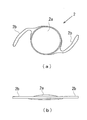
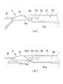
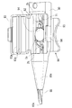
- FIG. 1 shows a schematic configuration of a conventional intraocular lens insertion device 1 (hereinafter also simply referred to as an insertion device 1).
- 1A is a plan view
- FIG. 1B is a side view.
- the insertion instrument 1 is formed in a cylindrical shape having a substantially rectangular cross section, and one side is greatly opened (hereinafter, the side that is largely opened is referred to as a rear end part 10b), and the insertion cylinder is narrowed to another one side end.
- the nozzle main body 10 as an instrument main body provided with the nozzle part 15 as a part and the front-end
- the direction from the front end 10a to the rear end 10b of the nozzle body 10 or the opposite direction is the front-rear direction
- the vertical direction to the paper surface in FIG. 1A is the vertical direction
- the paper surface in FIG. The vertical direction is the left-right direction.
- a stage portion 12 is provided as a storage portion for setting the intraocular lens 2.
- the stage 12 opens the stage lid 13 so that the upper side of the nozzle body 10 (the front side perpendicular to the paper surface in FIG. 1A and corresponding to the optical axis front side of the intraocular lens) is opened. It has come to be.
- a positioning member 50 is attached to the stage portion 12 from the lower side of the nozzle body 10 (the back side perpendicular to the paper surface in FIG. 1A and corresponds to the rear side of the optical axis of the intraocular lens). Yes.
- the intraocular lens 2 is stably held in the stage portion 12 before use (during transportation).
- the intraocular lens 2 is on the stage unit 12 and the front side of the optical axis is on the upper side in a state where the stage lid unit 13 is opened and the positioning member 50 is attached to the stage unit 12. Is set as Then, after the stage lid 13 is closed, it is shipped and sold. Further, during use, the user removes the positioning member 50 while keeping the stage lid 13 closed, and then pushes the plunger 30 into the distal end side of the nozzle body 10. As a result, the intraocular lens 2 is pressed by the plunger 30 and moved to the nozzle portion 15, and then the intraocular lens 2 is pushed out from the distal end portion 10 a.
- the nozzle body 10, the plunger 30, and the positioning member 50 in the insertion instrument 1 are formed of a resin material such as polypropylene. Polypropylene is a material with a proven track record in medical equipment and high reliability such as chemical resistance.
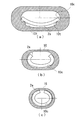
- FIG. 2 is a diagram showing a schematic configuration of the intraocular lens 2.
- 2A is a plan view and FIG. 2B is a side view.
- the intraocular lens 2 includes a lens body 2a having a predetermined refractive power, and two beard-shaped support portions 2b and 2b that are provided integrally with the lens body 2a and hold the lens body 2a inside the eyeball. Is formed.
- the lens body 2a and the support portion 2b are made of a flexible resin material.
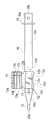
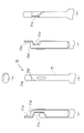
- FIG. 3 shows a plan view of the nozzle body 10.
- the intraocular lens 2 is set on the stage unit 12. In this state, the intraocular lens 2 is released from the distal end portion 10a by being pressed by the plunger 30.
- a through hole 10 c whose cross-sectional shape changes according to a change in the outer shape of the nozzle body 10 is provided in the nozzle body 10.
- the intraocular lens 2 is released, the intraocular lens 2 is deformed according to a change in the cross-sectional shape of the through hole 10c in the nozzle body 10 and easily enters an incision formed in the patient's eyeball. It will be released after being transformed into a shape.
- the distal end portion 10a is inclined so that the upper side is the front side from the lower side (the position of the end surface is the front side in the intraocular lens insertion direction as it goes from the rear side of the optical axis of the stored intraocular lens 2 to the front side). It has a shape that is cut. In addition, about the shape cut diagonally of this front-end
- a stage groove 12 a having a width slightly larger than the diameter of the lens body 2 a of the intraocular lens 2 is formed in the stage portion 12.
- the dimension in the front-rear direction of the stage groove 12 a is set to be larger than the maximum width dimension including the support portions 2 b and 2 b extending on both sides of the intraocular lens 2.
- a set surface 12b is formed by the bottom surface of the stage groove 12a.
- the vertical position of the set surface 12b (the position perpendicular to the paper surface of FIG. 3) is set higher than the height position of the bottom surface of the through hole 10c of the nozzle body 10 (the front side perpendicular to the paper surface of FIG. 3).
- the set surface 12b and the bottom surface of the through hole 10c are connected by a bottom slope 10d.
- the stage portion 12 and the stage lid portion 13 are integrally formed.
- the stage lid portion 13 has the same size in the front-rear direction as the stage portion 12.
- the stage lid portion 13 is connected by a thin plate-like connecting portion 14 formed by extending the side surface of the stage portion 12 to the stage lid portion 13 side.
- the connecting portion 14 is formed to be bendable at the center portion, and the stage lid portion 13 can be closed by overlapping the stage portion 12 from above by bending the connecting portion 14.
- ribs 13 a and 13 b are provided on the surface facing the set surface 12 b when the lid is closed in order to reinforce the stage lid 13 and stabilize the position of the intraocular lens 2.
- a guide protrusion 13 c is provided as a guide on the upper side of the plunger 30.
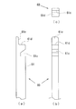
- FIG. 4 shows a schematic configuration of the positioning member 50.
- 4A shows a plan view
- FIG. 4B shows a side view.
- the positioning member 50 is configured as a separate body from the nozzle main body 10, and has a structure in which a pair of side wall portions 51, 51 are connected by a connecting portion 52. At the lower ends of the respective side wall portions 51, holding portions 53, 53 extending outward and extending are formed.
- first mounting portions 54 and 54 are formed on the upper end portions of the respective side wall portions 51 and 51 so that the shape seen from above is an arc shape and protrudes upward.
- first positioning portions 55, 55 are formed to protrude from the outer peripheral side of the upper end surface of the first placement portion 54. The distance between the inner diameters of the first positioning portion 55 is set to be slightly larger than the diameter dimension of the lens body 2 a of the intraocular lens 2.
- a pair of second placement portions 56 and 56 are formed at both ends of the connecting portion 52 in the front-rear direction, and the shape seen from above is a rectangular shape and protrudes upward.
- the height of the upper surface of the second placement unit 56 is equal to the height of the upper surface of the first placement unit 54.
- second positioning portions 57 and 57 are formed on the outer surface of the second placement portions 56 and 56 so as to further protrude upward over the entire left and right direction of the second placement portion 56. .
- the separation between the insides of the second positioning portions 57 is set to be slightly larger than the diameter of the lens body 2a of the intraocular lens 2.
- locking claws 58 and 58 that slightly protrude in the front-rear direction are formed on the upper end portion of the second placement portion 56 over the entire left-right direction.
- the positioning member 50 is assembled from below the set surface 12b of the nozzle body 10.
- the set surface 12b of the nozzle body 10 is formed with a set surface through hole 12c that penetrates the set surface 12b in the thickness direction.
- the outer shape of the set surface through-hole 12c is a substantially similar shape that is slightly larger than the shape of the first placement portion 54 and the second placement portion 56 of the positioning member 50 as viewed from above.
- the positioning member 50 is assembled from the lower side of the nozzle body 10, and the first placement portions 54 and 54 and the second placement portions 56 and 56 are fixed in a state of protruding from the set surface 12b.
- the bottom surface of the outer peripheral portion of the lens body 2a is placed on the upper surfaces of the first placement portions 54 and 54 and the second placement portions 56 and 56.
- the position of the lens body 2 a is restricted with respect to the horizontal direction by the first positioning portions 55 and 55 and the second positioning portions 57 and 57.
- FIG. 5 shows a schematic configuration of a conventional plunger 30.
- the plunger 30 has a length in the front-rear direction that is slightly larger than the nozzle body 10. And it forms from the action part 31 of the front end side based on a column shape, and the insertion part 32 of the rear end side based on a rectangular rod shape. And the action part 31 is comprised including the cylindrical part 31a made into the column shape, and the thin plate-shaped flat part 31b extended in the left-right direction of the cylindrical part 31a.
- a notch 31 c is formed at the tip of the action part 31.
- the notch 31 c is formed in a groove shape that opens upward in the action portion 31 and penetrates in the left-right direction.
- the groove wall on the distal end side of the cutout portion 31 c is formed with an inclined surface that goes upward as it goes to the distal end side of the action portion 31.
- the insertion portion 32 has a substantially H-shaped cross section as a whole, and the horizontal and vertical dimensions thereof are set slightly smaller than the through hole 10c of the nozzle body 10.
- a disc-shaped pressing plate portion 33 is formed at the rear end of the insertion portion 32 so as to spread in the vertical and horizontal directions.
- a claw portion 32 a that protrudes toward the upper side of the insertion portion 32 and can be moved up and down by the elasticity of the material of the plunger 30 is formed at the tip side of the insertion portion 32 in the front-rear direction center.
- the locking hole 10 e shown in FIG. 3 provided in the thickness direction on the upper surface of the nozzle body 10 and the claw portion 32 a engage with each other.
- the relative position between the nozzle body 10 and the plunger 30 in the state is determined.
- the claw portion 32a and the locking hole 10e are formed at the positions where the tip of the action portion 31 is located behind the lens body 2a of the intraocular lens 2 set on the stage portion 12 in the engaged state. It is set so that the notch 31c can support the support part 2b on the rear side of 2a from below.
- the plunger 30 is inserted into the nozzle body 10 and disposed at the initial position. Further, as described above, the positioning member 50 is attached to the nozzle body 10 from below the set surface 12b. Thereby, the 1st mounting part 54 and the 2nd mounting part 56 of the positioning member 50 are hold
- the lens body 2a of the intraocular lens 2 is placed and positioned on the upper surfaces of the first placement part 54 and the second placement part 56 in a state where the support parts 2b and 2b are oriented in the front-rear direction of the nozzle body 10.
- the central portion of the intraocular lens 2 is supported in an unloaded state.
- the support portion 2 b on the rear side of the intraocular lens 2 is supported by the bottom surface of the notch portion 31 c of the plunger 30.
- the positioning member 50 When inserting the intraocular lens 2 into the eyeball using the insertion instrument 1, first, the positioning member 50 is removed from the nozzle body 10. Thereby, the 1st mounting part 54 and the 2nd mounting part 56 which were supporting the lens main body 2a of the intraocular lens 2 retreat from the set surface 12b, and the intraocular lens 2 can move on the set surface 12b. Placed.
- the distal end portion 10a of the nozzle portion 15 of the nozzle body 10 is inserted into the incision provided in the eye tissue.
- the distal end portion 10a has an oblique opening shape, it can be easily inserted into the incision.
- the press board part 33 of the plunger 30 is pushed in the front end side of the nozzle main body 10 in the state.
- the opening shape of the tip portion 10a may be a flat, that is, linear, diagonal opening shape, or an oblique opening shape having a bulge on the outside, that is, a curved surface shape. It may be.
- the action portion is not necessarily used.
- the tip of 31 does not press the center of gravity of the lens body 2 a of the intraocular lens 2. Further, at the moment when the intraocular lens is released from the distal end portion 10a, only the upper side is held by the end portion of the distal end portion 10a, and the lower side is not held. Therefore, when the intraocular lens 2 is released from the distal end portion 10a of the nozzle unit 15, the intraocular lens 2 tends to rotate so as to rotate forward.
- the lens body 2a of the intraocular lens 2 is sandwiched between the through-hole 10c (inner wall of the nozzle body 10) near the distal end portion 10a and the action portion 31 of the plunger 30, so that the intraocular lens 2 is smoothly moved from the distal end portion 10a. In some cases, it was not released.
- the intraocular lens 2 is released more smoothly from the distal end portion 10a of the nozzle portion 15 while maintaining the posture by changing the distal end shape of the action portion of the plunger. did.
- FIG. 6 the shape of the vicinity of the front-end
- a protrusion 61e is provided as a protrusion on which the lens body 2a is placed below the tip 61d of the action portion 61 (on the rear side of the optical axis of the intraocular lens 2). It was.
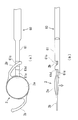
- FIG. 7 is a diagram for explaining the positional relationship between the plunger 60 and the intraocular lens 2 before and after operation in the present embodiment.
- FIG. 7A is a plan view in a state before the insertion work of the intraocular lens 2 is started
- FIG. 7B is a side view in the same state.
- the support portion 2b on the rear side of the intraocular lens 2 is supported from below by the notch 61c of the action portion 61 of the plunger 60.
- the state before starting the insertion operation of the intraocular lens 2 that is, the positioning member 50 is attached to the stage portion 12, and the locking hole 10e and the plunger 60 shown in FIG.
- the upper surface of the protrusion 61e is positioned below the lens body 2a of the intraocular lens 2, and the tip of the protrusion 61e slightly enters from the outer periphery of the lens body 2a toward the center. It is in a state.
- the position of the intraocular lens 2 is relatively lowered as shown by the arrow in FIG. And the outer peripheral part of the lens main body 2a of the intraocular lens 2 is mounted on the protrusion 61e.
- the plunger 60 moves forward (left side in FIG. 7) while the outer peripheral portion of the lens body 2a of the intraocular lens 2 is placed on the upper surface of the protrusion 61e.
- the tip 61d moves and comes into contact with the outer periphery of the lens body 2a from the horizontal direction.
- the tip 61d presses the outer peripheral portion of the lens body 2a to move the intraocular lens 2 to the nozzle portion 15 and releases it from the tip 10a.
- FIG. 8 is a diagram for explaining a state when the intraocular lens 2 is released from the tip portion 10a of the nozzle portion 15.
- FIG. 8A shows a case where extrusion is performed by the conventional plunger 30, and
- FIG. 8B shows a case where extrusion is performed by the plunger 60 in this embodiment.
- the intraocular lens 2 is deformed with a change in the cross-sectional shape of the through hole 10c, and the width dimension in the vertical direction is increased.
- the intraocular lens 2 when the intraocular lens 2 is released from the distal end portion 10a, the intraocular lens 2 is held on the lower side (the rear side of the optical axis of the lens body 2a). Therefore, the intraocular lens 2 tends to move forward in the direction of the arrow in the figure due to the moment due to its own weight. As a result, when the intraocular lens 2 is released into the eyeball, it is difficult to maintain the posture of the lens body 2a, and the posture of the intraocular lens 2 has to be re-adjusted after the release. .
- the lens body 2a is held so as to be sandwiched from above and below by the upper surface of the protrusion 61e and the upper inner wall of the through hole 10c. Therefore, in this embodiment, the intraocular lens 2 can be released while maintaining the posture in the pressing direction by the plunger 60 as shown in FIG.
- the lens body 2a of the intraocular lens 2 is sandwiched in the gap between the outer wall of the action part 31 of the plunger 30 and the through hole 10c, and is not released smoothly. There was a case.
- the lens main body 2a of the intraocular lens 2 is stably supported by the protrusion 61e and the tip 61d, so that the outer wall of the action portion 31 of the plunger 30 is Inconveniences such as being caught in the gap between the through holes 10c can be suppressed.
- the upper area of the distal end portion 10a of the nozzle body 15 corresponds to a “partial area” which is the front side in the insertion direction of the intraocular lens at the distal end of the insertion tube section.
- a protrusion 61e on which the lens body 2a is placed is provided below the distal end 61d of the action portion 61 (on the rear side of the optical axis of the intraocular lens 2). This is because one end of the intraocular lens is located on the tip of the plunger opposite to the “partial region” at the tip of the insertion tube portion when viewed from the front of the intraocular lens insertion direction when the intraocular lens is inserted.
- the cross-sectional shape of the through hole 10c in the present embodiment changes so that the width dimension of the bottom surface and the top surface becomes smaller from the stage portion 12 side to the nozzle portion 15 side. Due to this change, when the intraocular lens 2 is released from the distal end portion 10c, the intraocular lens 2 is deformed so as to surround the axis in the movement direction so as to be convex upward or convex downward. Thereby, the intraocular lens 2 can be inserted into the eyeball even from a small incision.
- the convex portion can be more securely held on the upper surface of the projection 61e when the intraocular lens 2 is deformed to be convex downward. it can. Even if the lens body 2a of the intraocular lens 2 is restored to its original shape immediately after the release, it is easier to maintain the holding state by the protrusion 61e if it is deformed so as to be convex downward. Therefore, in this embodiment, a mechanism that promotes deformation such that the intraocular lens 2 is convex downward is employed in the nozzle body 10 in accordance with the use of the plunger 60.
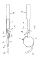
- FIG. 9 shows a cross-sectional view of the nozzle body 10 in the present embodiment.
- 9A is a cross-sectional view immediately after the intraocular lens 2 is pressed by the plunger 60 and starts moving
- FIG. 9B is a nozzle unit 15 from the stage unit 12 side as shown in FIG.
- FIG. 9C is a sectional view in the middle of the width dimension of the bottom surface and the top surface becoming smaller toward the side
- FIG. 9C shows a sectional view when the intraocular lens 2 passes through the nozzle portion 15.
- Each sectional view also shows the shape of the lens body 2a of the intraocular lens 2 when passing through the section.
- the through hole 10c before the cross-sectional shape is changed just before the stage portion 12 contacts the left and right outer peripheral portions of the lens body 2a from below.
- Guides 10t and 10t are formed.
- the guides 10t and 10t guide the left and right outer peripheral portions of the lens body 2a so as not to be displaced downward. Thereby, it can accelerate
- the guides 10t and 10t correspond to lens deformation means in this embodiment.
- the guides 10t and 10t provided in the through hole 10c of the nozzle body 10 are exemplified as the lens deformation means.
- the lens deformation means may have another configuration.
- the nozzle body 10 has a configuration in which the cross section of the nozzle body 10 is reduced by a two-step taper of a first taper portion that is gentle and a second taper portion that has a sharper taper than the first taper portion.
- the guide may be provided in a convex shape at the center on the upper side (front side of the lens optical axis) of the through hole 10c and on the lower side (back side of the lens optical axis).
- the action portion 61 has been described by taking the plunger 60 having a prismatic cross section as an example, but this is only an example, and the shape of the plunger including the action portion 61 is Of course, other shapes may be used without departing from the spirit of the present invention. The same applies to the shapes of the nozzle body and the nozzle portion.
- FIG. 10 is a view of the vicinity of the tip of the action portion 71 of the plunger 70 in the present embodiment.
- the difference between the present embodiment and the plunger 60 in the first embodiment is that, in the plunger 60 of the first embodiment, the notch 61c that supports the support portion 2b is located on the upper side (the optical axis of the intraocular lens 2) as in the conventional example.
- the cutout portion 71c in this embodiment is disposed on the lower side (the rear side of the optical axis of the intraocular lens 2), it is disposed on the front side.
- FIG. 10 (a) and 10 (c) are side views seen from the left and right directions
- FIG. 10 (b) is a plan view seen from the front side of the optical axis of the intraocular lens 2
- FIG. 10 (d) is the eye.
- FIG.10 (e) is a front view.
- the protrusion 71 e is provided at the tip 71 d of the action part 71
- the notch part 71 c that holds the support part 2 b of the intraocular lens 2 is the action part 71.
- FIG. 11 is a diagram for explaining the positional relationship between the plunger 70 and the intraocular lens 2 in the present embodiment.
- FIG. 11A is a side view in a state before the insertion work of the intraocular lens 2 is started
- FIG. 11B is a bottom view of the same state as viewed from below.
- the state before the insertion of the intraocular lens 2 is started that is, the positioning member 50 is attached to the stage portion 12 and shown in FIG.
- the upper surface of the protrusion 71e is positioned below the lens body 2a of the intraocular lens 2, and the tip of the protrusion 71e is the lens body 2a. It is in a state of slightly entering from the outer peripheral side toward the center.
- the support portion 2b on the rear side of the intraocular lens 2 is held so as to penetrate through the notch portion 71c provided on the lower side of the action portion 71 of the plunger 70.
- the position of the intraocular lens 2 is relatively lowered as shown by the arrow in FIG. And the outer peripheral part of the lens main body 2a of the intraocular lens 2 is mounted on the protrusion 71e. At that time, the support portion 2b on the rear side of the intraocular lens 2 moves in the cutout portion 71c so that the position thereof is lowered similarly to the lens body 2a.
- the plunger 70 moves forward (left side in FIG. 11) while the lens body 2a of the intraocular lens 2 is placed on the upper surface of the protrusion 71e, and the tip is moved. 71d contacts the outer periphery of the lens body 2a.
- the tip 71 d presses the outer peripheral portion of the lens body 2 a to move the intraocular lens 2 to the nozzle portion 15.
- the support portion 2b on the rear side of the intraocular lens 2 moves while being held in the cutout portion 71c so as not to be inadvertently deformed.
- the intraocular lens 2 when the plunger 70 is further pushed, the intraocular lens 2 reaches the distal end portion 10a of the nozzle portion 15.
- the intraocular lens 2 when the intraocular lens 2 is released from the distal end portion 10a, the upper side of the lens body 2a of the intraocular lens 2 is supported by the wall surface of the through hole 10c and the lower side is supported by the protrusion 71e. In this state, it is discharged straight forward.
- the action portion 71 of the plunger 70 protrudes from the tip portion 10a, and the notch portion 71c is also exposed to the outside from the tip portion 10a. If it does so, the support part 2b of the intraocular lens 2 currently hold
- the intraocular lens 2 when the configuration of the plunger 70 as in the present embodiment is adopted, when the intraocular lens 2 is set on the stage unit 12, it is desirable to set it from the lower side. This is because the intraocular lens 2 is placed on the upper side (front side of the optical axis) so that the notch 71c holds the support 2b while the support 2b of the intraocular lens 2 passes through the notch 71c that opens downward. This is because it is difficult to set the stage 12 on the stage 12 and hinders the simplification of work.
- the stage lid is provided on the lower side of the nozzle body (on the rear side of the optical axis of the intraocular lens 2), and the positioning member is on the upper side (intraocular lens 2). (Front side of the optical axis) and can be set from the lower side (rear side of the optical axis) when the intraocular lens 2 is set on the stage portion.
- FIG. 12 is a perspective view showing the vicinity of the stage portion 82 in the nozzle body 80 of the insertion tool in such a case, as seen from the oblique direction on the lower side (the rear side of the lens optical axis).
- the stage lid portion 83 is provided on the lower side of the nozzle body 80 (on the rear side of the optical axis of the intraocular lens). Accordingly, when the intraocular lens 2 is set on the stage portion 82, the nozzle body 80 is turned upside down so that the stage lid portion 83 is directed upward (opposite to the ground), and then the intraocular lens 2 is set. Set. In this state, the holding portion 93 of the positioning member 90 protrudes downward (in the ground direction).
- the intraocular lens 2 is set on the stage portion 83 of the nozzle body 80.
- the cutout portion 71c of the plunger 70 is open in the upward direction (the direction opposite to the ground)
- the support portion 2a on the rear side of the intraocular lens 2 can be easily held in the cutout portion 71c. it can.
- the stage lid portion 83 is closed, the positioning member 90 is removed, and the upper and lower sides of the nozzle body are returned to the original position, whereby the setting of the intraocular lens 2 to the stage portion 82 is completed.
- the detailed configuration and operation of the stage lid 83 and the positioning member 90 are different from those of the stage lid 13 and the positioning member 50 in the first embodiment.
- the positioning member 90 the position of the lens body 2a in the height direction is first described.
- the first mounting portion 94 that restricts the contact is in contact with the optical surface on the front side of the optical axis of the lens body 2a of the intraocular lens 2, but only in contact with the outside of the actual use region. It has a structure that does not.
- the point that the guide guide 83 a of the plunger 70 is provided on the inner wall surface of the stage lid portion 83 is also different from the first embodiment.
- the intraocular lens 2 when the intraocular lens 2 is released from the tip portions 10a and 80a of the nozzle portions 15 and 85, the intraocular lens 2 rotates in the forward rotation direction, Inconveniences such as being caught between the through holes 10c, 80c near the distal end portions 10a, 80a and the outer wall of the action portion 71 of the plunger 70 can be suppressed, and the intraocular lens 2 can be discharged into the eyeball more smoothly. Become.
- the notch 71c of the plunger 70 is provided on the lower side (the rear side of the optical axis of the intraocular lens 2), when the intraocular lens 2 is inserted into the eyeball, The support portion 2a can be detached from the plunger 70 more reliably, and the intraocular lens 2 can be released more securely in the eyeball. Further, since the elastic deformation and restoration operations of the support portion 2b can be suppressed, the influence on the position adjustment such as the posture change of the intraocular lens 2 can be suppressed.
- the one-piece type intraocular lens in which the lens body 2a of the intraocular lens 2 and the support portions 2b and 2b are integrally formed has been described as an example.
- the support portions 2b and 2b are used as the lens body.
- the present invention can also be applied to a three-piece intraocular lens formed of a member different from 2a.
- the distal end portion 10a has the upper surface on the front side from the lower side (the position of the end surface is more on the front side in the intraocular lens insertion direction as it goes from the rear side of the optical axis of the stored intraocular lens 2 to the front side). ), An example in which the shape is cut obliquely is shown. However, the present invention is not limited to such a configuration.
- the lower end of the tip of the nozzle portion is in front of the upper side (the end face is positioned in front of the insertion direction of the intraocular lens as it moves from the front side to the rear side of the stored intraocular lens 2).
- the lens body 2a is held so as to be sandwiched from above and below by the lower surface of the protrusion and the lower inner wall of the through hole 10c. This also allows the intraocular lens 2 to be released while maintaining the posture in the pressing direction by the plunger.
Abstract
Description
前記器具本体に一体または別体に設けられ眼内レンズを収納することで前記眼内レンズを前記器具本体の中に配置可能な収納部と、
前記器具本体に押し込まれて前記収納部に収納された前記眼内レンズを先端で押圧することで前記眼内レンズを前記挿入筒部の先端から眼球内に放出するプランジャと、
を備え、
前記切開創より眼球内に挿入された前記挿入筒部の先端から前記眼内レンズを眼球内に放出することで眼内レンズを眼球内に挿入する眼内レンズの挿入器具であって、
前記挿入筒部の先端は、その一部の領域が眼内レンズ挿入方向のより前側になるように斜めにカットされ、
前記プランジャの先端における、前記眼内レンズの挿入時に眼内レンズ挿入方向前側から見て前記挿入筒部の先端の前記領域の反対側となる部分には、前記眼内レンズの一部を載置可能なように眼内レンズ挿入方向のより前側に突出した突出部が設けられたことを特徴とする。 The present invention includes an instrument body having an insertion cylinder portion to be inserted into an incision formed in eyeball tissue and formed in a substantially cylindrical shape;
A storage unit that can be arranged in the instrument body by housing the intraocular lens integrally or separately in the instrument body;
A plunger that is pushed into the instrument body and presses the intraocular lens housed in the housing portion with a tip to release the intraocular lens into the eyeball from the tip of the insertion tube part;
With
An intraocular lens insertion device for inserting an intraocular lens into an eyeball by releasing the intraocular lens from the distal end of the insertion tube portion inserted into the eyeball from the incision,
The distal end of the insertion tube part is cut obliquely so that a part of the region is in front of the insertion direction of the intraocular lens,
A portion of the intraocular lens is placed on a portion of the distal end of the plunger that is opposite to the region at the distal end of the insertion tube portion when viewed from the front side in the intraocular lens insertion direction when the intraocular lens is inserted. The protrusion part which protruded in the front side of the intraocular lens insertion direction so that it was possible was provided.
前記突出部は、前記眼内レンズの挿入時に前記眼内レンズの光軸後側の面を載置可能なように設けられるようにしてもよい。 In the present invention, as the tip of the insertion tube portion moves from the rear side of the optical axis of the intraocular lens housed in the housing portion to the front side, the position of the end surface becomes the front side in the insertion direction of the intraocular lens. So that it is cut diagonally
The protrusion may be provided so that a surface on the rear side of the optical axis of the intraocular lens can be placed when the intraocular lens is inserted.
図1には、従来の眼内レンズの挿入器具1(以下、単に、挿入器具1ともいう。)の概略構成を示す。図1(a)は平面図、図1(b)は側面図を示している。挿入器具1は、断面略矩形の筒状に形成されており片側は大きく開口し(以下、大きく開口した側を後端部10bという。)、別の片側端部には細く絞られた挿入筒部としてのノズル部15及び斜めに開口した先端部10aを備える器具本体としてのノズル本体10と、ノズル本体10に挿入され往復運動可能なプランジャ30とを備えている。なお、以下において、ノズル本体10の先端部10aから後端部10bへ向かう方向またはその逆方向を前後方向、図1(a)において紙面に垂直方向を上下方向、図1(b)において紙面に垂直方向を左右方向とする。 <Example 1>
FIG. 1 shows a schematic configuration of a conventional intraocular lens insertion device 1 (hereinafter also simply referred to as an insertion device 1). 1A is a plan view, and FIG. 1B is a side view. The
次に、本発明の実施例2について説明する。実施例2においては、プランジャにおいて眼内レンズの後側の支持部を支持する切欠部が、プランジャの下側(眼内レンズの光軸後側)に設けられた例について説明する。 <Example 2>
Next, a second embodiment of the present invention will be described. In the second embodiment, an example will be described in which a notch for supporting the rear support portion of the intraocular lens in the plunger is provided on the lower side of the plunger (the optical axis rear side of the intraocular lens).
2・・・眼内レンズ
10、80・・・ノズル本体
10a、80a・・・先端部
10b・・・後端部
12、82・・・ステージ部
13、83・・・ステージ蓋部
15、85・・・挿入筒部
30、60、70・・・プランジャ
31、61、71・・・作用部
31a・・・円柱部
31b・・・扁平部
50、90・・・位置決め部材
61c、71c・・・切欠部
61d、71d・・・先端
61e、71e・・・突起 DESCRIPTION OF
Claims (4)
- 眼球組織に形成された切開創に挿入される挿入筒部を有し略筒状に形成された器具本体と、
前記器具本体に一体または別体に設けられ眼内レンズを収納することで前記眼内レンズを前記器具本体の中に配置可能な収納部と、
前記器具本体に押し込まれて前記収納部に収納された前記眼内レンズを先端で押圧することで前記眼内レンズを前記挿入筒部の先端から眼球内に放出するプランジャと、
を備え、
前記切開創より眼球内に挿入された前記挿入筒部の先端から前記眼内レンズを眼球内に放出することで眼内レンズを眼球内に挿入する眼内レンズの挿入器具であって、
前記挿入筒部の先端は、その一部の領域が眼内レンズ挿入方向のより前側になるように斜めにカットされ、
前記プランジャの先端における、前記眼内レンズの挿入時に眼内レンズ挿入方向前側から見て前記挿入筒部の先端の前記領域の反対側となる部分には、前記眼内レンズの一部を載置可能なように眼内レンズ挿入方向のより前側に突出した突出部が設けられたことを特徴とする眼内レンズの挿入器具。 An instrument body having an insertion tube portion to be inserted into an incision formed in the eyeball tissue and formed in a substantially cylindrical shape;
A storage unit that can be arranged in the instrument body by housing the intraocular lens integrally or separately in the instrument body;
A plunger that is pushed into the instrument body and presses the intraocular lens housed in the housing portion with a tip to release the intraocular lens into the eyeball from the tip of the insertion tube part;
With
An intraocular lens insertion device for inserting an intraocular lens into an eyeball by releasing the intraocular lens from the distal end of the insertion tube portion inserted into the eyeball from the incision,
The distal end of the insertion tube part is cut obliquely so that a part of the region is in front of the insertion direction of the intraocular lens,
A portion of the intraocular lens is placed on a portion of the distal end of the plunger that is opposite to the region at the distal end of the insertion tube portion when viewed from the front side in the intraocular lens insertion direction when the intraocular lens is inserted. An insertion device for an intraocular lens, characterized in that a protrusion is provided so as to protrude further forward in the intraocular lens insertion direction. - 前記挿入筒部の先端は、前記収納部に収納された眼内レンズの光軸後側から前側にいくに従って、端面の位置が眼内レンズ挿入方向のより前側になるように斜めにカットされ、
前記突出部は、前記眼内レンズの挿入時に前記眼内レンズの光軸後側の面を載置可能なように設けられたことを特徴とする請求項1に記載の眼内レンズの挿入器具。 The distal end of the insertion tube part is cut obliquely so that the position of the end face is more forward in the intraocular lens insertion direction as it goes from the rear side of the optical axis of the intraocular lens housed in the housing part to the front side,
2. The intraocular lens insertion device according to claim 1, wherein the protrusion is provided so that a surface on the rear side of the optical axis of the intraocular lens can be placed when the intraocular lens is inserted. . - 前記プランジャによって前記収納部に収納された前記眼内レンズを押圧することで前記眼内レンズを前記挿入筒部の先端から眼球内に放出する際に、前記眼内レンズを光軸後側に凸になるように変形させるレンズ変形手段をさらに備えることを特徴とする請求項2に記載の眼内レンズの挿入器具。 When the intraocular lens is released from the distal end of the insertion tube part into the eyeball by pressing the intraocular lens housed in the housing part by the plunger, the intraocular lens is projected backward on the optical axis. The intraocular lens insertion device according to claim 2, further comprising lens deforming means for deforming to become.
- 前記眼内レンズの挿入器具は、製造工程で予め眼内レンズが前記収納部に収納され、該眼内レンズが収納された状態で流通する、プリセット型挿入器具であることを特徴とする請求項1から3のいずれか一項に記載の眼内レンズの挿入器具。 The intraocular lens insertion device is a preset type insertion device in which an intraocular lens is stored in the storage unit in advance in a manufacturing process and distributed in a state in which the intraocular lens is stored. The intraocular lens insertion device according to any one of 1 to 3.
Priority Applications (6)
| Application Number | Priority Date | Filing Date | Title |
|---|---|---|---|
| KR1020157015487A KR102202985B1 (en) | 2012-11-29 | 2013-11-29 | Intraocular lens insertion device |
| CN201380062526.6A CN104812337B (en) | 2012-11-29 | 2013-11-29 | Intraocular lens insertion apparatus |
| JP2014549920A JP6258865B2 (en) | 2012-11-29 | 2013-11-29 | Intraocular lens insertion device |
| EP13858851.2A EP2926770B1 (en) | 2012-11-29 | 2013-11-29 | Intraocular lens insertion device |
| US14/648,119 US9855138B2 (en) | 2012-11-29 | 2013-11-29 | Intraocular lens insertion device |
| HK16100255.2A HK1212196A1 (en) | 2012-11-29 | 2016-01-12 | Intraocular lens insertion device |
Applications Claiming Priority (2)
| Application Number | Priority Date | Filing Date | Title |
|---|---|---|---|
| JP2012-260423 | 2012-11-29 | ||
| JP2012260423 | 2012-11-29 |
Publications (1)
| Publication Number | Publication Date |
|---|---|
| WO2014084355A1 true WO2014084355A1 (en) | 2014-06-05 |
Family
ID=50827983
Family Applications (1)
| Application Number | Title | Priority Date | Filing Date |
|---|---|---|---|
| PCT/JP2013/082183 WO2014084355A1 (en) | 2012-11-29 | 2013-11-29 | Intraocular lens insertion device |
Country Status (7)
| Country | Link |
|---|---|
| US (1) | US9855138B2 (en) |
| EP (1) | EP2926770B1 (en) |
| JP (1) | JP6258865B2 (en) |
| KR (1) | KR102202985B1 (en) |
| CN (1) | CN104812337B (en) |
| HK (1) | HK1212196A1 (en) |
| WO (1) | WO2014084355A1 (en) |
Cited By (8)
| Publication number | Priority date | Publication date | Assignee | Title |
|---|---|---|---|---|
| JP2015157051A (en) * | 2014-02-25 | 2015-09-03 | 株式会社ニデック | Intraocular lens insertion instrument and intraocular lens insertion system |
| US9463089B2 (en) | 2012-05-21 | 2016-10-11 | Novartis Ag | Plunger system for intraocular lens surgery |
| CN107072780A (en) * | 2014-11-19 | 2017-08-18 | 兴和株式会社 | Intraocular lens inserts equipment |
| US9757536B2 (en) | 2012-07-17 | 2017-09-12 | Novartis Ag | Soft tip cannula |
| US10568735B2 (en) | 2017-01-13 | 2020-02-25 | Alcon Inc. | Intraocular lens injector |
| US10588780B2 (en) | 2015-03-04 | 2020-03-17 | Alcon Inc. | Intraocular lens injector |
| US11000367B2 (en) | 2017-01-13 | 2021-05-11 | Alcon Inc. | Intraocular lens injector |
| JP6943519B1 (en) * | 2021-05-28 | 2021-10-06 | 株式会社中京メディカル | Intraocular lens mounting device |
Families Citing this family (3)
| Publication number | Priority date | Publication date | Assignee | Title |
|---|---|---|---|---|
| JP6511065B2 (en) * | 2013-11-15 | 2019-05-15 | メディセル・アーゲー | Device for receiving an intraocular lens and method of folding an intraocular lens |
| KR102445286B1 (en) * | 2016-07-07 | 2022-09-19 | 이올루션 게엠베하 | Cartridges for injectors that implant intraocular lenses |
| JP2022549948A (en) * | 2019-09-30 | 2022-11-29 | アルコン インコーポレイティド | soft tip plunger |
Citations (9)
| Publication number | Priority date | Publication date | Assignee | Title |
|---|---|---|---|---|
| JPH0824282A (en) | 1994-07-18 | 1996-01-30 | Canon Star Kk | Insertion apparatus for deformable intraocular implant |
| WO1999062436A1 (en) * | 1998-06-02 | 1999-12-09 | Alcon Laboratories, Inc. | Improved plunger |
| US20070173860A1 (en) * | 2006-01-20 | 2007-07-26 | Takuya Iwasaki | Plunger |
| CN101073518A (en) * | 2006-05-17 | 2007-11-21 | 佳能星股份有限公司 | Insertion device for intraocular lens |
| JP2008012016A (en) * | 2006-07-05 | 2008-01-24 | Hoya Corp | Intraocular lens insertion appliance |
| JP2009028223A (en) | 2007-07-26 | 2009-02-12 | Hoya Corp | Intraocular lens inserting instrument |
| EP2343029A1 (en) * | 2010-01-09 | 2011-07-13 | Nidek Co., Ltd. | Intraocular lens injection instrument |
| JP2012050713A (en) * | 2010-09-01 | 2012-03-15 | Nidek Co Ltd | Intraocular lens injection instrument |
| WO2012086797A1 (en) * | 2010-12-22 | 2012-06-28 | 興和株式会社 | Intraocular lens-inserting instrument |
Family Cites Families (12)
| Publication number | Priority date | Publication date | Assignee | Title |
|---|---|---|---|---|
| US5616148A (en) * | 1992-09-30 | 1997-04-01 | Staar Surgical Company, Inc. | Transverse hinged deformable intraocular lens injecting apparatus |
| US8460311B2 (en) * | 2004-12-27 | 2013-06-11 | Hoya Corporation | Intraocular lens implanting device |
| JPWO2007080869A1 (en) * | 2006-01-13 | 2009-06-11 | Hoya株式会社 | Intraocular lens insertion device |
| ATE474526T1 (en) | 2006-05-18 | 2010-08-15 | Staar Japan Inc | INTRAOCULAR LENS INSERTION DEVICE |
| JP5236638B2 (en) * | 2007-05-30 | 2013-07-17 | Hoya株式会社 | Intraocular lens insertion device |
| JP5086713B2 (en) * | 2007-07-11 | 2012-11-28 | Hoya株式会社 | Intraocular lens insertion device |
| JP5323334B2 (en) | 2007-09-14 | 2013-10-23 | スター・ジャパン株式会社 | Intraocular insertion lens insertion device and intraocular insertion lens insertion device |
| JP5123634B2 (en) | 2007-10-11 | 2013-01-23 | スター・ジャパン株式会社 | Intraocular insertion lens insertion device and intraocular insertion lens insertion device |
| JP5260956B2 (en) | 2007-12-27 | 2013-08-14 | スター・ジャパン株式会社 | Intraocular insertion lens insertion device and intraocular insertion lens insertion device |
| ES2549727T3 (en) | 2009-10-22 | 2015-11-02 | Kowa Company Ltd. | Intraocular lens insertion device |
| JP2012055394A (en) * | 2010-09-07 | 2012-03-22 | Nidek Co Ltd | Intraocular lens and intraocular lens insertion system |
| JP5697962B2 (en) | 2010-12-14 | 2015-04-08 | 興和株式会社 | Intraocular lens insertion device |
-
2013
- 2013-11-29 WO PCT/JP2013/082183 patent/WO2014084355A1/en active Application Filing
- 2013-11-29 CN CN201380062526.6A patent/CN104812337B/en active Active
- 2013-11-29 JP JP2014549920A patent/JP6258865B2/en active Active
- 2013-11-29 EP EP13858851.2A patent/EP2926770B1/en active Active
- 2013-11-29 US US14/648,119 patent/US9855138B2/en active Active
- 2013-11-29 KR KR1020157015487A patent/KR102202985B1/en active IP Right Grant
-
2016
- 2016-01-12 HK HK16100255.2A patent/HK1212196A1/en unknown
Patent Citations (22)
| Publication number | Priority date | Publication date | Assignee | Title |
|---|---|---|---|---|
| JPH0824282A (en) | 1994-07-18 | 1996-01-30 | Canon Star Kk | Insertion apparatus for deformable intraocular implant |
| WO1999062436A1 (en) * | 1998-06-02 | 1999-12-09 | Alcon Laboratories, Inc. | Improved plunger |
| CA2299462A1 (en) * | 1998-06-02 | 1999-12-09 | Alcon Laboratories, Inc. | Improved plunger |
| AU3753199A (en) * | 1998-06-02 | 1999-12-20 | Alcon Laboratories, Inc. | Improved plunger |
| US6010510A (en) * | 1998-06-02 | 2000-01-04 | Alcon Laboratories, Inc. | Plunger |
| EP0980230A1 (en) * | 1998-06-02 | 2000-02-23 | Alcon Laboratories, Inc. | Improved plunger |
| AU730447B2 (en) * | 1998-06-02 | 2001-03-08 | Alcon Laboratories, Inc. | Improved plunger |
| ATE211375T1 (en) * | 1998-06-02 | 2002-01-15 | Alcon Lab Inc | IMPROVED PISTON |
| DE69900737D1 (en) * | 1998-06-02 | 2002-02-28 | Alcon Lab Inc | IMPROVED PISTON |
| JP2002516709A (en) * | 1998-06-02 | 2002-06-11 | アルコン ラボラトリーズ,インコーポレイティド | Improved plunger |
| DE69900737T2 (en) * | 1998-06-02 | 2002-11-14 | Alcon Lab Inc | IMPROVED PISTON |
| US20070173860A1 (en) * | 2006-01-20 | 2007-07-26 | Takuya Iwasaki | Plunger |
| WO2007087104A1 (en) * | 2006-01-20 | 2007-08-02 | Alcon Manufacturing Ltd. | Improved plunger tip |
| CN101073518A (en) * | 2006-05-17 | 2007-11-21 | 佳能星股份有限公司 | Insertion device for intraocular lens |
| EP1857075A1 (en) * | 2006-05-17 | 2007-11-21 | Canon-Staar Co., Inc. | Insertion device for intraocular lens |
| US20070270881A1 (en) * | 2006-05-17 | 2007-11-22 | Hishinuma Yasuhiro | Insertion device for intraocular lens |
| JP2007307082A (en) * | 2006-05-17 | 2007-11-29 | Canon Star Kk | Intraocular lens insertion apparatus |
| JP2008012016A (en) * | 2006-07-05 | 2008-01-24 | Hoya Corp | Intraocular lens insertion appliance |
| JP2009028223A (en) | 2007-07-26 | 2009-02-12 | Hoya Corp | Intraocular lens inserting instrument |
| EP2343029A1 (en) * | 2010-01-09 | 2011-07-13 | Nidek Co., Ltd. | Intraocular lens injection instrument |
| JP2012050713A (en) * | 2010-09-01 | 2012-03-15 | Nidek Co Ltd | Intraocular lens injection instrument |
| WO2012086797A1 (en) * | 2010-12-22 | 2012-06-28 | 興和株式会社 | Intraocular lens-inserting instrument |
Non-Patent Citations (1)
| Title |
|---|
| See also references of EP2926770A4 |
Cited By (10)
| Publication number | Priority date | Publication date | Assignee | Title |
|---|---|---|---|---|
| US9463089B2 (en) | 2012-05-21 | 2016-10-11 | Novartis Ag | Plunger system for intraocular lens surgery |
| US9757536B2 (en) | 2012-07-17 | 2017-09-12 | Novartis Ag | Soft tip cannula |
| JP2015157051A (en) * | 2014-02-25 | 2015-09-03 | 株式会社ニデック | Intraocular lens insertion instrument and intraocular lens insertion system |
| CN107072780A (en) * | 2014-11-19 | 2017-08-18 | 兴和株式会社 | Intraocular lens inserts equipment |
| CN107072780B (en) * | 2014-11-19 | 2019-01-08 | 兴和株式会社 | Intraocular lens is inserted into equipment |
| US10507099B2 (en) | 2014-11-19 | 2019-12-17 | Kowa Company, Ltd. | Intraocular lens insertion apparatus |
| US10588780B2 (en) | 2015-03-04 | 2020-03-17 | Alcon Inc. | Intraocular lens injector |
| US10568735B2 (en) | 2017-01-13 | 2020-02-25 | Alcon Inc. | Intraocular lens injector |
| US11000367B2 (en) | 2017-01-13 | 2021-05-11 | Alcon Inc. | Intraocular lens injector |
| JP6943519B1 (en) * | 2021-05-28 | 2021-10-06 | 株式会社中京メディカル | Intraocular lens mounting device |
Also Published As
| Publication number | Publication date |
|---|---|
| CN104812337B (en) | 2018-03-16 |
| CN104812337A (en) | 2015-07-29 |
| KR102202985B1 (en) | 2021-01-13 |
| US9855138B2 (en) | 2018-01-02 |
| KR20150090898A (en) | 2015-08-06 |
| EP2926770B1 (en) | 2024-01-03 |
| HK1212196A1 (en) | 2016-06-10 |
| EP2926770A4 (en) | 2016-06-15 |
| US20150313709A1 (en) | 2015-11-05 |
| EP2926770A1 (en) | 2015-10-07 |
| JPWO2014084355A1 (en) | 2017-01-05 |
| JP6258865B2 (en) | 2018-01-10 |
Similar Documents
| Publication | Publication Date | Title |
|---|---|---|
| JP6258865B2 (en) | Intraocular lens insertion device | |
| WO2015012312A1 (en) | Intraocular lens-inserting instrument | |
| JP6099628B2 (en) | Intraocular lens insertion device | |
| JP5697962B2 (en) | Intraocular lens insertion device | |
| JP5189356B2 (en) | Intraocular lens insertion device | |
| JP6254080B2 (en) | Intraocular lens insertion device and positioning member provided in the intraocular lens insertion device | |
| WO2016195095A1 (en) | Intraocular lens insertion tool | |
| WO2012081419A1 (en) | Intraocular lens insertion apparatus | |
| JP2013244186A (en) | Intraocular lens insertion instrument | |
| JP6057749B2 (en) | Intraocular lens insertion device | |
| JP6614615B2 (en) | Intraocular lens insertion device | |
| JP2006068441A (en) | Intraocular lens insertion apparatus | |
| WO2013038688A1 (en) | Intraocular lens insertion tool | |
| JP6627267B2 (en) | Intraocular lens insertion device | |
| JP6524588B2 (en) | Intraocular lens insertion device | |
| JP2008043471A (en) | Intraocular lens inserting instrument | |
| CN111050698A (en) | Intraocular lens insertion device | |
| JP2018198747A (en) | Intraocular lens and intraocular lens insertion instrument | |
| JP5096132B2 (en) | Intraocular lens insertion device | |
| JP6601945B2 (en) | Intraocular lens insertion device | |
| WO2016017772A1 (en) | Intraocular lens insertion instrument | |
| WO2017030139A1 (en) | Intraocular lens inserting instrument |
Legal Events
| Date | Code | Title | Description |
|---|---|---|---|
| 121 | Ep: the epo has been informed by wipo that ep was designated in this application |
Ref document number: 13858851 Country of ref document: EP Kind code of ref document: A1 |
|
| ENP | Entry into the national phase |
Ref document number: 2014549920 Country of ref document: JP Kind code of ref document: A |
|
| WWE | Wipo information: entry into national phase |
Ref document number: 2013858851 Country of ref document: EP |
|
| WWE | Wipo information: entry into national phase |
Ref document number: 14648119 Country of ref document: US |
|
| NENP | Non-entry into the national phase |
Ref country code: DE |
|
| ENP | Entry into the national phase |
Ref document number: 20157015487 Country of ref document: KR Kind code of ref document: A |