JP5114489B2 - Sample analysis system, reagent preparation device, and sample processing device - Google Patents
Sample analysis system, reagent preparation device, and sample processing device Download PDFInfo
- Publication number
- JP5114489B2 JP5114489B2 JP2009531204A JP2009531204A JP5114489B2 JP 5114489 B2 JP5114489 B2 JP 5114489B2 JP 2009531204 A JP2009531204 A JP 2009531204A JP 2009531204 A JP2009531204 A JP 2009531204A JP 5114489 B2 JP5114489 B2 JP 5114489B2
- Authority
- JP
- Japan
- Prior art keywords
- reagent
- unit
- preparation
- water
- state
- Prior art date
- Legal status (The legal status is an assumption and is not a legal conclusion. Google has not performed a legal analysis and makes no representation as to the accuracy of the status listed.)
- Active
Links
- 239000003153 chemical reaction reagent Substances 0.000 title claims description 483
- 238000002360 preparation method Methods 0.000 title claims description 266
- 238000012545 processing Methods 0.000 title claims description 114
- 238000004458 analytical method Methods 0.000 title claims description 23
- 239000007788 liquid Substances 0.000 claims description 74
- 238000005259 measurement Methods 0.000 claims description 60
- 238000012423 maintenance Methods 0.000 claims description 49
- 238000001514 detection method Methods 0.000 claims description 31
- 238000010790 dilution Methods 0.000 claims description 21
- 239000012895 dilution Substances 0.000 claims description 21
- 230000005540 biological transmission Effects 0.000 claims description 16
- 238000007865 diluting Methods 0.000 claims description 15
- 239000008399 tap water Substances 0.000 claims description 12
- 235000020679 tap water Nutrition 0.000 claims description 12
- 238000004140 cleaning Methods 0.000 claims description 2
- 238000000746 purification Methods 0.000 claims 4
- XLYOFNOQVPJJNP-UHFFFAOYSA-N water Substances O XLYOFNOQVPJJNP-UHFFFAOYSA-N 0.000 description 213
- 238000001223 reverse osmosis Methods 0.000 description 211
- 239000000523 sample Substances 0.000 description 57
- 210000004369 blood Anatomy 0.000 description 48
- 239000008280 blood Substances 0.000 description 48
- 238000003860 storage Methods 0.000 description 30
- 238000000034 method Methods 0.000 description 26
- 239000012528 membrane Substances 0.000 description 19
- 238000004891 communication Methods 0.000 description 17
- 230000006870 function Effects 0.000 description 13
- 238000003756 stirring Methods 0.000 description 13
- 210000004027 cell Anatomy 0.000 description 12
- 238000004590 computer program Methods 0.000 description 12
- 238000004519 manufacturing process Methods 0.000 description 9
- 210000001772 blood platelet Anatomy 0.000 description 7
- 210000000265 leukocyte Anatomy 0.000 description 7
- 210000001995 reticulocyte Anatomy 0.000 description 7
- 210000000601 blood cell Anatomy 0.000 description 6
- 238000010586 diagram Methods 0.000 description 5
- 238000002156 mixing Methods 0.000 description 5
- 239000002245 particle Substances 0.000 description 5
- 238000005070 sampling Methods 0.000 description 5
- 238000004364 calculation method Methods 0.000 description 4
- 238000006243 chemical reaction Methods 0.000 description 4
- 238000004159 blood analysis Methods 0.000 description 3
- 230000001276 controlling effect Effects 0.000 description 3
- 238000002474 experimental method Methods 0.000 description 3
- 239000012535 impurity Substances 0.000 description 3
- 238000003825 pressing Methods 0.000 description 3
- 239000012470 diluted sample Substances 0.000 description 2
- 238000000684 flow cytometry Methods 0.000 description 2
- 230000007257 malfunction Effects 0.000 description 2
- 230000003287 optical effect Effects 0.000 description 2
- 239000012466 permeate Substances 0.000 description 2
- 230000000704 physical effect Effects 0.000 description 2
- 238000013459 approach Methods 0.000 description 1
- 239000012472 biological sample Substances 0.000 description 1
- 238000009534 blood test Methods 0.000 description 1
- 238000012937 correction Methods 0.000 description 1
- 230000002596 correlated effect Effects 0.000 description 1
- 230000000875 corresponding effect Effects 0.000 description 1
- 230000007547 defect Effects 0.000 description 1
- 238000007599 discharging Methods 0.000 description 1
- 230000000694 effects Effects 0.000 description 1
- 210000003743 erythrocyte Anatomy 0.000 description 1
- 239000000203 mixture Substances 0.000 description 1
- 238000012986 modification Methods 0.000 description 1
- 230000004048 modification Effects 0.000 description 1
- 238000011002 quantification Methods 0.000 description 1
- 235000002020 sage Nutrition 0.000 description 1
- 239000000243 solution Substances 0.000 description 1
- 238000010186 staining Methods 0.000 description 1
- 239000012192 staining solution Substances 0.000 description 1
- 239000008400 supply water Substances 0.000 description 1
Images


Classifications
-
- G—PHYSICS
- G01—MEASURING; TESTING
- G01N—INVESTIGATING OR ANALYSING MATERIALS BY DETERMINING THEIR CHEMICAL OR PHYSICAL PROPERTIES
- G01N35/00—Automatic analysis not limited to methods or materials provided for in any single one of groups G01N1/00 - G01N33/00; Handling materials therefor
- G01N35/00584—Control arrangements for automatic analysers
- G01N35/00594—Quality control, including calibration or testing of components of the analyser
- G01N35/00613—Quality control
- G01N35/00663—Quality control of consumables
- G01N2035/00673—Quality control of consumables of reagents
-
- Y—GENERAL TAGGING OF NEW TECHNOLOGICAL DEVELOPMENTS; GENERAL TAGGING OF CROSS-SECTIONAL TECHNOLOGIES SPANNING OVER SEVERAL SECTIONS OF THE IPC; TECHNICAL SUBJECTS COVERED BY FORMER USPC CROSS-REFERENCE ART COLLECTIONS [XRACs] AND DIGESTS
- Y10—TECHNICAL SUBJECTS COVERED BY FORMER USPC
- Y10T—TECHNICAL SUBJECTS COVERED BY FORMER US CLASSIFICATION
- Y10T436/00—Chemistry: analytical and immunological testing
- Y10T436/25—Chemistry: analytical and immunological testing including sample preparation
- Y10T436/25625—Dilution
Landscapes
- Engineering & Computer Science (AREA)
- Quality & Reliability (AREA)
- General Health & Medical Sciences (AREA)
- General Physics & Mathematics (AREA)
- Life Sciences & Earth Sciences (AREA)
- Chemical & Material Sciences (AREA)
- Analytical Chemistry (AREA)
- Biochemistry (AREA)
- Physics & Mathematics (AREA)
- Health & Medical Sciences (AREA)
- Immunology (AREA)
- Pathology (AREA)
- Automatic Analysis And Handling Materials Therefor (AREA)
- Feeding, Discharge, Calcimining, Fusing, And Gas-Generation Devices (AREA)
- Accessories For Mixers (AREA)
- Investigating Or Analysing Biological Materials (AREA)
- Sampling And Sample Adjustment (AREA)
Description
本発明は、検体分析システム、試薬調製装置および検体処理装置に関し、特に、高濃度試薬を希釈用液体を用いて希釈することにより試薬を調製する検体分析システム、試薬調製装置および検体処理装置に関する。 The present invention relates to a sample analysis system, a reagent preparation device, and a sample processing device, and more particularly to a sample analysis system, a reagent preparation device, and a sample processing device that prepare a reagent by diluting a high concentration reagent with a diluting liquid.
従来、高濃度試薬を希釈用液体を用いて希釈することにより試薬を調製する試薬調製装置が知られている。このような試薬調製装置は、たとえば、特開平9−33538号公報に開示されている。 Conventionally, a reagent preparation device for preparing a reagent by diluting a high concentration reagent with a diluting liquid is known. Such a reagent preparation apparatus is disclosed in, for example, Japanese Patent Laid-Open No. 9-33538.
上記特開平9−33538号公報には、高濃度試薬と純水(希釈用液体)とを収容するための調製タンクと、所定量の高濃度試薬を調製タンクに供給する試薬定量タンクと、純水を定量して調製タンクに供給する純水定量タンクと、純水を動作回数に応じて微量ずつ調製タンクへ補充することが可能なダイヤフラムポンプと、調製タンク内の希釈された試薬の電気伝導度を検出するセンサ(検出部)と、ダイヤフラムポンプの動作を制御する制御部とを備えた試薬調製装置が開示されている。この試薬調製装置は、一段階で高濃度試薬を所望の濃度に調製するのではなく、まず、調製タンクで高濃度試薬を高めの濃度に調製する。次に、試薬調製装置は、試薬の電気伝導度が試薬の濃度と相関することを利用して、調製タンク内の試薬の電気伝導度を監視しながら、ダイヤフラムポンプにより純水を調製タンクに微量投入する。これにより、調製タンク内の試薬が所望の濃度に近づけられる。なお、この試薬調製装置においては、純水を微量投入する際のダイヤフラムポンプの動作回数が、ダイヤフラムポンプが1回動作することによって変動する調製タンク内の試薬の電気伝導度の値(以下、「電気伝導度の変動値」ともいう)を用いて算出されている。 JP-A-9-33538 discloses a preparation tank for storing a high concentration reagent and pure water (dilution liquid), a reagent quantitative tank for supplying a predetermined amount of high concentration reagent to the preparation tank, A pure water metering tank that quantifies water and supplies it to the preparation tank, a diaphragm pump that can replenish pure water to the preparation tank in small amounts according to the number of operations, and the electrical conductivity of the diluted reagent in the preparation tank A reagent preparation device including a sensor (detection unit) for detecting the degree and a control unit for controlling the operation of the diaphragm pump is disclosed. This reagent preparation device does not prepare a high concentration reagent at a desired concentration in one step, but first prepares a high concentration reagent in a preparation tank to a higher concentration. Next, the reagent preparation device utilizes the fact that the electrical conductivity of the reagent correlates with the concentration of the reagent, and monitors the electrical conductivity of the reagent in the preparation tank, while using the diaphragm pump to add a small amount of pure water to the preparation tank. throw into. This brings the reagent in the preparation tank closer to the desired concentration. In this reagent preparation device, the number of operations of the diaphragm pump when a minute amount of pure water is added varies depending on the operation of the diaphragm pump once, and the value of the electrical conductivity of the reagent in the preparation tank (hereinafter, “ It is also calculated using “variable value of electric conductivity”.
しかしながら、上記特開平9−33538号公報の試薬調製装置で用いられる上述の電気伝導度の変動値は、予め実験により求められている。そのため、実験時に用いられた希釈用液体と物性の異なる希釈用液体を用いて高濃度試薬を希釈する場合には、上述の電気伝導度の変動値を用いてダイヤフラムポンプの動作回数を算出してしまうと、高濃度試薬を所望の濃度に希釈することができない場合がある。 However, the above-described fluctuation value of the electrical conductivity used in the reagent preparation apparatus disclosed in Japanese Patent Application Laid-Open No. 9-33538 is obtained in advance by experiments. Therefore, when diluting a high-concentration reagent using a diluting liquid that has different physical properties from the diluting liquid used during the experiment, the number of diaphragm pump operations is calculated using the above-mentioned fluctuation value of electrical conductivity. As a result, the high concentration reagent may not be diluted to a desired concentration.
この発明は、上記のような課題を解決するためになされたものであり、この発明の1つの目的は、希釈用液体の物性が変動する場合にも、高濃度試薬を所望の濃度に希釈するための目安となる目標値を決定することのできる試薬調製装置および検体処理装置を提供することである。 The present invention has been made to solve the above problems, and one object of the present invention is to dilute a high-concentration reagent to a desired concentration even when the physical properties of the dilution liquid fluctuate. It is an object to provide a reagent preparation device and a sample processing device that can determine a target value that serves as a guideline.
この発明のもう1つの目的は、試薬調製部(試薬調製装置)の状況を視覚を通じて容易に認識することが可能な検体分析システムおよび試薬調製装置を提供することである。 Another object of the present invention is to provide a sample analysis system and a reagent preparation device that can easily recognize the state of a reagent preparation unit (reagent preparation device) through vision.
上記目的を達成するために、この発明の第1の局面における検体分析システムは、高濃度試薬を希釈用液体を用いて希釈することにより、検体測定に用いられる試薬を調製する試薬調製部と、試薬調製部と接続され、試薬調製部により調製された試薬を用いて検体を測定する測定部とを備え、試薬調製部は、試薬調製部の状態および試薬調製部による試薬調製の状態の少なくとも一方を検出する状態検出部と、状態検出部により検出された状態情報を試薬調製部の外部のコンピュータに送信する送信部とを含み、コンピュータは、ディスプレイを含み、試薬調製部の送信部により送信された状態情報を受信し、受信した状態情報をディスプレイに表示するように構成され、試薬調製部の状態検出部は、高濃度試薬が試薬調製部に供給されない高濃度試薬供給不能状態を検出し、試薬調製部の送信部は、高濃度試薬供給不能状態を示す情報をコンピュータに送信し、コンピュータは、高濃度試薬供給不能状態を示すメッセージと、高濃度試薬の交換を促すメッセージと、交換後の高濃度試薬を用いて行う試薬の調製指示を受け付ける調製指示受付画面とを表示するとともに、調製指示受付画面によって調製指示が受け付けられると、受け付けた調製指示に基づく調製指示情報を試薬調製部に送信し、試薬調製部は、コンピュータにより送信された調製指示情報を受信し、交換後の高濃度試薬を用いて行う試薬の調製を実行するように構成されている。 In order to achieve the above object, a sample analysis system according to the first aspect of the present invention includes a reagent preparation unit that prepares a reagent used for sample measurement by diluting a high-concentration reagent with a dilution liquid; A measuring unit that is connected to the reagent preparing unit and measures a sample using the reagent prepared by the reagent preparing unit, and the reagent preparing unit includes at least one of a state of the reagent preparing unit and a state of reagent preparing by the reagent preparing unit. A state detection unit that detects the state and a transmission unit that transmits the state information detected by the state detection unit to a computer outside the reagent preparation unit. The computer includes a display and is transmitted by the transmission unit of the reagent preparation unit. receives status information, configured to display the received status information on the display, the state detection unit of the reagent preparing section, the high concentration reagent is not supplied to the reagent preparation unit The concentration reagent supply impossible state is detected, and the transmission unit of the reagent preparation unit transmits information indicating the high concentration reagent supply disabled state to the computer, and the computer displays a message indicating the high concentration reagent supply disabled state and the high concentration reagent supply state. A message prompting replacement and a preparation instruction reception screen for receiving a reagent preparation instruction using the high-concentration reagent after replacement are displayed. When the preparation instruction is received on the preparation instruction reception screen, the message is based on the received preparation instruction. The preparation instruction information is transmitted to the reagent preparation unit, and the reagent preparation unit is configured to receive the preparation instruction information transmitted by the computer and execute the reagent preparation performed using the high-concentration reagent after replacement. .
この発明の第1の局面による検体分析システムでは、上記のように、試薬調製部の状態および試薬調製部による試薬調製の状態の少なくとも一方を検出する状態検出部と、状態検出部により検出された状態情報を試薬調製部の外部のコンピュータに送信する送信部とを試薬調製部に設け、試薬調製部の送信部により送信された状態情報を受信し、受信した状態情報をディスプレイに表示するように前記外部のコンピュータを構成することによって、試薬調製部の状態や試薬調製の状態などを、試薬調製装置の外部に設けられたコンピュータのディスプレイにより確認することができるので、試薬調製部の状況を視覚を通じて容易に認識することができる。 In the sample analysis system according to the first aspect of the present invention, as described above, the state detection unit that detects at least one of the state of the reagent preparation unit and the state of reagent preparation by the reagent preparation unit, and the state detection unit detect A transmission unit that transmits state information to a computer outside the reagent preparation unit is provided in the reagent preparation unit, receives the state information transmitted by the transmission unit of the reagent preparation unit, and displays the received state information on the display By configuring the external computer, the state of the reagent preparation unit, the state of reagent preparation, and the like can be confirmed on a computer display provided outside the reagent preparation device, so the status of the reagent preparation unit can be visually confirmed. Can be easily recognized.
この発明の第2の局面における試薬調製装置は、高濃度試薬を希釈用液体を用いて希釈することにより、検体測定に用いられる試薬を調製するように構成され、装置の状態および試薬調製の状態の少なくとも一方を検出する状態検出部と、状態検出部により検出された状態情報を装置の外部のコンピュータに送信する送信部とを備え、コンピュータは、ディスプレイを含み、送信部により送信された状態情報を受信するとともに、受信した状態情報をディスプレイに表示するように構成され、状態検出部は、高濃度試薬が装置に供給されない高濃度試薬供給不能状態を検出し、送信部は、高濃度試薬供給不能状態を示す情報をコンピュータに送信し、コンピュータが、高濃度試薬供給不能状態を示すメッセージと、高濃度試薬の交換を促すメッセージと、交換後の高濃度試薬を用いて行う試薬の調製指示を受け付ける調製指示受付画面とを表示するとともに、調製指示受付画面によって調製指示が受け付けられて、受け付けた調製指示に基づく調製指示情報を装置に送信した場合に、コンピュータにより送信された調製指示情報を受信し、交換後の高濃度試薬を用いて行う試薬の調製を実行するように構成されている。 The reagent preparation device according to the second aspect of the present invention is configured to prepare a reagent used for sample measurement by diluting a high concentration reagent with a diluting liquid, and the state of the device and the state of reagent preparation A state detection unit that detects at least one of the state detection unit, and a transmission unit that transmits state information detected by the state detection unit to a computer outside the apparatus. The computer includes a display, and the state information transmitted by the transmission unit And the received state information is displayed on the display , the state detection unit detects a high concentration reagent supply impossible state in which the high concentration reagent is not supplied to the apparatus, and the transmission unit supplies the high concentration reagent. The information indicating the incapable state is sent to the computer, and the computer prompts the replacement of the high concentration reagent with a message indicating that the high concentration reagent cannot be supplied A sage and a preparation instruction reception screen for receiving a preparation instruction for the reagent to be performed using the high-concentration reagent after replacement, and the preparation instruction information is received by the preparation instruction reception screen, and the preparation instruction information based on the received preparation instruction Is transmitted to the apparatus, the preparation instruction information transmitted by the computer is received, and the reagent is prepared using the high-concentration reagent after replacement.
以下、本発明の実施形態を図面に基づいて説明する。 Hereinafter, embodiments of the present invention will be described with reference to the drawings.
(第1実施形態)
まず、図1〜図7を参照して、本発明の第1実施形態による血液分析装置1の構成について説明する。なお、血液分析装置1は、血液検査を行うための多項目自動血球分析装置として構成されているが、以下の説明では、血液中の白血球、網状赤血球および血小板の測定に関してのみ説明する。(First embodiment)
First, with reference to FIGS. 1-7, the structure of the
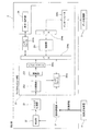
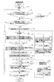
本発明の第1実施形態による血液分析装置1は、図1に示すように、生体試料である血液の測定を行う機能を有する測定部2と、測定部2から出力された測定データを分析して分析結果を得るデータ処理部3と、検体の処理に用いられる試薬を調製する試薬調製装置4とにより構成されている。測定部2は、フローサイトメトリー法により、血液中の白血球、網状赤血球および血小板の測定を行うように構成されている。なお、フローサイトメトリー法とは、測定試料を含む試料流を形成するとともに、その試料流にレーザ光を照射することによって、測定試料中の粒子(血球)が発する前方散乱光、側方散乱光および側方蛍光を検出する粒子(血球)の測定方法である。
As shown in FIG. 1, the
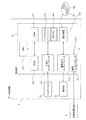
測定部2は、図2に示すように、試料調製部21と、測定試料の測定を行う検出部22と、検出部22の出力に対するアナログ処理部23と、表示・操作部24と、測定部2を制御するためのマイクロコンピュータ部25とを備えている。
As shown in FIG. 2, the
また、試料調製部21は、白血球測定用試料と、網状赤血球測定用試料と、血小板測定用試料とを調製するために設けられている。試料調製部21は、図3に示すように、血液が所定量充填されている採血管21aと、血液が吸引されるサンプリングバルブ21bと、反応チャンバ21cとを含んでいる。採血管21aは、取り替え可能であり、血液の交換を行うことが可能であるように構成されている。また、サンプリングバルブ21bは、吸引ピペット(図示せず)により吸引された採血管21aの血液を所定の量だけ定量する機能を有する。また、サンプリングバルブ21bは、吸引された血液に所定の試薬を混合することが可能となるように構成されている。つまり、サンプリングバルブ21bは、所定量の血液に試薬調製装置4から供給される所定量の試薬が混合された希釈試料を生成可能に構成されている。反応チャンバ21cは、サンプリングバルブ21bから供給される希釈試料に所定の染色液をさらに混合して所定の時間反応させるように構成されている。これにより、試料調製部21は、白血球測定用試料として、白血球が染色されるとともに、赤血球が溶血された測定試料を調製する機能を有する。また、試料調製部21は、網状赤血球測定用試料として、網状赤血球が染色された測定試料を調製するとともに、血小板測定用試料として、血小板が染色された測定試料を調製する機能を有する。
The
また、試料調製部21は、白血球分類測定(以下、「DIFF測定」という)モード時に、白血球測定用試料をシース液とともに試料調製部21から後述するシースフローセル22c(図4参照)に供給するように構成されている。また、試料調製部21は、網状赤血球測定(以下、「RET測定」という)モード時に、網状赤血球測定用試料をシース液とともに試料調製部21からシースフローセル22cに供給するように構成されている。また、試料調製部21は、血小板測定(以下、「PLT測定」という)モード時に、血小板測定用試料をシース液とともに試料調製部21からシースフローセル22cに供給するように構成されている。
The
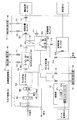
検出部22は、図4に示すように、レーザ光を出射する発光部22aと、照射レンズユニット22bと、レーザ光が照射されるシースフローセル22cと、発光部22aから出射されるレーザ光が進む方向の延長線上に配置されている集光レンズ22d、ピンホール22eおよびPD(フォトダイオード)22fと、発光部22aから出射されるレーザ光が進む方向と交差する方向に配置されている集光レンズ22g、ダイクロイックミラー22h、光学フィルタ22i、ピンホール22jおよびAPD(アバランシェフォトダイオード)22kと、ダイクロイックミラー22hの側方に配置されているPD22lとを含んでいる。
As shown in FIG. 4, the
発光部22aは、シースフローセル22cの内部を通過する測定試料を含む試料流に対して光を出射するために設けられている。また、照射レンズユニット22bは、発光部22aから出射された光を平行光にするために設けられている。また、PD22fは、シースフローセル22cから出射された前方散乱光を受光するために設けられている。なお、シースフローセル22cから出射された前方散乱光により、測定試料中の粒子(血球)の大きさに関する情報を得ることが可能である。
The
ダイクロイックミラー22hは、シースフローセル22cから出射された側方散乱光および側方蛍光を分離するために設けられている。具体的には、ダイクロイックミラー22hは、シースフローセル22cから出射された側方散乱光をPD22lに入射させるとともに、シースフローセル22cから出射された側方蛍光をAPD22kに入射させるために設けられている。また、PD22lは、側方散乱光を受光するために設けられている。なお、シースフローセル22cから出射された側方散乱光により、測定試料中の粒子(血球)の核の大きさなどの内部情報を得ることが可能である。また、APD22kは、側方蛍光を受光するために設けられている。なお、シースフローセル22cから出射された側方蛍光により、測定試料中の粒子(血球)の染色度合いに関する情報を得ることが可能である。また、PD22f、22lおよびAPD22kは、それぞれ、受光した光信号を電気信号に変換する機能を有する。
The
アナログ処理部23は、図4に示すように、アンプ23a、23bおよび23cを含んでいる。また、アンプ23a、23bおよび23cは、それぞれ、PD22f、22lおよびAPD22kから出力された電気信号を増幅および波形処理するために設けられている。
As shown in FIG. 4, the
マイクロコンピュータ部25は、図2に示すように、制御用プロセッサおよび制御用プロセッサを動作させるためのメモリを有する制御部251と、アナログ処理部23から出力された信号をデジタル信号に変換するA/D変換部252と、A/D変換部252から出力されたデジタル信号に所定の処理を行うための演算部253とを含んでいる。制御部251は、バス254aおよびインターフェース255aを介して試料調製部21および検出部22を制御する機能を有する。また、制御部251は、バス254aおよびインターフェース255bを介して表示・操作部24と接続されるとともに、バス254bおよびインターフェース255cを介してデータ処理部3と接続されている。また、演算部253は、演算結果をインターフェース255dおよびバス254aを介して制御部251に出力する機能を有する。また、制御部251は、演算結果(測定データ)をデータ処理部3に送信する機能を有する。
As shown in FIG. 2, the
データ処理部3は、図1に示すように、パーソナルコンピュータ(PC)などからなり、測定部2の測定データを分析するとともに、その分析結果を表示する機能を有する。また、データ処理部3は、制御部31と、表示部32と、入力デバイス33とを含んでいる。制御部31は、測定モード情報を含む測定開始信号およびシャットダウン信号を測定部2に送信する機能を有する。また、制御部31は、図5に示すように、CPU31aと、ROM31bと、RAM31cと、ハードディスク31dと、読出装置31eと、入出力インターフェース31fと、画像出力インターフェース31gと、通信インターフェース31iとにより構成されている。CPU31a、ROM31b、RAM31c、ハードディスク31d、読出装置31e、入出力インターフェース31f、画像出力インターフェース31gおよび通信インターフェース31iは、バス31hによって接続されている。
As shown in FIG. 1, the
CPU31aは、ROM31bに記憶されているコンピュータプログラムおよびRAM31cにロードされたコンピュータプログラムを実行するために設けられている。ROM31bは、マスクROM、PROM、EPROM、EEPROMなどによって構成されており、CPU31aに実行されるコンピュータプログラムおよびこれに用いるデータなどが記録されている。
The
RAM31cは、SRAMまたはDRAMなどによって構成されている。RAM31cは、ROM31bおよびハードディスク31dに記録されているコンピュータプログラムの読み出しに用いられる。また、これらのコンピュータプログラムを実行するときに、CPU31aの作業領域として利用される。
The
ハードディスク31dは、オペレーティングシステムおよびアプリケーションプログラムなど、CPU31aに実行させるための種々のコンピュータプログラムおよびそのコンピュータプログラムの実行に用いるデータがインストールされている。後述するアプリケーションプログラム34aも、このハードディスク31dにインストールされている。
The
読出装置31eは、フレキシブルディスクドライブ、CD−ROMドライブ、またはDVD−ROMドライブなどによって構成されており、可搬型記録媒体34に記録されたコンピュータプログラムまたはデータを読み出すことができる。また、可搬型記録媒体34には、コンピュータに所定の機能を実現させるためのアプリケーションプログラム34aが格納されており、データ処理部3としてのコンピュータがその可搬型記録媒体34からアプリケーションプログラム34aを読み出し、そのアプリケーションプログラム34aをハードディスク31dにインストールすることが可能である。
The
なお、上記アプリケーションプログラム34aは、可搬型記録媒体34によって提供されるのみならず、電気通信回線(有線、無線を問わない)によってデータ処理部3と通信可能に接続された外部の機器から上記電気通信回線を通じて提供することも可能である。たとえば、上記アプリケーションプログラム34aがインターネット上のサーバコンピュータのハードディスク内に格納されており、このサーバコンピュータにデータ処理部3がアクセスして、そのアプリケーションプログラム34aをダウンロードし、これをハードディスク31dにインストールすることも可能である。
Note that the
また、ハードディスク31dには、たとえば、米マイクロソフト社が製造販売するWindows(登録商標)などのグラフィカルユーザインタフェース環境を提供するオペレーティングシステムがインストールされている。以下の説明においては、本実施形態に係るアプリケーションプログラム34aは上記オペレーティングシステム上で動作するものとしている。
In addition, an operating system that provides a graphical user interface environment, such as Windows (registered trademark) manufactured and sold by Microsoft Corporation, is installed in the
入出力インターフェース31fは、たとえば、USB、IEEE1394、RS−232Cなどのシリアルインタフェース、SCSI、IDE、IEEE1284などのパラレルインタフェース、およびD/A変換器、A/D変換器などからなるアナログインタフェースなどから構成されている。入出力インターフェース31fには、キーボードおよびマウスからなる入力デバイス33が接続されており、ユーザがその入力デバイス33を使用することにより、データ処理部3にデータを入力することが可能である。また、入力デバイス33は、測定モードを受け付ける機能を有する。
The input /
画像出力インターフェース31gは、LCDまたはCRTなどで構成された表示部32に接続されており、CPU31aから与えられた画像データに応じた映像信号を表示部32に出力するようになっている。表示部32は、入力された映像信号にしたがって、画像(画面)を表示する。
The
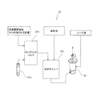
試薬調製装置4は、測定部2の試料調製部21で用いられる試薬を調製するために設けられている。具体的には、試薬調製装置4は、水道水から作製されるRO水を希釈用液体として用いて高濃度試薬を希釈することにより、血液分析に用いられる試薬を調製するように構成されている。ここで、RO水とは、RO(Reverse Osmosis)膜(逆浸透膜)を透過することによって、不純物を取り除かれた水である。
The reagent preparation device 4 is provided for preparing a reagent used in the
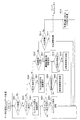
図6に示すように、試薬調製装置4は、高濃度試薬が収容された高濃度試薬タンク5から高濃度試薬を定量して供給するための試薬定量タンク41と、高濃度試薬を希釈するためのRO水を定量して供給するためのRO水定量タンク42と、高濃度試薬とRO水とを収容し、血液の分析に用いられる試薬を調製する試薬調製タンク43と、RO水用定量ポンプ(ダイヤフラムポンプ)44と、調製された試薬を貯留するための試薬貯留タンク45と、水道水からRO水を作製するRO水作製部46と、試薬調製装置4の動作を統括する制御部47とを含んでいる。
As shown in FIG. 6, the reagent preparing device 4 is configured to quantitate and supply a high-concentration reagent from a high-concentration reagent tank 5 in which a high-concentration reagent is stored, and to dilute the high-concentration reagent. RO water quantification tank 42 for quantifying and supplying the RO water, reagent preparation tank 43 for containing a high concentration reagent and RO water, and preparing a reagent used for blood analysis, and RO water metering pump (Diaphragm pump) 44, a reagent storage tank 45 for storing the prepared reagent, an RO water preparation unit 46 for preparing RO water from tap water, and a
また、試薬調製装置4の外部には、装置内の各液体の移動を制御するために、陽圧を印加する陽圧源61、および、陰圧を印加する陰圧源62を含む空圧装置6(図1参照)が設けられている。また、陽圧源61および陰圧源62は、それぞれ、試薬調製装置4の所定の各部に接続されている。
In addition, in order to control the movement of each liquid in the apparatus, a pneumatic apparatus including a
試薬定量タンク41には、タンク内の高濃度試薬の量を検出するための液量センサSE1が設けられている。また、試薬定量タンク41は、電磁バルブV1を介して高濃度試薬タンク5に接続され、電磁バルブV2を介して陰圧源62に接続されている。電磁バルブV1および電磁バルブV2が開放されることによって、試薬定量タンク41に陰圧が印加され、高濃度試薬タンク5から試薬定量タンク41に高濃度試薬が供給されるように構成されている。また、液量センサSE1が高濃度試薬が所定量に到達したことを検出すると、電磁バルブV1および電磁バルブV2が閉じられて、高濃度試薬の供給が停止されるように構成されている。これにより、所定量の高濃度試薬が定量されるように構成されている。
The reagent fixed amount tank 41 is provided with a liquid amount sensor SE1 for detecting the amount of the high concentration reagent in the tank. The reagent fixed amount tank 41 is connected to the high concentration reagent tank 5 through the electromagnetic valve V1, and is connected to the
RO水定量タンク42には、タンク内のRO水の量を検出するための液量センサSE2と、タンク内のRO水の電気伝導度を検出する導電率センサSE3と、タンク内のRO水の温度を測定する温度センサSE4とが設けられている。また、RO水定量タンク42は、電磁バルブV3を介して陰圧源62に接続され、電磁バルブV4を介して後述するRO水作製部46のRO水貯留タンク46aに接続されている。電磁バルブV3および電磁バルブV4が開放されることによって、RO水定量タンク42に陰圧が印加され、RO水貯留タンク46aからRO水定量タンク42にRO水が供給されるように構成されている。また、液量センサSE2がRO水が所定量に到達したことを検出すると、電磁バルブV3および電磁バルブV4が閉じられて、RO水の供給が停止されるように構成されている。これにより、所定量のRO水が定量されるように構成されている。
The RO water quantitative tank 42 includes a liquid amount sensor SE2 for detecting the amount of RO water in the tank, a conductivity sensor SE3 for detecting the electrical conductivity of the RO water in the tank, and the RO water in the tank. A temperature sensor SE4 for measuring the temperature is provided. The RO water fixed amount tank 42 is connected to a
また、試薬定量タンク41は電磁バルブV5を介して陽圧源61に接続されるとともに、試薬定量タンク41と試薬調製タンク43とは、電磁バルブV6を介して接続されている。そして、電磁バルブV5および電磁バルブV6が開放されることによって、試薬定量タンク41に陽圧が印加され、試薬定量タンク41から試薬調製タンク43に所定量の高濃度試薬が供給されるように構成されている。また、電磁バルブV5および電磁バルブV6は、試薬定量タンク41内の高濃度試薬が試薬調製タンク43に供給された後、閉じられるように構成されている。また、RO水定量タンク42は、電磁バルブV7を介して陽圧源61に接続されるとともに、RO水定量タンク42と試薬調製タンク43とは、電磁バルブV8を介して接続されている。そして、電磁バルブV7および電磁バルブV8が開放されることによって、RO水定量タンク42に陽圧が印加され、RO水定量タンク42から試薬調製タンク43に所定量のRO水が供給されるように構成されている。また、電磁バルブV7および電磁バルブV8は、RO水定量タンク42内のRO水が試薬調製タンク43に供給された後、閉じられるように構成されている。
The reagent fixed amount tank 41 is connected to the
ここで、試薬調製装置4は、試薬調製タンク43内において、高濃度試薬がRO水により25倍に希釈されるよう構成されている。具体的には、試薬調製タンク43内における高濃度試薬とRO水との混合比率が1:24(希釈倍率25倍)になるように、RO水定量タンク42から試薬調製タンク43にRO水が供給され、試薬定量タンク41から試薬調製タンク43に高濃度試薬が供給される。
Here, the reagent preparation device 4 is configured so that the high concentration reagent is diluted 25 times with RO water in the reagent preparation tank 43. Specifically, the RO water is supplied from the RO water fixed amount tank 42 to the reagent preparing tank 43 so that the mixing ratio of the high concentration reagent and the RO water in the reagent preparing tank 43 is 1:24 (
また、試薬調製タンク43には、供給された高濃度試薬とRO水とを混合攪拌する攪拌部43aが設けられ、攪拌部43aは、モータ43bにより駆動されるように構成されている。さらに、試薬調製タンク43には、攪拌部43aにより高濃度試薬とRO水とが混合攪拌された試薬の電気伝導度を検出する2つの導電率センサSE5およびSE6と、攪拌部43aにより高濃度試薬とRO水とが混合攪拌された試薬の温度を測定する温度センサSE7とが設けられている。また、導電率センサSE5およびSE6は、それぞれ試薬調製タンク43内の異なる位置に配置されている。
The reagent preparation tank 43 is provided with a stirring
RO水用定量ポンプ(ダイヤフラムポンプ)44は、RO水を吐出する機能を有しており、試薬調製タンク43内の試薬を所望の濃度に希釈するために、所定量のRO水を徐々に試薬調製タンク43に供給することが可能なように構成されている。 The RO water metering pump (diaphragm pump) 44 has a function of discharging RO water, and gradually dilutes a predetermined amount of RO water into the reagent in order to dilute the reagent in the reagent preparation tank 43 to a desired concentration. It is configured so that it can be supplied to the preparation tank 43.
RO水用定量ポンプ44は、電磁バルブV9を介して陰圧源62に接続されている。そして、電磁バルブV7および電磁バルブV9が開放されることによって、RO水用定量ポンプ44に陰圧が印加されるとともに、RO水定量タンク42に陽圧が印加され、RO水定量タンク42からRO水用定量ポンプ44にRO水が供給されるように構成されている。また、RO水用定量ポンプ44は、電磁バルブV10を介して陽圧源61にも接続されるとともに、試薬調製タンク43には、大気開放されるように電磁バルブV11が設けられている。電磁バルブV10および電磁バルブV11が開放されることによって、RO水用定量ポンプ44に陽圧が印加され、RO水用定量ポンプ44から試薬調製タンク43に所定量のRO水が供給されるように構成されている。
The RO water metering pump 44 is connected to the
また、試薬調製タンク43と試薬貯留タンク45とは、電磁バルブV12を介して接続されている。そして、電磁バルブV11および電磁バルブV12が開放されることによって、試薬調製タンク43内の圧力が大気開放され、試薬調製タンク43から試薬調製タンク43の下方に設けられた試薬貯留タンク45に、所望の濃度に希釈された試薬が供給されるように構成されている。また、試薬貯留タンク45には、タンク内の試薬の量を検出するための液量センサSE8が設けられている。また、液量センサSE8の検出結果に基づいて、新たに所望の濃度の試薬を調製するか否かが制御部47によって判断されるように構成されている。また、試薬貯留タンク45は、測定部2に接続されており、試薬調製タンク45内の試薬を測定部2に供給可能なように構成されている。
The reagent preparation tank 43 and the reagent storage tank 45 are connected via an electromagnetic valve V12. Then, when the electromagnetic valve V11 and the electromagnetic valve V12 are opened, the pressure in the reagent preparation tank 43 is released to the atmosphere, and the reagent storage tank 45 provided below the reagent preparation tank 43 is supplied to the desired amount from the reagent preparation tank 43. The reagent diluted to a concentration of 1 is supplied. The reagent storage tank 45 is provided with a liquid amount sensor SE8 for detecting the amount of the reagent in the tank. Further, the
RO水作製部46は、高濃度試薬を希釈するための希釈用液体としてのRO水を、水道水を用いて作製することが可能なように構成されている。これにより、試薬調製装置4以外に、RO水を作製するための装置を別途設ける必要がない。また、RO水作製部46は、RO水貯留タンク46aと、RO膜46bと、水道水に含まれる不純物を取り除くことによって、RO膜46bを保護するフィルタ46cと、水分子がRO膜46bを透過するようにフィルタ46cを通過した水に高圧をかける高圧ポンプ46dと、水道水の供給を制御する電磁バルブV13とを含んでいる。
The RO water preparation unit 46 is configured so that RO water as a dilution liquid for diluting a high concentration reagent can be prepared using tap water. Thereby, it is not necessary to separately provide an apparatus for producing RO water other than the reagent preparation apparatus 4. In addition, the RO water preparation unit 46 removes impurities contained in the RO water storage tank 46a, the
RO水貯留タンク46aは、RO膜46bを透過したRO水を貯留するために設けられている。また、RO水貯留タンク46aには、タンク内のRO水の量を検出するための液量センサSE9が設けられており、液量センサSE9の検出結果に基づいて、RO水が作製される。これにより、常に所定量のRO水をRO水貯留タンク46aに確保しておくことが可能である。RO水作製の一連の流れは、まず、電磁バルブV13が開放されて、水道水がフィルタ46cに到達される。そして、フィルタ46cを通過した水は、RO膜46bを透過するように高圧ポンプ46dによって圧力が印加され、RO膜46bを透過したRO水が貯留タンク46aに供給される。また、RO膜46bを透過しない不純物を含む水は、試薬調製装置4の外部に排出される。
The RO water storage tank 46a is provided for storing RO water that has permeated through the
図7に示すように、制御部47は、CPU47aと、ROM47bと、RAM47cと、データ処理部3に接続される通信インターフェース47dと、各回路を介して、試薬調製装置4内の各部に接続されるI/O(Input/Output)部47eとを含んでいる。
As shown in FIG. 7, the
CPU47aは、ROM47bに記憶されているコンピュータプログラムおよびRAM47cにロードされたコンピュータプログラムを実行するために設けられている。また、CPU47aは、これらのコンピュータプログラムを実行するときに、RAM47cを作業領域として利用する。
The
また、第1実施形態では、CPU47aは、RO水定量タンク42内のRO水の電気伝導度を導電率センサSE3により検出し、検出値Y1をRAM47cに記憶する。また、CPU47aは、RO水定量タンク42内のRO水の温度を温度センサSE4により測定し、測定値T1もRAM47cに記憶するように構成されている。
In the first embodiment, the
また、CPU47aは、試薬調製タンク43に設けられた導電率センサSE5により検出された検出値YS5と、導電率センサSE6により検出された検出値YS6とが実質的に同じ値になるように、モータ43bに攪拌部43aを駆動させるように構成されている。具体的には、CPU47aは、2つの検出値の差の絶対値|YS5−YS6|が所定値Mより小さいか否かを判断し、所定値Mより小さくなるようにモータ43bに攪拌部43aを駆動させる。これにより、試薬調製タンク43内で検出される試薬の電気伝導度が、導電率センサの位置によってばらつくのを抑制することが可能である。また、CPU47aは、絶対値|YS5−YS6|が所定値Mより小さくなった時に、試薬調製タンク43内の試薬の電気伝導度を導電率センサSE5により検出し、その時の検出値Y2をRAM47cに記憶する。また、この時、CPU47aは、試薬調製タンク43内の試薬の温度も温度センサSE7により測定し、測定値T2をRAM47cに記憶するように構成されている。
Further, the
また、CPU47aは、導電率センサSE5による検出値Y2が、高濃度試薬を所望の濃度に希釈するための電気伝導度の目標値Zに対して所定の範囲内にあるように、RO水定量タンク42を用いて(必要な場合には、RO水用定量ポンプ44も用いて)、RO水を試薬調製タンク43に供給するように構成されている。次に、試薬の電気伝導度の目標値を求める一般式を以下の式(1)に示す。
Further, the
Z0={X+(A−1)Y}/A・・・・・(1)
上記式(1)において、Z0は、高濃度試薬とRO水とが混合攪拌された試薬の25℃における電気伝導度の目標値(ms/cm)、Xは、高濃度試薬の25℃における電気伝導度(ms/cm)、Yは、RO水の25℃における電気伝導度(ms/cm)、Aは、希釈倍率(既知)(第1実施形態では25倍)をそれぞれ表す。なお、Xは、高濃度試薬固有の値であり、予め実験などにより得られた既知の値である。Z 0 = {X + (A−1) Y} / A (1)
In the above formula (1), Z 0 is a target value (ms / cm) of electric conductivity at 25 ° C. of a reagent in which a high concentration reagent and RO water are mixed and stirred, and X is a high concentration reagent at 25 ° C. Electrical conductivity (ms / cm), Y represents the electrical conductivity of RO water at 25 ° C. (ms / cm), and A represents the dilution factor (known) (25 times in the first embodiment). X is a value unique to the high concentration reagent, and is a known value obtained in advance through experiments or the like.
また、RO水の温度および高濃度試薬とRO水とが混合攪拌された試薬の温度の変動を考慮するための補正式を以下の式(2)に示す。 Further, the following equation (2) shows a correction equation for considering the temperature of the RO water and the temperature variation of the reagent in which the high concentration reagent and the RO water are mixed and stirred.
Z=[{X+(A−1)Y}/A]×{1+α1(T2−25)}=[[X+(A−1)Y1/{1+α0(T1−25)}]/A]×{1+α1(T2−25)}・・・・・(2)
上記式(2)において、Zは、高濃度試薬とRO水とが混合攪拌された試薬のT2℃における電気伝導度の目標値(ms/cm)、Y1は、RO水のT1℃における電気伝導度(ms/cm)、T1は、RO水の温度(℃)、T2は、高濃度試薬とRO水とが混合攪拌された試薬の温度(℃)、α0は、RO水の電気伝導度の25℃に対する温度係数、α1は、高濃度試薬とRO水とが混合攪拌された試薬の電気伝導度の25℃に対する温度係数をそれぞれ表す。なお、温度係数α0およびα1は、液体の種類や濃度によって異なるが、JIS(日本工業規格)では、簡易的に0.02が用いられる。Z = [{X + (A−1) Y} / A] × {1 + α1 (T2-25)} = [[X + (A−1) Y1 / {1 + α0 (T1-25)}] / A] × {1 + α1 (T2-25)} (2)
In the above formula (2), Z is a target value (ms / cm) of electric conductivity at T2 ° C. of a reagent in which a high concentration reagent and RO water are mixed and stirred, and Y1 is electric conductivity at T1 ° C. of RO water. Degree (ms / cm), T1 is the temperature (° C.) of the RO water,
第1実施形態では、CPU47aは、上記した式(2)により目標値Zを算出するように構成されている。したがって、CPU47aは、所望する希釈倍率A(既知)、RO水の電気伝導度の検出値Y1、RO水の温度の測定値T1、混合攪拌された試薬の温度の測定値T2および高濃度試薬の電気伝導度X(既知)に基づいて、目標値を決定する。
In the first embodiment, the
通信インターフェース47dは、ユーザが試薬調製装置4内で発生したエラーを容易に認知できるように、エラー情報をデータ処理部3に伝達可能なように構成されている。このエラー情報に基づいて、データ処理部3の表示部32にエラー通知が表示されるように構成されている。
The
I/O部47eは、図7に示すように、各センサ回路を介して、各センサSE1〜S9から信号が入力されるように構成されている。また、I/O部47eは、各駆動回路を介して、電磁バルブV1〜V13、モータ43bおよび高圧ポンプ46dの駆動を制御するために、各駆動回路に信号を出力するように構成されている。
As shown in FIG. 7, the I /
次に、図6および図8を参照して、本発明の第1実施形態による血液分析装置1の試薬調製処理動作について説明する。
Next, with reference to FIGS. 6 and 8, the reagent preparation processing operation of the
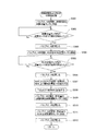
まず、図8のステップS1において、CPU47aにより、ROM47bに記憶されているコンピュータプログラムの初期化が行われる。次に、ステップS2において、CPU47aにより、RO水貯留タンク46aに設けられた液量センサSE9が液体を検出したか否かが判断され、液量センサSE9が液体を検出していない場合、すなわち、所定量のRO水がRO水貯留タンク46aに貯留されていない場合には、ステップS3において、CPU47aは、RO水作製部46によりRO水の作製処理を行う。ステップS3におけるRO水の作製処理については後述する。液量センサSE9が液体を検出した場合には、ステップS4において、CPU47aにより、試薬貯留タンク45の液量センサSE8が液体を検出したか否かが判断される。液量センサSE8が液体を検出した場合、すなわち、所定量の試薬が試薬貯留タンク45に貯留されている場合には、測定部2で使用するための試薬が所定量確保されているので、新たに試薬を作製することなくステップS15に移行される。液量センサSE8が液体を検出していない場合には、新たに試薬を作製するために、ステップS5において、CPU47aにより、試薬調製タンク43への高濃度試薬およびRO水の供給処理が行われる。ステップS5における高濃度試薬およびRO水の供給処理については後述する。
First, in step S1 of FIG. 8, the
ステップS6において、CPU47aは、試薬調製タンク43に供給された高濃度試薬およびRO水を攪拌部43aにより混合攪拌する。そして、ステップS7において、CPU47aは、導電率センサSE5により、試薬調製タンク43内の試薬の電気伝導度YS5を検出するとともに、導電率センサSE6により、試薬調製タンク43内の試薬の電気伝導度YS6を検出する。次に、ステップS8において、CPU47aにより、検出値YS5とYS6との差の絶対値|YS5−YS6|が所定値Mよりも小さいか否かが判断され、所定値Mよりも小さくない場合には、検出位置による電気伝導度のばらつきがあるということなので、攪拌部43aによる攪拌が繰り返される。絶対値|YS5−YS6|が所定値Mよりも小さくなった場合には、ステップS9において、CPU47aは、その時の試薬調製タンク43内の試薬の温度T2を温度センサSE7により測定するとともに、その試薬の電気伝導度Y2を導電率センサSE5により検出する。
In step S6, the
そして、ステップS10において、CPU47aにより、測定値T2および検出値Y2がRAM47cに記憶され、ステップS11において、上記式(2)により試薬調製タンク43内の試薬の電気伝導度の目標値Zが算出される。次に、ステップS12において、CPU47aにより、目標値Zと検出値Y2との差(Z−Y2)が所定値N1(負の値)よりも大きいか否かが判断され、差(Z−Y2)が所定値N1より小さい場合には、さらにRO水を試薬調製タンク43に供給する必要があるので、ステップS17において、RO水用定量ポンプ44にRO水を供給するために、電磁バルブV7および電磁バルブV9が開放される。RO水用定量ポンプ44にRO水が供給された後、ステップS18において、CPU47aにより、電磁バルブV7および電磁バルブV9が閉じられ、ステップS19において、電磁バルブV10および電磁バルブV11が開放されることによって、RO水用定量ポンプ44から試薬調製タンク43に所定量のRO水が追加供給される。RO水が追加供給されることによって試薬調製タンク43内の試薬の電気伝導度にばらつきが生じるので、ステップS6に移行され、再度混合攪拌が行われる。
In step S10, the measured value T2 and the detected value Y2 are stored in the
差(Z−Y2)が所定値N1(負の値)よりも大きくなった場合には、ステップS13において、CPU47aにより、差(Z−Y2)が所定値N2より小さいか否かが判断される。差(Z−Y2)が所定値N2より大きい場合には、試薬調製タンク43内の試薬が所望の濃度よりも薄くなってしまったため、ステップS20において、CPU47aにより、所望の濃度の試薬が調製されなかったことを示す警報情報が、通信インターフェース47dを介してデータ処理部3に送信される。データ処理部3のCPU31aは、通信インターフェース31iを介して前述の警報情報を受信すると、試薬調製装置4において所望の濃度の試薬が調製されなかった旨のメッセージを表示部32に表示する。これにより、ユーザは、試薬が所望の濃度に調製されなかったことを容易に知ることができる。次に、ステップS21において、CPU47aにより、電磁バルブV11および電磁バルブV14が開放されて、試薬調製タンク43内の試薬が試薬調製装置4の外に排出される。そして、試薬調製タンク43内の試薬が試薬調製装置4の外に排出されると、ステップS22において、CPU47aにより、電磁バルブV11および電磁バルブV14が閉じられる。
When the difference (Z−Y2) is larger than the predetermined value N1 (negative value), in step S13, the
差(Z−Y2)が所定値N2より小さい場合には、ステップS14において、CPU47aにより、電磁バルブV11および電磁バルブV12が開放されて、電気伝導度が実質的に目標値Zに同じになるように調製された試薬が試薬貯留タンク45に供給される。すなわち、所望の濃度に希釈された試薬が試薬貯留タンク45に貯留されることになる。そして、試薬調製タンク43内の試薬が全て試薬貯留タンク45に供給された後、ステップS15において、CPU47aにより、電磁バルブV11および電磁バルブV12が閉じられ、ステップS16において、試薬調製装置4のシャットダウン指示の有無が判断される。シャットダウン指示があった場合には、試薬調製装置4の動作が終了され、シャットダウン指示がない場合には、ステップS2に移行される。
When the difference (Z−Y2) is smaller than the predetermined value N2, the
次に、図6および図9を参照して、図8に示した試薬調製処理動作のステップS3におけるRO水作製処理動作について説明する。 Next, with reference to FIG. 6 and FIG. 9, the RO water production processing operation in step S3 of the reagent preparation processing operation shown in FIG. 8 will be described.
まず、図9のステップS301において、CPU47aにより、電磁バルブV13が開放され、水道水がフィルタ46cを通過する。ステップS302において、CPU47aにより、高圧ポンプ46dが駆動され、フィルタ46cを通過した水が高圧によりRO膜46bを透過する。そして、ステップS303において、CPU47aにより、RO水貯留タンク46aの液量センサSE9が液体を検出したか否かが判断される。すなわち、RO水貯留タンク46a内に所定量のRO水が貯留されているか否かが判断される。液量センサSE9が液体を検出していない場合には、この判断が繰り返され、RO水貯留タンク46aに継続してRO膜46bを透過したRO水が供給される。一方、液量センサSE9が液体を検出した場合には、ステップS304において、CPU47aにより、電磁バルブV13が閉じられ、高圧ポンプ46dの駆動も停止されて、動作が終了される。
First, in step S301 in FIG. 9, the electromagnetic valve V13 is opened by the
次に、図6および図10を参照して、図8に示した試薬調製処理動作のステップS5における試薬調製タンク43への高濃度試薬およびRO水の供給処理動作について説明する。 Next, with reference to FIG. 6 and FIG. 10, the supply processing operation of the high concentration reagent and the RO water to the reagent preparation tank 43 in step S5 of the reagent preparation processing operation shown in FIG. 8 will be described.
まず、図10のステップS501において、CPU47aにより、電磁バルブV1および電磁バルブV2が開放され、高濃度試薬タンク5から試薬定量タンク41に高濃度試薬が供給される。次に、ステップS502において、CPU47aにより、試薬定量タンク41の液量センサSE1が液体を検出したか否かが判断される。すなわち、試薬定量タンク41に所定量の高濃度試薬が供給されたか否かが判断される。液量センサSE1が液体を検出していない場合には、液量センサSE1が液体を検出するまでこの判断が繰り返される。一方、高濃度試薬が所定量に到達し、液量センサSE1が液体を検出した場合には、ステップS503において、CPU47aにより、高濃度試薬タンク5からの高濃度試薬の供給を止めるために、電磁バルブV1および電磁バルブV2が閉じられる。
First, in step S501 of FIG. 10, the
そして、ステップS504において、CPU47aにより、電磁バルブV3および電磁バルブV4が開放されて、RO水貯留タンク46aからRO水定量タンク42にRO水が供給される。次に、ステップS505において、CPU47aにより、RO水定量タンク42の液量センサSE2が液体を検出したか否かが判断される。すなわち、RO水定量タンク42に所定量のRO水が供給されたか否かが判断される。液量センサSE2が液体を検出していない場合には、液量センサSE2が液体を検出するまで、RO水のRO水定量タンク42への供給が継続される。RO水が所定量供給されることによって、液量センサSE2が液体を検出した場合には、ステップS506において、CPU47aにより、電磁バルブV3および電磁バルブV4が閉じられて、RO水貯留タンク46aからRO水定量タンク42への供給が終了される。そして、ステップS507において、CPU47aは、温度センサSE4によりRO水定量タンク42内のRO水の温度T1を測定するとともに、導電率センサSE3によりRO水の電気伝導度Y1を検出する。そして、ステップS508において、CPU47aにより、上記測定値T1および検出値Y1がRAM47cに記憶される。
In step S504, the
次に、ステップS509において、CPU47aにより、電磁バルブV5および電磁バルブV6が開放されて、試薬定量タンク41から試薬調製タンク43に所定量の高濃度試薬が供給され、ステップS510において、電磁バルブV5および電磁バルブV6が閉じられる。続いて、ステップS511において、CPU47aにより、電磁バルブV7および電磁バルブV8が開放され、RO水定量タンク42から試薬調製タンク43に所定量のRO水が供給された後、ステップS512において、電磁バルブV7および電磁バルブV8が閉じられ、動作が終了される。
Next, in step S509, the
第1実施形態では、上記のように、制御部47は、RO水の電気伝導度を検出する導電率センサSE3により検出された検出値Y1に基づいて、高濃度試薬とRO水とが混合攪拌された試薬の電気伝導度の目標値Zを決定し、高濃度試薬とRO水とが混合攪拌された試薬の電気伝導度を検出する導電率センサSE5により検出された検出値Y2が目標値Zに近づくように、RO水用定量ポンプ44の供給動作を制御するよう構成されている。そのため、RO水の電気伝導度が変動する場合にも、変動した値に基づいた目標値Zを決定し、高濃度試薬とRO水とが混合攪拌された試薬の電気伝導度を目標値Zに近づけることができる。その結果、高濃度試薬を所望の濃度に希釈することができる。
In the first embodiment, as described above, the
また、第1実施形態では、RO水の電気伝導度を検出する導電率センサSE3、RO水の温度を測定する温度センサSE4、高濃度試薬とRO水とが混合攪拌された試薬の電気伝導度を検出する導電率センサSE5、および、高濃度試薬とRO水とが混合攪拌された試薬の温度を測定する温度センサSE7が設けられ、制御部47は、所望の希釈倍率A(既知)、導電率センサSE3により検出された検出値Y1、温度センサSE4により測定された測定値T1、温度センサSE7により測定された測定値T2および高濃度試薬の電気伝導度X(既知)に基づいて、高濃度試薬とRO水とが混合攪拌された試薬の電気伝導度の目標値Zを決定するように構成されている。そのため、RO水の電気伝導度Y1のみならず、電気伝導度に相関する温度T1およびT2にも基づいて、高濃度試薬とRO水とが混合攪拌された試薬の電気伝導度の目標値Zが決定されるので、高濃度試薬を精度よく所望の濃度に希釈することができる。
In the first embodiment, the conductivity sensor SE3 that detects the electrical conductivity of the RO water, the temperature sensor SE4 that measures the temperature of the RO water, and the electrical conductivity of the reagent in which the high concentration reagent and the RO water are mixed and stirred. And a temperature sensor SE7 for measuring the temperature of the reagent in which the high-concentration reagent and the RO water are mixed and stirred are provided, and the
また、第1実施形態では、制御部47を、高濃度試薬およびRO水のうち、RO水を、混合比率(1:24)に基づく混合量よりも少なめに試薬調製タンク43に供給するとともに、導電率センサSE5により検出される検出値Y2が目標値Zに近づくように、RO水を試薬調製タンク43に徐々に追加供給するように、RO水用定量ポンプ44の供給動作を制御するように構成することによって、高濃度試薬を徐々に追加供給する場合に比べて、試薬調製タンク43内の試薬の電気伝導度の変化量を小さくすることができる。そのため、導電率センサSE5により検出される試薬調製タンク43内の試薬の電気伝導度Y2を微量ずつ変化させながら、精度よく目標値Zに近づけることができる。
In the first embodiment, the
(第2実施形態)
次に、図12および図13を参照して、本発明の第2実施形態による血液分析装置100について説明する。第2実施形態による血液分析装置100は、上記第1実施形態による血液分析装置1と異なり、試薬調製装置104のメンテナンスに関する情報や試薬調製の状態に関する情報などが、データ処理部3の表示部32に表示されるように構成されている。なお、第2実施形態では、検体分析システムの一例である血液分析装置100に本発明を適用した場合について説明する。(Second Embodiment)
Next, with reference to FIGS. 12 and 13, a
第2実施形態による血液分析装置100は、図12に示すように、測定部2と、データ処理部3と、試薬調製装置104とにより構成されている。
As shown in FIG. 12, the
データ処理部3は、通信インターフェース31iがネットワーク200を介してサーバコンピュータ300に接続されている。サーバコンピュータ300には、ネットワーク200を介して複数の血液分析装置100のデータ処理部3が接続されている。
In the
試薬調製装置104は、図13に示すように、上記第1実施形態の試薬調製装置4の構成に加えて、RO水貯留タンク46aにRO水の電気伝導度を検出する導電率センサSE10が設けられている。また、RO水貯留タンク46aは、電磁バルブV15を介して、タンク内のRO水を排出可能に構成されている。
As shown in FIG. 13, in addition to the configuration of the reagent preparation device 4 of the first embodiment, the
次に、図14〜図16を参照して、本発明の第2実施形態による血液分析装置100の試薬調製処理動作について説明する。なお、図14〜図16に示すステップS1〜ステップS22については、それぞれ、図8に示すステップS1〜ステップS22と同様の動作が行われるので、以下では説明を省略する。
Next, the reagent preparation processing operation of the
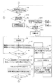
ここで、第2実施形態では、図14のステップS1の後、ステップS201において、CPU47aにより、試薬調製装置104のメンテナンスを行う時期であるか否かが判断される。たとえば、RO水作製部46のフィルタ46cは6ヶ月に1回、RO膜46bは1年〜2年に1回、それぞれ交換を行うように設定されており、RO水作製部46の洗浄は、12週間に1回行うように設定されている。メンテナンスを行う時期でない場合には、ステップS2に移行される。一方、メンテナンスを行う時期である場合には、ステップS202において、メンテナンス実行を要求するメッセージの表示指示情報が通信インターフェース47dを介して、データ処理部3に送信される。
Here, in the second embodiment, after step S1 in FIG. 14, in step S201, the
ここで、図17を参照して、試薬調製装置104からメッセージ表示指示情報が送信された際に、データ処理部3において行われるデータ処理動作について説明する。
Here, a data processing operation performed in the
まず、図17のステップS601において、CPU31aにより、データ通信があったか否かが判断される。具体的には、試薬調製装置104から送信されたメンテナンス実行要求などのメッセージ表示指示情報が、通信インターフェース31iを介して受信されたか否かが判断される。この判断は、メッセージ表示指示情報が受信されるまで繰り返される。
First, in step S601 in FIG. 17, the
そして、ステップS602において、受信情報がメンテナンス実行要求に基づくものであると判断され、ステップS603において、メンテナンス要求画面が表示部32に表示される。具体的には、メンテナンス内容がフィルタ46cおよびRO膜46bの交換である場合、図18に示すように、フィルタ46cおよびRO膜46bのメンテナンス要求画面320が表示部32に表示される。メンテナンス要求画面320には、フィルタ46cおよびRO膜46bのメンテナンスが必要であることを示す「フィルタ・RO膜のメンテナンス時期です」というメッセージが表示される。また、メンテナンス要求画面320には、フィルタ46cおよびRO膜46bの交換を促す「フィルタ・RO膜を交換した後、OKボタンを押してください」というメッセージも表示される。さらに、メンテナンス要求画面320には、メンテナンス処理指示を受け付けるためのOKボタン320aが表示される。
In step S602, it is determined that the received information is based on a maintenance execution request. In step S603, a maintenance request screen is displayed on the
そして、ステップS604において、OKボタン320aの押下状況に基づいて、メンテナンス処理指示を受け付けたか否かが判断され、OKボタン320aが押下されるまでこの判断が繰り返される。メンテナンス処理指示が受け付けられると、ステップS605において、メンテナンス処理指示情報が試薬調製装置104に送信される。
In step S604, it is determined whether a maintenance processing instruction has been accepted based on the pressing state of the
試薬調製装置104では、図14のステップS202でメンテナンス実行要求のメッセージ表示指示情報をデータ処理部3に送信した後、ステップS203において、CPU47aにより、データ処理部3から送信されたメンテナンス処理指示情報が受信されたか否かが判断される。この判断は、メンテナンス処理指示情報が受信されるまで繰り返され、受信されると、ステップS204において、メンテナンス処理が実行される。具体的には、メンテナンス内容に応じて、フィルタ46cおよびRO膜46bの交換処理やRO水作製部46の洗浄処理などが行われる。
In the
次に、ステップS2で所定量のRO水がRO水貯留タンク46aに貯留されていないと判断された場合には、ステップS205において、CPU47aにより、水道水がRO水作製部46に供給されているか否かが判断される。供給されている場合には、ステップS3において、RO水作製処理が行われる。
Next, if it is determined in step S2 that the predetermined amount of RO water is not stored in the RO water storage tank 46a, is the tap water supplied to the RO water preparation unit 46 by the
次に、図19を参照して、図14に示す試薬調製処理動作のステップS3におけるRO水作製処理動作について説明する。なお、図19に示すステップS301〜ステップS304については、それぞれ、図9に示すステップS301〜ステップS304と同様の動作が行われるので、以下では説明を省略する。 Next, with reference to FIG. 19, the RO water preparation processing operation in step S3 of the reagent preparation processing operation shown in FIG. 14 will be described. In addition, about step S301-step S304 shown in FIG. 19, since the operation | movement similar to step S301-step S304 shown in FIG. 9, respectively is performed, description is abbreviate | omitted below.
所定量のRO水がRO水貯留タンク46aに貯留された状態で、図19のステップS304において高圧ポンプ46dの駆動が停止された後、ステップS305において、導電率センサSE10により、タンク内のRO水の電気伝導度が測定される。そして、ステップS306において、水質情報としての電気伝導度の測定結果が、通信インターフェース47dを介してデータ処理部3に送信され、RO水作製処理動作が終了される。
After the predetermined amount of RO water is stored in the RO water storage tank 46a, the driving of the high-pressure pump 46d is stopped in step S304 of FIG. 19, and in step S305, the RO water in the tank is detected by the conductivity sensor SE10. The electrical conductivity of is measured. In step S306, the measurement result of the electrical conductivity as the water quality information is transmitted to the
試薬調製装置104から水質情報が送信されると、データ処理部3では、図17に示すステップS601、S602、S606およびS610の判断を経た後、ステップS614において、受信情報が水質情報であると判断される。そして、ステップS615において、受信した水質情報がネットワーク200を介してサーバコンピュータ300に送信される。送信された水質情報は、サーバコンピュータ300に記憶され、その後RO水作製部46で生じる不具合の内容を判断するための情報として用いられる。また、サーバコンピュータ300には、ネットワーク200を介して接続される複数の血液分析装置100により得られた複数の水質情報が記憶されているので、RO水作製部46の不具合内容を、これら複数の水質情報を用いて判断することが可能である。なお、データ処理部3での受信情報が、メンテナンス実行要求に基づくもの、RO水供給不可に基づくもの、高濃度試薬交換に基づくもの、および、水質情報のいずれでもない場合には、ステップS616において、試薬調製装置104で生じたその他の不具合を示すメッセージ表示など、受信情報に応じたその他の処理が行われる。
When the water quality information is transmitted from the
一方、図14のステップS205で水道水が供給されていないと判断された場合には、ステップS206において、RO水供給不可を示すメッセージの表示指示情報が通信インターフェース47dを介して、データ処理部3に送信される。
On the other hand, if it is determined in step S205 in FIG. 14 that tap water is not supplied, in step S206, a message display instruction information indicating that RO water supply is not possible is sent via the
試薬調製装置104からRO水供給不可を示すメッセージの表示指示情報が送信されると、データ処理部3では、図17に示すステップS601およびS602の判断を経た後、ステップS606において、受信情報がRO水供給不可に基づくものであると判断される。そして、ステップS607において、図20に示すように、RO水供給不可画面321が表示部32に表示される。RO水供給不可画面321には、RO水が供給不能状態であることを示す「RO水が供給されません」というメッセージが表示される。また、RO水供給不可画面321には、この状態を解消するために水道水の供給を促す「水道の蛇口を開放した後、OKボタンを押してください」というメッセージも表示される。さらに、RO水供給不可画面321には、RO水作製処理動作の復帰処理指示を受け付けるためのOKボタン321aが表示される。
When the display instruction information of the message indicating that the RO water supply cannot be supplied is transmitted from the
そして、ステップS608において、OKボタン321aの押下状況に基づいて、復帰処理指示を受け付けたか否かが判断され、OKボタン321aが押下されるまでこの判断が繰り返される。復帰処理指示が受け付けられると、ステップS609において、復帰処理指示情報が試薬調製装置104に送信される。
In step S608, based on the pressing state of the
試薬調製装置104では、図14のステップS206でRO水供給不可を示すメッセージの表示指示情報をデータ処理部3に送信した後、ステップS207において、データ処理部3から送信された復帰処理指示情報が受信されたか否かが判断される。この判断は、復帰処理指示情報が受信されるまで繰り返され、受信されると、ステップS208において、RO水作製処理動作の復帰処理が実行される。具体的には、電磁バルブV15を開放することにより、RO水貯留タンク46aに貯留されているRO水がすべて排出される。これにより、RO水作製処理動作が行われずに、タンク内に長期間放置された古いRO水を排出することができるので、水質の劣る可能性がある古いRO水が試薬の調製に用いられるのを防止することが可能となる。そして、復帰処理が実行された後、動作はステップS2に移行される。
In the
次に、図15に示すステップS4において、所定量の試薬が試薬貯留タンク45に貯留されていないと判断された場合には、ステップS209において、高濃度試薬タンク5から試薬定量タンク41に高濃度試薬が供給可能か否かが判断される。供給可能である場合には、ステップS5において、高濃度試薬およびRO水の供給処理動作が行われる。一方、供給不可である場合には、ステップS210において、高濃度試薬タンク5の交換を促すメッセージの表示指示情報が通信インターフェース47dを介して、データ処理部3に送信される。
Next, when it is determined in step S4 shown in FIG. 15 that a predetermined amount of reagent is not stored in the reagent storage tank 45, a high concentration is transferred from the high concentration reagent tank 5 to the reagent fixed amount tank 41 in step S209. It is determined whether the reagent can be supplied. If it can be supplied, in step S5, a high concentration reagent and RO water supply processing operation is performed. On the other hand, if supply is not possible, display instruction information for a message prompting replacement of the high concentration reagent tank 5 is transmitted to the
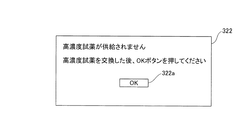
試薬調製装置104から高濃度試薬タンク5の交換を促すメッセージの表示指示情報が送信されると、データ処理部3では、図17に示すステップS601、S602およびS606の判断を経た後、ステップS610において、受信情報が高濃度試薬タンク5の交換を促すためのものであると判断される。そして、ステップS611において、図21に示すように、高濃度試薬交換画面322が表示部32に表示される。高濃度試薬交換画面322には、高濃度試薬が供給不能状態であることを示す「高濃度試薬が供給されません」というメッセージが表示される。また、高濃度試薬交換画面322には、この状態を解消するために高濃度試薬タンク5の交換を促す「高濃度試薬を交換した後、OKボタンを押してください」というメッセージも表示される。さらに、高濃度試薬交換画面322には、交換後の高濃度試薬を用いた試薬調製を行うためのタンク交換処理の指示を受け付けるOKボタン322aが表示される。
When the display instruction information of the message prompting the replacement of the high concentration reagent tank 5 is transmitted from the
そして、ステップS612において、OKボタン322aの押下状況に基づいて、交換処理指示を受け付けたか否かが判断され、OKボタン322aが押下されるまでこの判断が繰り返される。交換処理指示が受け付けられると、ステップS613において、交換処理指示情報が試薬調製装置104に送信される。
In step S612, it is determined whether or not an exchange processing instruction has been accepted based on the pressing state of the
試薬調製装置104では、図15のステップS210で高濃度試薬タンク5の交換を促すメッセージの表示指示情報をデータ処理部3に送信した後、ステップS211において、データ処理部3から送信された交換処理指示情報が受信されたか否かが判断される。この判断は、交換処理指示情報が受信されるまで繰り返され、受信されると、ステップS212において、高濃度試薬タンク5の交換処理が実行される。具体的には、電磁バルブV1および電磁バルブV2が開放され、高濃度試薬タンク5から試薬定量タンク41に高濃度試薬が供給される。そして、動作はステップS4に移行される。
In the
なお、第2実施形態による血液分析装置100のその他の構成は、上記第1実施形態の血液分析装置1と同様である。
In addition, the other structure of the
第2実施形態では、上記のように、試薬調製装置104の状態および試薬調製の状態を検出するCPU47aと、CPU47aにより検出された状態情報を試薬調製装置104の外部に設けられたデータ処理部3に送信するための通信インターフェース47dとを試薬調製装置104に設け、試薬調製装置104から送信された状態情報を受信し、受信した状態情報を表示部32に表示するようにデータ処理部3を構成することによって、試薬調製装置104の状態や試薬調製の状態などを、データ処理部3の表示部32により確認することができるので、試薬調製装置104の状況を視覚を通じて容易に認識することができる。
In the second embodiment, as described above, the
また、第2実施形態では、試薬調製装置104における試薬調製の状態(RO水供給不能状態および高濃度試薬供給不能状態)を解消するための情報を表示部32に表示するようにデータ処理部3を構成することによって、表示部32に表示された情報に基づいて、ユーザは、試薬調製の不具合に対して容易に解消方法を認識することができるので、容易に不具合の対処を行うことができる。
Further, in the second embodiment, the
また、第2実施形態では、試薬調製装置104に対する動作指示(メンテナンス処理指示、復帰処理指示および交換処理指示)を受け付けるOKボタン320a、321aおよび322aを表示部32に表示し、受け付けられた動作指示に基づく動作指示情報を試薬調製装置104に送信するようにデータ処理部3を構成するとともに、受信した動作指示情報に従って動作(メンテナンス処理、復帰処理および交換処理)を実行するように試薬調製装置104を構成することによって、ユーザは、表示部32からの簡易な操作により、試薬調製装置104に対して容易に所定の動作指示を行うことができる。
In the second embodiment,
なお、第2実施形態のその他の効果は、上記第1実施形態と同様である。 The remaining effects of the second embodiment are similar to those of the aforementioned first embodiment.
なお、今回開示された実施形態は、すべての点で例示であって制限的なものではないと考えられるべきである。本発明の範囲は、上記した実施形態の説明ではなく特許請求の範囲によって示され、さらに特許請求の範囲と均等の意味および範囲内でのすべての変更が含まれる。 The embodiment disclosed this time should be considered as illustrative in all points and not restrictive. The scope of the present invention is shown not by the above description of the embodiments but by the scope of claims for patent, and further includes all modifications within the meaning and scope equivalent to the scope of claims for patent.
たとえば、上記第1実施形態では、図8に示される試薬調製処理動作のステップS12において、CPU47aにより、電気伝導度の目標値Zと検出値Y2との差(Z−Y2)が所定値N1より大きいか否かが判断され、差(Z−Y2)が所定値N1より小さい場合には、ステップS17〜19において、RO水定量ポンプ44によりRO水が試薬調製タンク43に追加供給されているが、本発明の実施形態はこれに限られない。以下に、本発明の別実施形態による血液分析装置の試薬調製処理動作について説明する。
For example, in the first embodiment, in step S12 of the reagent preparation processing operation shown in FIG. 8, the
図11に示される試薬調製処理動作においては、まず、図8に示されるステップS1〜11と同様の処理が、CPU47aにより、ステップS101〜111において行われる。
In the reagent preparation processing operation shown in FIG. 11, first, processing similar to steps S <b> 1 to 11 shown in FIG. 8 is performed by the
次に、ステップS112において、CPU47aにより、目標値Zと検出値Y2との差の絶対値|Z−Y2|が所定値Nより小さいか否かが判断される。絶対値|Z−Y2|が所定値Nより大きい場合には、試薬調製タンク43内の試薬が所望の濃度に調製されなかったため、ステップS116において、CPU47aにより、所望の濃度の試薬が調製されなかったことを示す警報情報が、通信インターフェース47dを介してデータ処理部3に送信される。データ処理部3のCPU31aは、通信インターフェース31iを介して前述の警報情報を受信すると、試薬調製装置4において所望の濃度の試薬が調製されなかった旨のメッセージを表示部32に表示する。これにより、ユーザは、試薬が所望の濃度に調製されなかったことを容易に知ることができる。次に、ステップS117において、試薬調製装置4のCPU47aにより、電磁バルブV11および電磁バルブV14が開放され、試薬調製タンク43内の試薬が試薬調製装置4の外に排出される。そして、試薬調製タンク43内の試薬が試薬調製装置4の外に排出された後、ステップS118において、CPU47aにより、電磁バルブV11および電磁バルブV14が閉じられる。
Next, in step S112, the
絶対値|Z−Y2|が所定値Nより小さい場合には、試薬調製タンク43内の試薬が所望の濃度に調製されているため、図8に示されるステップS14〜16と同様の処理が、CPU47aにより、ステップS113〜115において行われる。以上のように、本発明の別実施形態による試薬調製処理動作が行われる。
If the absolute value | Z−Y2 | is smaller than the predetermined value N, the reagent in the reagent preparation tank 43 has been prepared to a desired concentration, and therefore the same processing as steps S14 to S16 shown in FIG. This is performed in steps S113 to S115 by the
また、上記第1実施形態および第2実施形態では、それぞれ、本発明を検体処理装置および検体分析システムの一例である血液分析装置に適用する例を示したが、本発明はこれに限らず、免疫分析装置や生化学分析装置などの分析装置に適用してもよい。また、塗抹標本作製装置など、試薬を用いて検体の処理を行う検体処理装置および検体分析システムであれば、他の検体処理装置および検体分析システムに適用してもよい。 In the first embodiment and the second embodiment, the present invention is applied to a blood analyzer that is an example of a sample processing apparatus and a sample analysis system. However, the present invention is not limited to this, You may apply to analyzers, such as an immune analyzer and a biochemical analyzer. Moreover, as long as it is a sample processing apparatus and sample analysis system that processes a sample using a reagent, such as a smear preparation apparatus, the present invention may be applied to other sample processing apparatuses and sample analysis systems.
また、上記第1実施形態では、高濃度試薬を所望の濃度に希釈するために、電気伝導度の検出値を目標値に近づける例を示したが、本発明はこれに限らず、電気伝導度(α)の逆数である電気抵抗率(ρ=1/α)を用いて、高濃度試薬を所望の濃度に希釈するようにしてもよい。 In the first embodiment, the example in which the detection value of the electrical conductivity is brought close to the target value in order to dilute the high concentration reagent to a desired concentration has been shown. However, the present invention is not limited to this, and the electrical conductivity is not limited thereto. You may make it dilute a high concentration reagent to a desired density | concentration using the electrical resistivity ((rho) = 1 / (alpha)) which is the reciprocal number of ((alpha)).
また、上記第1実施形態では、高濃度試薬とRO水とが混合攪拌された試薬の電気伝導度の目標値を上記式(2)により決定する例を示したが、本発明はこれに限らず、たとえばRO水の電気伝導度と、高濃度試薬とRO水とが混合攪拌された液体の電気伝導度の目標値とが対応付けられたテーブルを用いて目標値を決定するようにしてもよい。 Further, in the first embodiment, the example in which the target value of the electrical conductivity of the reagent in which the high concentration reagent and the RO water are mixed and stirred is determined by the above formula (2), but the present invention is not limited to this. For example, the target value may be determined using a table in which the electrical conductivity of the RO water and the target value of the electrical conductivity of the liquid in which the high concentration reagent and the RO water are mixed and stirred are associated with each other. Good.
また、上記第1実施形態では、試薬調製タンクに2つの導電率センサを設ける例を示したが、本発明はこれに限らず、1つの導電率センサを設けてもよいし、3つ以上の導電率センサを設けてもよい。 Moreover, although the example which provides two conductivity sensors in the reagent preparation tank was shown in the said 1st Embodiment, this invention is not limited to this, You may provide one conductivity sensor and three or more A conductivity sensor may be provided.
また、上記第1実施形態では、RO水の電気伝導度を検出する導電率センサSE3がRO水定量タンク42内に設けられ、高濃度試薬とRO水とが混合攪拌された液体の電気伝導度を検出する導電率センサSE5が試薬調製タンク43内に設けられているが、本発明はこれに限らず、RO水を試薬調製タンク43内に供給した後に高濃度試薬を試薬調製タンク43内に供給するように試薬調製装置4を構成し、試薬調製タンク43内に設けられた導電率センサが、まずRO水の電気伝導度を検出し、その後、高濃度試薬とRO水とが混合攪拌された液体の電気伝導度を検出するようにしてもよい。このように構成すれば、1つの導電率センサを試薬調製タンク43内に設けるだけで、RO水の電気伝導度と、高濃度試薬とRO水とが混合攪拌された液体の電気伝導度とを検出することができる。そのため、試薬調製装置4の構成を簡略化することができる。 In the first embodiment, the conductivity sensor SE3 for detecting the electrical conductivity of the RO water is provided in the RO water quantitative tank 42, and the electrical conductivity of the liquid in which the high concentration reagent and the RO water are mixed and stirred. However, the present invention is not limited to this, and the present invention is not limited to this. After supplying RO water into the reagent preparation tank 43, a high concentration reagent is supplied into the reagent preparation tank 43. The reagent preparation device 4 is configured to supply, and the conductivity sensor provided in the reagent preparation tank 43 first detects the electrical conductivity of the RO water, and then the high concentration reagent and the RO water are mixed and stirred. The electrical conductivity of the liquid may be detected. With this configuration, the electric conductivity of the RO water and the electric conductivity of the liquid in which the high concentration reagent and the RO water are mixed and stirred can be obtained simply by providing one conductivity sensor in the reagent preparation tank 43. Can be detected. Therefore, the configuration of the reagent preparation device 4 can be simplified.
また、上記第1実施形態では、試薬調製タンク43内の試薬が所望の濃度よりも薄くなってしまった場合には、試薬調製タンク43内の試薬が試薬調製装置4の外に排出されているが、本発明はこれに限らず、高濃度試薬を試薬調製タンクに徐々に追加供給可能な高濃度試薬定量ポンプを設け、試薬調製タンク43内の試薬が所望の濃度よりも薄くなってしまった場合には、高濃度試薬定量ポンプにより、高濃度試薬を試薬調製タンクに徐々に追加供給してもよい。これにより、試薬調製タンク43内の試薬を無駄にすることなく、所望の濃度の試薬を調製することができる。 In the first embodiment, when the reagent in the reagent preparation tank 43 has become thinner than the desired concentration, the reagent in the reagent preparation tank 43 is discharged out of the reagent preparation device 4. However, the present invention is not limited to this, and a high-concentration reagent metering pump capable of gradually adding a high-concentration reagent to the reagent preparation tank is provided, and the reagent in the reagent preparation tank 43 has become thinner than the desired concentration. In this case, a high concentration reagent may be gradually added to the reagent preparation tank by a high concentration reagent metering pump. Thereby, a reagent with a desired concentration can be prepared without wasting the reagent in the reagent preparation tank 43.
また、上記第1実施形態では、試薬調製タンク43内の試薬が所望の濃度に調製されなかった場合には、試薬が所望の濃度に調製されなかったことを示す警報情報が、試薬調製装置4のCPU47aからデータ処理部3に送信され、データ処理部3のCPU31aにより、所望の濃度の試薬が調製されなかった旨のメッセージが表示部32に表示されているが、本発明はこれに限らず、試薬が所望の濃度に調製されなかったことを示すアラーム音が試薬調製装置4から発せられてもよい。また、試薬調製装置4が表示部を備え、所望の濃度の試薬が調製されなかった旨のメッセージが試薬調製装置4の表示部に表示されてもよい。これらによっても、ユーザは、試薬が所望の濃度に調製されなかったことを容易に知ることができる。
In the first embodiment, when the reagent in the reagent preparation tank 43 is not adjusted to a desired concentration, alarm information indicating that the reagent has not been adjusted to a desired concentration is displayed on the reagent preparation device 4. The message is transmitted from the
また、上記第1実施形態では、試薬調製装置4に設けられた制御部47が、高濃度試薬と希釈用液体とが混合された液体の電気伝導度の目標値を決定する決定処理と、導電率センサSE5により検出された電気伝導度が目標値に対して所定の範囲内にあるか否かを判定する判定処理とを実行しているが、本発明はこれに限らず、データ処理部3に設けられた制御部31が、上記の決定処理と判定処理とを実行してもよい。
In the first embodiment, the
また、上記第1実施形態および第2実施形態では、データ処理部を測定部と別個に設ける例を示したが、本発明はこれに限らず、データ処理部が測定部に組み込まれていてもよい。 In the first and second embodiments, the example in which the data processing unit is provided separately from the measurement unit has been described. However, the present invention is not limited thereto, and the data processing unit may be incorporated in the measurement unit. Good.
また、上記第1実施形態および第2実施形態では、試薬調製装置を測定部と別個に設ける例を示したが、本発明はこれに限らず、試薬調製装置が測定部に組み込まれていてもよい。 In the first and second embodiments, the example in which the reagent preparation device is provided separately from the measurement unit has been described. However, the present invention is not limited to this, and the reagent preparation device may be incorporated in the measurement unit. Good.
また、上記第2実施形態では、検体分析システムの一例として、測定部、データ処理部および試薬調製装置とにより構成された血液分析装置を示したが、本発明はこれに限らず、データ処理部を含まず、測定部および試薬調製装置とにより構成された血液分析装置であってもよい。この場合には、試薬調製装置が、外部に設けられたコンピュータと試薬調製装置の状態情報などを通信可能に構成されるとともに、外部のコンピュータが、その状態情報がコンピュータの表示部に表示されるように構成されていればよい。 In the second embodiment, as an example of the sample analysis system, the blood analysis apparatus including the measurement unit, the data processing unit, and the reagent preparation device is shown. However, the present invention is not limited to this, and the data processing unit is not limited thereto. The blood analyzer may be configured by a measurement unit and a reagent preparation device. In this case, the reagent preparation device is configured to be able to communicate information about the status of the reagent preparation device and the computer provided outside, and the external computer displays the status information on the display unit of the computer. What is necessary is just to be comprised.
また、上記第2実施形態では、高濃度試薬供給不能状態を示すメッセージと、高濃度試薬の交換を促すメッセージと、調製指示受付画面としてのOKボタンとを、共通の高濃度試薬交換画面で表示する例を示したが、本発明はこれに限らず、高濃度試薬供給不能状態を示すメッセージと、高濃度試薬の交換を促すメッセージと、調製指示受付画面としてのOKボタンとを、それぞれ、別個の表示画面で表示するようにしてもよい。 In the second embodiment, a message indicating that the high-concentration reagent cannot be supplied, a message for prompting replacement of the high-concentration reagent, and an OK button as a preparation instruction reception screen are displayed on a common high-concentration reagent replacement screen. However, the present invention is not limited to this, and a message indicating that the high concentration reagent cannot be supplied, a message for prompting replacement of the high concentration reagent, and an OK button as a preparation instruction reception screen are separately provided. It may be displayed on the display screen.
また、上記第2実施形態では、メンテナンスが必要であることを示すメッセージと、メンテナンスの実行を促すメッセージと、メンテナンス指示受付画面としてのOKボタンとを、共通のメンテナンス要求画面で表示する例を示したが、本発明はこれに限らず、メンテナンスが必要であることを示すメッセージと、メンテナンスの実行を促すメッセージと、メンテナンス指示受付画面としてのOKボタンとを、それぞれ、別個の表示画面で表示するようにしてもよい。 In the second embodiment, an example is shown in which a message indicating that maintenance is necessary, a message prompting execution of maintenance, and an OK button as a maintenance instruction reception screen are displayed on a common maintenance request screen. However, the present invention is not limited to this, and a message indicating that maintenance is necessary, a message prompting execution of maintenance, and an OK button as a maintenance instruction reception screen are displayed on separate display screens. You may do it.
Claims (10)
前記試薬調製部と接続され、前記試薬調製部により調製された試薬を用いて検体を測定する測定部とを備え、
前記試薬調製部は、前記試薬調製部の状態および前記試薬調製部による試薬調製の状態の少なくとも一方を検出する状態検出部と、前記状態検出部により検出された状態情報を前記試薬調製部の外部のコンピュータに送信する送信部とを含み、
前記コンピュータは、ディスプレイを含み、前記試薬調製部の前記送信部により送信された前記状態情報を受信し、受信した前記状態情報を前記ディスプレイに表示するように構成され、
前記試薬調製部の前記状態検出部は、前記高濃度試薬が前記試薬調製部に供給されない高濃度試薬供給不能状態を検出し、
前記試薬調製部の前記送信部は、前記高濃度試薬供給不能状態を示す情報を前記コンピュータに送信し、
前記コンピュータは、前記高濃度試薬供給不能状態を示すメッセージと、前記高濃度試薬の交換を促すメッセージと、交換後の高濃度試薬を用いて行う前記試薬の調製指示を受け付ける調製指示受付画面とを表示するとともに、前記調製指示受付画面によって前記調製指示が受け付けられると、受け付けた前記調製指示に基づく調製指示情報を前記試薬調製部に送信し、
前記試薬調製部は、前記コンピュータにより送信された前記調製指示情報を受信し、前記交換後の高濃度試薬を用いて行う前記試薬の調製を実行するように構成されている、検体分析システム。A reagent preparation unit for preparing a reagent used for sample measurement by diluting a high concentration reagent with a dilution liquid;
A measuring unit connected to the reagent preparing unit and measuring a sample using the reagent prepared by the reagent preparing unit;
The reagent preparation unit includes a state detection unit that detects at least one of a state of the reagent preparation unit and a state of reagent preparation by the reagent preparation unit, and status information detected by the state detection unit outside the reagent preparation unit. A transmitting unit for transmitting to the computer
The computer includes a display, is configured to receive the status information transmitted by the transmission unit of the reagent preparation unit, and to display the received status information on the display ,
The state detection unit of the reagent preparation unit detects a high concentration reagent supply impossible state in which the high concentration reagent is not supplied to the reagent preparation unit,
The transmission unit of the reagent preparation unit transmits information indicating the high concentration reagent supply impossible state to the computer,
The computer includes a message indicating that the high-concentration reagent cannot be supplied, a message for prompting replacement of the high-concentration reagent, and a preparation instruction reception screen for receiving an instruction for preparing the reagent using the high-concentration reagent after replacement. And when the preparation instruction is received by the preparation instruction reception screen, the preparation instruction information based on the received preparation instruction is transmitted to the reagent preparation unit,
The sample analysis system , wherein the reagent preparation unit is configured to receive the preparation instruction information transmitted by the computer and perform the preparation of the reagent using the high-concentration reagent after the replacement .
前記試薬調製部は、前記コンピュータにより送信された前記動作指示情報を受信し、受信した前記動作指示情報に従って前記試薬調製部の動作を制御するように構成されている、請求項1〜4のいずれか1項に記載の検体分析システム。The computer displays an instruction reception screen for receiving an operation instruction for the reagent preparation unit on the display, and when the operation instruction is received through the instruction reception screen, the operation instruction information based on the received operation instruction is displayed as the operation instruction information. To the reagent preparation department,
The reagent preparation unit is configured to receive the operation instruction information transmitted by the computer and control an operation of the reagent preparation unit according to the received operation instruction information. 2. The sample analysis system according to claim 1.
前記試薬調製部の前記送信部は、前記メンテナンス必要状態を示す情報を前記コンピュータに送信し、
前記コンピュータは、前記メンテナンス必要状態を示すメッセージと、前記メンテナンスの実行を促すメッセージと、前記メンテナンスの実行指示を受け付けるメンテナンス指示受付画面とを表示するとともに、前記メンテナンス指示受付画面によって前記メンテナンスの実行指示が受け付けられると、受け付けた前記メンテナンスの実行指示に基づくメンテナンス指示情報を前記試薬調製部に送信し、
前記試薬調製部は、前記コンピュータにより送信された前記メンテナンス指示情報を受信し、前記コンピュータが受け付けた前記メンテナンスを実行するように構成されている、請求項5に記載の検体分析システム。The state detection unit of the reagent preparation unit detects a maintenance required state that requires maintenance of a predetermined unit of the reagent preparation unit,
The transmission unit of the reagent preparation unit transmits information indicating the maintenance necessary state to the computer,
The computer displays a message indicating the maintenance necessary state, a message for prompting execution of the maintenance, and a maintenance instruction reception screen for receiving the maintenance execution instruction. The maintenance instruction reception screen displays the maintenance execution instruction. Is received, the maintenance instruction information based on the received maintenance execution instruction is transmitted to the reagent preparation unit,
The sample analysis system according to claim 5, wherein the reagent preparation unit is configured to receive the maintenance instruction information transmitted by the computer and to perform the maintenance accepted by the computer.
前記メンテナンスは、前記希釈用液体精製部の洗浄動作を含む、請求項6に記載の検体分析システム。The reagent preparation unit further includes a dilution liquid purification unit for purifying the dilution liquid from tap water,
The sample analysis system according to claim 6 , wherein the maintenance includes a cleaning operation of the dilution liquid purification unit.
前記データ処理部は、受信した前記状態情報を前記サーバコンピュータに送信するように構成されている、請求項2に記載の検体分析システム。The sample analysis system is connected to a server computer,
The sample analysis system according to claim 2, wherein the data processing unit is configured to transmit the received state information to the server computer.
前記試薬調製部の前記状態検出部は、前記希釈用液体精製部により精製された希釈用液体の状態を検出し、
前記試薬調製部の前記送信部は、検出された前記希釈用液体の状態情報を前記データ処理部に送信し、
前記データ処理部は、受信した前記希釈用液体の状態情報を前記サーバコンピュータに送信するように構成されている、請求項8に記載の検体分析システム。The reagent preparation unit further includes a dilution liquid purification unit for purifying the dilution liquid from tap water,
The state detection unit of the reagent preparation unit detects the state of the dilution liquid purified by the dilution liquid purification unit,
The transmission unit of the reagent preparation unit transmits the status information of the detected dilution liquid to the data processing unit,
The sample analysis system according to claim 8 , wherein the data processing unit is configured to transmit the received state information of the dilution liquid to the server computer.
装置の状態および試薬調製の状態の少なくとも一方を検出する状態検出部と、
前記状態検出部により検出された状態情報を前記装置の外部のコンピュータに送信する送信部とを備え、
前記コンピュータは、ディスプレイを含み、前記送信部により送信された前記状態情報を受信するとともに、受信した前記状態情報を前記ディスプレイに表示するように構成され、
前記状態検出部は、前記高濃度試薬が前記装置に供給されない高濃度試薬供給不能状態を検出し、
前記送信部は、前記高濃度試薬供給不能状態を示す情報を前記コンピュータに送信し、
前記コンピュータが、前記高濃度試薬供給不能状態を示すメッセージと、前記高濃度試薬の交換を促すメッセージと、交換後の高濃度試薬を用いて行う前記試薬の調製指示を受け付ける調製指示受付画面とを表示するとともに、前記調製指示受付画面によって前記調製指示が受け付けられて、受け付けた前記調製指示に基づく調製指示情報を前記装置に送信した場合に、前記コンピュータにより送信された前記調製指示情報を受信し、前記交換後の高濃度試薬を用いて行う前記試薬の調製を実行するように構成されている、試薬調製装置。It is configured to prepare a reagent used for sample measurement by diluting a high concentration reagent with a dilution liquid,
A state detector that detects at least one of the state of the apparatus and the state of reagent preparation;
A transmission unit that transmits state information detected by the state detection unit to a computer outside the device;
The computer includes a display, is configured to receive the status information transmitted by the transmission unit, and to display the received status information on the display ,
The state detection unit detects a high concentration reagent supply impossible state in which the high concentration reagent is not supplied to the device,
The transmission unit transmits information indicating the high concentration reagent supply impossible state to the computer,
A message indicating that the high-concentration reagent cannot be supplied; a message for prompting replacement of the high-concentration reagent; and a preparation instruction reception screen for receiving an instruction to prepare the reagent using the high-concentration reagent after replacement. When the preparation instruction is received by the preparation instruction reception screen and the preparation instruction information based on the received preparation instruction is transmitted to the apparatus, the preparation instruction information transmitted by the computer is received. A reagent preparation device configured to execute the preparation of the reagent using the high-concentration reagent after the replacement .
Priority Applications (1)
| Application Number | Priority Date | Filing Date | Title |
|---|---|---|---|
| JP2009531204A JP5114489B2 (en) | 2007-09-03 | 2008-08-29 | Sample analysis system, reagent preparation device, and sample processing device |
Applications Claiming Priority (4)
| Application Number | Priority Date | Filing Date | Title |
|---|---|---|---|
| JP2007228025 | 2007-09-03 | ||
| JP2007228025 | 2007-09-03 | ||
| JP2009531204A JP5114489B2 (en) | 2007-09-03 | 2008-08-29 | Sample analysis system, reagent preparation device, and sample processing device |
| PCT/JP2008/065487 WO2009031461A1 (en) | 2007-09-03 | 2008-08-29 | Sample analysis system, regent preparation device, and sample treating device |
Publications (2)
| Publication Number | Publication Date |
|---|---|
| JPWO2009031461A1 JPWO2009031461A1 (en) | 2010-12-16 |
| JP5114489B2 true JP5114489B2 (en) | 2013-01-09 |
Family
ID=40428780
Family Applications (1)
| Application Number | Title | Priority Date | Filing Date |
|---|---|---|---|
| JP2009531204A Active JP5114489B2 (en) | 2007-09-03 | 2008-08-29 | Sample analysis system, reagent preparation device, and sample processing device |
Country Status (5)
| Country | Link |
|---|---|
| US (1) | US8082113B2 (en) |
| EP (1) | EP2187219B1 (en) |
| JP (1) | JP5114489B2 (en) |
| CN (1) | CN101743477B (en) |
| WO (1) | WO2009031461A1 (en) |
Families Citing this family (21)
| Publication number | Priority date | Publication date | Assignee | Title |
|---|---|---|---|---|
| JP2009261683A (en) * | 2008-04-25 | 2009-11-12 | Fujifilm Corp | Endoscope washing and disinfecting apparatus, and disinfectant preparation method for endoscope washing and disinfecting apparatus |
| CN101816907B (en) | 2009-02-26 | 2016-04-27 | 希森美康株式会社 | Reagent preparing apparatus, sample treatment system with stopper shape detection and reagent modulator approach |
| JP5355145B2 (en) | 2009-02-26 | 2013-11-27 | シスメックス株式会社 | Reagent preparation device, sample measurement device, and reagent preparation method |
| JP5289138B2 (en) * | 2009-03-30 | 2013-09-11 | シスメックス株式会社 | Reagent preparation apparatus and specimen processing system |
| JP5679963B2 (en) * | 2009-03-18 | 2015-03-04 | シスメックス株式会社 | Sample analyzer |
| JP2010230570A (en) * | 2009-03-27 | 2010-10-14 | Sysmex Corp | Reagent preparing apparatus and sample analyzer |
| JP5355173B2 (en) * | 2009-03-27 | 2013-11-27 | シスメックス株式会社 | Reagent preparation apparatus and specimen processing system |
| JP5255498B2 (en) * | 2009-03-30 | 2013-08-07 | シスメックス株式会社 | Reagent preparation apparatus and specimen processing system |
| JP5478101B2 (en) | 2009-03-31 | 2014-04-23 | シスメックス株式会社 | Reagent preparation apparatus and specimen processing system |
| JP5571397B2 (en) * | 2010-01-26 | 2014-08-13 | シスメックス株式会社 | Reagent preparation device |
| JP5550364B2 (en) * | 2010-01-26 | 2014-07-16 | シスメックス株式会社 | Reagent preparation device |
| JP5553705B2 (en) * | 2010-08-04 | 2014-07-16 | シスメックス株式会社 | Reagent preparation device |
| CN103348249B (en) * | 2011-03-04 | 2016-02-17 | 株式会社日立高新技术 | Analyzer |
| WO2014010184A1 (en) * | 2012-07-09 | 2014-01-16 | 富士フイルム株式会社 | Coloration measurement device and method |
| JP6507883B2 (en) * | 2015-06-29 | 2019-05-08 | 東ソー株式会社 | Reagent preparation apparatus and sample analyzer |
| CN107850617A (en) * | 2015-08-26 | 2018-03-27 | 株式会社日立高新技术 | Automatic analysing apparatus |
| WO2019000460A1 (en) * | 2017-06-30 | 2019-01-03 | 深圳迈瑞生物医疗电子股份有限公司 | Sample analyzer and driving method therefor |
| CN109212247A (en) * | 2017-06-30 | 2019-01-15 | 深圳迈瑞生物医疗电子股份有限公司 | Liquid supply device, sample analyzer and liquid supply method of liquid supply device |
| JP6768118B1 (en) * | 2019-06-18 | 2020-10-14 | シスメックス株式会社 | Specimen measurement method and sample measurement device |
| JP7459135B2 (en) * | 2020-01-06 | 2024-04-01 | 株式会社日立ハイテク | electrolyte analyzer |
| EP4252008A4 (en) * | 2020-11-30 | 2024-10-23 | Beckman Coulter, Inc. | Mixing heater setpoint change |
Citations (6)
| Publication number | Priority date | Publication date | Assignee | Title |
|---|---|---|---|---|
| JPH06265555A (en) * | 1993-03-15 | 1994-09-22 | Hitachi Sci Syst:Kk | Automatic chemical analyzer |
| JPH0862852A (en) * | 1995-01-30 | 1996-03-08 | Hitachi Plant Eng & Constr Co Ltd | Development stock solution diluter |
| JPH0933588A (en) * | 1995-07-25 | 1997-02-07 | Toshiba Eng Co Ltd | Tester for protective repeater |
| JPH117324A (en) * | 1997-06-18 | 1999-01-12 | Nomura Micro Sci Co Ltd | Method and apparatus for producing dilute solution |
| JP2006071649A (en) * | 2001-12-05 | 2006-03-16 | Sysmex Corp | Apparatus for analyzing biological material |
| JP2007205763A (en) * | 2006-01-31 | 2007-08-16 | Toshiba Medical Systems Corp | Automatic analyzer, carry over check method, carry over check program and carry over check kit |
Family Cites Families (8)
| Publication number | Priority date | Publication date | Assignee | Title |
|---|---|---|---|---|
| US2800056A (en) * | 1947-07-30 | 1957-07-23 | Jr Henry F Atherton | Automatic aircraft rocket launcher |
| JP2612459B2 (en) | 1987-12-24 | 1997-05-21 | 横河電機株式会社 | Reagent automatic preparation device |
| JP3288067B2 (en) | 1992-04-16 | 2002-06-04 | 株式会社東芝 | Automatic chemical analyzer |
| JPH0933538A (en) | 1995-07-19 | 1997-02-07 | Toa Medical Electronics Co Ltd | Method and unit for preparing reagent |
| JP2000266763A (en) | 1999-03-18 | 2000-09-29 | Hitachi Ltd | Automatic analyzer |
| US7185288B2 (en) * | 2003-07-18 | 2007-02-27 | Dade Behring Inc. | Operator interface module segmented by function in an automatic clinical analyzer |
| JP4832121B2 (en) * | 2006-03-10 | 2011-12-07 | シスメックス株式会社 | Analysis system |
| JP5162177B2 (en) * | 2007-07-31 | 2013-03-13 | シスメックス株式会社 | Particle analyzer and particle analysis method |
-
2008
- 2008-08-29 CN CN200880024714.9A patent/CN101743477B/en not_active Expired - Fee Related
- 2008-08-29 WO PCT/JP2008/065487 patent/WO2009031461A1/en not_active Ceased
- 2008-08-29 EP EP08829554.8A patent/EP2187219B1/en active Active
- 2008-08-29 JP JP2009531204A patent/JP5114489B2/en active Active
-
2010
- 2010-03-02 US US12/715,755 patent/US8082113B2/en active Active
Patent Citations (6)
| Publication number | Priority date | Publication date | Assignee | Title |
|---|---|---|---|---|
| JPH06265555A (en) * | 1993-03-15 | 1994-09-22 | Hitachi Sci Syst:Kk | Automatic chemical analyzer |
| JPH0862852A (en) * | 1995-01-30 | 1996-03-08 | Hitachi Plant Eng & Constr Co Ltd | Development stock solution diluter |
| JPH0933588A (en) * | 1995-07-25 | 1997-02-07 | Toshiba Eng Co Ltd | Tester for protective repeater |
| JPH117324A (en) * | 1997-06-18 | 1999-01-12 | Nomura Micro Sci Co Ltd | Method and apparatus for producing dilute solution |
| JP2006071649A (en) * | 2001-12-05 | 2006-03-16 | Sysmex Corp | Apparatus for analyzing biological material |
| JP2007205763A (en) * | 2006-01-31 | 2007-08-16 | Toshiba Medical Systems Corp | Automatic analyzer, carry over check method, carry over check program and carry over check kit |
Also Published As
| Publication number | Publication date |
|---|---|
| US8082113B2 (en) | 2011-12-20 |
| US20100161243A1 (en) | 2010-06-24 |
| EP2187219A4 (en) | 2017-10-11 |
| CN101743477A (en) | 2010-06-16 |
| WO2009031461A1 (en) | 2009-03-12 |
| CN101743477B (en) | 2014-06-18 |
| EP2187219B1 (en) | 2020-02-26 |
| EP2187219A1 (en) | 2010-05-19 |
| JPWO2009031461A1 (en) | 2010-12-16 |
Similar Documents
| Publication | Publication Date | Title |
|---|---|---|
| JP5114489B2 (en) | Sample analysis system, reagent preparation device, and sample processing device | |
| JP5161703B2 (en) | Reagent preparation device, sample processing device, and reagent preparation method | |
| JP5513040B2 (en) | Automatic analyzer | |
| JP5355145B2 (en) | Reagent preparation device, sample measurement device, and reagent preparation method | |
| JP5805486B2 (en) | Sample analyzer | |
| EP2037281A2 (en) | Sample analyzer | |
| CN101387649B (en) | Sample analyzer | |
| US9164021B2 (en) | Reagent preparing device, specimen processing system and reagent preparing method | |
| US20090187348A1 (en) | Sample processing apparatus, method of outputting processing result by sample processing apparatus, and computer program product | |
| EP2144047B1 (en) | Bacteria analyzer, bacteria analyzing method and computer program product | |
| JP2005106506A (en) | System and device for clinical examination | |
| CN103364314A (en) | Sample analyzer | |
| JP2010230626A (en) | Reagent preparation apparatus and specimen processing system | |
| JP2010230541A (en) | Reagent preparation apparatus and specimen processing system | |
| US20150198579A1 (en) | Data processing device and automatic analysis device using same | |
| EP2308993A1 (en) | Bacteria analysis apparatus, bacteria analysis method and computer program product | |
| CN101435828B (en) | Analyzer and method for limiting application program function thereof | |
| JP5596208B2 (en) | Reagent preparation device, sample measurement device, and reagent preparation method | |
| JP5726239B2 (en) | Sample analyzer and program for sample analyzer | |
| JP5289138B2 (en) | Reagent preparation apparatus and specimen processing system | |
| EP4050615A1 (en) | Control method for specimen analysis system, specimen analysis system, computer, and program | |
| JP2014224826A (en) | Urine examination method and urine examination device |
Legal Events
| Date | Code | Title | Description |
|---|---|---|---|
| A521 | Request for written amendment filed |
Free format text: JAPANESE INTERMEDIATE CODE: A523 Effective date: 20110825 |
|
| A621 | Written request for application examination |
Free format text: JAPANESE INTERMEDIATE CODE: A621 Effective date: 20110825 |
|
| A131 | Notification of reasons for refusal |
Free format text: JAPANESE INTERMEDIATE CODE: A131 Effective date: 20120710 |
|
| A521 | Request for written amendment filed |
Free format text: JAPANESE INTERMEDIATE CODE: A523 Effective date: 20120903 |
|
| TRDD | Decision of grant or rejection written | ||
| A01 | Written decision to grant a patent or to grant a registration (utility model) |
Free format text: JAPANESE INTERMEDIATE CODE: A01 Effective date: 20121002 |
|
| A01 | Written decision to grant a patent or to grant a registration (utility model) |
Free format text: JAPANESE INTERMEDIATE CODE: A01 |
|
| A61 | First payment of annual fees (during grant procedure) |
Free format text: JAPANESE INTERMEDIATE CODE: A61 Effective date: 20121015 |
|
| FPAY | Renewal fee payment (event date is renewal date of database) |
Free format text: PAYMENT UNTIL: 20151019 Year of fee payment: 3 |
|
| R150 | Certificate of patent or registration of utility model |
Ref document number: 5114489 Country of ref document: JP Free format text: JAPANESE INTERMEDIATE CODE: R150 Free format text: JAPANESE INTERMEDIATE CODE: R150 |
|
| R250 | Receipt of annual fees |
Free format text: JAPANESE INTERMEDIATE CODE: R250 |
|
| R250 | Receipt of annual fees |
Free format text: JAPANESE INTERMEDIATE CODE: R250 |
|
| R250 | Receipt of annual fees |
Free format text: JAPANESE INTERMEDIATE CODE: R250 |
|
| R250 | Receipt of annual fees |
Free format text: JAPANESE INTERMEDIATE CODE: R250 |
|
| R250 | Receipt of annual fees |
Free format text: JAPANESE INTERMEDIATE CODE: R250 |
|
| R250 | Receipt of annual fees |
Free format text: JAPANESE INTERMEDIATE CODE: R250 |