JP5111515B2 - Machine for making molds without formwork - Google Patents
Machine for making molds without formwork Download PDFInfo
- Publication number
- JP5111515B2 JP5111515B2 JP2009538799A JP2009538799A JP5111515B2 JP 5111515 B2 JP5111515 B2 JP 5111515B2 JP 2009538799 A JP2009538799 A JP 2009538799A JP 2009538799 A JP2009538799 A JP 2009538799A JP 5111515 B2 JP5111515 B2 JP 5111515B2
- Authority
- JP
- Japan
- Prior art keywords
- mold
- molding machine
- lower mold
- pressing plate
- upper mold
- Prior art date
- Legal status (The legal status is an assumption and is not a legal conclusion. Google has not performed a legal analysis and makes no representation as to the accuracy of the status listed.)
- Active
Links
Images


Classifications
-
- B—PERFORMING OPERATIONS; TRANSPORTING
- B22—CASTING; POWDER METALLURGY
- B22C—FOUNDRY MOULDING
- B22C11/00—Moulding machines characterised by the relative arrangement of the parts of same
- B22C11/10—Moulding machines characterised by the relative arrangement of the parts of same with one or more flasks forming part of the machine, from which only the sand moulds made by compacting are removed
Description
本発明は、請求項1の前文に記載された種類の型枠なし鋳型を作るための機械に関する。
The present invention relates to a machine for making a moldless mold of the kind described in the preamble of
文献EP1161319は上述の形式の鋳型成形機を開示する。この成形機は、上型型枠、パターン板、及び下型型枠が水平位置と垂直位置の間で90°の角度に渡って回転することができる形式のものである。水平位置は、砂充填及び圧縮工程前の上型型枠と下型型枠の間へのパターン板の挿入と関連しており、かつ充填及び圧縮工程後のパターン板の除去及び上型と下型の排出と関連している。砂充填及び圧縮工程は垂直位置の上型型枠、下型型枠、及びパターン板により実施される。上型型枠圧搾板を持つ上型型枠及び下型型枠圧搾板を持つ下型型枠は、揺動枠により支持され、かつ水平位置と垂直位置の間で一致して回転可能であり、上型圧搾板、下型型枠、及び下型圧搾板の相対的運動は別個の案内棒によりそれぞれ案内され、一方上型型枠は揺動枠に関して固定的に保持される。このようにして整合機能は揺動枠とそれに連結された案内棒により提供され、別個の圧縮枠が砂の圧縮に関連した比較的大きな力を伝達するために使用される。 Document EP1161319 discloses a molding machine of the type described above. This molding machine is of a type in which an upper mold frame, a pattern plate, and a lower mold frame can be rotated over an angle of 90 ° between a horizontal position and a vertical position. The horizontal position is related to the insertion of the pattern plate between the upper and lower molds before the sand filling and compression process, and the removal of the pattern plate and the upper and lower molds after the filling and compression process. Associated with mold discharge. The sand filling and compression process is performed by the upper mold form, the lower mold form, and the pattern plate in the vertical position. The upper mold frame having the upper mold frame pressing plate and the lower mold frame having the lower mold frame pressing plate are supported by the swing frame and can be rotated in unison between the horizontal position and the vertical position. The relative movements of the upper mold plate, the lower mold frame and the lower mold plate are each guided by separate guide rods, while the upper mold frame is fixedly held with respect to the swing frame. In this way, the alignment function is provided by the swing frame and the guide rod connected thereto, and a separate compression frame is used to transmit the relatively large forces associated with sand compression.
この構成は比較的複雑であり、移動可能要素、すなわち下型型枠、上型圧搾板、下型圧搾板、及びパターン板のそれぞれに対する個々の案内棒の整合は機械の組立て時に時間を消費する工程を必要とする。 This arrangement is relatively complex and the alignment of the individual guide rods to each of the movable elements, ie the lower mold, the upper pressing plate, the lower pressing plate, and the pattern plate, is time consuming during machine assembly. Requires a process.
この従来技術に基づくと、本発明の目的は上で言及した種類の成形機を提供することであり、それにより複雑性は減少され、かつ整合工程はただ1組の案内棒の整合に限定され、前記1組の棒は二つのかかる棒からなり、これらの目的は前記種類の成形機により達成され、本発明によれば、この成形機はまた、請求項1の特徴節に記載された特徴を含む。この装置により複雑性と案内棒のための整合工程は単純化され、成形機は比較的コンパクトになり、製造設備内の限られた空間を要求するだけになる。
Based on this prior art, the object of the present invention is to provide a molding machine of the kind mentioned above, whereby the complexity is reduced and the alignment process is limited to the alignment of only one set of guide rods. The set of rods consists of two such rods, the object of which is achieved by a molding machine of the kind described above, which according to the invention is also characterized by the features described in the feature section of
以下の説明から明らかとなる本発明のさらなる有利な特徴、利点は従属請求項に示される。 Further advantageous features and advantages of the invention which are apparent from the following description are set forth in the dependent claims.
本説明の以下の詳細な部分において、本発明は、図面に示された本発明による型枠なし鋳型を作るための成形機の例示的実施態様に関してより詳細に説明されるであろう。
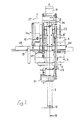
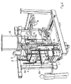
図4に示された型枠なし鋳型を作るための機械は、機械の他の要素を運ぶベース枠15を備えている。この機械は、上型型枠2と組合されたベアリング12を通してベース枠15に回転可能に取付けられた図1〜3に示された回転可能部分を含む。図4〜12では、枠15の一部は機械の必須部分を見ることが可能であるように切除されている。ピストンシリンダー装置13が枠15と上型型枠2と組合された連結点14との間に連結されており、ピストンシリンダー装置13のための連結点14は回転運動を提供するためにベアリング12から好適な距離に配置されている。
The machine for making the moldless mold shown in FIG. 4 comprises a
図3に最も良く示されるように、上型型枠2は案内棒7のための線状ベアリング20を備えており、従ってこの線状ベアリング20は上型型枠2の回転と共に回転する。案内棒7の上端に、ヨーク8が二つの案内棒の上端間に連結され、前記ヨーク8は加圧シリンダー9を支持し、そのピストン棒は砂鋳型を圧縮するために上型圧搾板5に連結されている。
As best shown in FIG. 3, the
下型型枠3が上型型枠2の下に配置され、線状ベアリング21により案内棒7に連結され、これらの案内棒7に沿った線状運動を可能にする。さらに、下型圧搾板6が、案内棒7に沿った線状運動のために1組の線状ベアリング22によりヨーク35に連結されている。
The lower mold 3 is arranged below the
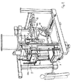
回転可能なシステムが図5に示されるように垂直位置にあるとき、一組のステー10(図1と3では一つのみ示されている)が図1と図3に示されるように配置される。この位置では、砂の圧縮は、上型圧搾板5を上型型枠2中にかつヨーク8と案内棒7を反対方向に動かす加圧シリンダー9により提供され、これによりステー10はヨーク11、及び下型圧搾板6のための線状ベアリング22上の対応する係合点と係合し、それにより下型圧搾板6を下型型枠3中に動かし、このようにして上型型枠2と下型型枠3の内側の砂をそれら二つの型枠間に挿入されたパターン板4の周りに圧縮する。
When the rotatable system is in a vertical position as shown in FIG. 5, a set of stays 10 (only one is shown in FIGS. 1 and 3) is arranged as shown in FIGS. The In this position, sand compression is provided by a pressure cylinder 9 which moves the
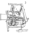
パターン板4は、上型型枠2と下型型枠3の間の空間内に及びその空間から外にパターン板4の水平運動を提供するためのレール28を含むパターン板移動機構19により動かされることができる。前記レール28はこの運動のためにピストンシリンダー装置26bに連結されており、前記パターン板移動機構19はさらに、案内棒27を介して上型型枠2に連結されており、パターン板移動機構19と上型型枠2間に連結されたピストンシリンダー装置26aによるパターン板の案内棒7に沿った方向への運動の可能性を提供する。パターン板移動機構19は上型型枠2と下型型枠3との間の空間内に及びその空間から外に動かされるときにパターン板4と係合しかつ支持するための及び上型型枠2と下型型枠3の間の所定位置に保持されるときにパターン板4との係合をはずすための好適な手段を含む。
The pattern plate 4 is moved by a pattern
下型圧搾板6は下型圧搾板のための線状ベアリング22に旋回機構を介して連結され、この旋回機構は、前記旋回運動がピストンシリンダー装置30により提供されるときにベアリング31上で旋回し、前記旋回運動は、下型圧搾板6を、下型型枠3と共働するための正常位置と、製造された型枠なし鋳型を成形機1から側方に排出するための図10と図11に示されるような位置との間で動かす。製造された型枠なし鋳型の排出は、水平位置と垂直位置の間でピストンシリンダー装置33により旋回されかつ成形機1の内側の位置と成形機1の外側の位置の間でピストンシリンダー装置34により移動可能な放出腕32を含む放出機構18により提供される。
The lower die
上型圧搾板5の上型型枠2に対する正しい配置は、上型型枠2とヨーク8の間に連結されたピストンシリンダー装置23により提供され、このようにして上型圧搾板5、ヨーク8及び案内棒7を上型型枠に対して配置する。従って、ピストンシリンダー装置24は上型型枠の配置のために上型型枠2と下型型枠3の間に連結され、ピストンシリンダー装置25はその配置のために上型型枠2と下型圧搾板6の間に連結される。
The correct arrangement of the
砂充填システム16は上型及び下型型枠内の砂充填開口29を通して砂を上型型枠2と下型型枠3の中に充填するために設けられ、前記砂充填開口29は図5に示されるように機械の回転可能部が垂直位置にあるときに砂充填システム16に連結される。
A
本発明による機械による二つの鋳型半分体を含む型枠なし鋳型を成形するための製造方法を以下に図4〜12を参照して説明するであろう。 A manufacturing method for molding an unframed mold comprising two mold halves by a machine according to the invention will be described below with reference to FIGS.
一連の操作は、水平位置の型枠を持ちかつ上型型枠2と下型型枠3の間に挿入されたパターン板4を持つ図4に示された状態で開始される。さらに、上型圧搾板5及び下型圧搾板6はそれぞれ上型型枠2及び下型型枠3内に挿入されており、従って型枠内に鋳型室を規定する。次の工程では、回転可能なシステムは、図5に示されるように、油圧シリンダー13により水平位置から垂直位置まで90°に渡って回転される。砂充填システム16は今やそれぞれの型枠の砂充填開口29に連結される。続く工程では、図5に示されるような位置のまま、上型型枠2及び下型型枠3の鋳型半分体形成空間は砂充填システム16からの砂供給により砂で充たされる。
A series of operations is started in a state shown in FIG. 4 having a horizontal form and having a pattern plate 4 inserted between the
次いで、充填された砂は、上型型枠2及び下型型枠3のそれぞれの中にさらに押しやられる上型圧搾板5及び下型圧搾板6により圧縮される。この圧縮は、先に述べたように、加圧シリンダー9により提供される。結果として、上型型枠2及び下型型枠3における圧縮により上型と下型が成形される。
Next, the filled sand is compressed by an upper
圧搾の完了後、機械の回転可能部は垂直位置からその開始位置に90°に渡って回転されて戻され、そこでは本質的に図4に示されるように上型型枠2と下型型枠3がそれらの水平位置をとる。次の工程では、下型型枠3と圧搾板6は一致して下に下げられ、パターン板4は、図6に示されるように、上型型枠2と下型型枠3の間の位置をとるように下げられ、下型型枠3上に載せながらパターン板移動機構19がパターン板4と係合するまで下げられることにより、パターン板4を上型型枠2から分離させ、パターン板4を下型型枠3から分離させる。次の工程では、パターン板4は上型型枠2と下型型枠3との間の空間から油圧シリンダー26bにより引っ込められ、油圧シリンダー26aにより図7に示された位置に上向きに動かされる。下型型枠3及び下型圧搾板6は下型型枠3の上面が上型型枠2の下面と接触するまで一致して上昇され、上型の鋳型表面が下型の鋳型表面と接触させられる。このようにして、上型と下型は図8に示されるように重ねられる。
After completion of the squeezing, the rotatable part of the machine is rotated back 90 ° from its vertical position to its starting position, where there is essentially an
その後、上型圧搾板5はピストンシリンダー装置23により下げられ、上型と下型を上型型枠2と下型型枠3から分離する。下型圧搾板6は同時にピストンシリンダー装置25により下げられ、下型圧搾板6は重ねられた上型と下型鋳型からなる鋳型パッケージ36のためのテーブルとしての役目をし、鋳型パッケージ36を図9に示されるような位置に下向きに動かす。
Thereafter, the upper
これに続いて、放出腕32がピストンシリンダー装置33により図10に示された位置に傾けられ、下型圧搾板6が図10に示された位置に回転される。前記回転は下型圧搾板6を下型圧搾板6と組合されたベアリング31周りに回転するピストンシリンダー装置30により提供される。この回転運動後に、放出腕32がピストンシリンダー装置33により図11に示された位置に回転して戻され、その結果として、ピストンシリンダー装置34が鋳型パッケージ36を図12に示されるように鋳型形成機の側方の所定位置に放出するように起動され、その位置で鋳型パッケージ36はこの目的のための別個の輸送システム上の注入装置上にさらに輸送されることができる。
Following this, the
これに続いてまたは次の鋳型の送出前の後の時点で、放出腕32はその開始位置に戻され、下型圧搾板6は下型型枠3と整合するように回転して戻され、その結果として下型型枠3は上型型枠2と下型型枠3との間へのパターン板4の挿入を可能にするように下げられ、その後、下型型枠3、下型圧搾板6及びパターン板4が成形機のための新しいサイクルの準備のできた図4に示される位置へもたらされる。
Following this, or at a later time before delivery of the next mold, the
成形機は今やその開始位置に到着し、型枠なし鋳型の大量生産のために繰返されるサイクル運転の一部として次の鋳型を製造するための準備が整う。 The molding machine has now arrived at its starting position and is ready to manufacture the next mold as part of a cycle operation that is repeated for mass production of moldless molds.
上述の実施態様は詳細に説明されたが、当業者は以下の特許請求項の範囲から逸脱することなくそれから幾つかの変更を提供することができるであろう。かかる変更は、例えばベアリング12の例えば下型型枠3と組合されるような代替位置、加圧シリンダー9の例えば下型圧搾板6に連結されるような代替位置、例えば油圧シリンダーまたは電気的線状駆動体のような種々の要素の相対運動を提供するための述べられた油圧シリンダー以外の移動機構の使用等を含む。
Although the above-described embodiments have been described in detail, those skilled in the art will be able to provide some modifications therefrom without departing from the scope of the following claims. Such a change is for example an alternative position of the
1 型枠なし鋳型を製造するための鋳型形成機
2 上型型枠
3 下型型枠
4 パターン板(嵌め合せ板)
5 上型圧搾板
6 下型圧搾板
7 案内棒
8 案内棒7を連結しかつ加圧シリンダー9を支持するヨーク
9 砂鋳型を圧縮するための加圧シリンダー
10 ステー
11 ステー10と係合するための案内棒7の両端のヨーク
12 回転可能システムの回転運動のためのベアリング
13 回転運動のためのピストンシリンダー装置
14 ピストンシリンダー装置13のための連結部
15 枠
16 砂充填システム
17 回転可能なシステムの回転運動のための軸
18 放出機構
19 パターン板移動機構
20 上型型枠のための線状ベアリング
21 下型型枠のための線状ベアリング
22 下型圧搾板のための線状ベアリング
23 上型圧搾板の相対運動のためのピストンシリンダー装置
24 下型型枠の相対運動のためのピストンシリンダー装置
25 下型圧搾板の相対運動のためのピストンシリンダー装置
26a パターン板の相対運動のためのピストンシリンダー装置
26b パターン板の相対運動のためのピストンシリンダー装置
27 パターン板移動機構19のための案内棒
28 パターン板移動機構19のためのレール
29 砂充填開口
30 下型圧搾板の回転運動のためのピストンシリンダー装置
31 下型圧搾板の回転運動のためのベアリング
32 放出腕
33 放出腕32を傾けるためのピストンシリンダー装置
34 製造された重ねられた上型と下型を放出するための放出腕32を移動するため
のピストンシリンダー装置
35 下型圧搾板6のためのヨーク
36 鋳型パッケージ
1 Molding machine for producing molds without
5 Upper
Claims (10)
下型型枠(3)と上型型枠(2)、
前記下型型枠(3)に挿入可能な下型圧搾板(6)、及び
前記上型型枠(2)に挿入可能な上型圧搾板(5)、
を含み、
これら全てが水平位置と垂直位置の間で回転されるように配置され、下型型枠(3)と上型型枠(2)が互いに向けてかつ互いから離れるように相対的に移動可能であるように配置されているものにおいて、
下型型枠(3)、上型型枠(2)、下型圧搾板(6)、及び上型圧搾板(5)が一組の共通の案内棒(7)によってそれらの相対的運動で案内されることを特徴とする成形機。A molding machine (1) for producing molds without formwork, which is:
Lower mold (3) and upper mold (2),
A lower mold pressing plate (6) that can be inserted into the lower mold frame (3), and an upper mold pressing plate (5) that can be inserted into the upper mold frame (2),
Including
All of them are arranged to be rotated between a horizontal position and a vertical position, and the lower mold frame (3) and the upper mold frame (2) are relatively movable so as to face each other and away from each other. In what is arranged,
Lower die mold (3), the upper mold mold (2), the lower mold squeeze plate (6), and the upper mold pressing plate (5) is a set of common guide rods (7) to thus their relative motion A molding machine characterized by being guided by.
Applications Claiming Priority (1)
| Application Number | Priority Date | Filing Date | Title |
|---|---|---|---|
| PCT/IB2007/001707 WO2009001150A1 (en) | 2007-06-25 | 2007-06-25 | Machine for producing flaskless moulds |
Publications (2)
| Publication Number | Publication Date |
|---|---|
| JP2010510889A JP2010510889A (en) | 2010-04-08 |
| JP5111515B2 true JP5111515B2 (en) | 2013-01-09 |
Family
ID=39165834
Family Applications (1)
| Application Number | Title | Priority Date | Filing Date |
|---|---|---|---|
| JP2009538799A Active JP5111515B2 (en) | 2007-06-25 | 2007-06-25 | Machine for making molds without formwork |
Country Status (8)
| Country | Link |
|---|---|
| US (1) | US7891404B2 (en) |
| EP (1) | EP2170542B1 (en) |
| JP (1) | JP5111515B2 (en) |
| CN (1) | CN101605620A (en) |
| DK (1) | DK2170542T3 (en) |
| ES (1) | ES2401655T3 (en) |
| PL (1) | PL2170542T3 (en) |
| WO (1) | WO2009001150A1 (en) |
Families Citing this family (3)
| Publication number | Priority date | Publication date | Assignee | Title |
|---|---|---|---|---|
| CN201677008U (en) * | 2010-02-24 | 2010-12-22 | 新东工业株式会社 | Casting and modeling device |
| CN102205393A (en) * | 2011-06-23 | 2011-10-05 | 江铃汽车股份有限公司 | Drawing guide rod and modeling template |
| CN107755646A (en) * | 2016-08-15 | 2018-03-06 | 科华控股股份有限公司 | A kind of Multi-point floating pressing device of shell mould die joint bonding contact |
Family Cites Families (2)
| Publication number | Priority date | Publication date | Assignee | Title |
|---|---|---|---|---|
| BR9917151A (en) * | 1999-02-23 | 2002-01-22 | Disa Ind As | Machine to produce molds without casting box |
| BRPI0611105B1 (en) * | 2005-06-07 | 2015-07-07 | Sintokogio Ltd | Blanking unit, unboxed blanking machine for shaping an upper and lower blanking box and blanking line to circulate a reuse blanking unit |
-
2007
- 2007-06-25 DK DK07789435.0T patent/DK2170542T3/en active
- 2007-06-25 US US12/445,488 patent/US7891404B2/en active Active
- 2007-06-25 CN CNA2007800421333A patent/CN101605620A/en active Pending
- 2007-06-25 WO PCT/IB2007/001707 patent/WO2009001150A1/en active Application Filing
- 2007-06-25 JP JP2009538799A patent/JP5111515B2/en active Active
- 2007-06-25 ES ES07789435T patent/ES2401655T3/en active Active
- 2007-06-25 EP EP07789435A patent/EP2170542B1/en active Active
- 2007-06-25 PL PL07789435T patent/PL2170542T3/en unknown
Also Published As
| Publication number | Publication date |
|---|---|
| WO2009001150A1 (en) | 2008-12-31 |
| PL2170542T3 (en) | 2013-07-31 |
| US7891404B2 (en) | 2011-02-22 |
| US20100096100A1 (en) | 2010-04-22 |
| JP2010510889A (en) | 2010-04-08 |
| CN101605620A (en) | 2009-12-16 |
| DK2170542T3 (en) | 2013-03-25 |
| EP2170542B1 (en) | 2013-01-02 |
| ES2401655T3 (en) | 2013-04-23 |
| EP2170542A1 (en) | 2010-04-07 |
Similar Documents
| Publication | Publication Date | Title |
|---|---|---|
| JP3628259B2 (en) | Machine for manufacturing unframed molds | |
| EP2195130B1 (en) | A core-setting apparatus used for a molding apparatus and a method for setting a core | |
| JP5111515B2 (en) | Machine for making molds without formwork | |
| JP4281799B2 (en) | Molding method and apparatus for upper and lower molds without casting frame | |
| JP4502077B2 (en) | Molding machine | |
| JP4645766B2 (en) | Frameless molding machine | |
| CN207578639U (en) | A kind of soft magnetic ferrite production molding machine | |
| CN110153368B (en) | System for progressively making and filling sand moulds in a mould string casting plant | |
| JP4310514B2 (en) | Mold making supply apparatus and method thereof | |
| US3878881A (en) | Method for producing and assembling cope and drag mold parts | |
| JPWO2005068107A1 (en) | Cast frame unit for molding machine and molding method using the same | |
| JP2798190B2 (en) | Frameless mold making equipment | |
| CN103752775A (en) | Machine for manufacturing sandbox-free sand mold | |
| EP1219830B1 (en) | Cam device for removing and tilting the front plate in a vertical mold casting machine | |
| JP4914920B2 (en) | Injection molding mechanism | |
| CN212331637U (en) | Multi-station injection mold | |
| CN214140847U (en) | Injection molding plastic reel for packaging electronic component | |
| JPH0130575B2 (en) | ||
| JP2736565B2 (en) | Frameless mold making equipment | |
| KR100509265B1 (en) | Powder molding method and rotary press apparatus used for same | |
| CN117161328A (en) | Vertical sand shooting double-station molding machine | |
| WO2012085621A1 (en) | A vertical sand moulding machine | |
| JPS62168640A (en) | Method for setting core for rotary type molding machine | |
| JPH0428525B2 (en) | ||
| SE455064B (en) | Machine for mould casting concrete products |
Legal Events
| Date | Code | Title | Description |
|---|---|---|---|
| A977 | Report on retrieval |
Free format text: JAPANESE INTERMEDIATE CODE: A971007 Effective date: 20120426 |
|
| A131 | Notification of reasons for refusal |
Free format text: JAPANESE INTERMEDIATE CODE: A131 Effective date: 20120508 |
|
| A521 | Request for written amendment filed |
Free format text: JAPANESE INTERMEDIATE CODE: A523 Effective date: 20120710 |
|
| A131 | Notification of reasons for refusal |
Free format text: JAPANESE INTERMEDIATE CODE: A131 Effective date: 20120911 |
|
| A521 | Request for written amendment filed |
Free format text: JAPANESE INTERMEDIATE CODE: A523 Effective date: 20120912 |
|
| TRDD | Decision of grant or rejection written | ||
| A01 | Written decision to grant a patent or to grant a registration (utility model) |
Free format text: JAPANESE INTERMEDIATE CODE: A01 Effective date: 20121005 |
|
| A01 | Written decision to grant a patent or to grant a registration (utility model) |
Free format text: JAPANESE INTERMEDIATE CODE: A01 |
|
| A61 | First payment of annual fees (during grant procedure) |
Free format text: JAPANESE INTERMEDIATE CODE: A61 Effective date: 20121009 |
|
| FPAY | Renewal fee payment (event date is renewal date of database) |
Free format text: PAYMENT UNTIL: 20151019 Year of fee payment: 3 |
|
| R150 | Certificate of patent or registration of utility model |
Ref document number: 5111515 Country of ref document: JP Free format text: JAPANESE INTERMEDIATE CODE: R150 Free format text: JAPANESE INTERMEDIATE CODE: R150 |
|
| R250 | Receipt of annual fees |
Free format text: JAPANESE INTERMEDIATE CODE: R250 |
|
| R250 | Receipt of annual fees |
Free format text: JAPANESE INTERMEDIATE CODE: R250 |
|
| R250 | Receipt of annual fees |
Free format text: JAPANESE INTERMEDIATE CODE: R250 |
|
| R250 | Receipt of annual fees |
Free format text: JAPANESE INTERMEDIATE CODE: R250 |
|
| R250 | Receipt of annual fees |
Free format text: JAPANESE INTERMEDIATE CODE: R250 |
|
| R250 | Receipt of annual fees |
Free format text: JAPANESE INTERMEDIATE CODE: R250 |
|
| R250 | Receipt of annual fees |
Free format text: JAPANESE INTERMEDIATE CODE: R250 |
|
| R250 | Receipt of annual fees |
Free format text: JAPANESE INTERMEDIATE CODE: R250 |
|
| R250 | Receipt of annual fees |
Free format text: JAPANESE INTERMEDIATE CODE: R250 |