JP4914920B2 - Injection molding mechanism - Google Patents
Injection molding mechanism Download PDFInfo
- Publication number
- JP4914920B2 JP4914920B2 JP2009518047A JP2009518047A JP4914920B2 JP 4914920 B2 JP4914920 B2 JP 4914920B2 JP 2009518047 A JP2009518047 A JP 2009518047A JP 2009518047 A JP2009518047 A JP 2009518047A JP 4914920 B2 JP4914920 B2 JP 4914920B2
- Authority
- JP
- Japan
- Prior art keywords
- mold
- injection molding
- molding mechanism
- mold part
- servo motor
- Prior art date
- Legal status (The legal status is an assumption and is not a legal conclusion. Google has not performed a legal analysis and makes no representation as to the accuracy of the status listed.)
- Active
Links
Images


Classifications
-
- B—PERFORMING OPERATIONS; TRANSPORTING
- B29—WORKING OF PLASTICS; WORKING OF SUBSTANCES IN A PLASTIC STATE IN GENERAL
- B29C—SHAPING OR JOINING OF PLASTICS; SHAPING OF MATERIAL IN A PLASTIC STATE, NOT OTHERWISE PROVIDED FOR; AFTER-TREATMENT OF THE SHAPED PRODUCTS, e.g. REPAIRING
- B29C45/00—Injection moulding, i.e. forcing the required volume of moulding material through a nozzle into a closed mould; Apparatus therefor
- B29C45/17—Component parts, details or accessories; Auxiliary operations
- B29C45/64—Mould opening, closing or clamping devices
- B29C45/66—Mould opening, closing or clamping devices mechanical
- B29C45/661—Mould opening, closing or clamping devices mechanical using a toggle mechanism for mould clamping
-
- B—PERFORMING OPERATIONS; TRANSPORTING
- B29—WORKING OF PLASTICS; WORKING OF SUBSTANCES IN A PLASTIC STATE IN GENERAL
- B29C—SHAPING OR JOINING OF PLASTICS; SHAPING OF MATERIAL IN A PLASTIC STATE, NOT OTHERWISE PROVIDED FOR; AFTER-TREATMENT OF THE SHAPED PRODUCTS, e.g. REPAIRING
- B29C45/00—Injection moulding, i.e. forcing the required volume of moulding material through a nozzle into a closed mould; Apparatus therefor
- B29C45/14—Injection moulding, i.e. forcing the required volume of moulding material through a nozzle into a closed mould; Apparatus therefor incorporating preformed parts or layers, e.g. injection moulding around inserts or for coating articles
- B29C45/14467—Joining articles or parts of a single article
-
- B—PERFORMING OPERATIONS; TRANSPORTING
- B29—WORKING OF PLASTICS; WORKING OF SUBSTANCES IN A PLASTIC STATE IN GENERAL
- B29C—SHAPING OR JOINING OF PLASTICS; SHAPING OF MATERIAL IN A PLASTIC STATE, NOT OTHERWISE PROVIDED FOR; AFTER-TREATMENT OF THE SHAPED PRODUCTS, e.g. REPAIRING
- B29C45/00—Injection moulding, i.e. forcing the required volume of moulding material through a nozzle into a closed mould; Apparatus therefor
- B29C45/17—Component parts, details or accessories; Auxiliary operations
- B29C45/46—Means for plasticising or homogenising the moulding material or forcing it into the mould
- B29C45/56—Means for plasticising or homogenising the moulding material or forcing it into the mould using mould parts movable during or after injection, e.g. injection-compression moulding
- B29C45/561—Injection-compression moulding
-
- B—PERFORMING OPERATIONS; TRANSPORTING
- B29—WORKING OF PLASTICS; WORKING OF SUBSTANCES IN A PLASTIC STATE IN GENERAL
- B29C—SHAPING OR JOINING OF PLASTICS; SHAPING OF MATERIAL IN A PLASTIC STATE, NOT OTHERWISE PROVIDED FOR; AFTER-TREATMENT OF THE SHAPED PRODUCTS, e.g. REPAIRING
- B29C45/00—Injection moulding, i.e. forcing the required volume of moulding material through a nozzle into a closed mould; Apparatus therefor
- B29C45/17—Component parts, details or accessories; Auxiliary operations
- B29C2045/1784—Component parts, details or accessories not otherwise provided for; Auxiliary operations not otherwise provided for
- B29C2045/1792—Machine parts driven by an electric motor, e.g. electric servomotor
-
- B—PERFORMING OPERATIONS; TRANSPORTING
- B29—WORKING OF PLASTICS; WORKING OF SUBSTANCES IN A PLASTIC STATE IN GENERAL
- B29C—SHAPING OR JOINING OF PLASTICS; SHAPING OF MATERIAL IN A PLASTIC STATE, NOT OTHERWISE PROVIDED FOR; AFTER-TREATMENT OF THE SHAPED PRODUCTS, e.g. REPAIRING
- B29C45/00—Injection moulding, i.e. forcing the required volume of moulding material through a nozzle into a closed mould; Apparatus therefor
- B29C45/17—Component parts, details or accessories; Auxiliary operations
- B29C45/46—Means for plasticising or homogenising the moulding material or forcing it into the mould
- B29C45/56—Means for plasticising or homogenising the moulding material or forcing it into the mould using mould parts movable during or after injection, e.g. injection-compression moulding
- B29C45/561—Injection-compression moulding
- B29C2045/564—Compression drive means acting independently from the mould closing and clamping means
-
- B—PERFORMING OPERATIONS; TRANSPORTING
- B29—WORKING OF PLASTICS; WORKING OF SUBSTANCES IN A PLASTIC STATE IN GENERAL
- B29C—SHAPING OR JOINING OF PLASTICS; SHAPING OF MATERIAL IN A PLASTIC STATE, NOT OTHERWISE PROVIDED FOR; AFTER-TREATMENT OF THE SHAPED PRODUCTS, e.g. REPAIRING
- B29C45/00—Injection moulding, i.e. forcing the required volume of moulding material through a nozzle into a closed mould; Apparatus therefor
- B29C45/17—Component parts, details or accessories; Auxiliary operations
- B29C45/64—Mould opening, closing or clamping devices
- B29C45/66—Mould opening, closing or clamping devices mechanical
- B29C2045/667—Cam drive for mould closing or clamping
-
- B—PERFORMING OPERATIONS; TRANSPORTING
- B29—WORKING OF PLASTICS; WORKING OF SUBSTANCES IN A PLASTIC STATE IN GENERAL
- B29L—INDEXING SCHEME ASSOCIATED WITH SUBCLASS B29C, RELATING TO PARTICULAR ARTICLES
- B29L2031/00—Other particular articles
- B29L2031/712—Containers; Packaging elements or accessories, Packages
Description
本発明は、射出成形機構に関する。この射出成形機構は、ラミネート紙のスリーブの縁部における熱可塑性の上部の成形のために開発された。 The present invention relates to an injection molding mechanism. This injection molding mechanism was developed for the molding of a thermoplastic top at the edge of a laminated paper sleeve.
本発明は、射出圧縮として知られている射出成形技術に使用するために開発されている。射出圧縮では、第1の段階で、部分的に閉じられた金型が部分的に満たされる。次いで、金型は、完全に閉じられ、金型内部の材料に圧縮力を与え、この圧縮により、材料が金型を完全に満たすことになる。金型を閉じ圧縮力を与える作動は、しばしば、油圧式シリンダ及びいくつかの種類のリンク機構によって実施される。1つの知られている装置では、リンク・システムに真直ぐな向きが与えられている限りにおいて、圧縮力を与える第2の段階が実施される。実際、従来使用されている機構は、正確に制御することが困難であり、場合によっては、適切な圧縮というよりは変形に対する潜在的リスクが示されている。 The present invention has been developed for use in an injection molding technique known as injection compression. In injection compression, in a first stage, a partially closed mold is partially filled. The mold is then completely closed, applying a compressive force to the material inside the mold, which causes the material to completely fill the mold. The operation of closing the mold and applying a compressive force is often performed by hydraulic cylinders and some types of linkages. In one known device, a second stage of applying compressive force is performed as long as the link system is given a straight orientation. In fact, the mechanisms used in the past are difficult to control precisely, and in some cases, a potential risk for deformation rather than proper compression has been shown.
本発明の1つの目的は、第1の段階で部分的に閉じられた金型、第2の段階で閉じられた金型及び圧縮力を与える、簡易であるが信頼性の高い機構を得ることである。さらに、機構は、厳密に制御することが可能でなければならない。別の目的は、同じ結果をもたらす反復可能なプロセスを有することである。さらに別の目的は、1つの構成要素を製造するためのサイクル時間が、比較的短いものでなければならないということである。 One object of the present invention is to obtain a simple but reliable mechanism that provides a mold partially closed in the first stage, a mold closed in the second stage and a compression force. It is. Furthermore, the mechanism must be able to be tightly controlled. Another object is to have a repeatable process that yields the same result. Yet another object is that the cycle time for manufacturing one component must be relatively short.
上記の目的は、押出機と、内側金型部分と、外側金型部分とを含む射出成形機構によって達成される。射出成形機構は、金型を部分的に閉じるための第1の機構と、金型を閉じて、押し出された材料を金型の内部で圧縮するための第2の機構とをさらに含む。金型部分の一方は、金型空洞を形成するために他方の金型部分に向って移動可能に構成されている。金型部分の少なくとも一方は、金型空洞内に開口して押出機に連結されたチャネル(通路)を有する。金型を部分的に閉じるための第1の機構は、サーボモータによって駆動されるひざ型機構(knee mechanism)を有する。金型を閉じて、押し出された材料をその金型の内部で圧縮するための第2の機構は、第2のサーボモータのシャフトの一部分である偏心輪(eccentric)を有する。 The above objective is accomplished by an injection molding mechanism that includes an extruder, an inner mold part, and an outer mold part. The injection molding mechanism further includes a first mechanism for partially closing the mold and a second mechanism for closing the mold and compressing the extruded material within the mold. One of the mold parts is configured to be movable toward the other mold part to form a mold cavity. At least one of the mold parts has a channel (passage) that opens into the mold cavity and is connected to the extruder. The first mechanism for partially closing the mold has a knee mechanism driven by a servo motor. A second mechanism for closing the mold and compressing the extruded material within the mold has an eccentric that is part of the shaft of the second servomotor.
サーボモータを使用することにより、正確な制御を有することが可能になる。というのも、サーボモータは、それ自体が正確に制御可能であるためである。サーボモータの相対的に大きな回転によって偏心輪の小さな移動がもたらされるため、正確な制御の可能性がさらに高められる。サーボモータはまた、各々特有のケースで必要とされる所望の移動を正確に与えるのを容易にする。必要とされる移動は、たとえば様々なセンサによって監視され得る。さらに、機構の固有の弾性が、使用された圧縮力の部分を吸収するのを助ける。 By using a servo motor, it is possible to have accurate control. This is because the servo motor itself can be accurately controlled. The relatively large rotation of the servo motor results in a small movement of the eccentric wheel, further increasing the possibility of accurate control. Servo motors also facilitate accurately providing the desired movement required in each particular case. The required movement can be monitored by various sensors, for example. In addition, the inherent elasticity of the mechanism helps absorb the portion of compression force used.
本発明のさらなる目的及び利点は、現在好ましい実施例の以下の詳細な説明を読むと、当業者に明確になるであろう。 Further objects and advantages of the present invention will become apparent to those of ordinary skill in the art upon reading the following detailed description of the presently preferred embodiments.
本発明は、例を用い、添付の概略図を参照して以下でさらに説明される。 The invention is further described below by way of example and with reference to the accompanying schematic drawings.
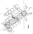
図に示される機構は、内側金型部分1及び外側金型部分2を有する金型を有する。外側金型部分2は、押し出されたプラスチック材料を受けるための1つ又は複数のチャネル3を有しており、内側金型部分1に関して移動可能に構成されている。図示される実施例では、内側金型部分1は、5つのマンドレルを有するマンドレル・ホイール4上に配置されたマンドレル形状を有する。他の実施例では、他の数のマンドレルをマンドレル・ホイール上に配置させることができる。マンドレルは、マンドレル・ホイール4上に径方向に外側に突出して配置される。マンドレル・ホイール4は、マンドレルが外側金型部分2に向かい合った正しい位置に1つずつ配置されるようにシャフト上で間欠的に回転するように設けられている。
The mechanism shown in the figure has a mold having an inner mold part 1 and an
図2の実施例では、次の段階において、ラミネート紙のスリーブ5が、キャップ6と一緒にマンドレル上に配置され、このマンドレルは内側金型部分1を形成している。次いで、内側金型部分1が、外側金型部分2と同一直線上に配置される。内側及び外側金型部分1、2は、互いに接合し(図1を参照)、金型空洞7がそれらの間に形成される。外側金型部分2の(1つ又は複数の)チャネル3は、金型空洞7内に開口している。
In the embodiment of FIG. 2, in the next stage, a laminated
図2では、外側金型部分2が、複数のロッド10によって互いに保持された下側プレート8及び上側プレート9を有する移動可能な枠上に取り付けられている。プレート8、9は、射出成形機構の諸部分に余地を与えるために互いからある距離を離して配置される。外側金型部分2は、下側プレート8上に取り付けられる。下側及び上側プレート8、9並びにロッド10から形成された枠は、レール11上に移動可能に構成される。
In FIG. 2, the
レール11の上部には、第1のサーボモータ13及び第2のサーボモータ14を保持する支持体12が固定される。第1の枢動可能なアーム15が、ディスク17の回転軸からある距離を離して配置されているためにディスク17上に偏心して配置された第1の枢軸16によってサーボモータに連結される。ディスク17は、第1のサーボモータ13によって回転される。第1の枢動可能なアーム15は、第2の枢軸19によって第2の枢動可能なアーム18に連結される。第2の枢動可能なアーム18は、第3の枢軸20によって外側金型部分2の枠の上側プレート9に連結される。
A
第3の枢動可能なアーム21は、一方の端部において、第1及び第2の枢動可能なアーム15、18と同じ枢軸19に連結される。第3の枢動可能なアーム21の他方の端部は、第2のサーボモータ14で受けられる。
The third
第1のサーボモータ13の開始位置において、すなわち第1のサーボモータ13の回転前、第2の枢動可能なアーム18は、想像線22に関して傾斜している(図2を参照)。想像線22は、金型の中央を通り抜け、第2の枢動可能なアーム18と枠の上側プレート9の間の枢軸20を横切り、第2のサーボモータ14のシャフト及び偏心輪を横切り、且つマンドレル・ホイール4の中央を通り抜けている。第1のサーボモータ13が、金型が部分的に閉じられたその最終位置まで回転したとき(図3を参照)、第2の枢動可能なアーム18は、第1、第2、及び第3の枢動アーム15、18、21並びに第1、第2、及び第3の枢軸16、19、20の配置により、想像線22と同一線上になる位置まで移動されている。第3の枢動可能なアーム21は、第1のサーボモータ13がその最終位置に到達したとき、第2の枢動可能なアーム18及び想像線22と同一線上になるように配置される。
At the starting position of the
第2のサーボモータ14には、第3の枢動可能なアーム21上で機能する偏心輪が装着される。偏心輪は、第2のサーボモータ14の回転軸上に形成され、第3の枢動可能なアーム21は、ローラ軸受けにジャーナル支承されて受けられる。第2のサーボモータ14は、第1のサーボモータ13がその最終位置に到達して初めて駆動されるので、第2のサーボモータ14の偏心輪は直線のリンク機構上で機能することになる。
An eccentric wheel that functions on the third
したがって、第1のサーボモータ13は、第1、第2、及び第3の枢動可能なアーム15、18、21の形態のひざ型機構と協働して金型を部分的に閉じる。第2のサーボモータ14は、偏心輪及び第2及び第3の枢動可能なアーム18、21と協働して金型を閉じ高いクランプ力でそれをロックし、プラスチック材料を金型の内部で圧縮する。
Accordingly, the
押出機23が、射出圧縮機構に配置される。管24が、プラスチック材料を押出機から外側金型部分2の(1つ又は複数の)チャネル3を介して外側と内側の金型部分2、1の間に形成された金型空洞7内に導くように敷設される。
An
添付された図に示された実施例は、次の作動サイクルを有する。マンドレル・ホイール4は、各々が内側金型部分1を形成する、等間隔に離間された5つのマンドレルを有する。マンドレル・ホイール4は、各々の作動サイクル時、フル回転の5分の1の位置に回転され、又は位置合わせされる。したがって、各々のマンドレルは、連続的に5つの異なる位置を占めることになる。第1の位置では、スリーブ5が、マンドレル上に配置される。第2の位置では、キャップ6が、マンドレル上に配置される。第3の位置では、プラスチック製の上部が、スリーブ5とキャップ6の間に成形される。したがって、その位置を過ぎると、スリーブ、プラスチック製の上部、及びキャップ6は1つのユニットを形成する。マンドレルの第4の位置では、形成されたユニットが冷却される。第5及び最後の位置では、形成されたユニットが、マンドレルから取り外される。マンドレル上における諸部品の配置及び最終製品の取り外しは、通常、自動的に行われる。しかし、当業者は、それを少なくとも部分的に手動で実施することができることも認識している。この部分は本発明には何ら重要性を有さないので、本明細書ではこれ以上説明されない。
The embodiment shown in the attached figures has the following operating cycle. The mandrel wheel 4 has five equally spaced mandrels, each forming an inner mold part 1. The mandrel wheel 4 is rotated or aligned to a position that is one fifth of full rotation during each operating cycle. Thus, each mandrel will occupy five different positions in succession. In the first position, the
作動サイクルの開始時、1つのマンドレル、すなわち内側金型部分1は、外側金型部分2と一直線上に配置されている。内側金型部分1は、スリーブ5及びキャップ6を保持している。次いで、第1のサーボモータ13は、外側金型部分2が内側金型部分1に向って下方に移動されるため、金型を閉じ、それによって金型空洞7が形成される。第1のサーボモータ13の回転が、第1の枢動可能なアーム15が連結された枢軸16を保持するディスク17を回転させる。第1の枢動可能なアーム15の移動により、第2及び第3の移動可能なアーム18、21もまた移動される。第1のサーボモータ13は、第2及び第3のアーム18、21を、前記アーム18、21が想像線22と一直線上になる直線を形成する位置に移動させる。その位置において、第1のサーボモータ13は停止され、第1のサーボモータ13の最終位置がもたらされる。(図3を参照)。
At the start of the operating cycle, one mandrel, i.e. the inner mold part 1, is arranged in line with the
作動サイクルの次の段階は、押出機23が管24及び外側金型部分2のチャネル3を介してプラスチック材料を金型空洞7内に射出することである。射出されたプラスチック材料は、金型空洞7を完全には満たさない。次いで、第2のサーボモータ14が回転し、それによって第2のサーボモータ14に連結された偏心輪は、第3の枢動可能なアーム21上で、外側金型部分2が内側金型部分1に向ってさらに移動され金型を閉じるように機能する(図4を参照)。第2のサーボモータ14は、フル回転の約3分の1から2分の1を回転することになる。第2のサーボモータ14のこの比較的長い回転は、偏心輪による1〜2mmだけの外側金型部分の移動になる。外側金型部分2のこのさらなる移動により、射出されたプラスチック材料は、金型空洞7を埋めるように圧縮される。サーボモータ13、14の両方が最終位置にある状態では、射出された材料が冷却される。したがって、冷却は、圧縮の下で行われ、通常は金型の内側から行われる。
The next stage of the operating cycle is that the
冷却後、外側金型部分2が少なくとも第1のサーボモータ13によって内側金型部分1から持ち上げられるため、金型が開かれる。通常、第1及び第2のサーボモータ13、14は、同時に回転する。両方のサーボモータ13、14がその開始位置に戻るとき、マンドレル・ホイール4は、フル回転の5分の1に位置合わせされる。この時、新しい作動サイクルが開始され得る。
After cooling, the
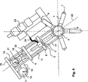
図5では、本発明の別の実施例が示され、この場合、射出成形機構は、基部25に固定されたレール11上に移動可能に取り付けられている。この基部25は、中央ハブに取り付けられたマンドレル・ホイール近傍に位置している。射出成形機構は、図5に示されるように上端部において、ひざ型機構18、21を介して支持体12に取り付けられている。レールは、100〜120cm程度の比較的長いものであり、わずかに可撓性を有するように形成される。通常の作動時、ひざ型機構からレールにかかる力は、約50〜100kNである。これらの負荷時、レールは、約0.05〜0.1パーセント屈曲するように設計されるべきであり、これは、100cmの長さのレールに対して0.5mm〜1mmとなる。これは、金型を約1mm圧縮するには、ひざ型機構は、レールの屈曲のために約1.5〜2.0mm延伸されねばならないことを意味する。前記屈曲によって金型の過剰充填が相殺されるため、レール11の屈曲により、射出成形機構の設定が一層容易になる。レール11は、外端部が支持体12に剛性に取り付けられ、内端部が基部25に剛性に取り付けられる。
In FIG. 5, another embodiment of the invention is shown, in which the injection molding mechanism is movably mounted on a
レール11の屈曲のさらなる利点は、金型1、2内の射出されたプラスチック材料が冷却されたときに明らかになる。続いて、プラスチック材料は、収縮し、従来の成形機構の壁から分離する。しかし、レール11の屈曲により、冷却時、金型1、2が射出されたプラスチック材料に常に接触していることが確保される。これはまた、冷却の速度も上昇させる。というのは、金型は、プラスチックの細部全体に接触している場合、プラスチック材料からの熱をより効率的に伝えるためである。
A further advantage of the bending of the
長く、比較的細いレール11は、射出成形機構に別の利点を与える。外側金型部分2は、レール11の長手方向の屈曲によってもたらされる長手方向に加えて、横方向にわずかに移動可能である。この横方向の移動は、レール11の撓みによって可能である。横方向の移動は、金型1、2内の力平衡に合わせられるため、外側金型2を自己整合させる。射出されたプラスチック材料が、金型のジャケット26上の2箇所以上の位置において、十分に開いている金型1、2に流入する圧縮成形時(図1を参照)、金型の圧縮が、力平衡を創出し、この力平衡は、最終のプラスチック部分の厚さが、様々な位置で射出された量が異なっているにもかかわらずある程度均一になることを保証しようとするものである。これは、金型部分1、2が、横方向にわずかに移動して、前記力平衡に合わせることができるように配置される場合に可能である。これは、外側金型部分2を可撓製のレール11上に吊設された機構に配置することによって可能になる。内側金型部分1は、マンドレル・ホイール4に連結され、ある程度固定されたものである。射出成形機構が射出圧縮成形の垂直抗力を受けるとき、射出成形機構、したがって外側金型の最大可能な横方向の移動は、(上記で説明されたレール11の長さの0.05〜0.1%に相当する)0.5〜1mm程度になるはずである。上記の屈曲は、外側金型部分2が、横方向に約0.5〜1mmの距離を移動することができるようにレール11上に吊設された射出成形機構に取り付けられる位置を示す。
The long and relatively
長手方向の屈曲及び横方向の屈曲は、特有の用途に適合されねばならない。上記のケースでは、屈曲は、第2の偏心輪機構によってもたらされる移動に比べて、約半分の距離であり、すなわち、偏心輪機構14によって長手方向にもたらされる移動が約1mmである場合、長手方向の屈曲は約0.5mmになる。射出圧縮機構の長手方向の移動及びレール11の同じ方向の屈曲の間の他の関係も可能である。同じことが、レール11の横方向の屈曲にもあてはまる。
The longitudinal and lateral bends must be adapted to the specific application. In the above case, the bend is about half the distance compared to the movement provided by the second eccentric ring mechanism, i.e. if the movement provided in the longitudinal direction by the
サーボモータ13、14、リンク・システム15、18、21、及び外側金型部分2を担持する部分の正確な形態及び設計は、意図する機能を実行する限り、変更することができることを当業者は認識している。
Those skilled in the art will appreciate that the exact form and design of the
Claims (9)
前記ひざ型機構が、第1、第2及び第3の枢動可能なアーム(15、18、21)から形成され、前記第1の枢動可能なアーム(15)が、一方の端部において、前記第1のサーボモータ(13)によって回転されるディスク(17)に第1の枢軸(16)によって連結され、他方の端部において、前記第2の枢動可能なアーム(18)の一方の端部に第2の枢軸(19)によって連結され、前記第2の枢動可能なアーム(18)が、その他方の端部において、前記外側金型部分(2)を担持する枠に第3の枢軸(20)によって連結されており、前記第3の枢動可能なアーム(21)が、一方の端部において、前記第2の枢軸(19)に連結され、また前記第1と第2の枢動可能なアーム(15、18)も連結させており、他方の端部において、前記第2のサーボモータ(14)のシャフトに連結されていることを特徴とする射出成形機構。An extruder (23), a mold having an inner mold part (1) and an outer mold part (2) , a first mechanism for partially closing the mold, and closing the mold the extruded material and a second mechanism for compressing inside of the mold, one mold part (2) comprises a mold cavity between the two mold parts (1, 2) (7) is configured to be movable toward the other mold part (1), and one mold part (2) opens into the mold cavity (7) and is An injection molding mechanism having one or more channels (3) connected to an extruder (23), wherein the first mechanism for partially closing the mold comprises a first servo motor ( 13) having a knee-shaped mechanism driven by the above-mentioned method for closing the mold and compressing the extruded material inside the mold 2 mechanisms, have a eccentric which is part of the shaft of the second servo motor (14),
The knee mechanism is formed from first, second and third pivotable arms (15, 18, 21), the first pivotable arm (15) being at one end. , Connected to a disk (17) rotated by the first servo motor (13) by a first pivot (16) and at the other end one of the second pivotable arms (18). The second pivotable arm (18) is connected to the end of the second pivot shaft (19), and the second pivotable arm (18) is connected to the frame carrying the outer mold part (2) at the other end. Three pivots (20), the third pivotable arm (21) is connected at one end to the second pivot (19), and the first and first pivots (21). Two pivotable arms (15, 18) are also connected and connected to the other end. Te, injection molding mechanism, characterized in that it is connected to the second shaft of the servo motor (14).
Applications Claiming Priority (3)
| Application Number | Priority Date | Filing Date | Title |
|---|---|---|---|
| SE0601470 | 2006-07-05 | ||
| SE0601470-8 | 2006-07-05 | ||
| PCT/SE2007/000638 WO2008004939A1 (en) | 2006-07-05 | 2007-07-02 | Injection moulding mechanism |
Publications (2)
| Publication Number | Publication Date |
|---|---|
| JP2009542469A JP2009542469A (en) | 2009-12-03 |
| JP4914920B2 true JP4914920B2 (en) | 2012-04-11 |
Family
ID=38894818
Family Applications (1)
| Application Number | Title | Priority Date | Filing Date |
|---|---|---|---|
| JP2009518047A Active JP4914920B2 (en) | 2006-07-05 | 2007-07-02 | Injection molding mechanism |
Country Status (8)
| Country | Link |
|---|---|
| EP (1) | EP2040901B1 (en) |
| JP (1) | JP4914920B2 (en) |
| BR (1) | BRPI0713271B1 (en) |
| ES (1) | ES2488917T3 (en) |
| MX (1) | MX2008016421A (en) |
| RU (1) | RU2429125C2 (en) |
| TW (1) | TWI411514B (en) |
| WO (1) | WO2008004939A1 (en) |
Families Citing this family (2)
| Publication number | Priority date | Publication date | Assignee | Title |
|---|---|---|---|---|
| US8616400B2 (en) | 2009-12-14 | 2013-12-31 | Tetra Laval Holdings & Finance S.A. | Opening device and method for manufacturing the same, and a packaging container provided with said opening device |
| US9505519B2 (en) | 2009-12-14 | 2016-11-29 | Tetra Laval Holdings & Finance S.A. | Opening device and method for manufacturing the same, and a packaging material provided with said opening device |
Family Cites Families (8)
| Publication number | Priority date | Publication date | Assignee | Title |
|---|---|---|---|---|
| US3830614A (en) * | 1972-12-01 | 1974-08-20 | A Kurtz | Injection molding machine |
| US4828769A (en) * | 1986-05-05 | 1989-05-09 | Galic/Maus Ventures | Method for injection molding articles |
| JP3598259B2 (en) * | 2000-06-29 | 2004-12-08 | 東芝機械株式会社 | Mold clamping device |
| JP3731083B2 (en) * | 2000-10-05 | 2006-01-05 | 有限会社 テクノクリエイト | Resin sealing device |
| SG98439A1 (en) * | 2001-01-09 | 2003-09-19 | Hongguan Technologies S Pte Lt | Apparatus for and a method used in compressing a workpiece |
| JP4199732B2 (en) * | 2002-09-20 | 2008-12-17 | バイオニクス株式会社 | Press mechanism |
| TWI280166B (en) * | 2002-12-26 | 2007-05-01 | Toshiba Machine Co Ltd | Liquid material feed apparatus of die casting machine, liquid material feed method, and ladle |
| ATE501827T1 (en) * | 2004-07-26 | 2011-04-15 | Sumitomo Heavy Industries | INJECTION DEVICE |
-
2007
- 2007-07-02 MX MX2008016421A patent/MX2008016421A/en active IP Right Grant
- 2007-07-02 BR BRPI0713271A patent/BRPI0713271B1/en not_active IP Right Cessation
- 2007-07-02 WO PCT/SE2007/000638 patent/WO2008004939A1/en active Application Filing
- 2007-07-02 EP EP07748297.4A patent/EP2040901B1/en active Active
- 2007-07-02 RU RU2009103778/05A patent/RU2429125C2/en active
- 2007-07-02 JP JP2009518047A patent/JP4914920B2/en active Active
- 2007-07-02 ES ES07748297.4T patent/ES2488917T3/en active Active
- 2007-07-05 TW TW096124405A patent/TWI411514B/en active
Also Published As
| Publication number | Publication date |
|---|---|
| RU2429125C2 (en) | 2011-09-20 |
| JP2009542469A (en) | 2009-12-03 |
| TW200819276A (en) | 2008-05-01 |
| EP2040901B1 (en) | 2014-06-18 |
| RU2009103778A (en) | 2010-08-10 |
| EP2040901A4 (en) | 2013-02-27 |
| MX2008016421A (en) | 2009-01-21 |
| TWI411514B (en) | 2013-10-11 |
| BRPI0713271B1 (en) | 2018-05-08 |
| EP2040901A1 (en) | 2009-04-01 |
| BRPI0713271A2 (en) | 2012-04-10 |
| WO2008004939A1 (en) | 2008-01-10 |
| ES2488917T3 (en) | 2014-09-01 |
Similar Documents
| Publication | Publication Date | Title |
|---|---|---|
| EP2189264B1 (en) | Ultrasonic device for moulding micro plastic parts | |
| JPH10225978A (en) | Rotary blow molder | |
| JP2009536113A (en) | Injection molding equipment for manufacturing irregularly shaped elongated parts | |
| JP4914920B2 (en) | Injection molding mechanism | |
| US3270117A (en) | Apparatus and method for producing a precision rubber tube | |
| CN103213251B (en) | Injection mold of medical intervention catheter adapter | |
| JP5880354B2 (en) | Insert molding method | |
| CN104842498B (en) | Injection device | |
| WO1998038023A1 (en) | Blow molding machine | |
| EP0284242A2 (en) | Rotary blow molding machine | |
| KR101774116B1 (en) | Mold apparatus for forming composite sheet | |
| CN214726241U (en) | Aluminum alloy adds silica gel forming die | |
| CN102149530A (en) | Apparatus and method for controlling injection compression moulding | |
| JP5111515B2 (en) | Machine for making molds without formwork | |
| JP3793072B2 (en) | Preform molding method and apparatus | |
| JP5336264B2 (en) | Blow molding die and blow molding method | |
| WO2008033025A2 (en) | Apparatus and method for the manufacture of products | |
| JP6841407B2 (en) | Injection molding rotary mold | |
| JP3619487B2 (en) | Split mold opening and closing device for intermediate mold in injection blow molding machine | |
| JP4034004B2 (en) | Core pin cooling device | |
| CN114872284B (en) | Injection molding system and injection molding method | |
| CN103707456A (en) | Ejection mechanism | |
| CN206899684U (en) | Injection mold die opening mechanism | |
| CN105269749A (en) | Vertical injection molding machine or injection molding machine | |
| KR100436798B1 (en) | Piping system of a blow molding |
Legal Events
| Date | Code | Title | Description |
|---|---|---|---|
| A621 | Written request for application examination |
Free format text: JAPANESE INTERMEDIATE CODE: A621 Effective date: 20100312 |
|
| A977 | Report on retrieval |
Free format text: JAPANESE INTERMEDIATE CODE: A971007 Effective date: 20110920 |
|
| A131 | Notification of reasons for refusal |
Free format text: JAPANESE INTERMEDIATE CODE: A131 Effective date: 20110927 |
|
| A521 | Request for written amendment filed |
Free format text: JAPANESE INTERMEDIATE CODE: A523 Effective date: 20111219 |
|
| TRDD | Decision of grant or rejection written | ||
| A01 | Written decision to grant a patent or to grant a registration (utility model) |
Free format text: JAPANESE INTERMEDIATE CODE: A01 Effective date: 20120117 |
|
| A01 | Written decision to grant a patent or to grant a registration (utility model) |
Free format text: JAPANESE INTERMEDIATE CODE: A01 |
|
| A61 | First payment of annual fees (during grant procedure) |
Free format text: JAPANESE INTERMEDIATE CODE: A61 Effective date: 20120123 |
|
| R150 | Certificate of patent or registration of utility model |
Ref document number: 4914920 Country of ref document: JP Free format text: JAPANESE INTERMEDIATE CODE: R150 Free format text: JAPANESE INTERMEDIATE CODE: R150 |
|
| FPAY | Renewal fee payment (event date is renewal date of database) |
Free format text: PAYMENT UNTIL: 20150127 Year of fee payment: 3 |
|
| R250 | Receipt of annual fees |
Free format text: JAPANESE INTERMEDIATE CODE: R250 |
|
| R250 | Receipt of annual fees |
Free format text: JAPANESE INTERMEDIATE CODE: R250 |
|
| R250 | Receipt of annual fees |
Free format text: JAPANESE INTERMEDIATE CODE: R250 |
|
| R250 | Receipt of annual fees |
Free format text: JAPANESE INTERMEDIATE CODE: R250 |
|
| R250 | Receipt of annual fees |
Free format text: JAPANESE INTERMEDIATE CODE: R250 |
|
| R250 | Receipt of annual fees |
Free format text: JAPANESE INTERMEDIATE CODE: R250 |
|
| R250 | Receipt of annual fees |
Free format text: JAPANESE INTERMEDIATE CODE: R250 |
|
| R250 | Receipt of annual fees |
Free format text: JAPANESE INTERMEDIATE CODE: R250 |
|
| R250 | Receipt of annual fees |
Free format text: JAPANESE INTERMEDIATE CODE: R250 |