JP5106612B2 - Operating device and method and program thereof - Google Patents
Operating device and method and program thereof Download PDFInfo
- Publication number
- JP5106612B2 JP5106612B2 JP2010233776A JP2010233776A JP5106612B2 JP 5106612 B2 JP5106612 B2 JP 5106612B2 JP 2010233776 A JP2010233776 A JP 2010233776A JP 2010233776 A JP2010233776 A JP 2010233776A JP 5106612 B2 JP5106612 B2 JP 5106612B2
- Authority
- JP
- Japan
- Prior art keywords
- instruction
- movement
- point
- designated
- change
- Prior art date
- Legal status (The legal status is an assumption and is not a legal conclusion. Google has not performed a legal analysis and makes no representation as to the accuracy of the status listed.)
- Expired - Fee Related
Links
Images


Classifications
-
- G—PHYSICS
- G06—COMPUTING; CALCULATING OR COUNTING
- G06F—ELECTRIC DIGITAL DATA PROCESSING
- G06F3/00—Input arrangements for transferring data to be processed into a form capable of being handled by the computer; Output arrangements for transferring data from processing unit to output unit, e.g. interface arrangements
- G06F3/01—Input arrangements or combined input and output arrangements for interaction between user and computer
- G06F3/03—Arrangements for converting the position or the displacement of a member into a coded form
- G06F3/041—Digitisers, e.g. for touch screens or touch pads, characterised by the transducing means
-
- G—PHYSICS
- G06—COMPUTING; CALCULATING OR COUNTING
- G06F—ELECTRIC DIGITAL DATA PROCESSING
- G06F3/00—Input arrangements for transferring data to be processed into a form capable of being handled by the computer; Output arrangements for transferring data from processing unit to output unit, e.g. interface arrangements
- G06F3/01—Input arrangements or combined input and output arrangements for interaction between user and computer
- G06F3/017—Gesture based interaction, e.g. based on a set of recognized hand gestures
-
- G—PHYSICS
- G06—COMPUTING; CALCULATING OR COUNTING
- G06F—ELECTRIC DIGITAL DATA PROCESSING
- G06F3/00—Input arrangements for transferring data to be processed into a form capable of being handled by the computer; Output arrangements for transferring data from processing unit to output unit, e.g. interface arrangements
- G06F3/01—Input arrangements or combined input and output arrangements for interaction between user and computer
- G06F3/048—Interaction techniques based on graphical user interfaces [GUI]
- G06F3/0481—Interaction techniques based on graphical user interfaces [GUI] based on specific properties of the displayed interaction object or a metaphor-based environment, e.g. interaction with desktop elements like windows or icons, or assisted by a cursor's changing behaviour or appearance
- G06F3/0483—Interaction with page-structured environments, e.g. book metaphor
-
- G—PHYSICS
- G06—COMPUTING; CALCULATING OR COUNTING
- G06F—ELECTRIC DIGITAL DATA PROCESSING
- G06F3/00—Input arrangements for transferring data to be processed into a form capable of being handled by the computer; Output arrangements for transferring data from processing unit to output unit, e.g. interface arrangements
- G06F3/01—Input arrangements or combined input and output arrangements for interaction between user and computer
- G06F3/048—Interaction techniques based on graphical user interfaces [GUI]
- G06F3/0484—Interaction techniques based on graphical user interfaces [GUI] for the control of specific functions or operations, e.g. selecting or manipulating an object, an image or a displayed text element, setting a parameter value or selecting a range
- G06F3/04845—Interaction techniques based on graphical user interfaces [GUI] for the control of specific functions or operations, e.g. selecting or manipulating an object, an image or a displayed text element, setting a parameter value or selecting a range for image manipulation, e.g. dragging, rotation, expansion or change of colour
-
- G—PHYSICS
- G06—COMPUTING; CALCULATING OR COUNTING
- G06F—ELECTRIC DIGITAL DATA PROCESSING
- G06F3/00—Input arrangements for transferring data to be processed into a form capable of being handled by the computer; Output arrangements for transferring data from processing unit to output unit, e.g. interface arrangements
- G06F3/01—Input arrangements or combined input and output arrangements for interaction between user and computer
- G06F3/048—Interaction techniques based on graphical user interfaces [GUI]
- G06F3/0487—Interaction techniques based on graphical user interfaces [GUI] using specific features provided by the input device, e.g. functions controlled by the rotation of a mouse with dual sensing arrangements, or of the nature of the input device, e.g. tap gestures based on pressure sensed by a digitiser
- G06F3/0488—Interaction techniques based on graphical user interfaces [GUI] using specific features provided by the input device, e.g. functions controlled by the rotation of a mouse with dual sensing arrangements, or of the nature of the input device, e.g. tap gestures based on pressure sensed by a digitiser using a touch-screen or digitiser, e.g. input of commands through traced gestures
- G06F3/04883—Interaction techniques based on graphical user interfaces [GUI] using specific features provided by the input device, e.g. functions controlled by the rotation of a mouse with dual sensing arrangements, or of the nature of the input device, e.g. tap gestures based on pressure sensed by a digitiser using a touch-screen or digitiser, e.g. input of commands through traced gestures for inputting data by handwriting, e.g. gesture or text
-
- G—PHYSICS
- G06—COMPUTING; CALCULATING OR COUNTING
- G06F—ELECTRIC DIGITAL DATA PROCESSING
- G06F2203/00—Indexing scheme relating to G06F3/00 - G06F3/048
- G06F2203/048—Indexing scheme relating to G06F3/048
- G06F2203/04806—Zoom, i.e. interaction techniques or interactors for controlling the zooming operation
-
- G—PHYSICS
- G06—COMPUTING; CALCULATING OR COUNTING
- G06F—ELECTRIC DIGITAL DATA PROCESSING
- G06F2203/00—Indexing scheme relating to G06F3/00 - G06F3/048
- G06F2203/048—Indexing scheme relating to G06F3/048
- G06F2203/04808—Several contacts: gestures triggering a specific function, e.g. scrolling, zooming, right-click, when the user establishes several contacts with the surface simultaneously; e.g. using several fingers or a combination of fingers and pen
Landscapes
- Engineering & Computer Science (AREA)
- General Engineering & Computer Science (AREA)
- Theoretical Computer Science (AREA)
- Human Computer Interaction (AREA)
- Physics & Mathematics (AREA)
- General Physics & Mathematics (AREA)
- User Interface Of Digital Computer (AREA)
- Position Input By Displaying (AREA)
Description
本発明は、指、ペンまたは指示棒等で入力された座標位置及びその軌跡を検出する位置情報処理装置及びその方法及びそのプログラムに関するものである。更に、軌跡で表わされたユーザの指示を解釈して操作を行なう操作装置及びその方法及びそのプログラムに関するものである。 The present invention relates to a position information processing apparatus, a method thereof, and a program thereof for detecting a coordinate position and its trajectory input with a finger, a pen, an indicator stick, or the like. Further, the present invention relates to an operating device, a method thereof, and a program thereof for performing an operation by interpreting a user instruction represented by a trajectory.
従来、例えば、タッチパネルにおける操作において、複数の接触点の位置座標を検知することができた。 Conventionally, for example, the position coordinates of a plurality of contact points can be detected in an operation on a touch panel.
しかしながら、上記従来の装置は、固定された一点に対してもう一つの入力を未知の入力データとして検知するものであり、同時に移動する2個所以上の指示位置の軌跡をそれぞれ検知することはできなかった。 However, the conventional apparatus detects another input as unknown input data for a fixed point, and cannot detect the trajectories of two or more designated positions that move simultaneously. It was.
従って、このような同時に移動する複数の指示位置の軌跡の組合せにより表現された指示を解釈することはできなかった。 Therefore, it is impossible to interpret an instruction expressed by a combination of the trajectories of a plurality of instruction positions that move at the same time.
本発明は上述した課題を解決するためになされたものであり、同時に移動する2個所以上の指示位置の軌跡をそれぞれ検知することのできる位置情報処理装置及びその方法を提供することを目的とする。 The present invention has been made to solve the above-described problem, and an object of the present invention is to provide a position information processing apparatus and method capable of detecting the locus of two or more designated positions that move simultaneously. .
また、本発明の他の目的は、2個所以上の指示位置の軌跡の組み合わせで表現されたユーザの指示を解釈して、指示された操作を実行できる操作装置及びその方法を提供することにある。 Another object of the present invention is to provide an operation device and method capable of interpreting a user instruction expressed by a combination of trajectories of two or more designated positions and executing the designated operation. .
本発明の1態様によれば、操作装置に、同時に移動可能な複数の表示部と接触しない指示位置の軌跡を検知可能な軌跡検知手段と、前記軌跡検知手段で検知された前記複数の表示部と接触しない指示位置間の距離を測定する距離測定手段と、前記距離測定手段により測定された距離の変化を取得する距離変化取得手段と、前記距離変化取得手段で取得された距離変化から変化前の距離に対する変化後の距離の倍率Xを取得する倍率取得手段と、変化率αを取得する変化率取得手段と、前記倍率取得手段で取得した倍率Xと、前記変化率取得手段で取得した変化率αとから、実倍率A=100−(100−操作倍率X)×変化率αの関係が成り立つ実倍率Aを取得する実倍率取得手段と、前記取得された実倍率Aに基づいて、前記軌跡検知手段により検知された複数の表示部と接触しない指示位置の軌跡の組み合わせの表わす指示を解釈する指示解釈手段と、前記指示解釈手段により解釈された指示に基づいて操作を行う操作手段とを具え、前記指示解釈手段は、前記取得された実倍率Aに基づいて、縮小操作または拡大操作の指示として解釈することを特徴とする操作装置。 According to one aspect of the present invention, the operating device includes a trajectory detection unit capable of detecting a trajectory of an indicated position that does not contact a plurality of display units that can be moved simultaneously, and the plurality of display units detected by the trajectory detection unit. A distance measuring means for measuring the distance between the indicated positions that do not contact with, a distance change acquiring means for acquiring a change in the distance measured by the distance measuring means, and a change before the change from the distance change acquired by the distance change acquiring means. A magnification acquisition means for acquiring the magnification X of the distance after the change with respect to the distance, a change rate acquisition means for acquiring the change rate α, a magnification X acquired by the magnification acquisition means, and a change acquired by the change rate acquisition means From the rate α, the actual magnification A = 100− (100−operation magnification X) × actual magnification acquisition means for acquiring the actual magnification A satisfying the relationship of the change rate α, and based on the acquired actual magnification A, For track detection means And instruction interpretation means for interpreting an instruction that represents the combination of the detected not in contact with the plurality of display portions of the indication position trajectory, and an operation means for performing operation based on the interpreted instruction by said instruction interpretation means comprise Ri, wherein The instruction interpreting means interprets the instruction as a reduction operation or an enlargement operation based on the acquired actual magnification A.
また、本発明の他の様態によれば、操作方法に、同時に移動可能な複数の表示部と接触しない指示位置の軌跡を検知可能な軌跡検知工程と、前記軌跡検知工程で検知された前記複数の表示部と接触しない指示位置間の距離を測定する距離測定工程と、前記距離測定工程により測定された距離の変化を取得する距離変化取得工程と、前記距離変化取得工程で取得された距離変化から距離変化の倍率を取得する倍率取得工程と、変化率αを取得する変化率取得工程と、前記倍率取得工程で取得した倍率Xと、前記変化率取得手段で取得した変化率αとから、実倍率A=100−(100−操作倍率X)×変化率αの関係が成り立つ実倍率Aを取得する実倍率取得工程と、前記取得された実倍率Aに基づいて、前記軌跡検知工程で検知された複数の表示部と接触しない指示位置の軌跡の組み合わせの表わす指示を解釈する指示解釈工程と、前記指示解釈工程で解釈された指示に基づいて操作を行う操作工程とを有し、前記指示解釈工程は、前記取得された実倍率Aに基づいて、縮小操作または拡大操作の指示として解釈することを特徴とする。 According to another aspect of the present invention, the operation method includes a trajectory detection step capable of detecting a trajectory of an indicated position that does not contact a plurality of display units that can be moved simultaneously, and the plurality of detected in the trajectory detection step. A distance measuring step for measuring the distance between the indicated positions not in contact with the display unit, a distance change acquiring step for acquiring a change in the distance measured by the distance measuring step, and a distance change acquired in the distance change acquiring step From the magnification acquisition step for acquiring the magnification of the distance change, the change rate acquisition step for acquiring the change rate α, the magnification X acquired in the magnification acquisition step, and the change rate α acquired by the change rate acquisition means, Actual magnification A = 100− (100−operation magnification X) × actual magnification acquisition step of acquiring an actual magnification A satisfying the relationship of change rate α, and detection by the locus detection step based on the acquired actual magnification A multiple tables that are Has a instruction interpretation step for interpreting the instructions represented by the combination of non designated position trajectory contact with parts, and an operation step of performing operations on the basis of the interpreted in instruction interpretation process instruction, the instruction interpretation process, the Based on the acquired actual magnification A, it is interpreted as an instruction for a reduction operation or an enlargement operation.
また、本発明の他の様態によれば、コンピュータに実行させるコンピュータ読み取り可能な操作プログラムであって、同時に移動可能な複数の表示部と接触しない指示位置の軌跡を検知可能な軌跡検知工程と、前記軌跡検知工程で検知された前記複数の表示部と接触しない指示位置間の距離を測定する距離測定工程と、前記距離測定工程により測定された距離の変化を取得する距離変化取得工程と、前記距離変化取得工程で取得された距離変化から距離変化の倍率を取得する倍率取得工程と、変化率αを取得する変化率取得工程と、前記倍率取得工程で取得した倍率Xと、前記変化率取得手段で取得した変化率αとから、実倍率A=100−(100−操作倍率X)×変化率αの関係が成り立つ実倍率Aを取得する実倍率取得工程と、前記取得された実倍率Aに基づいて、前記軌跡検知工程で検知された複数の表示部と接触しない指示位置の軌跡の組み合わせの表わす指示を解釈する指示解釈工程と、前記指示解釈工程で解釈された指示に基づいて操作を行う操作工程とを有し、前記指示解釈工程は、前記取得された実倍率Aに基づいて、縮小操作または拡大操作の指示として解釈することを特徴とする。 Further, according to another aspect of the present invention, a computer-readable operation program to be executed by a computer, a locus detection step capable of detecting a locus of an indicated position that does not contact a plurality of display units that can be moved simultaneously, A distance measuring step of measuring a distance between indicated positions that do not contact the plurality of display units detected in the locus detecting step; a distance change acquiring step of acquiring a change in the distance measured by the distance measuring step; A magnification acquisition step for acquiring a magnification of distance change from the distance change acquired in the distance change acquisition step, a change rate acquisition step for acquiring a change rate α, a magnification X acquired in the magnification acquisition step, and the change rate acquisition The actual magnification acquisition step of acquiring the actual magnification A satisfying the relationship of the actual magnification A = 100− (100−operation magnification X) × change rate α from the change rate α acquired by the means, and the acquisition Based on the actual ratio A which is the instruction interpretation step for interpreting the instructions represented by the combination of the locus of the locus detected not in contact with a plurality of display unit detected by the step indicated position, which is interpreted by the instruction interpretation process instruction The instruction interpreting step is interpreted as an instruction for a reduction operation or an enlargement operation based on the acquired actual magnification A.
以上説明したように、本発明によれば、2箇所以上の指示位置の軌跡の組み合わせで表現されたユーザの指示を解釈して、指示された操作を実行できるという効果がある。 As described above , according to the present invention, there is an effect that a user's instruction expressed by a combination of trajectories of two or more designated positions can be interpreted and the designated operation can be executed.
以下、添付図面を参照しながら、本発明に係る好適な一実施例を詳細に説明する。 Hereinafter, a preferred embodiment of the present invention will be described in detail with reference to the accompanying drawings.
図1は、本実施形態に係る情報処理装置のハードウェア構成を示すブロック図である。
同図において、入力部1は、指示位置により情報を入力するためのタッチパネルなどである。CPU2は、各種処理のための演算、論理判断等を行ない、バス6に接続された各構成要素を制御する。出力部3は、情報を表示するディスプレイや情報を印刷するプリンタ、情報を送信するモデムなどである。
FIG. 1 is a block diagram illustrating a hardware configuration of the information processing apparatus according to the present embodiment.
In the figure, an
プログラムメモリ4は、フローチャートにつき後述する処理手順を含む、CPU2による制御のためのプログラムを格納するメモリである。プログラムメモリ4は、ROMであってもよいし、外部記憶装置などからプログラムがロードされるRAMであってもよい。
The
データメモリ5は、各種処理で生じたデータを格納するほか、後述する知識ベースの知識を格納する。データメモリ5は、例えばRAMとしてよいが、知識ベースの知識は、不揮発な外部記憶媒体から、処理に先立ってロードしておく、あるいは、必要があるごとに参照するものとする。
The
バス6は、CPU2の制御の対象とする構成要素を指示するアドレス信号、各構成要素を制御するためのコントロール信号、各構成機器相互間でやりとりされるデータの転送を行なう。
The
〔実施形態1〕
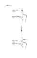
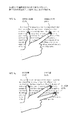
図2は、タッチパネルを用いた指による位置入力の例を示す図である。同図に示すように、指の接触した2点A、Bのそれぞれの始点から終点までの軌跡により、2点の関係を取得して入力を理解する。
FIG. 2 is a diagram illustrating an example of position input by a finger using a touch panel. As shown in the figure, the relationship between the two points is acquired and the input is understood from the trajectory from the start point to the end point of each of the two points A and B in contact with the finger.
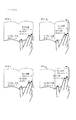
例1(平行方向)のように、各点の距離が変化せず、軌跡が平行になる場合がある。このような入力の例としては、対象物の平行移動などが考えられる。 As in Example 1 (parallel direction), the distance between points does not change and the trajectory may be parallel. As an example of such input, a parallel movement of an object can be considered.
例2(内側方向)のように、各点の軌跡が他方の点に向っている場合がある。このような入力の例としては、対象物の縮小または最小化などが考えられる。 As in Example 2 (inward direction), the locus of each point may be directed to the other point. Examples of such input include reduction or minimization of an object.
逆に、例3(外側方向)のように、各点の軌跡が他方から離れていく場合がある。このような入力の例としては、対象物の拡大または最大化などが考えられる。 Conversely, as in Example 3 (outward direction), the locus of each point may move away from the other. As an example of such input, enlargement or maximization of an object can be considered.
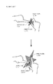
図3は、カメラなどの撮影装置を用いた指による位置入力の例を示す図である。ここでは、上述したタッチパネルに直接触れて指示を与える代わりに、カメラ301の有効領域302内で303及び304に示すように指先を動かすことにより、撮像した指示先(指先)位置を認識することで、指示位置を検知している。
FIG. 3 is a diagram illustrating an example of position input by a finger using a photographing apparatus such as a camera. Here, instead of directly touching the touch panel described above to give an instruction, the fingertip is moved in the
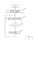
図4は、指示位置の軌跡を用いる処理の手順を示すフローチャートである。同図において、ステップS401で入力が検知されると、次のステップS402で終了が検知されない場合には、ステップS403に進み、軌跡検知処理が起動される。続いてステップS404において、検知した軌跡を入力情報として対応した処理が起動される。 FIG. 4 is a flowchart showing a processing procedure using the locus of the designated position. In the figure, when an input is detected in step S401, if the end is not detected in the next step S402, the process proceeds to step S403, and the locus detection process is activated. Subsequently, in step S404, processing corresponding to the detected locus as input information is started.
図5は、ステップS403の軌跡検知処理の手順を示すフローチャートである。ステップS501で指示位置検知処理が実行され、現在の指示位置の座標データが取得される。次にステップS502で組合せ特定処理が実行され、現在の各指示位置とそれぞれに最も近い直前の指示位置との組合せが特定される。続くステップS503で指示位置記憶処理が実行され、現在の指示位置を最適な指示位置データテーブル(最も近い直前の位置と同じテーブル)に格納する。 FIG. 5 is a flowchart showing the procedure of the locus detection process in step S403. In step S501, the designated position detection process is executed, and the coordinate data of the current designated position is acquired. Next, a combination specifying process is executed in step S502, and a combination of each current indicated position and the immediately preceding indicated position closest to each is specified. In the subsequent step S503, the designated position storage process is executed, and the current designated position is stored in the optimum designated position data table (the same table as the nearest previous position).
図6は、ステップS502の組合せ特定処理の手順を示すフローチャートである。同図において、ステップS601で、現在の指示位置の1つと直前の指示位置のそれぞれとの距離を求める処理が起動され、次のステップS602で、現在の指示位置と最も距離の短い直前の指示位置との組合せを特定する。続くステップS603で、該当する組合せがあった場合にはステップS604に進み、組となる直前の指示位置と同じテーブルに、現在の指示位置を追加する。これをステップS603において該当する組合せが無くなるまで繰り返す。 FIG. 6 is a flowchart showing the procedure of the combination specifying process in step S502. In the figure, in step S601, a process for obtaining the distance between one of the current designated positions and the previous designated position is started. In the next step S602, the designated position immediately before the current designated position and the shortest distance. Specify the combination. In subsequent step S603, if there is a corresponding combination, the process proceeds to step S604, and the current designated position is added to the same table as the designated position immediately before the combination. This is repeated until there is no corresponding combination in step S603.
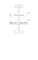
図7は、軌跡検知処理により記憶された指示位置データの例を示す図である。同図において、グラフ701のように時刻t1における点At1のXY座標は(3,3)であり、時刻t5における点At5のXY座標は(7,5)であり、この間t1からt5に対応する点A、Bの座標データがそれぞれテーブル702、703に格納されている。
FIG. 7 is a diagram illustrating an example of designated position data stored by the locus detection process. In the figure, the XY coordinate of the point At1 at time t1 is (3, 3) as shown in the
図8は、軌跡検知処理により取得される現在の指示位置データの例を示す図である。同図において、グラフ801のように、現在の時刻t6において、複数箇所の指示位置として、XY座標(8,6)である点aと、XY座標(8,8)である点bが存在し、取得された現在(t6)の位置データがテーブル802に格納されている。
FIG. 8 is a diagram illustrating an example of the current designated position data acquired by the locus detection process. In the same figure, at the current time t6, there are a point a having XY coordinates (8, 6) and a point b having XY coordinates (8, 8) at the current time t6 as shown in the
図9は、複数指示位置の軌跡検知処理で利用されるデータの流れを示す図である。同図において、テーブル901に、現在の指示位置データとして点a(8,6)及び点b(8,8)が取得されており、この現在の指示位置データを参照し、テーブル902に、現在の指示位置である各点に対して、直前の各指示位置との距離を取得する。この場合、例えば、点aに対して直前の指示位置At5との距離1.414、直前の指示位置Bt5との距離4.123が取得される。 FIG. 9 is a diagram illustrating a flow of data used in the locus detection process for a plurality of designated positions. In the figure, a point a (8, 6) and a point b (8, 8) are acquired as the current designated position data in the table 901. With reference to the current designated position data, the table 902 For each point that is the designated position, the distance to each previous designated position is acquired. In this case, for example, the distance 1.414 from the point a to the previous designated position At5 and the distance 4.123 from the previous designated position Bt5 are acquired.
その結果、点aは、最も距離の近い直前の指示位置At5と同じテーブル903に格納される。点bにも同様に、直前の指示位置Bt5と同じテーブル904に格納される。 As a result, the point a is stored in the same table 903 as the designated position At5 immediately before the closest distance. Similarly, the point b is stored in the same table 904 as the previous designated position Bt5.
図10は、指示面積の大きさを利用した軌跡検知処理の手順を示すフローチャートである。上述の例では、現在の各指示位置が、直前の複数の指示位置の中で距離の最も近い位置に対応するとして軌跡を求めたが、ここでは、現在の各指示位置が、直前の複数の指示位置の中で指示面積(例えば、タッチパネルにおける指の接触面積)が最も近位置に対応するとして軌跡を求める。 FIG. 10 is a flowchart illustrating a procedure of trajectory detection processing using the size of the designated area. In the above-described example, the trajectory is obtained by assuming that each current designated position corresponds to the closest position among a plurality of immediately preceding designated positions, but here, each current designated position is a plurality of immediately preceding designated positions. A trajectory is obtained assuming that the designated area (for example, the finger contact area on the touch panel) corresponds to the closest position among the designated positions.
同図において、ステップS1001で指示面積検知処理が起動され、現在の指示面積が取得される。次にステップS1002で組合せ特定処理が起動され、直前の指示面積との差分より現在の指示面積に最も近い直前の指示面積との組合せが特定される。続いてステップS1003で、指示面積記憶処理が起動され、現在の指示面積データが最適なテーブル(現在の指示面積に最も近い直前の指示面積が格納されたテーブル)に格納される。 In the figure, the designated area detection process is activated in step S1001, and the current designated area is acquired. In step S1002, a combination specifying process is started, and a combination with the immediately preceding designated area closest to the current designated area is identified based on the difference from the immediately preceding designated area. In step S1003, the designated area storage process is started, and the current designated area data is stored in the optimum table (the table in which the designated area immediately before the current designated area is stored).
図11は、ステップS1002における、指示面積の大きさを利用した組合せ特定処理の手順を示すフローチャートである。同図において、ステップS1101で、現在の指示位置の面積と直前の各指示位置の面積との差分を求める処理が起動され、次のステップS1102で、現在の指示位置と最も面積の近い直前の指示位置との組合せを特定する。続くステップS1103で該当する組合せがあった場合にはステップS1104に進み、最も面積の近い直前の指示位置と指示面積とのテーブルに、現在の指示位置と指示面積とを追加する。これをステップS1103において該当する組合せが無くなるまで繰り返す。 FIG. 11 is a flowchart showing the procedure of the combination specifying process using the size of the designated area in step S1002. In the figure, in step S1101, a process for obtaining the difference between the area of the current designated position and the area of each previous designated position is activated, and in the next step S1102, the previous instruction closest to the current designated position. Specify the combination with the position. If there is a corresponding combination in the subsequent step S1103, the process advances to step S1104 to add the current designated position and designated area to the table of the designated position and designated area immediately before the closest area. This is repeated until there is no corresponding combination in step S1103.
図12は、取得される現在の指示位置の面積の例を示す図である。グラフ1201において、現在の指示位置が点a(8,6)にあり、点aを指示した時のタッチパネルの接触の様子を示したのが拡大図1202である。その結果、指示位置の面積が求められる。
FIG. 12 is a diagram illustrating an example of the area of the current designated position acquired. In the
図13は、記憶された指示位置の面積データの例を示す図である。同図において、グラフ1301のように、時刻t1における指示位置点At1のXY座標は(3,3)、指示位置点Bt1のXY座標は(12,14)であり、時刻t5における指示位置点At5のXY座標は(7,5)、指示位置点Bt5のXY座標は(8,8)である。更に、現在の時刻t6において、現在の指示面積として点a(8,6)を含む指示面積1と、点b(8,8)を含む指示面積2とが存在する。
FIG. 13 is a diagram illustrating an example of the area data of the indicated position that is stored. In the figure, as indicated by a
また、テーブル1302において、時刻t1における点Aの面積は12.5であり、続いて時刻t2からt5に対応する点Aの面積データが格納されている。同様に、テーブル1303に、点Bの各時刻の面積データが格納されている。更に、テーブル1304に、取得された現在時刻t6の指示面積データとして点aを含む面積データ11.5、及び点bを含む面積データ20.0が格納されている。 In the table 1302, the area of the point A at the time t1 is 12.5, and subsequently, the area data of the point A corresponding to the time t2 to t5 is stored. Similarly, the area data of point B at each time is stored in the table 1303. Further, the area data 11.5 including the point a and the area data 20.0 including the point b are stored in the table 1304 as the acquired instruction area data at the current time t6.
図14は、指示面積の大きさを利用した軌跡取得処理で利用されるデータの流れを示す図である。同図において、テーブル1401に、現在の指示面積データとして、点a(8,6)を含む面積11.5と、点b(8,8)を含む面積20.0とが取得されており、現在の指示位置の面積データを参照し、テーブル1402に、各面積データと直前の各指示位置の面積データとの差分を取得する。ここでは、点aを含む指示面積11.5に対して、直前の指示面積Aとの差分0.5、及び直前の指示面積Bとの差分9.0が取得される。 FIG. 14 is a diagram illustrating a flow of data used in the trajectory acquisition process using the size of the designated area. In the same figure, an area 11.5 including the point a (8, 6) and an area 20.0 including the point b (8, 8) are acquired in the table 1401 as the current designated area data. With reference to the area data of the current designated position, a difference between each area data and the area data of each immediately preceding designated position is acquired in the table 1402. Here, with respect to the designated area 11.5 including the point a, a difference 0.5 from the previous designated area A and a difference 9.0 from the previous designated area B are acquired.
その結果、点aを含む指示面積データ11.5は、最も差分の小さい直前の指示面積Aと同じテーブル1403に格納される。また、点bを含む指示面積データも同様にして、直前の指示面積Bと同じテーブル1404に格納される。 As a result, the designated area data 11.5 including the point a is stored in the same table 1403 as the designated area A immediately before the smallest difference. Similarly, the designated area data including the point b is also stored in the same table 1404 as the designated area B immediately before.
〔実施形態2〕
本実施形態では、取得された2個所以上の指示位置の移動軌跡の組み合わせから、行うべき操作を解釈する処理について具体的に説明する。
[Embodiment 2]
In the present embodiment, a process for interpreting an operation to be performed based on a combination of movement trajectories of two or more designated positions acquired will be specifically described.
図15は、複数指示位置の軌跡を用いた操作手順を示すフローチャートである。同図において、ステップS1501で入力が検知されると、次のステップS1502で終了が検知されない場合には、ステップS1503に進み、移動軌跡検知処理が起動される。次に、ステップS1504で指示解釈処理が起動され、続いてステップS1505において指示に対応した処理が起動される。 FIG. 15 is a flowchart showing an operation procedure using a trajectory of a plurality of designated positions. In the figure, when an input is detected in step S1501, if the end is not detected in the next step S1502, the process proceeds to step S1503, and the movement locus detection process is activated. Next, in step S1504, instruction interpretation processing is activated, and in step S1505, processing corresponding to the instruction is activated.
図16は、ステップS1504における指示解釈処理の手順を示すフローチャートである。同図において、ステップS1601で指示位置間距離測定処理が起動され、現在の指示位置間の距離が測定される。次に、ステップS1602に進み、指示位置間の距離変化の取得処理が起動され、指示位置間の距離の変化を取得する。続いてステップS1603で、距離変化に基づく指示解釈処理が起動され、取得された距離変化に応じて行なうべき操作を解釈する。 FIG. 16 is a flowchart showing the procedure of instruction interpretation processing in step S1504. In the figure, the distance measurement process between designated positions is started in step S1601, and the distance between the current designated positions is measured. Next, proceeding to step S1602, a process for acquiring a change in distance between designated positions is started, and a change in the distance between designated positions is obtained. In step S1603, an instruction interpretation process based on the distance change is activated to interpret an operation to be performed according to the acquired distance change.
図17は、ステップS1602における指示位置間の距離変化の取得処理の手順を示すフローチャートである。同図において、ステップS1701で移動開始時の指示位置間の距離が測定され、続いてステップS1702で移動終了時の指示位置間の距離が測定される。次にステップS1703に進み、移動開始時の指示位置間の距離と、移動終了時の指示位置間の距離との差分が取得される。 FIG. 17 is a flowchart illustrating a procedure for acquiring a change in distance between designated positions in step S1602. In the figure, the distance between the designated positions at the start of movement is measured in step S1701, and then the distance between the designated positions at the end of movement is measured in step S1702. In step S1703, the difference between the distance between the designated positions at the start of movement and the distance between the designated positions at the end of movement is acquired.
図18は、ステップS1603における距離変化に基づく指示解釈処理の手順を示すフローチャートである。同図において、ステップS1801において、変化量が0より小さかった場合には縮小操作と解釈される(ステップS1802)。同様に変化量が0より大きかった場合には、拡大操作と解釈され(ステップS1803)、変化量が0に等しい場合には、縮小または拡大操作以外であると解釈される(ステップS1804)。 FIG. 18 is a flowchart showing the procedure of the instruction interpretation process based on the distance change in step S1603. In the figure, if the change amount is smaller than 0 in step S1801, it is interpreted as a reduction operation (step S1802). Similarly, when the change amount is larger than 0, it is interpreted as an enlargement operation (step S1803), and when the change amount is equal to 0, it is interpreted as other than the reduction or enlargement operation (step S1804).
図19は、距離変化に基づく指示解釈処理の別の手順を示すフローチャートである。同図において、ステップS1901において、指示位置間の距離変化の取得処理により取得された距離変化より操作倍率が取得される。次に、s1902において変化率が取得され、続いてステップS1903で操作倍率と変化率データより実倍率が取得される。 FIG. 19 is a flowchart showing another procedure of the instruction interpretation process based on the distance change. In the figure, in step S1901, the operation magnification is acquired from the distance change acquired by the distance change acquisition process between the designated positions. Next, the change rate is acquired in s1902, and then the actual magnification is acquired from the operation magnification and the change rate data in step S1903.
計算式:実倍率=100−(100−操作倍率X)×変化率α
図20は、縮小操作として解釈される操作例を示す図である。同図において、移動開始時t1における指示位置点A及び点Bから、移動終了時t5における指示位置点A’及び点B’へと変化した場合、縮小操作であると解釈される。
Calculation formula: actual magnification = 100− (100−operation magnification X) × change rate α
FIG. 20 is a diagram illustrating an operation example that is interpreted as a reduction operation. In the figure, when the designated position point A and point B at the movement start time t1 are changed to the designated position point A ′ and point B ′ at the movement end time t5, it is interpreted as a reduction operation.
図21は、縮小操作として解釈されるデータの例を示す図である。同図において、グラフ2101の各指示位置のXY座標は、移動開始時t1では点At1(3,3), 点Bt1(12,10)、移動終了時t5では点At5(7,5)、点Bt5(8,6)である。この時、テーブル2102に示すように、指示位置A,B間の距離は移動開始時t1では15.000、移動終了時t6では1.118であり、移動開始時t1から移動終了時t5の間の指示位置間の距離の変化量は−13.882である。また、移動開始時t1から移動終了時t5の間の指示位置間の距離変化の倍率は7%である。
FIG. 21 is a diagram illustrating an example of data interpreted as a reduction operation. In the figure, the XY coordinates of each indicated position on the
図22は、拡大操作として解釈される操作例を示す図である。同図において、移動開始時t1の指示位置点A及び点Bから、移動終了時t5の指示位置点A’及び点B’へと変化した場合、拡大操作であると解釈される。 FIG. 22 is a diagram illustrating an operation example that is interpreted as an enlargement operation. In the figure, when the designated position points A and B at the start of movement t1 change to designated position points A 'and B' at the end of movement t5, it is interpreted as an enlargement operation.
図23は、拡大操作として解釈されるデータの例を示す図である。同図において、グラフ2301のように各指示位置のXY座標は、移動開始時t1では点At1(7,5)、点Bt1(8,6)、移動終了時t5では点At5(3,3)、点Bt5(12,10)である。この時、テーブル2302に示すように、指示位置A,B間の距離は移動開始時t1では1.118、移動終了時t6では11.402であり、移動開始時t1から移動終了時t5の間の指示位置間の距離の変化量は+13.586である。また、移動開始時t1から移動終了時t5の間の指示位置間の距離変化の倍率は1020%である。
FIG. 23 is a diagram illustrating an example of data interpreted as an enlargement operation. In the same figure, as indicated by a
〔実施形態3〕
本実施形態では、取得された2個所以上の指示位置の移動軌跡の組み合わせから、行うべき操作を解釈する際に、2つの指示位置を結ぶ線と基準線とのなす角の角度(以下、単に指示位置の角度と称する)の変化に着目した例について具体的に説明する。
[Embodiment 3]
In the present embodiment, when an operation to be performed is interpreted from a combination of acquired movement loci of two or more designated positions, an angle between a line connecting the two designated positions and a reference line (hereinafter, simply referred to as “the operation path to be performed”). An example focusing on the change in the designated position angle will be described in detail.
図24は、指示位置の角度変化を利用する指示解釈処理の流れを示す図である。同図において、ステップS2401で指示位置の角度の測定処理が起動され、各時点において、指示位置の角度が測定される。次に、ステップS2402に進み、指示位置角度変化取得処理が起動され、指示位置を結ぶ線の角度の変化を取得する。続いて、ステップS2403で角度変化に基づく指示解釈処理が起動され、取得された角度変化に応じて行なうべき操作を解釈する。 FIG. 24 is a diagram illustrating a flow of instruction interpretation processing using an angle change of the designated position. In the figure, in step S2401, the process of measuring the angle of the designated position is started, and the angle of the designated position is measured at each time point. Next, proceeding to step S2402, the designated position angle change acquisition process is activated to obtain a change in the angle of the line connecting the designated positions. Subsequently, in step S2403, an instruction interpretation process based on the angle change is activated to interpret an operation to be performed according to the acquired angle change.
図25は、指示位置の角度変化の測定処理の手順を示すフローチャートである。同図において、ステップS2501で移動開始時の指示位置を結ぶ線の角度が測定され、続いてステップS2502で移動終了時の指示位置を結ぶ線の角度が測定される。次に、ステップS2503に進み、移動開始時の指示位置を結ぶ線の角度と、移動終了時の指示位置を結ぶ線の角度との差分が取得される。 FIG. 25 is a flowchart illustrating the procedure of the measurement process of the change in the angle of the designated position. In the figure, the angle of the line connecting the designated positions at the start of movement is measured in step S2501, and then the angle of the line connecting the designated positions at the end of movement is measured in step S2502. In step S2503, the difference between the angle of the line connecting the designated positions at the start of movement and the angle of the line connecting the designated positions at the end of movement is acquired.
図26は、角度変化に基づく指示解釈処理の手順を示すフローチャートである。同図において、ステップS2601で、変化量が0°より大きかった場合には、左回転操作として解釈される(ステップS2602)。同様に変化量が0°より小さかった場合には右回転操作として解釈され(ステップS2603)、変化量が0°に等しい場合には回転操作以外であると解釈される(ステップS2604)。 FIG. 26 is a flowchart illustrating a procedure of instruction interpretation processing based on an angle change. In the figure, if the amount of change is greater than 0 ° in step S2601, it is interpreted as a left rotation operation (step S2602). Similarly, when the change amount is smaller than 0 °, it is interpreted as a right rotation operation (step S2603), and when the change amount is equal to 0 °, it is interpreted as other than the rotation operation (step S2604).
図27は、右回転操作として解釈される操作例を示す図である。同図において、移動開始時t1の指示位置点A及び点Bから、移動終了時t5の指示位置点A’及び点B’へと変化した場合、右回転操作であると解釈される。 FIG. 27 is a diagram illustrating an operation example that is interpreted as a clockwise rotation operation. In the figure, when the designated position point A and point B at the start of movement t1 change to the designated position point A 'and point B' at the end of movement t5, it is interpreted as a clockwise rotation operation.
図28は、指示位置を結ぶ線の角度及びその変化データのうち、右回転操作として解釈されるデータ例を示す図である。同図において、グラフ2801のように指示位置AB間の角度は、移動開始時t1では、X軸に対して60度であり、移動終了時t5では26度である。この時、テーブル2802のように、移動開始時t1から移動終了時t5の間の指示位置間の角度の変化量は−34°である。 FIG. 28 is a diagram illustrating a data example that is interpreted as a right rotation operation among the angle of the line connecting the designated positions and the change data thereof. In the drawing, as shown in the graph 2801, the angle between the designated positions AB is 60 degrees with respect to the X axis at the movement start time t1 and 26 degrees at the movement end time t5. At this time, as shown in the table 2802, the change amount of the angle between the designated positions from the movement start time t1 to the movement end time t5 is −34 °.
図29は、左回転操作として解釈される操作例を示す図である。移動開始時t1の指示位置点A及び点Bから、移動終了時t5の指示位置点A’及び点B’へと変化した場合、左回転操作であると解釈される。 FIG. 29 is a diagram illustrating an operation example interpreted as a left rotation operation. When the designated position point A and point B at the start of movement t1 change to the designated position point A 'and point B' at the end of movement t5, it is interpreted as a left rotation operation.
図30は、指示位置を結ぶ線の角度及びその変化を示すデータのうち、左回転操作として解釈されるデータの例を示す図である。同図において、グラフ3001のように指示位置AB間の角度は、移動開始時t1では、X軸に対して60度であり、移動終了時t5では87度である。この時、テーブル3002のように、移動開始時t1から移動終了時t5の間の指示位置間の角度の変化量は+27°である。
FIG. 30 is a diagram illustrating an example of data interpreted as a left rotation operation among the data indicating the angle of the line connecting the designated positions and the change thereof. In the drawing, as shown in the
〔実施形態4〕
本実施形態では、取得された2個所以上の指示位置の移動軌跡の組み合わせから行うべき操作を解釈する際に、固定指示位置と移動指示位置との関係の変化に着目した例について具体的に説明する。
[Embodiment 4]
In the present embodiment, an example in which attention is paid to a change in the relationship between the fixed instruction position and the movement instruction position when interpreting an operation to be performed from a combination of movement trajectories of two or more acquired instruction positions will be specifically described. To do.
図31は、固定指示位置と移動指示位置の関係を利用する指示解釈処理の手順を示すフローチャートである。同図において、ステップS3101で固定指示位置検出処理が起動され、固定指示位置が検出される。次に、ステップS3102に進み、固定指示位置に基づく指示解釈処理が起動され、行なうべき操作を解釈する。 FIG. 31 is a flowchart illustrating a procedure of instruction interpretation processing using the relationship between the fixed instruction position and the movement instruction position. In the figure, a fixed designated position detection process is activated in step S3101 to detect a fixed designated position. Next, proceeding to step S3102, an instruction interpretation process based on the fixed instruction position is activated, and an operation to be performed is interpreted.
図32は、ステップS3101における固定指示位置検出処理の手順を示すフローチャートである。同図において、固定指示位置検出処理が起動されると、ステップS3201で時刻tの指示位置が検出され、続くステップS3202で位置データが存在する場合には、次のステップS3203に進み、指示位置の初期値と比較する。その結果、位置データが一致しなかった場合には、ステップS3204で指示位置は移動していると判断される。位置データが一致した場合にはステップS3205に進み、時刻tを進めて、再びステップS3201から繰り返す。そして、ステップS3202において位置データが存在しない場合にはステップS3206で指示位置は固定と判断され、固定指示位置が検出される。 FIG. 32 is a flowchart showing the procedure of the fixed instruction position detection process in step S3101. In the figure, when the fixed designated position detection process is activated, the designated position at time t is detected in step S3201, and if position data exists in the subsequent step S3202, the process proceeds to the next step S3203, where the designated position is detected. Compare with the initial value. As a result, if the position data do not match, it is determined in step S3204 that the indicated position has moved. If the position data match, the process proceeds to step S3205, advances the time t, and repeats from step S3201. If no position data exists in step S3202, the designated position is determined to be fixed in step S3206, and the fixed designated position is detected.
図33は、移動方向に基づく指示解釈処理の手順を示すフローチャートである。同図において、ステップS3301で指示位置移動方向判定処理が起動され、移動指示位置の移動方向が判定される。次にステップS3302で、判定された移動方向に基づき指示操作を解釈する。 FIG. 33 is a flowchart illustrating a procedure of instruction interpretation processing based on the moving direction. In the figure, in step S3301, designated position movement direction determination processing is activated, and the movement direction of the movement designated position is determined. In step S3302, the instruction operation is interpreted based on the determined moving direction.
移動方向が上であった場合には、ステップ3303に進み、次項目操作として解釈する。また、この他に次ページ操作、または次画面操作、または末尾行操作、または上画面移動操作、または上下方向のみの拡大操作、または上下方向のみの縮小操作、として解釈される場合もある。移動方向が下であった場合には、ステップ3304に進み、前項目操作として解釈する。また、この他に前ページ操作、または前画面操作、または先頭行操作、または下画面移動操作、または上下方向のみの拡大操作、または上下方向のみの縮小操作、として解釈される場合もある。 If the moving direction is up, the process proceeds to step 3303 and is interpreted as the next item operation. In addition to this, there are cases where it is interpreted as a next page operation, a next screen operation, a last line operation, an upper screen moving operation, an enlargement operation only in the vertical direction, or a reduction operation only in the vertical direction. If the movement direction is down, the process proceeds to step 3304 and is interpreted as a previous item operation. In addition to this, there are cases where it is interpreted as a previous page operation, a previous screen operation, a first line operation, a lower screen moving operation, an enlargement operation only in the vertical direction, or a reduction operation only in the vertical direction.
移動方向が左であった場合には、ステップ3305に進み、次項目操作として解釈する。また、この他に次ページ操作、または次画面操作、または末尾行操作、または左画面移動操作、または左右方向のみの拡大操作、または左右方向のみの縮小操作、として解釈される場合もある。移動方向が右であった場合には、ステップ3306に進み、前項目操作として解釈する。また、この他に前ページ操作、または前画面操作、または先頭行操作、または右画面移動操作、または左右方向のみの拡大操作、または左右方向のみの縮小操作、として解釈される場合もある。 If the moving direction is left, the process proceeds to step 3305 and is interpreted as a next item operation. In addition to this, there are cases where it is interpreted as the next page operation, the next screen operation, the last line operation, the left screen movement operation, the enlargement operation only in the left-right direction, or the reduction operation only in the left-right direction. If the moving direction is right, the process proceeds to step 3306 and is interpreted as a previous item operation. In addition to this, there are cases where it is interpreted as a previous page operation, a previous screen operation, a first line operation, a right screen movement operation, an enlargement operation only in the left-right direction, or a reduction operation only in the left-right direction.
図34は、ステップS3301の指示位置移動方向判定処理の手順を示すフローチャートである。同図において、ステップS3401で指示位置の移動量が取得され、次のステップS3402で、移動指示位置の現在座標より移動方向が判定される。その際、移動指示位置の現在座標(X,Y)のarctangentを求め、単位をラジアンから度数に変換する。 FIG. 34 is a flowchart illustrating the procedure of the designated position movement direction determination process in step S3301. In the figure, the movement amount of the designated position is acquired in step S3401, and in the next step S3402, the movement direction is determined from the current coordinates of the movement designated position. At this time, arctangent of the current coordinates (X, Y) of the movement instruction position is obtained, and the unit is converted from radians to degrees.
図35は、指示位置移動方向判定処理で利用される角度の解釈について表す図である。同図において、3501のように、X軸を基準に360°をY軸正方向 0°〜180、Y軸負方向−1°〜−179°に分けている。 FIG. 35 is a diagram illustrating the interpretation of the angles used in the designated position movement direction determination process. In the figure, as indicated by 3501, 360 ° is divided into a Y-axis positive direction of 0 ° to 180 ° and a Y-axis negative direction of −1 ° to −179 ° with reference to the X axis.
これに従い、0°を中心として±35°(−35°〜35°)を右方向として解釈し、90°を中心として±35°(65°〜135°)を上方向として解釈し、180°を中心として±35°(155°〜180°及び−179°〜−145°)を左方向として解釈し、−90°を中心として±35°(−65°〜−135°)を下方向として解釈する。また、それぞれ45°,135°,−135°,−45°を中心とした±10°の範囲については、それ以外の操作であると解釈する。 Accordingly, ± 35 ° (−35 ° to 35 °) is interpreted as the right direction around 0 °, ± 35 ° (65 ° to 135 °) is interpreted as the upward direction around 90 °, and 180 ° ± 35 ° (155 ° to 180 ° and -179 ° to -145 °) as the left direction, and ± 35 ° (-65 ° to -135 °) as the downward direction from -90 ° Interpret. In addition, the range of ± 10 ° centered at 45 °, 135 °, −135 °, and −45 ° is interpreted as other operations.
図36は、左移動操作として解釈される操作例を示す図である。同図において、固定指示位置点Aが固定されており、移動指示位置点BがBt1から点Bt5へと移動した場合、左移動操作であると解釈される。 FIG. 36 is a diagram illustrating an operation example interpreted as a left movement operation. In the figure, when the fixed instruction position point A is fixed and the movement instruction position point B moves from Bt1 to point Bt5, it is interpreted as a left movement operation.
図37は、左移動操作として解釈されるデータの例を示す図である。同図において、グラフ3701のように固定指示位置の座標は点A(3,3)であり、移動指示位置の座標は移動開始時t1では点Bt1(6,3)、移動終了時t5では点Bt5(4,2)である。テーブル3702は、t1からt5における、固定指示位置点A及び、移動指示位置点Bの位置データを示すものである。3703は、指示位置移動データを示すものであり、移動終了時t5の指示位置の移動量は固定指示位置点Aが0、移動指示位置点Bが2.236であり、また移動方向は−153.43°である。
FIG. 37 is a diagram illustrating an example of data interpreted as a left movement operation. In the figure, the coordinate of the fixed instruction position is a point A (3, 3) as shown in the
図38は、上移動操作として解釈される操作例を示す図である。同図において、固定指示位置点Aが固定されており、移動指示位置点BがBt1から点Bt5へと移動した場合、上移動操作であると解釈される。 FIG. 38 is a diagram illustrating an operation example that is interpreted as an upward movement operation. In the figure, when the fixed instruction position point A is fixed and the movement instruction position point B moves from Bt1 to point Bt5, it is interpreted as an upward movement operation.
図39は、上移動操作として解釈される場合のデータの例を示す図である。同図において、グラフ3901のように固定指示位置の座標は点A(6,6)であり、移動指示位置の座標は移動開始時t1では点Bt1(5,1)、移動終了時t5では点Bt5(7,4)である。テーブル3902は、t1からt5における、固定指示位置点A及び、移動指示位置点Bの位置データを示すものである。テーブル3903は、指示位置移動データを示すものであり、移動終了時t5の指示位置の移動量は固定指示位置点Aが0、移動指示位置点Bが3.606であり、また移動方向は56.31°である。
FIG. 39 is a diagram illustrating an example of data when interpreted as an upward movement operation. In the figure, the coordinate of the fixed instruction position is a point A (6, 6) as in the
図40は、下移動操作として解釈される操作例を示す図である。同図において、固定指示位置点Aが固定されており、移動指示位置点BがBt1から点Bt5へと移動した場合、下移動操作であると解釈される。 FIG. 40 is a diagram illustrating an operation example that is interpreted as a downward movement operation. In the figure, when the fixed instruction position point A is fixed and the movement instruction position point B moves from Bt1 to point Bt5, it is interpreted as a downward movement operation.
図41は、下移動操作として解釈されるデータの例を示す図である。同図において、グラフ4101のように固定指示位置の座標は点A(3,3)であり、移動指示位置の座標は移動開始時t1では点Bt1(5,8)、移動終了時t5では点Bt5(5,5)である。テーブル4102は、t1からt5における、固定指示位置点A及び、移動指示位置点Bの位置データを示すものである。テーブル4103は、指示位置移動データを示すものであり、移動終了時t5の時点での指示位置の移動量は固定指示位置点Aが0、移動指示位置点Bが3.000であり、また移動方向は−90°である。
FIG. 41 is a diagram illustrating an example of data interpreted as a downward movement operation. In the same figure, the coordinate of the fixed instruction position is the point A (3, 3) as in the
図42は、右移動操作として解釈される操作例を示す図である。同図において、固定指示位置Aが固定されており、移動指示位置点Bが4201のようにBt1から4202のように点Bt5へと移動した場合、右移動操作であると解釈される。 FIG. 42 is a diagram illustrating an operation example that is interpreted as a right movement operation. In the same figure, when the fixed instruction position A is fixed and the movement instruction position point B moves from Bt1 to Bt5 like 4201, it is interpreted as a right movement operation.
図43は、右移動操作として解釈されるデータの例を示す図である。同図において、グラフ4301のように固定指示位置の座標は点A(6,6)であり、移動指示位置の座標は移動開始時t1では点Bt1(2,6)、移動終了時t5では点Bt5(5,5)である。テーブル4302は、t1からt5における、固定指示位置点A及び、移動指示位置点Bの位置データを示すものである。テーブル4303は、指示位置移動データを示すものであり、移動終了時t5の指示位置の移動量は固定指示位置点Aが0、移動指示位置点Bが3.162であり、また移動方向は−18.43°である。
FIG. 43 is a diagram illustrating an example of data interpreted as a right movement operation. In the figure, the coordinate of the fixed instruction position is a point A (6, 6) as shown in the
〔実施形態5〕
本実施形態では、取得された2個所以上の指示位置の移動軌跡の組み合わせから行うべき操作を解釈する際に、固定指示位置と移動指示位置との距離変化に着目した例について具体的に説明する。
[Embodiment 5]
In this embodiment, an example in which attention is paid to a change in distance between a fixed instruction position and a movement instruction position when an operation to be performed from a combination of movement trajectories of two or more acquired instruction positions is interpreted will be specifically described. .
図44は、固定指示位置と移動指示位置との距離変化を利用する指示解釈処理の手順を示すフローチャートである。同図において、指示解釈処理が起動されると、ステップS4401で指示位置間距離測定処理が起動され、固定指示位置と移動指示位置との各時点の距離が測定される。次にステップS4402に進み、指示位置間距離変化取得処理によって、指示位置間の距離変化が取得される。続くステップS4403で、指示位置距離変化に基づく指示解釈処理が起動され、取得された指示位置間の距離変化に対応して、行なうべき操作を解釈する。 FIG. 44 is a flowchart showing a procedure of instruction interpretation processing using a change in distance between the fixed instruction position and the movement instruction position. In the figure, when the instruction interpretation process is activated, the distance measurement process between designated positions is activated in step S4401, and the distance at each time point between the fixed designated position and the movement designated position is measured. Next, proceeding to step S4402, the distance change between the designated positions is obtained by the distance change obtaining process between designated positions. In subsequent step S4403, an instruction interpretation process based on the indicated position distance change is activated, and an operation to be performed is interpreted in response to the acquired change in distance between indicated positions.
図45は、ステップS4403の指示位置間距離変化に基づく指示解釈処理の手順を示すフローチャートである。同図において、ステップS4501で変化量が判断され、変化量が減少傾向にある場合には縮小操作として解釈し(ステップS4502)、変化量が増加傾向にある場合には拡大操作として解釈する(ステップS4503)。 FIG. 45 is a flowchart showing a procedure of instruction interpretation processing based on a change in distance between designated positions in step S4403. In the figure, the amount of change is determined in step S4501, and when the amount of change is decreasing, it is interpreted as a reduction operation (step S4502), and when the amount of change is increasing, it is interpreted as an enlargement operation (step S4502). S4503).
図46は、縮小操作として解釈される操作例を示す図である。同図において、固定指示位置(点A)が固定されており、移動指示位置(点B)が、点Bt1から固定指示位置(点A)の方向にある点Bt5へと移動した場合、縮小操作であると解釈される。 FIG. 46 is a diagram illustrating an operation example that is interpreted as a reduction operation. In the figure, when the fixed instruction position (point A) is fixed and the movement instruction position (point B) moves from the point Bt1 to the point Bt5 in the direction of the fixed instruction position (point A), the reduction operation is performed. It is interpreted as
図47は、縮小操作として解釈される場合のデータの例を示す図である。同図において、グラフ4701のように固定指示位置の座標は点A(3,3)であり、移動指示位置の座標は移動開始時t1では点Bt1(6,3)、移動終了時t5では点Bt5(4,2)である。テーブル4702は、時刻t1からt5における、固定指示位置点A及び、移動指示位置点Bの位置データを示すものである。テーブル4703は、指示位置間の距離変化データを示すものであり、移動開始時t1の指示位置AB間の距離は3.000であり、移動終了時t5の指示位置AB間の距離は1.414であり、指示位置AB間の距離のt1からt5に対する倍率は47%である。
FIG. 47 is a diagram illustrating an example of data when interpreted as a reduction operation. In the same figure, the coordinate of the fixed instruction position is a point A (3, 3) as shown in the
図48は、拡大操作として解釈される操作例を示す図である。同図において、固定指示位置点Aが固定されており、移動指示位置点BがBt1から固定指示位置点Aとは反対の方向にある点Bt5へと移動した場合、拡大操作であると解釈される。 FIG. 48 is a diagram illustrating an operation example that is interpreted as an enlargement operation. In the figure, when the fixed instruction position point A is fixed and the movement instruction position point B moves from Bt1 to a point Bt5 in the opposite direction to the fixed instruction position point A, it is interpreted as an enlargement operation. The
図49は、縮小操作として解釈される場合のデータの例を示す図である。同図において、グラフ4901のように固定指示位置の座標は点A(3,3)であり、移動指示位置の座標は移動開始時t1では点Bt1(4,2)、移動終了時t5では点Bt5(6,3)である。テーブル4902は、t1からt5における、固定指示位置点A及び、移動指示位置点Bの位置データを示すものである。テーブル4903は、固定指示位置間の距離変化データを示すものであり、移動開始時t1の指示位置AB間の距離は1.414であり、移動終了時t5の指示位置AB間の距離は3.000であり、指示位置AB間の距離のt1からt5に対する倍率は212%である。
FIG. 49 is a diagram illustrating an example of data when interpreted as a reduction operation. In the same figure, the coordinate of the fixed instruction position is a point A (3, 3) as shown in the
図50は、固定指示位置を中心とした縮小操作として解釈される操作例を示す図である。同図において、固定指示位置点Aが固定されており、5001のように移動指示位置1点Bt1及び移動指示位置2点Ct1があり、5002のように固定指示位置点Aの方向に向かって、移動指示位置1点Bt1がBt5へ、移動指示位置2点Ct1が点Ct5へと移動した場合、それぞれ固定指示位置点A方向への縮小操作であると解釈される。
FIG. 50 is a diagram illustrating an operation example that is interpreted as a reduction operation centered on the fixed instruction position. In the drawing, the fixed instruction position point A is fixed, and there are a
図51は、固定指示位置を中心とした縮小操作として解釈される場合のデータの例を示す図である。同図において、グラフ5101のように固定指示位置の座標は点A(3,3)であり、移動指示位置1である点Bの座標は移動開始時t1では点Bt1(4,8)、移動終了時t5では点Bt5(5,5)であり、移動指示位置2である点Cの座標は移動開始時t1では点Ct1(2,2)、移動終了時t5では点Ct5(4,3.5)である。テーブル5102は、t1からt5における、固定指示位置点A及び、移動指示位置1点B、移動指示位置2点Cの位置データを示すものである。
FIG. 51 is a diagram illustrating an example of data when interpreted as a reduction operation centered on the fixed instruction position. In the same figure, the coordinate of the fixed instruction position is a point A (3, 3) as in the
テーブル5103は、固定指示位置間の距離変化データを示すものであり、指示位置間距離変化データ1において、移動開始時t1の指示位置AB間の距離は5.099であり、移動終了時t5の指示位置AB間の距離は2.828であり、指示位置AB間の距離のt1からt5に対する倍率は55%である。また、指示位置間距離変化データ2において、移動開始時t1の指示位置AC間の距離は1.414であり、移動終了時t5の指示位置AC間の距離は1.118であり、指示位置AC間の距離のt1からt5に対する倍率は79%である。
The table 5103 shows distance change data between the fixed designated positions. In the designated position
〔実施形態6〕
本実施形態では、取得された2個所以上の指示位置の移動軌跡の組み合わせから行うべき操作を解釈する際に、固定指示位置の存在と、その他の移動指示位置間の距離変化に着目した例について具体的に説明する。
[Embodiment 6]
In the present embodiment, when interpreting an operation to be performed from a combination of movement trajectories of two or more designated positions acquired, an example focusing on the presence of a fixed designated position and a change in distance between other movement designated positions This will be specifically described.
図52は、移動指示位置間の距離を利用する処理の手順を示すフローチャートである。同図において、固定指示位置対応指示解釈処理が起動されると、ステップS5201で移動指示位置間距離測定処理が起動され、現在の移動指示位置間の距離が測定される。次に、ステップS5202に進み、移動指示位置間距離変化取得処理が起動され、取得された距離の変化量を取得する。続いて、ステップS5203で移動指示位置間の距離変化に基づく指示解釈処理が起動され、取得された移動指示位置間距離の変化量に基づいて行なうべき操作を解釈する。 FIG. 52 is a flowchart illustrating a procedure of processing using the distance between the movement instruction positions. In the figure, when the fixed instruction position corresponding instruction interpretation process is activated, the movement instruction position distance measurement process is activated in step S5201, and the distance between the current movement instruction positions is measured. Next, proceeding to step S5202, the movement instruction position distance change acquisition process is started, and the acquired distance change amount is acquired. Subsequently, in step S5203, an instruction interpretation process based on a change in the distance between the movement instruction positions is started, and an operation to be performed is interpreted based on the obtained change amount of the distance between the movement instruction positions.
図53は、移動指示位置間の距離変化に基づく指示解釈処理の手順を示すフローチャートである。同図において、ステップS5301で固定指示位置が存在する場合には、ステップS5302に進み、変化量が0より小さい場合には、ステップS5303で固定指示位置に対する縮小操作として解釈される。変化量が0より大きい場合には、ステップS5304で固定指示位置に対する拡大操作として解釈される。変化量が0に等しい場合には、ステップS5305で縮小または拡大操作以外であると解釈する。ステップS5301において、固定指示位置の存在が確認されない場合には、ステップS5306に進み、全体に対する操作であると解釈する。 FIG. 53 is a flowchart illustrating a procedure of instruction interpretation processing based on a change in distance between movement instruction positions. In the figure, if a fixed instruction position exists in step S5301, the process proceeds to step S5302, and if the change amount is smaller than 0, it is interpreted as a reduction operation for the fixed instruction position in step S5303. If the amount of change is greater than 0, it is interpreted as an enlargement operation for the fixed designated position in step S5304. If the amount of change is equal to 0, it is interpreted as other than a reduction or enlargement operation in step S5305. If the presence of the fixed instruction position is not confirmed in step S5301, the process proceeds to step S5306 and is interpreted as an operation for the whole.
図54は、固定指示位置を中心とした縮小操作として解釈される操作例を示す図である。同図において、固定指示位置点Aが固定されており、2つの移動指示位置点Bt1及び移動指示位置点Ct1があり、それらが固定指示位置点Aの方向に向かって、移動指示位置点Bt1がBt5へ、移動指示位置点Ct1が点Ct5へと移動した場合、移動指示位置間の距離の変化量に応じて、固定指示位置点Aを中心とした縮小操作であると解釈される。 FIG. 54 is a diagram illustrating an operation example that is interpreted as a reduction operation centered on the fixed instruction position. In the figure, the fixed instruction position point A is fixed, and there are two movement instruction position points Bt1 and a movement instruction position point Ct1, and these movement instruction position points Bt1 are in the direction of the fixed instruction position point A. When the movement instruction position point Ct1 moves to point Ct5 to Bt5, it is interpreted as a reduction operation centered on the fixed instruction position point A according to the amount of change in the distance between the movement instruction positions.
図55は、固定指示位置を中心とした縮小操作として解釈される場合のデータ例を示す図である。同図において、グラフ5501のように固定指示位置の座標は点A(3,3)であり、移動指示位置点Bの座標は移動開始時t1では点Bt1(4,8)、移動終了時t5では点Bt5(5,5)であり、移動指示位置点Cの座標は移動開始時t1では点Ct1(3,2)、移動終了時t5では点Ct5(4,2.8)である。
FIG. 55 is a diagram illustrating an example of data when interpreted as a reduction operation centered on the fixed instruction position. In the same figure, the coordinate of the fixed instruction position is point A (3, 3) as in the
テーブル5502は、t1からt5における固定指示位置点A及び、移動指示位置点B、移動指示位置点Cの位置データを示すものである。テーブル5503は、移動指示位置間の距離変化データを示すものであり、指示位置間距離変化データにおいて、移動開始時t1の指示位置BC間の距離は6.083であり、移動終了時t5の指示位置BC間の距離は2.417であり、指示位置BC間の距離のt1からt5に対する変化量は40%である。 A table 5502 shows position data of the fixed instruction position point A, the movement instruction position point B, and the movement instruction position point C from t1 to t5. The table 5503 shows the distance change data between the movement instruction positions. In the distance change data between the instruction positions, the distance between the instruction positions BC at the start of movement t1 is 6.083, and the instruction at the end of movement t5 is indicated. The distance between the positions BC is 2.417, and the amount of change in the distance between the designated positions BC from t1 to t5 is 40%.
図56は、固定指示位置を中心とした拡大操作として解釈される操作例を示す図である。同図において、固定指示位置点Aが固定されており、移動指示位置1点Bt1及び移動指示位置2点Ct1があり、それらが固定指示位置点Aの方向に向かって、移動指示位置1点Bt1がBt5へ、移動指示位置2点Ct1が点Ct5へと移動した場合、移動指示位置間の距離の比に応じて、固定指示位置点Aを中心とした拡大操作であると解釈される。
FIG. 56 is a diagram illustrating an operation example that is interpreted as an enlargement operation centered on the fixed instruction position. In the figure, the fixed instruction position point A is fixed, and there are a
図57は、固定指示位置を中心とした拡大操作として解釈される場合のデータ例を示す図である。同図において、グラフ5701のように固定指示位置の座標は点A(3,3)であり、移動指示位置1である点Bの座標は移動開始時t1では点Bt1(5,5)、移動終了時t5では点Bt5(4,8)であり、移動指示位置2である点Cの座標は移動開始時t1では点Ct1(4,2.8)、移動終了時t5では点Ct5(2,2)である。
FIG. 57 is a diagram illustrating an example of data when interpreted as an enlargement operation centered on the fixed instruction position. In the same figure, the coordinate of the fixed instruction position is point A (3, 3) as shown in the
テーブル5702は、t1からt5における固定指示位置点A及び、移動指示位置1点B、移動指示位置2点Cの位置データを示すものである。テーブル5703は、移動指示位置間の距離変化データを示すものであり、指示位置間距離変化データ1において、移動開始時t1の指示位置BC間の距離は2.417であり、移動終了時t5の指示位置BC間の距離は6.325であり、指示位置BC間の距離のt1からt5に対する変化量は262%である。
A table 5702 shows position data of the fixed instruction position point A, the
図58は、固定指示位置を中心とした複数移動指示操作として解釈される操作例を示す図である。同図において、固定指示位置点Aが固定されており、5801のように移動指示位置1点Bt1及び移動指示位置2点Ct1、移動指示位置3点Dt1、があり、5802のように固定指示位置点Aの方向に向かって、移動指示位置1点Bt1がBt5へ、移動指示位置2点Ct1が点Ct5へ、移動指示位置3点Dt1が点Dt5へと移動した場合、移動指示位置間の距離の変化量に応じて、固定指示位置点Aを中心とした複数移動指示操作であると解釈される。
FIG. 58 is a diagram illustrating an operation example that is interpreted as a plurality of movement instruction operations centered on the fixed instruction position. In the same figure, the fixed instruction position point A is fixed, and there are a
図59は、固定指示位置を中心とした複数移動指示操作として解釈される場合のデータ例を示す図である。同図において、グラフ5901のように固定指示位置の座標は点A(3,3)であり、移動指示位置1である点Bの座標は移動開始時t1では点Bt1(5,5)、移動終了時t5では点Bt5(4,8)であり、移動指示位置2である点Cの座標は移動開始時t1では点Ct1(4,3.5)、移動終了時t5では点Ct5(2,2)であり、移動指示位置3である点Dの座標は移動開始時t1では点Dt1(5.5,4.5)、移動終了時t5では点Dt5(6,9)である。
FIG. 59 is a diagram illustrating an example of data when interpreted as a plurality of movement instruction operations centered on the fixed instruction position. In the same figure, the coordinates of the fixed designated position are point A (3, 3) as in the
テーブル5902は、t1からt5における、固定指示位置点A及び、3つの移動指示位置点B、移動指示位置点C、移動指示位置点Dの位置データを示すものである。テーブル5903は、移動指示位置間の距離変化データを示すものであり、指示位置間距離変化データ1において、移動開始時t1の指示位置BC間の距離は1.803であり、移動終了時t5の指示位置BC間の距離は6.325であり、指示位置BC間の距離のt1からt5に対する変化量は352%である。指示位置間距離変化データ2において、移動開始時t1の指示位置BD間の距離は0.707であり、移動終了時t5の指示位置BD間の距離は2.236であり、指示位置BC間の距離のt1からt5に対する変化量は316%である。指示位置間距離変化データ3において、移動開始時t1の指示位置CD間の距離は1.803であり、移動終了時t5の指示位置CD間の距離は8.062であり、指示位置BC間の距離のt1からt5に対する変化量は447%である。
A table 5902 shows position data of the fixed instruction position point A, the three movement instruction position points B, the movement instruction position point C, and the movement instruction position point D from t1 to t5. The table 5903 shows distance change data between the movement instruction positions. In the
〔実施形態7〕
本実施形態では、取得された2個所以上の指示位置の移動軌跡の組み合わせから行うべき操作を解釈する際に、固定指示位置と移動指示位置とを結ぶ線の水平方向に対する角度(以下、指示位置間の角度と称する)の変化に着目した例について具体的に説明する。
[Embodiment 7]
In the present embodiment, when interpreting an operation to be performed from a combination of movement trajectories of two or more acquired instruction positions, an angle with respect to a horizontal direction of a line connecting the fixed instruction position and the movement instruction position (hereinafter referred to as an instruction position). An example focusing on the change in the angle (referred to as the angle between) will be described in detail.
図60は、指示位置間の角度変化を利用する処理の手順を示すフローチャートである。同図において、ステップS6001で指示位置間角度測定処理が起動され、指示位置間の角度が測定される。次に、ステップS6002に進み、固定指示位置間角度変化取得処理が起動され、取得された角度の変化量を取得する。続いて、ステップS6003で指示位置間の角度変化に基づく指示解釈処理が起動され、取得された角度変化に応じて行なうべき操作を解釈する。 FIG. 60 is a flowchart illustrating a procedure of processing using an angle change between designated positions. In the figure, an angle measurement process between designated positions is started in step S6001, and an angle between the designated positions is measured. Next, proceeding to step S6002, the fixed instruction position angle change acquisition process is activated to acquire the acquired angle change amount. Subsequently, in step S6003, an instruction interpretation process based on an angle change between the indicated positions is started, and an operation to be performed is interpreted according to the acquired angle change.
図61は、指示位置間の角度変化に基づく指示解釈処理の手順を示すフローチャートである。同図において、ステップS6101で固定指示位置が存在しない場合には、ステップS6106に進み、全体に対する操作として解釈する。ステップS6101で固定指示位置が存在する場合にはステップS6102に進み、変化量が0°より小さい場合にはステップS6104に進み、固定指示位置を中心とする右回転操作として解釈する。変化量が0°より大きい場合には、ステップS6103に進み、固定指示位置を中心とする左回転操作として解釈する。変化量が0°に等しい場合には、ステップS6105で回転操作以外、または固定指示位置を固定した状態での回転方向への変形操作として解釈する。 FIG. 61 is a flowchart showing the procedure of the instruction interpretation process based on the change in angle between the instruction positions. In the figure, if there is no fixed instruction position in step S6101, the process proceeds to step S6106 and is interpreted as an operation for the whole. If a fixed instruction position exists in step S6101, the process proceeds to step S6102, and if the change amount is smaller than 0 °, the process proceeds to step S6104, which is interpreted as a right rotation operation centered on the fixed instruction position. If the amount of change is greater than 0 °, the process proceeds to step S6103 and is interpreted as a left rotation operation centered on the fixed instruction position. If the amount of change is equal to 0 °, it is interpreted in step S6105 as a deformation operation other than the rotation operation or a rotation operation in a state where the fixed instruction position is fixed.
図62は、右回転操作として解釈される操作例を示す図である。同図において、固定指示位置点Aが固定されており、移動開始時t1の移動指示位置点Bt1から、移動終了時t5の移動指示位置点Bt5へと変化したので、右回転操作であると解釈される。 FIG. 62 is a diagram illustrating an operation example that is interpreted as a clockwise rotation operation. In the figure, the fixed instruction position point A is fixed, and has changed from the movement instruction position point Bt1 at the start of movement t1 to the movement instruction position point Bt5 at the end of movement t5. Is done.
図63は、右回転操作として解釈される場合のデータ例を示す図である。同図において、グラフ6301のように固定指示位置点Aと移動指示位置点Bとを結ぶ直線の水平線に対する角度は、移動開始時t1では、71.57°であり、移動終了時t5では18.43°である。テーブル6302A、Bは、t1からt5における固定指示位置点A及び、移動指示位置点Bの位置データを示すものである。テーブル6303は、指示位置間の角度変化データを示すものであり、指示位置間角度変化データにおいて、移動終了時t5の固定指示位置間角度の変化量は−53.13°である。
FIG. 63 is a diagram illustrating an example of data when interpreted as a right rotation operation. In the same figure, the angle of the straight line connecting the fixed instruction position point A and the movement instruction position point B to the horizontal line as shown in the
図64は、左回転操作として解釈される操作例を示す図である。同図において、固定指示位置点Aが固定されており、移動開始時t1の移動指示位置点Bt1から、移動終了時t5の移動指示位置点Bt5へと変化した場合、左回転操作であると解釈される。 FIG. 64 is a diagram illustrating an operation example interpreted as a left rotation operation. In the figure, when the fixed instruction position point A is fixed, and it changes from the movement instruction position point Bt1 at the start of movement t1 to the movement instruction position point Bt5 at the end of movement, it is interpreted as a left rotation operation. Is done.
図65は、左回転操作として解釈される場合のデータ例を示す図である。同図において、グラフ6501のように固定指示位置点Aに対する移動指示位置点Bの角度は、移動開始時t1では、71.57°であり、移動終了時t5では108.43°である。テーブル6502A、Bは、t1からt5における固定指示位置点A及び、移動指示位置点Bの位置データを示すものである。テーブル6503は、固定指示位置間の角度変化データを示すものであり、固定指示位置間角度変化データにおいて、移動終了時t5の固定指示位置間角度の変化量は+36.87°である。
FIG. 65 is a diagram illustrating an example of data when interpreted as a left rotation operation. In the figure, the angle of the movement instruction position point B with respect to the fixed instruction position point A is 71.57 ° at the movement start time t1 and 108.43 ° at the movement end time t5 as shown in the
〔実施形態8〕
本実施形態では、取得された2個所以上の指示位置の移動軌跡の組み合わせから行うべき操作を解釈する際に、2つの移動指示位置を結ぶ線の水平線に対する角度(以下、移動指示位置の角度と称する)の変化に着目した例について具体的に説明する。
[Embodiment 8]
In this embodiment, when interpreting an operation to be performed from a combination of movement trajectories of two or more designated positions acquired, an angle of a line connecting the two movement designated positions with respect to a horizontal line (hereinafter referred to as an angle of the movement designated position). An example of paying attention to the change will be described in detail.
図66は、移動指示位置の角度変化を利用する処理の手順を示すフローチャートである。同図において、ステップS6601で移動指示位置の角度測定処理が起動され、固定指示位置以外の指示位置の角度を測定する。次に、ステップS6602で、移動指示位置の角度変化の取得処理が起動され、角度の変化量を取得する。続いてステップS6603で、移動指示位置の角度変化に基づく指示解釈処理が起動され、取得された角度変化に基づいて行なうべき操作を解釈する。 FIG. 66 is a flowchart illustrating a procedure of processing using the change in the angle of the movement instruction position. In the figure, an angle measurement process for the movement instruction position is started in step S6601, and the angle of the instruction position other than the fixed instruction position is measured. Next, in step S6602, an angle change acquisition process of the movement instruction position is activated to acquire the angle change amount. Subsequently, in step S6603, an instruction interpretation process based on the change in angle of the movement instruction position is started, and an operation to be performed is interpreted based on the acquired change in angle.
図67は、移動指示位置の角度変化に基づく指示解釈処理の手順を示すフローチャートである。同図において、ステップS6701で固定指示位置が存在しない場合には、ステップS6706に進み、全体に対する操作として解釈する。ステップS6701で固定指示位置が存在する場合には、ステップS6702で変化量を調べ、変化量が0°より小さい場合にはステップS6704に進み、固定指示位置を中心とする右回転操作として解釈する。変化量が0°より大きい場合には、ステップS6703に進み、固定指示位置を中心とする左回転操作として解釈する。変化量が0°に等しい場合には、ステップS6705に進み、回転操作以外であると解釈する。または、固定指示位置を固定した状態での移動指示位置の重心を中心とした回転方向への変形操作として解釈する。 FIG. 67 is a flowchart showing the procedure of the instruction interpretation process based on the change in the angle of the movement instruction position. In the figure, if there is no fixed instruction position in step S6701, the process proceeds to step S6706 and is interpreted as an operation for the whole. If a fixed instruction position exists in step S6701, the amount of change is checked in step S6702, and if the amount of change is less than 0 °, the process proceeds to step S6704 and is interpreted as a right rotation operation centered on the fixed instruction position. If the amount of change is greater than 0 °, the process proceeds to step S6703 and is interpreted as a left rotation operation centered on the fixed instruction position. If the amount of change is equal to 0 °, the process proceeds to step S6705, where it is interpreted as other than a rotation operation. Or it interprets as a deformation | transformation operation to the rotation direction centering on the gravity center of the movement instruction | indication position in the state which fixed the fixation instruction | indication position.
図68は、右回転操作として解釈される操作例を示す図である。同図において、固定指示位置点Aが固定されており、移動指示位置1点Bt1及び移動指示位置点Ct1があり、移動指示位置1点Bt1がBt5へ、移動指示位置2点Ct1が点Ct5へと移動した場合、右回転操作であると解釈される。
FIG. 68 is a diagram illustrating an operation example that is interpreted as a clockwise rotation operation. In the figure, the fixed instruction position point A is fixed, and there is a
図69は、右回転操作として解釈される場合のデータ例を示す図である。同図において、グラフ6901のように固定指示位置の座標は点A(3,3)であり、移動指示位置点Bの座標は移動開始時t1では点Bt1(4,6)、移動終了時t5では点Bt5(6,4)であり、移動指示位置点Cの座標は移動開始時t1では点Ct1(2,1)、移動終了時t5では点Ct5(1,2)である。テーブル6902は、t1からt5における固定指示位置点A及び、移動指示位置1点B、移動指示位置2点Cの位置データを示すものである。テーブル6903は、移動指示位置間の角度変化データを示すものであり、移動指示位置間角度変化データにおいて、移動指示位置間角度は移動開始時t1には68.20°、移動終了時t5には36.87°であり、移動指示位置間角度の変化量は−31.33°である。
FIG. 69 is a diagram illustrating an example of data when interpreted as a right rotation operation. In the drawing, the coordinate of the fixed instruction position is point A (3, 3) as shown in the
図70は、左回転操作として解釈される操作例を示す図である。同図において、固定指示位置点Aが固定されており、移動指示位置点Bt1及びCt1があり、移動指示位置点Bt1がBt5へ、移動指示位置点Ct1が点Ct5へと移動した場合、左回転操作であると解釈される。 FIG. 70 is a diagram illustrating an operation example interpreted as a left rotation operation. In the figure, when the fixed instruction position point A is fixed, there are movement instruction position points Bt1 and Ct1, the movement instruction position point Bt1 moves to Bt5, and the movement instruction position point Ct1 moves to the point Ct5. Interpreted as an operation.
図71は、左回転操作として解釈される場合のデータ例を示す図である。同図において、グラフ7101のように固定指示位置の座標は点A(3,3)であり、移動指示位置である点Bの座標は移動開始時t1では点Bt1(4,6)、移動終了時t5では点Bt5(2,5)であり、移動指示位置である点Cの座標は移動開始時t1では点Ct1(2,1)、移動終了時t5では点Ct5(2.5,2)である。テーブル7102は、t1からt5における固定指示位置点A及び、移動指示位置点B、Cの位置データを示すものである。テーブル7103は、移動指示位置間の角度変化データを示すものであり、移動指示位置間角度変化データにおいて、移動指示位置間角度は移動開始時t1には68.20°、移動終了時t5には99.46°であり、移動指示位置間角度の変化量は+31.26°である。
FIG. 71 is a diagram illustrating an example of data when interpreted as a left rotation operation. In the same figure, the coordinate of the fixed instruction position is the point A (3, 3) as in the
図72は、3つの移動指示位置が重心を中心とした回転操作として解釈される操作例を示す図である。同図において、固定指示位置点Aが固定されており、移動指示位置点Bt1、Ct1及びDt1があり、移動指示位置点Bt1がBt5へ、移動指示位置点Ct1が点Ct5へ、移動指示位置点Dt1が点Dt5へと移動した場合、重心を中心とした回転操作であると解釈される。 FIG. 72 is a diagram illustrating an operation example in which three movement instruction positions are interpreted as a rotation operation centered on the center of gravity. In the figure, the fixed instruction position point A is fixed, there are movement instruction position points Bt1, Ct1, and Dt1, the movement instruction position point Bt1 to Bt5, the movement instruction position point Ct1 to the point Ct5, and the movement instruction position point. When Dt1 moves to point Dt5, it is interpreted as a rotation operation centered on the center of gravity.
図73は、重心を中心とした回転操作として解釈される場合のデータ例を示す図である。同図において、グラフ7301のように固定指示位置の座標は点A(3,3)であり、移動指示位置である点Bの座標は移動開始時t1では点Bt1(5,5)、移動終了時t5では点Bt5(4,8)であり、移動指示位置である点Cの座標は移動開始時t1では点Ct1(4,3.5)、移動終了時t5では点Ct5(2,2) であり、移動指示位置である点Dの座標は移動開始時t1では点Dt1(5.5,4.5)、移動終了時t5では点Dt5(6,9)である。テーブル7302は、t1からt5における固定指示位置点A及び、移動指示位置点B、C、Dの位置データを示すものである。テーブル7303は、移動指示位置間の距離変化データを示すものであり、移動指示位置BC間の距離は、移動開始時t1には1.803、移動終了時t5には6.325であり、移動指示位置間距離の変倍率は351%である。また、移動指示位置BD間の距離は、移動開始時t1には0.707、移動終了時t5には2.236であり、移動指示位置間距離の変倍率は316%である。移動指示位置CD間の距離は、移動開始時t1には1.803、移動終了時t5には8.062であり、移動指示位置間距離の変倍率は447%である。
FIG. 73 is a diagram illustrating an example of data when interpreted as a rotation operation centered on the center of gravity. In the same figure, the coordinate of the fixed instruction position is the point A (3, 3) as in the
〔実施形態9〕
本実施形態では、取得された2個所以上の指示位置の移動軌跡の組み合わせから行うべき操作を解釈する際に、複数の指示位置間の位置関係に着目した例について具体的に説明する。
[Embodiment 9]
In the present embodiment, an example in which attention is paid to the positional relationship between a plurality of designated positions when interpreting an operation to be performed from a combination of movement trajectories of two or more designated positions acquired will be specifically described.
図74は、指示位置間の位置関係を利用する処理の手順を示すフローチャートである。同図において、ステップS7401で指示位置の位置関係判定処理が起動され、指示位置間の位置関係を判定する。次に、ステップS7402に進み、指示位置間の位置関係に基づく指示解釈処理が起動され、判定された位置関係に応じて行なうべき操作を解釈する。 FIG. 74 is a flowchart showing a procedure of processing using the positional relationship between the designated positions. In the figure, in step S7401, the positional relationship determination processing of the designated positions is started, and the positional relationship between the designated positions is determined. Next, proceeding to step S7402, instruction interpretation processing based on the positional relationship between the designated positions is started, and an operation to be performed is interpreted according to the determined positional relationship.
図75は、ステップS7401の指示位置間の位置関係判定処理の手順を示すフローチャートである。同図において、ステップS7501で指示位置間の角度が取得される。続いて、ステップS7502において、取得された角度が90°を中心として45°から135°の間、または−90°を中心として−45°から−135°の間であった場合には、指示位置間位置関係は上下関係であると解釈する。0°を中心として45°から‐45°の間、または180°を中心として135°から‐135°の間であった場合には、指示位置間位置関係は左右関係であると解釈する。角度の解釈については、図35に示した通りである。 FIG. 75 is a flowchart showing the procedure of the positional relationship determination process between designated positions in step S7401. In the figure, the angle between the designated positions is acquired in step S7501. Subsequently, in step S7502, if the acquired angle is between 45 ° and 135 ° centered on 90 °, or between −45 ° and −135 ° centered on −90 °, the indicated position Inter-positional relationship is interpreted as a vertical relationship. When the angle is between 45 ° and −45 ° centered on 0 ° or between 135 ° and −135 ° centered on 180 °, the positional relationship between the indicated positions is interpreted as a left-right relationship. The interpretation of the angle is as shown in FIG.
図76は、ステップS7402の、指示位置の位置関係に基づく指示解釈処理の手順を示すフローチャートである。同図において、ステップS7601で指示位置移動範囲取得処理が起動され、指示位置の移動対象範囲が取得される。次に、ステップS7602で位置関係を判断し、位置関係が上下関係であった場合は、ステップS7603に進み、カット操作指示または削除操作指示として解釈する。位置関係が左右であった場合には、ステップS7604に進み、コピー操作指示として解釈する。 FIG. 76 is a flowchart showing the procedure of the instruction interpretation process based on the positional relationship of the designated positions in step S7402. In the figure, the designated position movement range acquisition process is activated in step S7601, and the movement target range of the designated position is obtained. Next, in step S7602, the positional relationship is determined. If the positional relationship is a vertical relationship, the process proceeds to step S7603 and is interpreted as a cut operation instruction or a delete operation instruction. If the positional relationship is left and right, the process proceeds to step S7604 and is interpreted as a copy operation instruction.
図77は、上下関係移動操作として解釈される操作例を示す図である。同図において、指示位置がそれぞれ、指示位置点At1から点At5へ、指示位置点Bt1から点Bt5へと移動する場合、上下関係移動操作であると解釈する。 FIG. 77 is a diagram illustrating an operation example that is interpreted as an up / down relation movement operation. In the figure, when the designated position moves from the designated position point At1 to the point At5 and from the designated position point Bt1 to the point Bt5, it is interpreted as a vertical movement operation.
図78は、上下関係移動操作として解釈される場合のデータ例を示す図である。同図において、グラフ7801のように移動開始時t1の各指示位置の座標が点At1(4,5)及び点Bt1(3,8)である時、指示位置間の位置関係を表す角度t1は108.43°であり、移動終了時t5の各指示位置の座標が点At5(8,5)及び点Bt5(7,8)である時、指示位置間の位置関係を表す角度t5は108.43°である。テーブル7802は、t1からt5における指示位置点A及び、指示位置点Bの位置データを示すものである。テーブル7803は、指示位置間の位置関係を表す角度データを示すものであり、指示位置間位置関係データにおいて、t1からt5までの指示位置間角度が格納されている。
FIG. 78 is a diagram illustrating an example of data when interpreted as an up-and-down relation movement operation. In the figure, when the coordinates of each indicated position at the start of movement t1 are a point At1 (4, 5) and a point Bt1 (3, 8) as shown in the
図79は、左右関係移動操作として解釈される操作例を示す図である。同図において、各指示位置がそれぞれ、指示位置点At1から点At5へ、指示位置点Bt1から点Bt5へと移動する場合、左右関係移動操作であると解釈する。 FIG. 79 is a diagram illustrating an operation example that is interpreted as a left-right relation movement operation. In the figure, when each designated position moves from the designated position point At1 to the point At5 and from the designated position point Bt1 to the point Bt5, it is interpreted as a left-right related movement operation.
図80は、左右移動操作として解釈される場合のデータ例を示す図である。同図において、グラフ8001のように、移動開始時t1の各指示位置の座標が点At1(3,8)及び点Bt1(5,9)である時、指示位置間の位置関係を表す角度t1は26.57°であり、移動終了時t5の各指示位置の座標が点At5(7,8)及び点Bt5(9,9)である時、指示位置間の位置関係を表す角度t5は26.57°である。テーブル8002は、t1からt5における指示位置点A及び、指示位置点Bの位置データを示すものである。
FIG. 80 is a diagram illustrating an example of data when interpreted as a left / right movement operation. In the figure, when the coordinates of each indicated position at the start of movement t1 are a point At1 (3, 8) and a point Bt1 (5, 9) as shown in a
テーブル8003は、指示位置間位置関係を表す角度データを示すものであり、指示位置間位置関係データにおいて、t1からt5における指示位置間角度が格納されている。 The table 8003 shows angle data representing the positional relationship between the designated positions, and the angle between the designated positions from t1 to t5 is stored in the positional relationship data between the designated positions.
〔実施形態10〕
本実施形態では、取得された2個所以上の指示位置の移動軌跡の組み合わせから行うべき操作を解釈する際に、指示位置間の位置関係変化に着目した例について具体的に説明する。
[Embodiment 10]
In the present embodiment, an example will be specifically described in which attention is paid to a change in the positional relationship between designated positions when an operation to be performed is interpreted from a combination of movement loci of two or more designated positions acquired.
図81は、指示位置間の位置関係に基づく指示解釈処理の手順を示すフローチャートである。同図において、ステップS8101で指示位置間の位置関係変化判定処理が起動され、指示位置間の位置関係変化を判定する。次に、ステップS8102に進み、位置関係変化に基づく指示解釈処理が起動され、判定された位置関係変化データに応じて行なうべき操作を解釈する。 FIG. 81 is a flowchart showing the procedure of the instruction interpretation process based on the positional relationship between the instruction positions. In the figure, a positional relationship change determination process between designated positions is activated in step S8101, and a positional relationship change between designated positions is determined. Next, proceeding to step S8102, an instruction interpretation process based on the positional relationship change is activated to interpret an operation to be performed according to the determined positional relationship change data.
図82は、位置関係変化に基づく指示解釈処理の手順を示すフローチャートである。同図において、ステップS8201で反転角度変化量がチェックされ、取得された角度変化量が反転角度変化量であった場合には、ステップS8202に進み、任意反転操作、または削除、またはカット指示操作として解釈する。ステップS8201で角度変化量が反転角度変化量でなかった場合には、ステップS8203に進み、X方向位置変化がチェックされ、各指示位置が左右逆転であった場合には、ステップS8204に進み、左右反転操作、または削除、またはカット指示操作として解釈する。 FIG. 82 is a flowchart showing a procedure of instruction interpretation processing based on the positional relationship change. In the figure, the reverse angle change amount is checked in step S8201, and if the acquired angle change amount is the reverse angle change amount, the process proceeds to step S8202, where an arbitrary reverse operation, deletion, or cut instruction operation is performed. Interpret. If the angle change amount is not the reverse angle change amount in step S8201, the process proceeds to step S8203, the X direction position change is checked, and if each indicated position is reversed left and right, the process proceeds to step S8204, and the left and right Interpret as reverse operation, delete, or cut instruction operation.
ステップS8203で、左右逆転でなかった場合には、ステップS8205でY方向位置変化がチェックされ、取得された各指示位置が上下逆転であった場合には、ステップS8206に進み、上下反転操作、または削除、またはカット指示操作として解釈する。ステップS8205で、上下逆転でなかった場合には、ステップS8207に進み、拡大、または縮小指示操作として解釈する。 If it is determined in step S8203 that the direction is not reversed left and right, the change in the Y-direction position is checked in step S8205. If the obtained indicated positions are reversed vertically, the process proceeds to step S8206, Interpret as a delete or cut instruction operation. If NO in step S8205, the flow advances to step S8207 to interpret as an enlargement or reduction instruction operation.
図83は、指示位置間関係変化取得処理の手順を示すフローチャートである。同図において、ステップS8301で指示位置間角度測定処理が起動され、指示位置間の角度が測定される。次にステップS8302で指示位置間角度変化取得処理が起動され、指示位置間の角度変化を取得し、続くステップS8303において、取得された角度変化が180°対称の一定範囲内にある場合には、ステップS8304に進み、指示位置間位置関係変化を逆転と解釈する。 FIG. 83 is a flowchart showing the procedure of the instruction position relationship change acquisition processing. In the figure, an angle measurement process between designated positions is started in step S8301 and an angle between the designated positions is measured. Next, in step S8302, an angle change acquisition process between designated positions is activated to obtain an angle change between designated positions. In the subsequent step S8303, if the obtained angle change is within a certain range of 180 ° symmetry, Proceeding to step S8304, the positional relationship change between the indicated positions is interpreted as reverse rotation.
ステップS8303において、取得された角度変化が180°対称の一定範囲内に無い場合には、ステップS8305に進み、指示位置間水平位置関係判定処理が起動され、指示位置間の水平方向の位置関係が取得される。次のステップS8306で指示位置間水平位置関係変化判定処理が起動され、指示位置間の水平位置関係変化が取得され、続くステップS8307において、取得された水平位置関係が負であった場合には、ステップS8308に進み、指示位置間位置関係変化を左右逆転として取得する。 If it is determined in step S8303 that the acquired angle change is not within a 180 ° symmetrical fixed range, the process advances to step S8305 to start horizontal position relationship determination processing between designated positions, and the horizontal positional relationship between designated positions is determined. To be acquired. In the next step S8306, the horizontal positional relationship change determination process between designated positions is started, and the horizontal positional relationship change between designated positions is acquired. In the subsequent step S8307, if the acquired horizontal positional relationship is negative, Proceeding to step S8308, the change in positional relationship between indicated positions is acquired as left-right reverse.
ステップS8307において、取得された水平位置関係変化が正であった場合には、ステップS8309に進み、指示位置間垂直位置関係判定処理が起動され、指示位置間の垂直方向の位置関係が取得される。次のステップS8310で指示位置間垂直位置関係変化判定処理が起動され、指示位置間の垂直位置関係変化が取得され、続くステップS8311において、取得された垂直位置関係が負であった場合には、ステップS8312に進み、指示位置間位置関係変化を上下逆転として取得する。一方、ステップS8311において、取得された垂直位置関係変化が正であった場合には、ステップS8313に進み、指示位置間位置関係を変化無しとして取得する。 If it is determined in step S8307 that the obtained horizontal positional relationship change is positive, the process advances to step S8309 to start the vertical positional relationship determination process between designated positions, and the vertical positional relationship between designated positions is acquired. . In the next step S8310, the vertical positional relationship change determination process between designated positions is started, and the vertical positional relationship change between designated positions is acquired. In the subsequent step S8311, if the acquired vertical positional relationship is negative, Proceeding to step S8312, the positional relationship change between designated positions is acquired as upside down. On the other hand, in step S8311, if the obtained vertical positional relationship change is positive, the process proceeds to step S8313, and the positional relationship between the designated positions is acquired as no change.
図84は、反転操作として解釈される操作例を示す図である。同図において、指示位置がそれぞれ、指示位置点At1から点At5へ、指示位置点Bt1から点Bt5へと移動する場合、反転操作であると解釈する。 FIG. 84 is a diagram illustrating an operation example interpreted as a reversal operation. In the figure, when the designated position moves from the designated position point At1 to the point At5 and from the designated position point Bt1 to the point Bt5, it is interpreted as a reversal operation.
図85は、反転操作として解釈される場合のデータ例を示す図である。同図において、グラフ8501のように移動開始時t1の各指示位置の座標が点At1(4,10)及び点Bt1(8,11)である時、点Aの点B対する角度t1は14.04°であり、移動終了時t5の各指示位置の座標が点At5(8,4)及び点Bt5(4,3)である時、角度t5は−165.96である。テーブル8502は、t1からt5における指示位置点A及びBの位置データを示すものである。テーブル8503は、指示位置間の位置関係を示すものであり、位置関係変化データにおいて、t1からt5における指示位置間のX方向位置変化、Y方向位置変化、及び指示位置間角度に基づく位置関係変化量が格納されている。この場合、位置関係変化量が180°となり、指示位置点Aと指示位置点Bの位置は逆転している。
FIG. 85 is a diagram illustrating an example of data when interpreted as a reversal operation. In the figure, when the coordinates of each indicated position at the start of movement t1 are point At1 (4, 10) and point Bt1 (8, 11) as shown in
図86は、左右反転操作として解釈される操作例を示す図である。同図において、指示位置がそれぞれ、点At1から点At5へ、点Bt1から点Bt5へと移動する場合、左右反転操作であると解釈する。 FIG. 86 is a diagram illustrating an operation example that is interpreted as a left / right reversal operation. In the figure, when the designated position moves from the point At1 to the point At5 and from the point Bt1 to the point Bt5, it is interpreted as a left-right reversing operation.
図87は、左右反転操作として解釈される場合のデータ例を示す図である。同図において、グラフ8701のように移動開始時t1の各指示位置の座標が点At1(10,10)及び点Bt1(11,13)である時、点Aの点B対する角度t1は71.57°であり、移動終了時t5の各指示位置の座標が点At5(9,3)及び点Bt5(8,5)である時、角度t5は116.57°である。テーブル8702は、t1からt5における指示位置点A及びBの位置データを示すものである。テーブル8703は、指示位置間の位置関係を示すものであり、位置関係変化データにおいて、t1からt5における指示位置間のX方向位置変化、Y方向位置変化、及び指示位置間角度に基づく位置関係変化量が格納されている。この場合、X方向位置関係が負から正へ変化しており、指示位置点AとBの位置は左右反転している。
FIG. 87 is a diagram illustrating an example of data when interpreted as a left / right reversing operation. In the figure, when the coordinates of each indicated position at the start of movement t1 are a point At1 (10, 10) and a point Bt1 (11, 13) as shown in the
図88は、上下反転操作として解釈される操作例を示す図である。同図において、指示位置がそれぞれ、点At1から点At5へ、点Bt1から点Bt5へと移動する場合、上下反転操作であると解釈する。 FIG. 88 is a diagram illustrating an operation example that is interpreted as an upside down operation. In the figure, when the designated position moves from the point At1 to the point At5 and from the point Bt1 to the point Bt5, it is interpreted as an upside down operation.
図89は、上下反転操作として解釈される場合のデータ例を示す図である。同図において、グラフ8901のように移動開始時t1の各指示位置の座標が点At1(5,12)及び点Bt1(7,15)である時、点Aの点B対する角度t1は56.31°であり、移動終了時t5の各指示位置の座標が点At5(5,2)及び点Bt5(6,1)である時、角度t5は−45.00°である。テーブル8902は、t1からt5における指示位置点A及びBの位置データを示すものである。テーブル8903は、指示位置間の位置関係を示すものであり、位置関係変化データにおいて、t1からt5における指示位置間のY方向位置変化、Y方向位置変化、及び指示位置間角度に基づく位置関係変化量が格納されている。この場合、Y方向位置関係が負から正へ変化しており、指示位置点AとBの位置は上下反転している。
FIG. 89 is a diagram illustrating an example of data when interpreted as an upside down operation. In the same figure, when the coordinates of each indicated position at the movement start time t1 are the point At1 (5, 12) and the point Bt1 (7, 15) as in the
〔実施形態11〕
本実施形態では、取得された2個所以上の指示位置の移動軌跡の組み合わせから行うべき操作を解釈する際に、固定指示位置と移動指示位置との位置関係に着目した例について具体的に説明する。
[Embodiment 11]
In the present embodiment, an example of paying attention to the positional relationship between the fixed instruction position and the movement instruction position when interpreting the operation to be performed from the combination of the movement trajectories of the acquired two or more instruction positions will be specifically described. .
図90は、指示位置間位置関係の取得処理の手順を示すフローチャートである。同図において、ステップS9001で固定指示位置検出処理が起動され、固定指示位置を検出する。次に、ステップS9002に進み、固定指示位置に対する位置関係判定処理が起動され、検出された固定指示位置と移動指示位置との位置関係が取得される。 FIG. 90 is a flowchart illustrating the procedure of the positional relationship acquisition processing between designated positions. In the figure, a fixed designated position detection process is activated in step S9001, and a fixed designated position is detected. Next, proceeding to step S9002, the positional relationship determination process for the fixed instruction position is activated, and the positional relationship between the detected fixed instruction position and the movement instruction position is acquired.
図91は、固定指示位置に対する位置関係に基づく指示解釈処理の手順を示すフローチャートである。同図において、ステップS9101で対固定指示位置間位置関係対応指示解釈処理が起動され、判定された位置関係データに応じて行なうべき操作を解釈する。 FIG. 91 is a flowchart showing a procedure of instruction interpretation processing based on the positional relationship with respect to the fixed instruction position. In the figure, in step S9101, a position relationship correspondence instruction interpretation process between the paired fixed instruction positions is started, and an operation to be performed is interpreted according to the determined position relationship data.
図92は、固定指示位置に対する位置関係に基づく指示解釈処理の詳細手順を示すフローチャートである。同図において、ステップS9201で指示位置移動方向取得処理が起動され、移動指示位置の移動方向が取得される。続くステップS9202において移動方向を判定する。移動方向が左であった場合には、ステップS9203に進む。 FIG. 92 is a flowchart showing a detailed procedure of instruction interpretation processing based on the positional relationship with respect to the fixed instruction position. In the figure, in step S9201, the designated position movement direction acquisition process is activated, and the movement direction of the movement designated position is obtained. In the subsequent step S9202, the moving direction is determined. If the moving direction is left, the process advances to step S9203.
ステップS9203において、固定指示位置に対する位置関係が右側であった場合には、ステップS9207に進み、行うべき操作を次項目操作、または次ページ操作、または次画面操作、または末尾行操作、または左右方向のみの縮小操作であると解釈する。ステップS9203において、位置関係が左側であった場合には、ステップS9208に進み、行うべき操作左画面移動操作、または左右方向のみの拡大操作であると解釈する。ステップS9203において、位置関係が上側であった場合には、ステップS9209に進み、行うべき操作左回転操作として解釈する。ステップS9203において、位置関係が下側であった場合には、ステップS9210に進み、行うべき操作を右回転操作として解釈する。 In step S9203, if the positional relationship with respect to the fixed instruction position is on the right side, the process proceeds to step S9207, and the operation to be performed is the next item operation, the next page operation, the next screen operation, the end line operation, or the horizontal direction. This is interpreted as a reduction operation only. If it is determined in step S9203 that the positional relationship is on the left side, the process advances to step S9208 to interpret the operation as a left screen movement operation to be performed or an enlargement operation only in the left-right direction. In step S9203, if the positional relationship is on the upper side, the process proceeds to step S9209, and is interpreted as an operation left rotation operation to be performed. If it is determined in step S9203 that the positional relationship is lower, the process advances to step S9210 to interpret the operation to be performed as a right rotation operation.
一方、ステップS9202において、移動方向が上であった場合には、ステップS9204に進み、固定指示位置に対する位置関係が右側であった場合には、ステップS9211に進み、行うべき操作を左回転操作として解釈する。ステップS9204において、位置関係が左側であった場合には、ステップS9212に進み、行うべき操作を右回転操作として解釈する。ステップS9204において、位置関係が上側であった場合には、ステップS9213に進み、、行うべき操作を上画面移動操作、または上下方向のみの拡大操作として解釈する。ステップS9204において、位置関係が下側であった場合には、ステップS9214に進み、行うべき操作を次項目操作、または次ページ操作、または次画面操作、または末尾行操作、または上下方向のみの縮小操作として解釈する。 On the other hand, if the moving direction is upward in step S9202, the process proceeds to step S9204. If the positional relationship with respect to the fixed instruction position is the right side, the process proceeds to step S9211 and the operation to be performed is set as a left rotation operation. Interpret. If the positional relationship is the left side in step S9204, the process advances to step S9212 to interpret the operation to be performed as a right rotation operation. If the positional relationship is on the upper side in step S9204, the process advances to step S9213 to interpret the operation to be performed as an upper screen movement operation or an enlargement operation only in the vertical direction. If the positional relationship is lower in step S9204, the process advances to step S9214, and the operation to be performed is the next item operation, next page operation, next screen operation, last line operation, or reduction only in the vertical direction. Interpret as an operation.
また、ステップS9202において、移動方向が下であった場合には、ステップS9205に進み、固定指示位置に対する位置関係が右側であった場合には、ステップS9215に進み、行うべき操作を右回転操作として解釈する。ステップS9205において、位置関係が左側であった場合には、ステップS9216に進み、行うべき操作を左回転操作として解釈する。ステップS9205において、位置関係が上側であった場合には、ステップS9217に進み、行うべき操作を前項目操作、または前ページ操作、または前画面操作、または先頭行操作、または上下方向のみの縮小操作として解釈する。ステップS9205において、位置関係が下側であった場合には、ステップS9218に進み、行うべき操作を下画面移動操作として解釈する。 In step S9202, if the movement direction is down, the process proceeds to step S9205. If the positional relationship with the fixed instruction position is on the right side, the process proceeds to step S9215, and the operation to be performed is set as a right rotation operation. Interpret. If the positional relationship is the left side in step S9205, the process advances to step S9216 to interpret the operation to be performed as a left rotation operation. If the positional relationship is on the upper side in step S9205, the process advances to step S9217, and the operation to be performed is the previous item operation, the previous page operation, the previous screen operation, the first line operation, or the reduction operation only in the vertical direction. Is interpreted as If it is determined in step S9205 that the positional relationship is on the lower side, the process advances to step S9218 to interpret the operation to be performed as a lower screen movement operation.
また、ステップS9202において、移動方向が右であった場合には、ステップS9206に進み、固定指示位置に対する位置関係が右側であった場合には、ステップS9219に進み、行うべき操作右画面移動操作、または左右方向のみの拡大操作として解釈する。ステップS9206において、位置関係が左側であった場合には、ステップS9220に進み、行うべき操作を前項目操作、または前ページ操作、または前画面操作、または先頭行操作、または左右方向のみの縮小操作として解釈する。ステップS9206において、位置関係が上側であった場合には、ステップS9221に進み、行うべき操作を右回転操作として解釈する。ステップS9206において、位置関係が下側であった場合には、ステップS9222に進み、行うべき操作を左回転操作として解釈する。 In step S9202, if the movement direction is right, the process proceeds to step S9206. If the positional relationship with respect to the fixed instruction position is the right side, the process proceeds to step S9219. Or, it is interpreted as an enlargement operation only in the horizontal direction. If the positional relationship is the left side in step S9206, the process proceeds to step S9220, and the operation to be performed is the previous item operation, the previous page operation, the previous screen operation, the first line operation, or the reduction operation only in the horizontal direction. Is interpreted as If the positional relationship is on the upper side in step S9206, the process advances to step S9221 to interpret the operation to be performed as a right rotation operation. If it is determined in step S9206 that the positional relationship is lower, the process advances to step S9222 to interpret the operation to be performed as a left rotation operation.
図93は、固定指示位置に対する位置関係判定処理の手順を示すフローチャートである。同図において、ステップS9301で、指示位置間角度取得処理が起動され、指示位置間の角度が取得される。続くステップS9302において、取得された角度が上方向の一定範囲内にある場合、ステップS9303で位置関係を上と判定する。またステップS9302において、取得された角度が下方向の一定範囲内にある場合、ステップS9304で位置関係を下と判定する。またステップS9302において、取得された角度が左方向の一定範囲内にある場合、ステップS9305で位置関係を左と判定する。またステップS9302において、取得された角度が右方向の一定範囲内にある場合、ステップS9306で位置関係を右と判定する。 FIG. 93 is a flowchart showing the procedure of the positional relationship determination process for the fixed instruction position. In the figure, in step S9301, the inter-instructed-position angle acquisition process is activated, and the angle between the instructed positions is acquired. In the subsequent step S9302, if the acquired angle is within a certain range in the upward direction, the positional relationship is determined to be upward in step S9303. If it is determined in step S9302 that the acquired angle is within a certain range in the downward direction, it is determined in step S9304 that the positional relationship is lower. In step S9302, if the acquired angle is within a certain range in the left direction, the positional relationship is determined to be left in step S9305. In step S9302, if the acquired angle is within a certain range in the right direction, the positional relationship is determined to be right in step S9306.
図94は、指示位置移動方向取得処理の手順を示すフローチャートである。同図において、ステップS9401で、指示位置移動角度取得処理が起動され、指示位置の移動角度が取得される。続くステップS9402において、取得された角度が上方向の一定範囲内にある場合、ステップS9403で移動方向を上と判定する。ステップS9402において、取得された角度が下方向の一定範囲内にある場合、ステップS9404で移動方向を下と判定する。ステップS9402において、取得された角度が左方向の一定範囲内にある場合、ステップS9405で移動方向を左と判定する。ステップS9402において、取得された角度が右方向の一定範囲内にある場合、ステップS9406で移動方向を右と判定する。 FIG. 94 is a flowchart showing the procedure of the designated position movement direction acquisition process. In the figure, in step S9401, the designated position movement angle acquisition process is activated, and the movement angle of the designated position is obtained. In subsequent step S9402, if the acquired angle is within a certain range in the upward direction, it is determined in step S9403 that the moving direction is upward. If it is determined in step S9402 that the acquired angle is within a certain range in the downward direction, the moving direction is determined to be downward in step S9404. If it is determined in step S9402 that the acquired angle is within a certain range in the left direction, the moving direction is determined to be left in step S9405. If it is determined in step S9402 that the acquired angle is within a certain range in the right direction, the moving direction is determined to be right in step S9406.
図95は、移動指示位置の移動方向が同一である時に、位置関係により、次項目操作、または左画面移動操作として解釈される二つの操作例を示す図である。同図において、移動指示位置点Bは、移動方向が左方向であり、かつ位置関係が固定指示位置点Aの右側であるので、行うべき操作を次項目操作、または次ページ操作、または次画面操作、または末尾行操作、または左右方向のみの縮小操作であると解釈する。一方、移動指示位置点Dは、移動方向が左方向であり、かつ位置関係が固定指示位置点Cの左側であるので、行うべき操作を左画面移動操作、または左右方向のみの拡大操作であると解釈する。 FIG. 95 is a diagram illustrating two operation examples that are interpreted as the next item operation or the left screen movement operation depending on the positional relationship when the movement direction of the movement instruction position is the same. In the figure, since the movement instruction position point B is in the left direction and the positional relationship is on the right side of the fixed instruction position point A, the operation to be performed is the next item operation, the next page operation, or the next screen. It is interpreted as an operation, a last line operation, or a reduction operation only in the horizontal direction. On the other hand, since the movement instruction position point D is in the left direction and the positional relationship is on the left side of the fixed instruction position point C, the operation to be performed is the left screen movement operation or the enlargement operation only in the left-right direction. To be interpreted.
同様に、移動方向が左方向で、位置関係が固定指示位置の上側の場合には、行うべき操作を左回転操作として解釈し、位置関係が固定指示位置の下側の場合には、行うべき操作を右回転操作として解釈する。 Similarly, when the movement direction is the left direction and the positional relationship is above the fixed instruction position, the operation to be performed is interpreted as a left rotation operation, and when the positional relationship is below the fixed instruction position, the operation should be performed. Interpret the operation as a right rotation operation.
また、移動方向が上方向で、位置関係が固定指示位置の右側の場合には、行うべき操作を左回転操作として解釈し、位置関係が固定指示位置の左側の場合には、行うべき操作を右回転操作として解釈し、位置関係が固定指示位置の上側の場合には、行うべき操作を上画面移動操作、または上下方向のみの拡大操作として解釈し、位置関係が固定指示位置の下側の場合には、行うべき操作を次項目操作、または次ページ操作、または次画面操作、または末尾行操作、または上下方向のみの縮小操作、として解釈する。 If the movement direction is upward and the positional relationship is to the right of the fixed designated position, the operation to be performed is interpreted as a left rotation operation.If the positional relationship is to the left of the fixed designated position, the operation to be performed is interpreted. If it is interpreted as a right rotation operation and the positional relationship is above the fixed instruction position, the operation to be performed is interpreted as an upper screen movement operation or an enlargement operation only in the vertical direction, and the positional relationship is below the fixed instruction position. In this case, the operation to be performed is interpreted as the next item operation, the next page operation, the next screen operation, the last line operation, or the reduction operation only in the vertical direction.
また、移動方向が下方向で、位置関係が固定指示位置の右側の場合には、行うべき操作を右回転操作、として解釈し、位置関係が固定指示位置の左側の場合、行うべき操作を左回転操作、として解釈し、位置関係が固定指示位置の上側の場合には、行うべき操作を前項目操作、または前ページ操作、または前画面操作、または先頭行操作、または上下方向のみの縮小操作として解釈し、位置関係が固定指示位置の下側の場合には、行うべき操作を下画面移動操作、または上下方向のみの拡大操作として解釈する。 If the movement direction is downward and the positional relationship is to the right of the fixed instruction position, the operation to be performed is interpreted as a right rotation operation. If the positional relationship is to the left of the fixed instruction position, the operation to be performed is When the positional relationship is above the fixed instruction position, the operation to be performed is the previous item operation, the previous page operation, the previous screen operation, the first line operation, or the reduction operation only in the vertical direction. When the positional relationship is below the fixed instruction position, the operation to be performed is interpreted as a lower screen movement operation or an enlargement operation only in the vertical direction.
また、移動方向が右方向で、位置関係が固定指示位置の右側の場合には、行うべき操作を右画面移動操作、または左右方向のみの拡大操作、として解釈し、位置関係が固定指示位置の左側の場合には、行うべき操作を前項目操作、または前ページ操作、または前画面操作、または先頭行操作、または左右方向のみの縮小操作として解釈し、位置関係が固定指示位置の上側の場合には、行うべき操作を右回転操作として解釈し、位置関係が固定指示位置の下側の場合には、行うべき操作を左回転操作として解釈する。 When the movement direction is the right direction and the positional relationship is on the right side of the fixed instruction position, the operation to be performed is interpreted as a right screen movement operation or an enlargement operation only in the horizontal direction, and the positional relationship is the fixed instruction position. In the case of the left side, the operation to be performed is interpreted as the previous item operation, the previous page operation, the previous screen operation, the first line operation, or the reduction operation only in the horizontal direction, and the positional relationship is above the fixed instruction position The operation to be performed is interpreted as a right rotation operation, and when the positional relationship is below the fixed instruction position, the operation to be performed is interpreted as a left rotation operation.
図96は、次項目操作として解釈される場合のデータ例を示す図である。同図において、グラフ9601のように固定指示位置点A(3,3)があり、移動指示位置は移動開始時t1では点Bt1(6,2.8)、移動終了時t5では点Bt5(4,2)である。テーブル9602は、t1からt5における、固定指示位置点A及び移動指示位置点Bの位置データを示すものである。テーブル9603は、固定指示位置と移動指示位置の位置関係を示すものであり、指示位置移動データにおいて、移動終了時t5の指示位置の移動量は固定指示位置点Aが0、移動指示位置点Bが2.236であり、固定指示位置点Aと移動指示位置点Bの関係はt1の時176.19°であり、t5の時には135.00°へと変化している。また移動指示位置点Bの移動方向は−153.43°である。
FIG. 96 is a diagram illustrating an example of data when interpreted as the next item operation. In the same figure, there is a fixed designated position point A (3, 3) as shown in the
〔実施形態12〕
本実施形態では、取得された2個所以上の指示位置の移動軌跡の組み合わせから行うべき操作を解釈する際に、固定指示位置2個所と移動指示位置の位置関係変化に着目した例について具体的に説明する。
[Embodiment 12]
In the present embodiment, when interpreting an operation to be performed from a combination of movement trajectories of two or more designated positions acquired, an example focusing on a change in the positional relationship between the two fixed designated positions and the movement designated position is specifically described. explain.
図97は、固定指示位置と移動指示位置との位置関係に基づく処理の手順を示すフローチャートである。同図において、ステップS9701で、固定指示位置と移動指示位置との位置関係判定処理が起動され、検出された2個所の固定指示位置に対する移動指示位置の位置関係が取得される。ステップS9702で、固定指示位置と移動指示位置との位置関係に基づく指示解釈処理が起動され、取得された指示位置関係に応じて行うべき操作を解釈する。 FIG. 97 is a flowchart illustrating a processing procedure based on the positional relationship between the fixed instruction position and the movement instruction position. In the figure, in step S9701, a positional relationship determination process between the fixed instruction position and the movement instruction position is started, and the positional relationship of the movement instruction position with respect to the two detected fixed instruction positions is acquired. In step S9702, an instruction interpretation process based on the positional relationship between the fixed instruction position and the movement instruction position is activated to interpret an operation to be performed according to the acquired instruction position relationship.
図98は、固定指示位置と移動指示位置との位置関係判定処理の手順を示すフローチャートである。同図において、ステップS9801で、固定指示位置間角度取得処理が起動され、2つの固定指示位置間の角度を取得する。次にステップS9802で、移動指示位置間角度取得処理が起動され、2つの固定指示位置間のうちの任意の一方と移動指示位置との間の角度を取得する。次にステップS9803で、指示位置間関係判定処理が起動され、取得された固定指示位置間角度と、移動指示位置間角度との関係を判定する。次にステップS9804で、指示位置間関係変化取得処理が起動され、関係の変化を取得する。 FIG. 98 is a flowchart showing the procedure of the positional relationship determination process between the fixed instruction position and the movement instruction position. In the figure, in step S9801, an angle acquisition process between fixed instruction positions is started, and an angle between two fixed instruction positions is acquired. Next, in step S9802, the movement instruction position angle acquisition process is started, and an angle between any one of the two fixed instruction positions and the movement instruction position is acquired. Next, in step S9803, a relationship determination process between designated positions is started, and a relationship between the acquired angle between fixed instruction positions and the angle between movement instruction positions is determined. Next, in step S9804, a relationship change acquisition process between designated positions is started and a change in relationship is acquired.
図99は、指示位置間関係判定処理の手順を示すフローチャートである。同図において、ステップS9901で、取得された固定指示位置間角度が移動指示位置間角度より小さかった場合には、ステップS9902に進み、指示位置関係を右回転方向と判定する。固定指示位置間角度と移動指示位置間角度が一致する場合には、ステップS9903に進み、指示位置関係を一致と判定する。固定指示位置間角度が移動指示位置間角度より大きかった場合には、ステップS9904に進み、指示位置関係を左回転方向と判定する。 FIG. 99 is a flowchart illustrating the procedure of the instruction position relationship determination process. In step S9901, if the acquired angle between fixed instruction positions is smaller than the angle between movement instruction positions, the process proceeds to step S9902, and the instruction position relationship is determined to be the right rotation direction. If the angle between the fixed instruction positions matches the angle between the movement instruction positions, the process advances to step S9903 to determine that the instruction position relationship is the same. If the angle between the fixed instruction positions is larger than the angle between the movement instruction positions, the process advances to step S9904 to determine the instruction position relationship as the left rotation direction.
図100は、指示位置間関係変化取得処理の手順を示すフローチャートである。同図において、ステップS10001で、初期位置と最新位置が一致しなかった場合には、ステップS10002に進み、さらに初期位置関係が一致でなかった場合には、ステップS10003に進み、さらに最新位置関係が一致でなかった場合には、ステップS10004に進み、位置関係を逆転として解釈する。 FIG. 100 is a flowchart illustrating the procedure of the instruction position relationship change acquisition process. In the figure, if the initial position does not match the latest position in step S10001, the process proceeds to step S10002, and if the initial position relationship does not match, the process proceeds to step S10003 where the latest position relation is further updated. If not coincident, the process advances to step S10004 to interpret the positional relationship as reversed.
図101は、固定指示位置と移動指示位置との位置関係に基づく指示解釈処理の手順を示すフローチャートである。同図において、ステップS10101で、判定された位置関係変化が逆転であった場合には、ステップS10102に進み、行うべき操作を固定指示位置間を挟んだ対象反転として解釈する。 FIG. 101 is a flowchart showing the procedure of instruction interpretation processing based on the positional relationship between the fixed instruction position and the movement instruction position. In the figure, if the change in the positional relationship determined in step S10101 is reverse rotation, the process proceeds to step S10102, and the operation to be performed is interpreted as target reversal between the fixed instruction positions.
図102は、対称反転として解釈される操作例を示す図である。同図において、固定指示位置である点A及びBに対して移動指示位置点Ct1があり、この点が移動指示位置点Ct5へと移動する場合、対称反転操作であると解釈する。 FIG. 102 is a diagram illustrating an operation example that is interpreted as symmetry inversion. In the figure, when there is a movement instruction position point Ct1 with respect to points A and B which are fixed instruction positions, and this point moves to the movement instruction position point Ct5, it is interpreted as a symmetrical inversion operation.
図103は、対称反転操作として解釈される場合のデータ例を示す図である。同図において、グラフ10301のように固定指示位置点A(3,1)及び、固定指示位置点B(4,6)があり、固定指示位置間角度は78.69°であり、移動開始時t1において、移動指示位置が点Ct1(5,3)であり、固定指示位置点Aに対する移動指示位置間角度t1は45.00°である。この時、移動指示位置点Ct1は、固定指示位置間線分ABの右側にある。移動終了時t5において移動指示位置点がCt5(3,3)であり、固定指示位置点1Aに対する移動指示位置間角度t5は90.00°であり、移動指示位置点Ct5は、固定指示位置間線分ABの左側にある。
FIG. 103 is a diagram illustrating an example of data when interpreted as a symmetrical inversion operation. In the same figure, there are a fixed instruction position point A (3, 1) and a fixed instruction position point B (4, 6) as shown by a
テーブル10302は、t1からt5における固定指示位置点A、点B、及び移動指示位置点Cの位置データを示すものである。テーブル10303は、2つの固定指示位置と移動指示位置の位置関係を示すものであり、固定指示位置と移動指示位置の位置関係データにおいて、固定指示位置間角度はt1からt5の間78.69°と一定であり、移動指示位置間角度はt1において45.00°であり、以後増加を続け、t5において固定指示位置間角度より大きい90.00°となっている。 A table 10302 shows position data of the fixed instruction position point A, the point B, and the movement instruction position point C from t1 to t5. The table 10303 shows the positional relationship between the two fixed instruction positions and the movement instruction position. In the positional relationship data between the fixed instruction position and the movement instruction position, the angle between the fixed instruction positions is 78.69 ° between t1 and t5. The angle between the movement instruction positions is 45.00 ° at t1, and continues to increase thereafter, and is 90.00 ° larger than the angle between the fixed instruction positions at t5.
〔実施形態13〕
本実施形態では、取得された2個所以上の指示位置の移動軌跡の組み合わせから行うべき操作を解釈する際に、固定指示位置3個所と移動指示位置との位置関係変化に着目した例について具体的に説明する。
[Embodiment 13]
In the present embodiment, when interpreting an operation to be performed from a combination of movement trajectories of two or more designated positions acquired, an example focusing on a change in the positional relationship between the three fixed designated positions and the movement designated position is specifically described. Explained.
図104は、固定指示位置が三個所以上ある場合の処理の流れを示す図である。同図において、ステップS10401で固定指示位置が三個所以上であった場合には、ステップS10402に進み、複数固定指示位置に対する移動指示位置の位置関係判定処理が起動され、既に検出された三個所以上の固定指示位置に対する移動指示位置の位置関係を判定する。ステップS10403で、複数固定指示位置に対する移動指示位置の位置関係に基づく指示解釈処理が起動され、判定された位置関係に応じて行なうべき操作を解釈する。
FIG. 104 is a diagram showing the flow of processing when there are three or more fixed instruction positions. In the figure, if there are three or more fixed instruction positions in step S10401, the process advances to step S10402 to start the positional relationship determination processing of the movement instruction position for a plurality of fixed instruction positions, and three or more already detected positions are detected. The positional relationship of the movement instruction position with respect to the fixed instruction position is determined. In
図105は、複数固定指示位置に対する移動指示位置の位置関係判定処理の手順を示すフローチャートである。同図において、ステップS10501で固定指示位置間角度取得処理が起動され、固定指示位置間の角度を取得し、次にステップS10502で、移動指示位置間角度取得処理が起動され、取得された固定指示位置のうち任意の固定指示位置と移動指示位置との角度を取得する。次に、ステップS10503で、指示位置間関係判定処理が駆動され、取得された固定指示位置間角度と移動指示位置間角度の関係を判定する。次に、ステップS10504で指示位置間関係変化取得処理が起動され、取得された関係の変化を取得する。 FIG. 105 is a flowchart showing the procedure of the positional relationship determination process of the movement instruction position with respect to a plurality of fixed instruction positions. In the same figure, an angle acquisition process between fixed instruction positions is started in step S10501, and an angle between fixed instruction positions is acquired. Next, an angle acquisition process between movement instruction positions is started in step S10502, and the acquired fixed instruction is acquired. An angle between an arbitrary fixed instruction position and a movement instruction position is acquired. Next, in step S10503, the instruction position relationship determination process is driven to determine the relationship between the acquired fixed instruction position angle and the movement instruction position angle. Next, in step S10504, the inter-indicated position relationship change acquisition process is activated, and the acquired change in the relationship is acquired.
図106は、固定指示位置が三個所以上ある場合の指示位置間位置関係判定処理の手順を示すフローチャートである。同図において、ステップS10601で、取得対象固定指示位置を、固定指示位置テーブルの固定指示位置リストより取得し、次にステップS10602で、取得した固定指示位置リストより先頭固定指示位置を取得する。次に、ステップS10603において、取得対象固定指示位置が、固定指示位置リストの末尾固定指示位置よりリスト順位が小さい場合には、ステップS10604に進み、固定指示位置を取得する。続いて、ステップS10605において、移動指示位置間角度が、取得された固定指示位置に対して最大角を作る固定指示位置間角度以下である場合には、ステップS10606に進み、取得された固定指示位置に対して最小角を作る固定指示位置間角度以上である場合には、ステップS10607に進み、固定指示位置リストを次に進める。 FIG. 106 is a flowchart illustrating the procedure of the positional relationship determination processing between designated positions when there are three or more fixed designated positions. In step S10601, the acquisition target fixing instruction position is acquired from the fixing instruction position list of the fixing instruction position table. Next, in step S10602, the head fixing instruction position is acquired from the acquired fixing instruction position list. Next, in step S10603, when the acquisition target fixing instruction position is lower in the list order than the tail fixing instruction position of the fixing instruction position list, the process proceeds to step S10604, and the fixing instruction position is acquired. Subsequently, in step S10605, if the angle between the movement instruction positions is equal to or smaller than the angle between the fixed instruction positions that forms the maximum angle with respect to the acquired fixing instruction position, the process proceeds to step S10606, and the acquired fixing instruction position is obtained. If the angle is greater than or equal to the angle between the fixed designated positions that forms the minimum angle, the process proceeds to step S10607, and the fixed designated position list is advanced to the next.
ステップS10603において、取得対象固定指示位置が、固定指示位置リストが末尾固定指示位置に達した場合には、ステップS10608に進み、領域内であるとして解釈する。ステップS10605において、移動指示位置間角度が、取得された固定指示位置に対して最大角を作る固定指示位置間角度より大きい場合、または、ステップS10606において、取得された固定指示位置に対して最小角を作る固定指示位置間角度より小さい場合には、ステップS10609に進み、領域外であるとして解釈する。 If it is determined in step S10603 that the acquisition target fixing instruction position has reached the tail fixing instruction position in the fixed instruction position list, the process proceeds to step S10608 and is interpreted as being within the area. If the angle between the movement instruction positions is larger than the angle between the fixed instruction positions that makes the maximum angle with respect to the acquired fixed instruction position in step S10605, or the minimum angle with respect to the acquired fixed instruction position in step S10606 If the angle is smaller than the angle between the fixed instruction positions for making the process, the process proceeds to step S10609 and is interpreted as being out of the area.
図107は、複数固定指示位置に対する移動指示位置の位置関係が固定指示位置間領域内として解釈される操作例を示す図である。同図において、10701のように固定指示位置点A、点B、点Cで囲まれた領域に対して、移動指示位置点Dt1の位置関係は固定指示位置間領域内でとして解釈される。 FIG. 107 is a diagram illustrating an operation example in which the positional relationship of the movement instruction position with respect to a plurality of fixed instruction positions is interpreted as being within the area between the fixed instruction positions. In the same figure, with respect to the area surrounded by the fixed instruction position points A, B, and C like 10701, the positional relationship of the movement instruction position point Dt1 is interpreted as in the area between the fixed instruction position.
図108は、指示位置間位置関係判定処理により、複数固定指示位置に対する移動指示位置の位置関係が固定指示位置間領域内として解釈される操作のデータ例を示す図である。同図において、グラフ10801のように、固定指示位置点A(3,1)、固定指示位置点B(4,6)、固定指示位置点C(6,5.5)、及び移動指示位置点Dt1(4,4)があり、固定指示位置点Aに対する点Dt1の角度DAO 71.57°は、固定指示位置点Aを中心とした角度BAO 78.69°と角度CAO 56.31°の間にあり、同時に、固定指示位置点Bに対する点Dt1の角度O’BD −90.00°は、固定指示位置点Bを中心とした角度O’BA 101.31°と角度O’BC 14.04°の間にある。
FIG. 108 is a diagram illustrating an example of operation data in which the positional relationship between the movement instruction positions with respect to the plurality of fixed instruction positions is interpreted as being in the area between the fixed instruction positions by the position relationship determination process between the instruction positions. In the figure, as indicated by a
テーブル10802は、t1からt5における固定指示位置点A、点B、点C、及び移動指示位置点Dの位置データを示すものである。テーブル10803は、固定指示位置と移動指示位置の位置関係変化を示すものであり、位置関係変化データにおいて、固定指示位置点Aに対する移動指示位置点Dの角度DAO71.57°は、固定指示位置間角度BAO78.69°と固定指示位置間角度CAO56.31°の間にあり、また、固定指示位置点Bに対する移動指示位置点Dの角度O’BD 90.00°は、固定指示位置間角度O’BA−101.31°と固定指示位置間角度O’BC−14.04°の間にある。 The table 10802 shows position data of the fixed instruction position point A, point B, point C, and movement instruction position point D from t1 to t5. The table 10803 shows the positional relationship change between the fixed instruction position and the movement instruction position. In the positional relationship change data, the angle DAO 71.57 ° of the movement instruction position point D with respect to the fixed instruction position point A is between the fixed instruction positions. It is between the angle BAO 78.69 ° and the fixed instruction position angle CAO 56.31 °, and the angle O′BD 90.00 ° of the movement instruction position point D with respect to the fixed instruction position point B is the fixed instruction position angle O It is between 'BA-101.31 ° and the angle O ′ between fixed indication positions O'BC-14.04 °.
図109は、指示位置間の位置関係変化の取得処理の手順を示すフローチャートである。同図において、ステップS10901で、判定された位置関係変化が領域内から領域外への移動であった場合は、ステップS10902に進み、領域外移動として解釈する。ステップS10901において、位置関係変化が領域内から領域外への移動でなかった場合には、ステップS10903に進み、位置関係変化が領域外から領域内への移動であった場合には、ステップS10904に進み、領域内移動として解釈する。 FIG. 109 is a flowchart illustrating the procedure of the acquisition process of the positional relationship change between the designated positions. In the figure, if the change in the positional relationship determined in step S10901 is a movement from the inside of the region to the outside of the region, the process proceeds to step S10902 and is interpreted as a movement outside the region. In step S10901, if the positional relationship change is not a movement from the inside of the region to the outside of the region, the process proceeds to step S10903. If the positional relationship change is a movement from the outside of the region to the inside of the region, the process proceeds to step S10904. Proceed and interpret as movement within the area.
図110は、指示位置間位置関係変化判定処理により、固定指示位置間領域外移動として解釈される操作例を示す図である。同図において、固定指示位置点A、点B、点Cで囲まれた領域に対して、移動指示位置点Dt1が、点Dt5へと移動する場合、複数固定指示位置に対する移動指示位置の位置関係を固定指示位置間の領域外移動として解釈する。 FIG. 110 is a diagram illustrating an example of an operation that is interpreted as movement outside the region between fixed designated positions by the positional relationship change determination process between designated positions. In the figure, when the movement instruction position point Dt1 moves to the point Dt5 with respect to the area surrounded by the fixed instruction position points A, B, and C, the positional relationship of the movement instruction positions with respect to a plurality of fixed instruction positions. Is interpreted as out-of-region movement between fixed indication positions.
図111は、指示位置間位置関係変化判定処理により、固定指示位置間領域外移動として解釈される操作のデータ例を示す図である。同図において、グラフ11101のように移動開始時t1において、固定指示位置点A(3,1)、固定指示位置点B(4,6)、固定指示位置点C(6,5.5)、及び移動指示位置点Dt1(4,4)があり、固定指示位置点Aに対する点Dt1の角度DAO 71.57°は、固定指示位置点Aを中心とした角度BAO 78.69°と角度CAO 56.31°の間にあり、同時に、固定指示位置点Bに対する点Dt1の角度O’BD −90.00°は、固定指示位置点Bを中心とした角度O’BA 101.31°と角度O’BC 14.04°の間にある。移動終了時t5において、移動指示位置点Dt5(3,4)があり、固定指示位置点Aに対する点Dt5の角度DAO 90.00°は、固定指示位置点Aを中心とした角度BAO 78.69°と角度CAO 59.04°の外にあり、同時にまた、固定指示位置点Bに対する点Dt5の角度O’BD −116.57°は、固定指示位置点Bを中心とした角度O’BA 101.31°と角度O’BC 14.04°の外にある。
FIG. 111 is a diagram illustrating an example of operation data that is interpreted as movement outside the region between fixed designated positions by the positional relationship change determination process between designated positions. In the figure, as indicated by a
テーブル11102は、t1からt5における固定指示位置点A、点B、点C、及び移動指示位置点Dの位置データを示すものである。テーブル11103は、固定指示位置と移動指示位置の位置関係変化を示すものであり、位置関係変化データにおいて、固定指示位置点Aに対する移動指示位置点Dの角度DAO、及び、固定指示位置点Bに対する移動指示位置点Dの角度O’BD は、t1からt3の間は固定指示位置領域内に存在し、t4において領域外に移動している。 The table 11102 shows position data of the fixed instruction position point A, point B, point C, and movement instruction position point D from t1 to t5. The table 11103 shows a change in the positional relationship between the fixed instruction position and the movement instruction position. In the positional relationship change data, the angle DAO of the movement instruction position point D with respect to the fixed instruction position point A and the fixed instruction position point B are shown. The angle O′BD of the movement instruction position point D exists in the fixed instruction position area from t1 to t3, and moves outside the area at t4.
図112は、複数固定指示位置と移動指示位置との位置関係に基づく指示解釈処理の手順を示すフローチャートである。同図において、ステップS11201で、判定された位置関係変化が領域外移動であった場合は、ステップS11202に進み、行うべき操作を固定指示位置間領域内の削除として解釈する。ステップS11201において、位置関係変化が領域外移動でなかった場合には、ステップS11203に進み、さらに位置関係変化が領域内移動であった場合には、ステップS11204に進み、行うべき操作を固定指示位置間領域内への属性付与として解釈する。なお、この場合の固定指示位置間領域内への属性付与とは、固定指示位置間領域内への色付けを含む。 FIG. 112 is a flowchart illustrating a procedure of instruction interpretation processing based on the positional relationship between a plurality of fixed instruction positions and movement instruction positions. If it is determined in step S11201 that the change in the positional relationship determined is movement outside the area, the process proceeds to step S11202, and the operation to be performed is interpreted as deletion in the area between the fixed designated positions. In step S11201, if the positional relationship change is not movement outside the region, the process proceeds to step S11203. If the positional relationship change is movement within the region, the process proceeds to step S11204, and the operation to be performed is determined as the fixed instruction position. Interpreted as attribute assignment in the interspace. In this case, the attribute assignment in the area between the fixed designated positions includes coloring in the area between the fixed designated positions.
図113は、固定指示位置間領域内への属性付与として解釈されるもののうち、固定指示位置間領域内への色付けとして解釈される操作例を示す図である。同図において、固定指示位置点A、点B、点Cで囲まれた領域に対して、移動指示位置点Dt1が点Dt5へと移動する場合、行うべき操作を固定指示位置間領域内への色付けとして解釈する。 FIG. 113 is a diagram illustrating an operation example that is interpreted as coloring in the region between the fixed designated positions among the items that are interpreted as attribute assignment in the region between the fixed designated positions. In the figure, when the movement instruction position point Dt1 moves to the point Dt5 with respect to the area surrounded by the fixed instruction position points A, B, and C, the operation to be performed is moved to the area between the fixed instruction positions. Interpret as coloring.
図114は、対複数固定指示位置間位置関係対応指示解釈処理により、固定指示位置間領域内への属性付与として解釈されるもののうち、固定指示位置間領域内への色付けとして解釈される場合の操作のデータ例を示す図である。同図において、11431のように移動開始時t1において、固定指示位置点A(3,1)、固定指示位置点B(4,6)、固定指示位置点C(6,5.5)、及び移動指示位置点Dt1(3,4)があり、固定指示位置点Aに対する点Dt1の角度DAO 90.00°は、固定指示位置点Aを中心とした角度BAO 78.69°と角度CAO 56.31°の外にあり、同時に、固定指示位置点Bに対する点Dt1の角度O’BD 116.57°は、固定指示位置点Bを中心とした角度O’BA 101.31°と角度O’BC 14.04°の外にある。移動終了時t5において、移動指示位置点Dt5(4,4)があり、固定指示位置点Aに対する点Dt5の角度DAO 71.57°は、固定指示位置点Aを中心とした角度BAO 78.69°と角度CAO 59.04°の間にあり、同時にまた、固定指示位置点Bに対する点Dt5の角度O’BD 90.00°は、固定指示位置点Bを中心とした角度O’BA 101.31°と角度O’BC 14.04°の間にある。 FIG. 114 shows a case where, among the interpretations given as attributes in the area between the fixed designated positions by the positional relationship correspondence instruction interpretation process between the plurality of fixed designated positions, it is interpreted as coloring in the area between the fixed designated positions. It is a figure which shows the example of data of operation. In the same figure, at a movement start time t1 as indicated by 11431, a fixed instruction position point A (3, 1), a fixed instruction position point B (4, 6), a fixed instruction position point C (6, 5.5), and There is a movement instruction position point Dt1 (3, 4), and the angle DAO 90.00 ° of the point Dt1 with respect to the fixed instruction position point A is an angle BAO of 78.69 ° and an angle CAO 56.56. At the same time, the angle O′BD 116.57 ° of the point Dt1 with respect to the fixed indication position point B is equal to the angle O′BA 101.31 ° and the angle O′BC centered on the fixation indication position point B. It is outside 14.04 °. At the movement end time t5, there is a movement instruction position point Dt5 (4, 4), and the angle DAO 71.57 ° of the point Dt5 with respect to the fixed instruction position point A is an angle BAO around the fixed instruction position point A 78.69. And the angle CAO 59.04 °. At the same time, the angle O′BD 90.00 ° of the point Dt5 with respect to the fixed instruction position point B is the angle O′BA 101. It is between 31 ° and the angle O′BC 14.04 °.
テーブル11432は、t1からt5における固定指示位置点A、点B、点C、及び移動指示位置点Dの位置データを示すものである。テーブル11433は、固定指示位置と移動指示位置の位置関係変化を示すものであり、位置関係変化データにおいて、固定指示位置点Aに対する移動指示位置点Dの角度DAO、及び、固定指示位置点Bに対する移動指示位置点Dの角度O’BD は、t1からt3の間は固定指示位置領域外に存在し、t4において領域内に移動している。 The table 11432 shows position data of the fixed instruction position point A, point B, point C, and movement instruction position point D from t1 to t5. The table 11433 shows the positional relationship change between the fixed instruction position and the movement instruction position. In the positional relationship change data, the angle DAO of the movement instruction position point D with respect to the fixed instruction position point A and the fixed instruction position point B are shown. The angle O′BD of the movement instruction position point D exists outside the fixed instruction position area from t1 to t3, and moves into the area at t4.
〔実施形態14〕
本実施形態では、取得された2個所以上の指示位置の移動軌跡の組み合わせから行うべき操作を解釈する際に、複数指示位置の指示位置数変化に着目した例について具体的に説明する。
[Embodiment 14]
In the present embodiment, an example in which attention is paid to a change in the number of designated positions of a plurality of designated positions when interpreting an operation to be performed from a combination of movement loci of two or more designated positions acquired will be specifically described.
図115は、複数指示位置の指示位置数変化を用いた指示解釈処理の手順を示すフローチャートである。同図において、ステップS11401で指示位置数取得処理が起動されて、指示位置数が取得され、続くステップS11402で、指示位置数変化取得処理が起動し、指示位置数変化が取得される。次にステップS11403で、指示位置数変化に基づく指示解釈処理が起動され、取得された指示位置数に応じて行なうべき操作を解釈する。 FIG. 115 is a flowchart illustrating a procedure of instruction interpretation processing using a change in the number of designated positions at a plurality of designated positions. In the figure, the designated position number acquisition process is activated in step S11401 to obtain the designated position number, and in the subsequent step S11402, the designated position number change obtaining process is activated to obtain the designated position number change. Next, in step S11403, an instruction interpretation process based on the change in the number of designated positions is started, and an operation to be performed is interpreted in accordance with the obtained number of designated positions.
図116は、初期指示位置数変化に基づく指示解釈処理の手順を示すフローチャートである。同図において、ステップS11601で、初期指示位置数と現在指示位置数を比較し、ステップS11602において、初期指示位置数より増加している場合には、ステップS11603に進み、操作対象指定途中であると解釈する。 FIG. 116 is a flowchart showing a procedure of instruction interpretation processing based on a change in the number of initial designated positions. In the figure, the number of initial designated positions is compared with the number of current designated positions in step S11601. If the number is larger than the number of initial designated positions in step S11602, the process proceeds to step S11603, and the operation target is being specified. Interpret.
図117は、初期指示位置数変化に基づく指示解釈処理により、操作対象指定途中であると解釈される場合の操作例を示す図である。時刻t1において、初期指示位置点At1とBt1があり、指示位置数は2つであり、時刻t2において、指示位置点At2とBt2とCt2とがあり、指示位置数は3つで、時刻t1より1つ増加している。 FIG. 117 is a diagram illustrating an operation example when it is interpreted that the operation target is being specified by the instruction interpretation processing based on the change in the number of initial designated positions. At time t1, there are initial designated position points At1 and Bt1, the number of designated positions is two, and at time t2, there are designated position points At2, Bt2, and Ct2, and the number of designated positions is three, from time t1. It has increased by one.
図118は、操作対象指定途中であると解釈される場合の操作のデータ例を示す図である。グラフ11801のように、時刻t1において、指示位置点At1と、指示位置点Bt1があり、指示位置数は2つであり、時刻t2において、指示位置点At2と、指示位置点Bt2と、指示位置点Ct2があり、指示位置数は3つである。テーブル11802は、t1からt3における指示位置点A及び、指示位置点B及び、指示位置点Cの位置データを示すものである。テーブル11803は、指示位置数の変化を示すものであり、指示位置数データにおいて、時刻t1の時、指示位置数は2であり、初期指示位置数変化は0である。時刻t2の時、指示位置数は3であり、初期指示位置数変化は1である。
FIG. 118 is a diagram illustrating an example of operation data when it is interpreted that the operation target is being specified. Like
図119は、初期指示位置を基準にした指示位置数変化に基づく指示解釈処理の手順を示すフローチャートである。同図において、初期指示位置数変化対応指示解釈処理が起動されると、ステップS11901で、初期指示位置取得処理が起動され、最初の指示位置を取得する。続いて、ステップS11902において、取得された指示位置数が初期指示位置数より増加している場合には、ステップS11903に進み、初期指示位置基準指示解釈処理が起動され、取得された初期指示位置を基準として、行なうべき操作を解釈する。 FIG. 119 is a flowchart illustrating the procedure of the instruction interpretation process based on the change in the number of designated positions based on the initial designated position. In the figure, when the initial indication position number change instruction interpretation process is activated, in step S11901, the initial indication position acquisition process is activated to acquire the first indication position. Subsequently, in step S11902, if the acquired number of designated positions is greater than the number of initial designated positions, the process proceeds to step S11903, where the initial designated position reference instruction interpretation process is activated, and the obtained initial designated position is set. Interpret the operation to be performed as a reference.
図120は、初期指示位置を基準にした指示解釈処理の手順を示すフローチャートである。同図において、ステップS12001で、指示位置数が一個所であった場合には、ステップS12002に進み、行うべき操作を、取得された指示位置を中心とした回転操作であると解釈する。 FIG. 120 is a flowchart showing the procedure of instruction interpretation processing based on the initial pointing position. In the figure, if the number of designated positions is one in step S12001, the process proceeds to step S12002, and the operation to be performed is interpreted as a rotation operation centered on the obtained designated position.
図121は、指示位置を中心とした回転操作であると解釈される場合の操作例を示す図である。時刻t1において初期指示位置点Aがあり、時刻t5において、指示位置点Aがあり、指示位置点Bt5が指示位置点Bt3から移動してきた場合、指示位置点Aを中心とした回転操作であると解釈される。 FIG. 121 is a diagram illustrating an operation example when the rotation operation is interpreted as centering on the designated position. When there is an initial designated position point A at time t1, and there is an designated position point A at time t5, and the designated position point Bt5 has moved from the designated position point Bt3, the rotation operation is centered on the designated position point A. Interpreted.
図122は、指示位置を中心とした回転操作として解釈される場合のデータ例を示す図である。グラフ12201のように、指示位置点Aが時刻t1からt6の間同一座標(3,3)にあり、指示位置点Bは、時刻t3の時には点Bt3(6,2.8)にあり、時刻t4の時には点Bt4(5.6,3.5)にあり、時刻t5の時には点Bt5(5.2,4.2)にあり、時刻t6の時には点Bt6(5,5)へと移動している。テーブル12202は、時刻t1からt6における指示位置点A及びBの位置データを示すものである。テーブル12203は、指示位置数の変化を示すものであり、指示位置数データにおいて、時刻t1及びt2の時、指示位置数は1であり、初期指示位置数変化は0である。時刻t3の時、指示位置数は2であり、初期指示位置数変化は1である。以後、時刻t6まで指示位置数は変化していない。
FIG. 122 is a diagram illustrating an example of data when interpreted as a rotation operation centered on the designated position. As in the
〔実施形態15〕
本実施形態では、取得された2個所以上の指示位置の移動軌跡の組み合わせから行うべき操作を解釈する際に、複数指示位置の最終指示位置数変化に着目した例について具体的に説明する。
[Embodiment 15]
In the present embodiment, an example in which attention is paid to a change in the number of final designated positions of a plurality of designated positions when interpreting an operation to be performed from a combination of movement loci of two or more designated positions acquired will be specifically described.
図127は、最終指示位置数変化を用いた処理の手順を示すフローチャートである。同図において、ステップS12301で最終指示位置数変化取得処理が起動し、最終指示位置数変化が取得される。ステップS12302で最終指示位置数変化に基づく指示解釈処理を行う。 FIG. 127 is a flowchart illustrating a processing procedure using the final designated position number change. In the figure, the final designated position number change acquisition process is activated in step S12301, and the final designated position number change is obtained. In step S 12302, instruction interpretation processing based on a change in the number of final designated positions is performed.
図124は、最終指示位置数変化に基づく指示解釈処理の手順を示すフローチャートである。同図において、ステップS12401で、指示位置数が減少していた場合には、ステップS12402に進み、直前の操作に対するキャンセル指示として解釈する。ステップS12401で、指示位置数が減少していない場合には、ステップS12403に進み、直前の操作に対する了承指示として解釈する。 FIG. 124 is a flowchart showing the procedure of the instruction interpretation process based on the change in the number of final designated positions. In the figure, if the number of designated positions has decreased in step S12401, the process proceeds to step S12402 and is interpreted as a cancel instruction for the immediately preceding operation. If it is determined in step S12401 that the number of designated positions has not decreased, the process advances to step S12403 to be interpreted as an acceptance instruction for the immediately preceding operation.
図125は、最終指示位置数変化に基づく指示解釈処理において、キャンセル指示操作として解釈される場合の操作例を示す図である。時刻t1において、初期指示位置点At1とBt1とCt1があり、指示位置数は3つであり、時刻t2において、指示位置点At2とBt2とがあり、指示位置数は2つであり、時刻t1より1つ減少している。 FIG. 125 is a diagram illustrating an operation example in the case of being interpreted as a cancel instruction operation in the instruction interpretation process based on the change in the number of final instruction positions. At time t1, there are initial designated position points At1, Bt1, and Ct1, the number of designated positions is three, at time t2, there are designated position points At2 and Bt2, and the number of designated positions is two, and time t1 It has decreased by one.
図126は、最終指示位置数変化に基づく指示解釈処理において、キャンセル指示操作として解釈される場合の操作のデータ例を示す図である。グラフ12601のように、時刻t1において、指示位置点At1とBt1とCt1があり、指示位置数は3つであり、時刻t2において、指示位置点At2とBt2があり、指示位置数は2つである。テーブル12602は、時刻t1からt2における指示位置点A、B、Cの位置データを示すものである。テーブル12603は、指示位置数の変化を示すものであり、指示位置数データにおいて、時刻t1の時、指示位置数は3であり、初期指示位置数変化は0である。時刻t2の時、指示位置数は2であり、初期指示位置数変化は−1である。 FIG. 126 is a diagram illustrating an example of operation data when interpreted as a cancel instruction operation in the instruction interpretation process based on the change in the number of final instruction positions. As shown in the graph 12601, at time t1, there are designated position points At1, Bt1, and Ct1, the number of designated positions is three, and at time t2, there are designated position points At2 and Bt2, and the number of designated positions is two. is there. The table 12602 shows the position data of the designated position points A, B, C from time t1 to t2. The table 12603 shows changes in the number of designated positions. In the designated position number data, the number of designated positions is 3 and the change in the number of initial designated positions is 0 at time t1. At time t2, the number of designated positions is 2, and the change in the number of initial designated positions is -1.
〔実施形態16〕
本実施形態では、取得された2個所以上の指示位置の移動軌跡の組み合わせから行うべき操作を解釈する際に、指示軌跡以外の指示情報として指示位置数に着目した例について具体的に説明する。
[Embodiment 16]
In the present embodiment, an example of focusing on the number of designated positions as instruction information other than the instruction locus when interpreting an operation to be performed from a combination of movement loci of two or more indicated positions acquired will be specifically described.
図127は、指示軌跡以外の指示情報を用いた処理の手順を示すフローチャートである。同図において、ステップS12701で指示情報取得処理が起動され、指示軌跡以外の指示情報が取得される。次にステップS12702において、操作が繰り返されていない場合には、ステップS12703に進み、指示情報に基づく指示解釈処理が起動され、取得した指示情報に基づいて行うべき操作を解釈する。ステップS12702において、操作が繰り返されている場合には、ステップS12703に進み、中断操作解釈処理が起動され、操作を中断するよう解釈し、ステップS12703に進む。 FIG. 127 is a flowchart illustrating a processing procedure using instruction information other than the instruction locus. In the figure, instruction information acquisition processing is activated in step S12701, and instruction information other than the instruction locus is acquired. In step S12702, if the operation has not been repeated, the process advances to step S12703 to start instruction interpretation processing based on the instruction information, and interpret the operation to be performed based on the acquired instruction information. If the operation has been repeated in step S12702, the process proceeds to step S12703, the interrupt operation interpretation process is started, the operation is interpreted to be interrupted, and the process proceeds to step S12703.
図128は、指示軌跡以外の指示情報を用いた指示解釈処理の手順を示すフローチャートである。同図において、ステップS12801で指示情報が最大判定値以上であった場合には、ステップS12802に進み、最大操作量として解釈する。ステップS12801において、指示情報が最大判定値に満たない場合には、ステップS12803に進み、さらに指示情報が繰り返し判定値以上であった場合は、ステップS12804に進み、操作量を大きくするよう解釈し、次にステップS12805に進み、繰り返し間隔を減少するよう解釈する。ステップS12803において、指示情報が繰り返し判定値に満たない場合には、ステップS12806に進み、操作量を大きくするよう解釈する。 FIG. 128 is a flowchart illustrating a procedure of instruction interpretation processing using instruction information other than the instruction locus. In the figure, if the instruction information is greater than or equal to the maximum determination value in step S12801, the process proceeds to step S12802 and is interpreted as the maximum operation amount. In step S12801, if the instruction information is less than the maximum determination value, the process proceeds to step S12803. If the instruction information is greater than or equal to the repetition determination value, the process proceeds to step S12804 and is interpreted to increase the operation amount. Next, proceeding to step S12805, it is interpreted that the repetition interval is decreased. If it is determined in step S12803 that the instruction information does not satisfy the repeated determination value, the process advances to step S12806 to interpret the operation amount to be increased.
図129は、全指示位置数を用いた処理の手順を示すフローチャートである。同図において、ステップS12901で、全指示位置数取得処理が起動され、全指示位置数を取得する。 FIG. 129 is a flowchart illustrating a processing procedure using the total number of designated positions. In the figure, in step S12901, the total designated position number acquisition process is activated to obtain the total number of designated positions.
図130は、指示軌跡以外の指示情報として指示位置数を用いた処理の手順を示すフローチャートである。同図において、ステップS13001で指示位置数が最大判定値以上であった場合には、ステップS13002に進み、最大ページ数、または最大画面数、または最大項目数、または最大縮尺倍率として解釈する。ステップS13001において、指示位置数が最大判定値に満たない場合には、ステップS13003に進み、さらに指示位置数が繰り返し判定値以上であった場合は、ステップS13004に進み、ページ数増加、または画面数増加、または項目数増加、または縮尺倍率増加、を大きくするよう解釈し、次にステップS13005に進み、繰り返し間隔を減少するよう解釈する。ステップS13003において、指示位置数が繰り返し判定値に満たない場合には、ステップS13006に進み、ページ数増加、または画面数増加、または項目数増加、または縮尺倍率増加、を大きくするよう解釈する。次に、ステップS13007に進み、ページ移動操作、または画面移動操作、または項目移動操作、または拡大縮小操作として解釈する。 FIG. 130 is a flowchart illustrating a processing procedure using the number of designated positions as instruction information other than the instruction locus. If the number of designated positions is greater than or equal to the maximum determination value in step S13001, the flow advances to step S13002 to be interpreted as the maximum page number, the maximum screen number, the maximum item number, or the maximum scale factor. In step S13001, if the number of designated positions is less than the maximum determination value, the process proceeds to step S13003. If the number of designated positions is greater than or equal to the repeated determination value, the process proceeds to step S13004, where the number of pages increases or the number of screens. The increase, the increase in the number of items, or the increase in the scale factor is interpreted to increase, and then the process proceeds to step S13005, and the repetition interval is interpreted to decrease. If it is determined in step S13003 that the number of designated positions is less than the repeated determination value, the flow advances to step S13006 to interpret an increase in the number of pages, the increase in the number of screens, the increase in the number of items, or the increase in scale factor. Next, the processing proceeds to step S13007, and is interpreted as a page movement operation, a screen movement operation, an item movement operation, or an enlargement / reduction operation.
図131は、ページめくり操作として解釈される場合の操作例を示す図である。時刻t1において、指示位置点At1及び点Bt1があり、全指示位置数が2である場合と、時刻t2において、指示位置点At2及び点Bt2の他に、指示位置点Ct2と点Dt2があり、全指示位置数が4の場合とでは、全指示位置数が多い時刻t2の方が、ページめくり操作における操作対象ページ数が大であると解釈する。 FIG. 131 is a diagram illustrating an operation example when interpreted as a page turning operation. At time t1, there are designated position point At1 and point Bt1, and when the total number of designated positions is 2, and at time t2, in addition to designated position point At2 and point Bt2, there are designated position point Ct2 and point Dt2. When the total number of indicated positions is 4, it is interpreted that the number of operation target pages in the page turning operation is larger at the time t2 when the total number of indicated positions is larger.
図132は、ページめくり操作として解釈される場合の操作のデータ例を示す図である。グラフ13201のように、時刻t1において、指示位置点At1とBt1があり、全指示位置数は2つであり、時刻t2において、指示位置点At2とBt2とCt2とDt2とがあり、全指示位置数は4つである。テーブル13202は、時刻t1からt2における指示位置点A、B、C、Dの位置データを示すものである。テーブル13203は、指示位置数の変化を示すものであり、指示位置数データにおいて、時刻t1の時、増加指示位置数は2であり、全指示位置数は3である。時刻t2の時、増加指示位置数は2であり、全指示位置数は5である。
FIG. 132 is a diagram showing an example of operation data when interpreted as a page turning operation. As shown in
〔実施形態17〕
本実施形態では、取得された2個所以上の指示位置の移動軌跡の組み合わせから行うべき操作を解釈する際に、指示軌跡以外の指示情報として指示位置移動速度に着目した例について具体的に説明する。
[Embodiment 17]
In the present embodiment, an example of focusing on the designated position moving speed as instruction information other than the designated locus when interpreting an operation to be performed from a combination of the obtained two or more designated position movement loci will be specifically described. .
図133は、指示軌跡以外の情報として、指示位置移動速度を用いる処理の手順を示すフローチャートである。同図において、ステップS13301で指示位置移動速度取得処理が起動され、指示位置の移動速度が取得される。ステップS13302で指示位置移動速度に基づく指示解釈処理が起動され、指示位置の移動速度に基づいて指示が解釈される。
FIG. 133 is a flowchart illustrating a processing procedure using the designated position moving speed as information other than the designated locus. In the figure, designated position moving speed acquisition processing is activated in step S13301, and the moving speed of the designated position is obtained. In
図134は、指示位置移動速度取得処理の手順を示すフローチャートである。同図において、ステップS13401で直前の指示位置からの移動距離を取得し、次にステップS13042で、取得した距離と時間より速度を算出する。
FIG. 134 is a flowchart illustrating a procedure of designated position movement speed acquisition processing. In the figure, the moving distance from the previous designated position is acquired in
図135は、指示軌跡以外の指示情報として指示位置移動速度を用いた指示解釈処理の手順を示すフローチャートである。同図において、ステップS13501で指示位置速度が最大判定値以上であった場合には、ステップS13502に進み、最大ページ数、または最大画面数、または最大項目数、または最大縮尺倍率として解釈する。ステップS13501において、指示位置速度が最大判定値に満たない場合には、ステップS13503に進み、さらに指示位置速度が繰り返し判定値以上であった場合は、ステップS13504に進み、ページ数増加、または画面数増加、または項目数増加、または縮尺倍率増加、を大きくするよう解釈し、次にステップS13505に進み、繰り返し間隔を減少するよう解釈する。ステップS13503において、指示位置速度が繰り返し判定値に満たない場合には、ステップS13506に進み、ページ数増加、または画面数増加、または項目数増加、または縮尺倍率増加、を大きくするよう解釈する。次に、ステップS13507に進み、ページ移動操作、または画面移動操作、または項目移動操作、または拡大縮小操作として解釈する。 FIG. 135 is a flowchart showing the procedure of instruction interpretation processing using the designated position moving speed as the instruction information other than the instruction locus. In the figure, if the designated position speed is greater than or equal to the maximum determination value in step S13501, the process proceeds to step S13502, where it is interpreted as the maximum number of pages, the maximum number of screens, the maximum number of items, or the maximum scale factor. In step S13501, if the designated position speed is less than the maximum determination value, the process proceeds to step S13503. If the designated position speed is greater than or equal to the repeated determination value, the process proceeds to step S13504, where the number of pages is increased or the number of screens is increased. The increase, the increase in the number of items, or the increase in the scale factor is interpreted to increase, and then the process proceeds to step S13505, and the repetition interval is interpreted to decrease. If it is determined in step S13503 that the designated position speed is less than the repeated determination value, the flow advances to step S13506 to interpret an increase in the number of pages, the number of screens, the number of items, or the increase in scale factor. Next, the process proceeds to step S13507, and is interpreted as a page movement operation, a screen movement operation, an item movement operation, or an enlargement / reduction operation.
図136は、指示位置移動速度を用いてページめくり操作として解釈される場合の操作例を示す図である。指示位置点A及び点Bが、時刻t1から時刻t5のように移動する場合と、指示位置点A’及び点B’が、時刻t1から時刻t5のように移動する場合、同じ時間内における移動速度は後者の方が大きいとして解釈する。 FIG. 136 is a diagram illustrating an operation example when it is interpreted as a page turning operation using the designated position moving speed. When the designated position point A and point B move from time t1 to time t5, and when the designated position point A ′ and point B ′ move from time t1 to time t5, movement within the same time The speed is interpreted as the latter being larger.
図137は、指示位置移動速度を用いてページめくり操作として解釈される場合の操作のデータ例を示す図である。グラフ13701のように、時刻t1において、指示位置点Aと指示位置点Bの組み合わせが、指示位置点At1と指示位置点A’t1が同一座標(4,2)にあり、また指示位置点Bt1と指示位置点B’t1が同一座標(5,3)にあり、時刻t5において、それぞれの座標が指示位置点At5(3,3)、指示位置点Bt5(4,4)に、指示位置点A’t5(3,4)、指示位置点B’t5(4,5)に移動している。
FIG. 137 is a diagram illustrating an example of operation data when interpreted as a page turning operation using the designated position moving speed. As shown in the
テーブル13702は、t1からt5における指示位置点A、B、A’、B’の位置データを示すものである。テーブル13703は、指示位置の移動速度を示すものであり、指示位置移動速度データにおいて、各指示位置の移動速度及び速度増加量により、指示位置点A’の移動速度0.559及び指示位置点B’の移動速度0.559は、指示位置点Aの移動速度0.354及び指示位置点Bの移動速度0.283より大きい。 The table 13702 shows the position data of the designated position points A, B, A ′, B ′ from t1 to t5. The table 13703 shows the movement speed of the designated position. In the designated position movement speed data, the movement speed 0.559 of the designated position point A ′ and the designated position point B are determined based on the movement speed and the speed increase amount of each designated position. The movement speed 0.559 of 'is greater than the movement speed 0.354 of the designated position point A and the movement speed 0.283 of the designated position point B.
〔実施形態18〕
本実施形態では、取得された2個所以上の指示位置の移動軌跡の組み合わせから行うべき操作を解釈する際に、指示軌跡以外の指示情報として指示位置の接触圧力に着目した例について具体的に説明する。
[Embodiment 18]
In this embodiment, when interpreting an operation to be performed from a combination of movement loci of two or more indicated positions acquired, an example focusing on the contact pressure at the indicated position as instruction information other than the instruction locus will be specifically described. To do.
図138は、指示軌跡以外の情報として、指示位置接触圧力を用いた処理の手順を示すフローチャートである。同図において、ステップS13801で指示位置接触圧力取得処理が起動され、指示位置の接触圧力が取得される。ステップS13802で指示位置接触圧力に基づく指示解釈処理が起動され、指示位置の接触圧力に基づいて指示が解釈される。 FIG. 138 is a flowchart illustrating a processing procedure using the designated position contact pressure as information other than the designated locus. In the figure, the designated position contact pressure acquisition process is activated in step S13801, and the contact pressure at the designated position is obtained. In step S13802, an instruction interpretation process based on the designated position contact pressure is activated, and the instruction is interpreted based on the contact pressure at the designated position.
図139は、指示位置接触圧力に基づく指示解釈処理の手順を示すフローチャートである。同図において、指示情報対応指示解釈処理が起動されると、ステップS13901で指示位置接触圧力が最大判定値以上であった場合には、ステップS13902に進み、最大画面数、または最大項目数、または最大縮尺倍率として解釈する。ステップS13901において、指示位置接触圧力が最大判定値に満たない場合には、ステップS13903に進み、さらに指示位置接触圧力が繰り返し判定値以上であった場合は、ステップS13904に進み、画面数増加、または項目数増加、または縮尺倍率増加、を大きくするよう解釈し、次にステップS13905に進み、繰り返し間隔を減少するよう解釈する。ステップS13903において、指示位置接触圧力が繰り返し判定値に満たない場合には、ステップS13906に進み、画面数増加、または項目数増加、または縮尺倍率増加、を大きくするよう解釈する。次に、ステップS13907に進み、画面移動操作、または項目移動操作、または拡大縮小操作として解釈する。 FIG. 139 is a flowchart illustrating a procedure of instruction interpretation processing based on the instruction position contact pressure. In the same figure, when the instruction information corresponding instruction interpretation process is activated, if the indicated position contact pressure is greater than or equal to the maximum determination value in step S13901, the process proceeds to step S13902, and the maximum number of screens, maximum items, or Interpret as the maximum scale factor. In step S13901, if the designated position contact pressure is less than the maximum determination value, the process proceeds to step S13903. If the designated position contact pressure is greater than or equal to the repeated determination value, the process proceeds to step S13904, where the number of screens is increased. An increase in the number of items or an increase in the scale factor is interpreted to increase, and then the processing proceeds to step S13905, where the repetition interval is interpreted to decrease. If it is determined in step S13903 that the indicated position contact pressure is less than the repetitive determination value, the flow advances to step S13906 to interpret an increase in the number of screens, the number of items, or the increase in scale factor. In step S13907, the operation is interpreted as a screen movement operation, an item movement operation, or an enlargement / reduction operation.
図140は、指示位置接触圧力により画面移動操作として解釈される場合の操作例を示す図である。指示位置点At1(3,3)及び点Bt1(4,4)と、指示位置点At5(3,3)及び点Bt5(4,4)では、後者の方が接触圧力が大きいとして解釈する。 FIG. 140 is a diagram illustrating an operation example in the case of being interpreted as a screen movement operation by the designated position contact pressure. At the designated position point At1 (3, 3) and point Bt1 (4, 4) and at the designated position point At5 (3, 3) and point Bt5 (4, 4), the latter is interpreted as having a larger contact pressure.
図141は、指示位置接触圧力により画面移動操作として解釈される操作のデータ例を示す図である。グラフ14101のように、時刻t1から時刻t5において、指示位置点At1(3,3)及び点Bt1(4,4)から指示位置点At5(3,1)及びBt5(4,2)へ、同様に指示位置点Ct1(3,3)及び点Dt1(4,4)から指示位置点Ct5(3,1)、Dt5(4,2)へと移動している。テーブル14102は、t1からt5における指示位置点A、指示位置点B、指示位置点C、指示位置点Dの位置データを示すものである。テーブル14103は、指示位置の接触圧力を示すものであり、指示位置接触圧力データにおいて、指示位置点A及び指示位置点Bの、時刻t1からt5における接触圧力変化より、指示位置点C及び指示位置点Dの接触圧力変化の方が大きい。
FIG. 141 is a diagram illustrating an example of operation data that is interpreted as a screen movement operation based on the indication position contact pressure. As in the
〔実施形態19〕
本実施形態では、取得された2個所以上の指示位置の移動軌跡の組み合わせから行うべき操作を解釈する際に、指示軌跡以外の指示情報として複数指示位置の移動距離に着目した例について具体的に説明する。
[Embodiment 19]
In this embodiment, when interpreting an operation to be performed from a combination of movement loci of two or more designated positions acquired, an example focusing on the movement distances of a plurality of designated positions as instruction information other than the instruction locus is specifically described. explain.
図142は、指示軌跡以外の情報として、複数指示位置の移動距離を用いた処理の手順を示すフローチャートである。同図において、ステップS14201で指示位置移動距離取得処理が起動され、指示位置の移動距離が取得される。ステップS14202で指示位置移動距離に基づく指示解釈処理が起動され、指示位置の移動距離に基づいて指示が解釈される。 FIG. 142 is a flowchart illustrating a processing procedure using the movement distances of a plurality of designated positions as information other than the designated locus. In the figure, the designated position movement distance acquisition process is activated in step S14201, and the designated position movement distance is obtained. In step S14202, an instruction interpretation process based on the designated position moving distance is activated, and the instruction is interpreted based on the designated position moving distance.
図143は、複数指示位置の移動距離に基づく指示解釈処理の手順を示すフローチャートである。同図において、指示情報対応指示解釈処理が起動されると、ステップS14301で指示位置移動距離が最大判定値以上であった場合には、ステップS14302に進み、最大ページ数、または最大画面数、または最大項目数、または最大縮尺倍率として解釈する。ステップS14301において、指示位置移動距離が最大判定値に満たない場合には、ステップS14303に進み、さらに指示位置移動距離が繰り返し判定値以上であった場合は、ステップS14304に進み、ページ数増加、または画面数増加、または項目数増加、または縮尺倍率増加、を大きくするよう解釈し、次にステップS14305に進み、繰り返し間隔を減少するよう解釈する。ステップS14303において、指示位置移動距離が繰り返し判定値に満たない場合には、ステップS14306に進み、ページ数増加、または画面数増加、または項目数増加、または縮尺倍率増加、を大きくするよう解釈する。次に、ステップS14307に進み、ページ移動操作、または画面移動操作、または項目移動操作、または拡大縮小操作として解釈する。 FIG. 143 is a flowchart illustrating a procedure of instruction interpretation processing based on the movement distance of the plurality of designated positions. In this figure, when the instruction information corresponding instruction interpretation process is activated, if the instruction position movement distance is greater than or equal to the maximum determination value in step S14301, the process proceeds to step S14302, and the maximum number of pages, the maximum number of screens, or Interpret as the maximum number of items or maximum scale factor. In step S14301, if the designated position moving distance is less than the maximum determination value, the process proceeds to step S14303. If the designated position moving distance is not less than the repeated determination value, the process proceeds to step S14304, and the number of pages is increased. An increase in the number of screens, an increase in the number of items, or an increase in the scale factor is interpreted to increase, and then the process proceeds to step S14305, and the repeat interval is interpreted to decrease. If it is determined in step S14303 that the designated position moving distance is less than the repeated determination value, the process advances to step S14306 to interpret an increase in the number of pages, the increase in the number of screens, the increase in the number of items, or the increase in scale factor. Next, the process proceeds to step S14307, and is interpreted as a page movement operation, a screen movement operation, an item movement operation, or an enlargement / reduction operation.
図144は、ページめくり操作として解釈される場合の操作例を示す図である。時刻t1における指示位置点At1(4,2)及び点Bt1(5,3)が、時刻t5において指示位置点At5(3,3)及び点Bt5(4,4)のように移動する場合と、時刻t1における指示位置点A’t1(4,2)及び点B’t1(5,3)が、時刻t5において指示位置点A’t5(3,6)及び点B’t5(4,7)のように移動する場合とでは、後者の方が移動距離大きいとして解釈する。 FIG. 144 is a diagram illustrating an operation example when interpreted as a page turning operation. The designated position point At1 (4, 2) and the point Bt1 (5, 3) at the time t1 move like the designated position point At5 (3, 3) and the point Bt5 (4, 4) at the time t5, and The designated position points A′t1 (4,2) and B′t1 (5,3) at the time t1 are designated as the designated position points A′t5 (3,6) and the point B′t5 (4,7) at the time t5. In the case of moving as in the case of the latter, the latter is interpreted as having a longer moving distance.
図145は、ページめくり操作として解釈される操作のデータ例を示す図である。グラフ14501のように、時刻t1において、指示位置点Aと指示位置点Bの組み合わせが、指示位置点At1と指示位置点A’t1が同一座標(4,2)にあり、また指示位置点Bt1と指示位置点B’t1が同一座標(5,3)にあり、時刻t5において、それぞれの座標が指示位置点At5(3,3)、指示位置点Bt5(4,4)に、指示位置点A’t5(3,6)、指示位置点B’t5(4,7)に移動している。テーブル14602は、時刻t1からt5における指示位置点A、B、A’、B’の位置データを示すものである。テーブル14603は、複数指示位置の移動距離を示すものであり、指示位置の移動距離データにおいて、各指示位置の移動距離及び移動距離増加量により、指示位置点A’の移動距離4.123及び指示位置点B’の移動距離4.123は、指示位置点Aの移動距離1.414及び指示位置点Bの移動距離1.131より大きい。
FIG. 145 is a diagram illustrating an example of data of an operation interpreted as a page turning operation. As in the
〔実施形態20〕
本実施形態では、取得された2個所以上の指示位置の移動軌跡の組み合わせから行うべき操作を解釈する際に、複数指示位置の不動時間に着目した例について具体的に説明する。
[Embodiment 20]
In the present embodiment, an example of paying attention to the immobility time of a plurality of designated positions when interpreting an operation to be performed from a combination of movement trajectories of two or more designated positions acquired will be specifically described.
図146は、複数指示位置の不動時間を用いた処理の手順を示すフローチャートである。同図において、ステップs14601で指示位置不動時間取得処理が起動され、指示位置の不動時間が取得される。次にステップs14602において、指示位置が一定時間不動であった場合には、ステップs14603に進み、範囲指定操作として解釈し、表示上で指定範囲を他と識別可能な形態で明示する。ステップs14602において、指示位置が不動でなかった場合には、ステップs14604に進み、指定範囲に対する操作として解釈する。 FIG. 146 is a flowchart illustrating a processing procedure using the immobility time of a plurality of designated positions. In the figure, the designated position immobilization time acquisition process is activated in step s14601, and the immobilization time of the designated position is acquired. In step s14602, if the designated position has not been fixed for a certain period of time, the process proceeds to step s14603, where it is interpreted as a range designation operation, and the designated range is clearly identified in a form that can be identified on the display. If it is determined in step s14602 that the designated position is not stationary, the flow advances to step s14604 to interpret it as an operation for the specified range.
図147は、複数指示位置の不動時間を用いた処理において、範囲指定操作として解釈される操作例を示す図である。時刻t1において、指示位置点At1とBt1が任意の文字列上にあり、時刻t5において、指示位置点At5及びBt5が同じ文字列上にある場合、指示位置間の領域を指定したと解釈される。 FIG. 147 is a diagram illustrating an example of an operation that is interpreted as a range designation operation in the process using the immobility time at a plurality of designated positions. If the designated position points At1 and Bt1 are on an arbitrary character string at time t1, and the designated position points At5 and Bt5 are on the same character string at time t5, it is interpreted that the area between the designated positions is designated. .
図148は、複数指示位置の不動時間を用いた処理において、範囲指定操作として解釈される場合のデータ例を示す図である。グラフ14801のように、指示位置点A(3,3)は、時刻t1からt5の間、同一座標にあり、指示位置点B(4,4)もまた、時刻t1からt5の間、同一座標にある。テーブル14802は、指示位置の時刻t1からt5における指示位置点A及びBの位置データを示すものである。テーブル14803は、指示位置の移動量を示すものであり、指示位置移動データにおいて、指示位置点Aの移動量は、時刻t1には0であり、t2以降時刻t5においても0である。指示位置点Bの移動量も同様に時刻t1からt5まで0であり、指示位置点Aと点Bが、時刻t1からt5において不動であることが分かる。
FIG. 148 is a diagram illustrating an example of data when interpreted as a range designation operation in the process using the immobility time at a plurality of designated positions. As in the
図149は、複数指示位置の不動時間を用いた処理において、指定範囲に対する拡大操作として解釈される場合の操作例を示す図である。時刻t5において、指示位置点At5と、指示位置点Bt5が任意の文字列上にあり、時刻t6において、指示位置点At6及び、指示位置点Bt6がそれぞれt5の位置より移動した場合、指定された指定範囲に対する拡大操作であると解釈される。 FIG. 149 is a diagram illustrating an operation example in the case of processing using the immobilization time at a plurality of designated positions when the operation is interpreted as an enlargement operation with respect to a specified range. At time t5, the designated position point At5 and the designated position point Bt5 are on an arbitrary character string, and at time t6, the designated position point At6 and the designated position point Bt6 are moved from the position of t5, respectively. Interpreted as an enlargement operation on the specified range.
図150は、複数指示位置の不動時間を用いた処理において、指定範囲に対する拡大操作として解釈される場合のデータ例を示す図である。グラフ15001のように、指示位置点A(3,3)及びB(4,4)は、時刻t1からt5の間同一座標にあり、指示位置点At6(2,2.5)及びBt6(4,4)は、それぞれ時刻t5における位置から見て、他方の指示位置から遠ざかる方向に存在している。テーブル15002は、指示位置の時刻t1からt6における指示位置点A及び、指示位置点Bの位置データを示すものである。テーブル15003は、指示位置の時間変化を示すものであり、指示位置移動データにおいて、指示位置点A及び指示位置点Bの移動量は、時刻t1からt5の間0であり、指示位置AB間の距離変化倍率は100%であり、変化していない。また時刻t6において、点Aの移動量は1.118、点Bの移動量は2.236であり、指示位置AB間の距離変化倍率は285%と拡大している。
FIG. 150 is a diagram illustrating an example of data when interpreted as an enlargement operation with respect to a specified range in the process using the immobilization time of a plurality of designated positions. As shown in the
尚、本発明は、上記実施形態の機能が実現できる範囲において、単一の機器からなる装置に適用しても、複数の機器(例えばコンピュータ本体、インターフェイス機器、ディスプレイなど)から構成されるシステムに適用してもよい。 It should be noted that the present invention is applied to a system composed of a plurality of devices (for example, a computer main body, an interface device, a display, etc.) even when applied to an apparatus composed of a single device within the range in which the functions of the above embodiments can be realized. You may apply.
また、前述した実施形態の機能を実現するように各種デバイスを動作させることを目的として、該各種デバイスと接続された装置あるいはシステム内のコンピュータに、上述した実施形態の機能を実現するソフトウェアのプログラムコードを記憶した記憶媒体を供給し、装置あるいはシステム内のコンピュータが記憶媒体に格納されたプログラムコードを読み出して実行することによって達成してもよい。 In addition, for the purpose of operating various devices so as to realize the functions of the above-described embodiments, a software program that realizes the functions of the above-described embodiments on an apparatus or a computer in the system connected to the various devices. You may achieve by supplying the storage medium which stored the code | cord | chord, and the computer in an apparatus or a system reading and executing the program code stored in the storage medium.
かかるプログラムコードを供給する為の記憶媒体としては、例えば、フロッピー(登録商標)ディスク、ハードディスク、光ディスク、光磁気ディスク、CD−ROM、CD−R、磁気テープ、不揮発性のメモリカード、ROM等を使用できる。 As a storage medium for supplying the program code, for example, a floppy (registered trademark) disk, a hard disk, an optical disk, a magneto-optical disk, a CD-ROM, a CD-R, a magnetic tape, a nonvolatile memory card, a ROM, etc. Can be used.
あるいは、通信回線を介して上記プログラムコードを外部から提供してもよい。 Alternatively, the program code may be provided from outside via a communication line.
更に、装置あるいはシステム内のコンピュータが記憶媒体に格納されたプログラムコードを読み出して実行することによって、上述した実施形態の機能を直接実現するばかりでなく、そのプログラムコードの指示に基づいて、コンピュータ上で稼動しているOSなどの処理により、上述の機能を実現される場合も含まれる。 Further, the computer in the apparatus or system reads out and executes the program code stored in the storage medium, thereby not only directly realizing the functions of the above-described embodiments but also on the computer based on the instruction of the program code. The case where the above-described functions are realized by processing of an OS or the like that is running on is also included.
これらの場合、そのプログラムコードを記憶した記憶媒体及びプログラムコードそのものは本発明を構成することになる。 In these cases, the storage medium storing the program code and the program code itself constitute the present invention.
Claims (5)
前記軌跡検知手段で検知された前記複数の表示部と接触しない指示位置間の距離を測定する距離測定手段と、
前記距離測定手段により測定された距離の変化を取得する距離変化取得手段と、
前記距離変化取得手段で取得された距離変化から変化前の距離に対する変化後の距離の倍率Xを取得する倍率取得手段と、
変化率αを取得する変化率取得手段と、
前記倍率取得手段で取得した倍率Xと、前記変化率取得手段で取得した変化率αとから、実倍率A=100−(100−操作倍率X)×変化率αの関係が成り立つ実倍率Aを取得する実倍率取得手段と、
前記取得された実倍率Aに基づいて、前記軌跡検知手段により検知された複数の表示部と接触しない指示位置の軌跡の組み合わせの表わす指示を解釈する指示解釈手段と、
前記指示解釈手段により解釈された指示に基づいて操作を行う操作手段と、
を具え
前記指示解釈手段は、前記取得された実倍率Aに基づいて、縮小操作または拡大操作の指示として解釈することを特徴とする操作装置。 Trajectory detection means capable of detecting the trajectory of the indicated position that does not contact a plurality of display units that can be moved simultaneously,
A distance measuring means for measuring a distance between indicated positions that do not contact the plurality of display units detected by the locus detecting means;
Distance change acquisition means for acquiring a change in distance measured by the distance measurement means;
Magnification acquisition means for acquiring a magnification X of the distance after the change with respect to the distance before the change from the distance change acquired by the distance change acquisition means;
Change rate acquisition means for acquiring the change rate α;
From the magnification X acquired by the magnification acquisition unit and the change rate α acquired by the change rate acquisition unit, an actual magnification A satisfying the relationship of actual magnification A = 100− (100−operation magnification X) × change rate α is obtained. An actual magnification acquisition means for acquiring;
Based on the acquired actual magnification A, an instruction interpreting means for interpreting an instruction representing a combination of trajectories at the indicated position not touching the plurality of display units detected by the trajectory detecting means;
Operation means for performing an operation based on the instruction interpreted by the instruction interpretation means;
With
The operating device according to claim 1, wherein the instruction interpreting means interprets the instruction as a reduction operation or an enlargement operation based on the acquired actual magnification A.
前記軌跡検知工程で検知された前記複数の表示部と接触しない指示位置間の距離を測定する距離測定工程と、
前記距離測定工程により測定された距離の変化を取得する距離変化取得工程と、
前記距離変化取得工程で取得された距離変化から距離変化の倍率を取得する倍率取得工程と、
変化率αを取得する変化率取得工程と、
前記倍率取得工程で取得した倍率Xと、前記変化率取得手段で取得した変化率αとから、実倍率A=100−(100−操作倍率X)×変化率αの関係が成り立つ実倍率Aを取得する実倍率取得工程と、
前記取得された実倍率Aに基づいて、前記軌跡検知工程で検知された複数の表示部と接触しない指示位置の軌跡の組み合わせの表わす指示を解釈する指示解釈工程と、
前記指示解釈工程で解釈された指示に基づいて操作を行う操作工程と
を有し
前記指示解釈工程は、前記取得された実倍率Aに基づいて、縮小操作または拡大操作の指示として解釈する
ことを特徴とする操作方法。 A trajectory detection step capable of detecting a trajectory of an indicated position that does not contact a plurality of display units that can be moved simultaneously;
A distance measuring step of measuring a distance between indicated positions that do not contact the plurality of display units detected in the locus detecting step;
A distance change acquisition step of acquiring a change in the distance measured by the distance measurement step;
A magnification acquisition step of acquiring a magnification of the distance change from the distance change acquired in the distance change acquisition step,
Change rate acquisition step of acquiring change rate α,
From the magnification X acquired in the magnification acquisition step and the change rate α acquired by the change rate acquisition means, an actual magnification A satisfying the relationship of actual magnification A = 100− (100−operation magnification X) × change rate α is obtained. The actual magnification acquisition process to acquire,
An instruction interpreting step for interpreting an instruction representing a combination of trajectories at the indicated position not in contact with the plurality of display units detected in the trajectory detecting step based on the acquired actual magnification A;
And an operation step of performing operations on the basis of the interpreted in instruction interpretation process instruction
The instruction interpretation step is interpreted as an instruction for a reduction operation or an enlargement operation based on the acquired actual magnification A.
前記軌跡検知工程で検知された前記複数の表示部と接触しない指示位置間の距離を測定する距離測定工程と、
前記距離測定工程により測定された距離の変化を取得する距離変化取得工程と、
前記距離変化取得工程で取得された距離変化から距離変化の倍率を取得する倍率取得工程と、
変化率αを取得する変化率取得工程と、
前記倍率取得工程で取得した倍率Xと、前記変化率取得手段で取得した変化率αとから、実倍率A=100−(100−操作倍率X)×変化率αの関係が成り立つ実倍率Aを取得する実倍率取得工程と、
前記取得された実倍率Aに基づいて、前記軌跡検知工程で検知された複数の表示部と接触しない指示位置の軌跡の組み合わせの表わす指示を解釈する指示解釈工程と、
前記指示解釈工程で解釈された指示に基づいて操作を行う操作工程と、
を有し、
前記指示解釈工程は、前記取得された実倍率Aに基づいて、縮小操作または拡大操作の指示として解釈する操作方法をコンピュータに実行させるコンピュータ読み取り可能な操作プログラム。 A trajectory detection step capable of detecting a trajectory of an indicated position that does not contact a plurality of display units that can be moved simultaneously;
A distance measuring step of measuring a distance between indicated positions that do not contact the plurality of display units detected in the locus detecting step;
A distance change acquisition step of acquiring a change in the distance measured by the distance measurement step;
A magnification acquisition step of acquiring a magnification of the distance change from the distance change acquired in the distance change acquisition step,
Change rate acquisition step of acquiring change rate α,
From the magnification X acquired in the magnification acquisition step and the change rate α acquired by the change rate acquisition means, an actual magnification A satisfying the relationship of actual magnification A = 100− (100−operation magnification X) × change rate α is obtained. The actual magnification acquisition process to acquire,
An instruction interpreting step for interpreting an instruction representing a combination of trajectories at the indicated position not in contact with the plurality of display units detected in the trajectory detecting step based on the acquired actual magnification A;
An operation step of performing an operation based on the instruction interpreted in the instruction interpretation step;
Have
The instruction interpretation step is a computer-readable operation program that causes a computer to execute an operation method for interpreting as a reduction operation or enlargement operation instruction based on the acquired actual magnification A.
Priority Applications (1)
| Application Number | Priority Date | Filing Date | Title |
|---|---|---|---|
| JP2010233776A JP5106612B2 (en) | 2000-01-31 | 2010-10-18 | Operating device and method and program thereof |
Applications Claiming Priority (3)
| Application Number | Priority Date | Filing Date | Title |
|---|---|---|---|
| JP2000021427 | 2000-01-31 | ||
| JP2000021427 | 2000-01-31 | ||
| JP2010233776A JP5106612B2 (en) | 2000-01-31 | 2010-10-18 | Operating device and method and program thereof |
Related Parent Applications (1)
| Application Number | Title | Priority Date | Filing Date |
|---|---|---|---|
| JP2001021560A Division JP4803883B2 (en) | 2000-01-31 | 2001-01-30 | Position information processing apparatus and method and program thereof. |
Publications (2)
| Publication Number | Publication Date |
|---|---|
| JP2011014169A JP2011014169A (en) | 2011-01-20 |
| JP5106612B2 true JP5106612B2 (en) | 2012-12-26 |
Family
ID=18547838
Family Applications (6)
| Application Number | Title | Priority Date | Filing Date |
|---|---|---|---|
| JP2010233777A Expired - Lifetime JP5188560B2 (en) | 2000-01-31 | 2010-10-18 | Operating device and method and program thereof |
| JP2010233776A Expired - Fee Related JP5106612B2 (en) | 2000-01-31 | 2010-10-18 | Operating device and method and program thereof |
| JP2011177129A Expired - Fee Related JP5230781B2 (en) | 2000-01-31 | 2011-08-12 | Operating method of operating device, operating device and program thereof |
| JP2012269658A Expired - Fee Related JP5665835B2 (en) | 2000-01-31 | 2012-12-10 | Information processing apparatus, control method thereof, and program thereof |
| JP2012269657A Expired - Fee Related JP5404900B2 (en) | 2000-01-31 | 2012-12-10 | Information processing apparatus, control method thereof, and program thereof |
| JP2014184461A Pending JP2014225304A (en) | 2000-01-31 | 2014-09-10 | Information processing device, control method therefor, and program therefor |
Family Applications Before (1)
| Application Number | Title | Priority Date | Filing Date |
|---|---|---|---|
| JP2010233777A Expired - Lifetime JP5188560B2 (en) | 2000-01-31 | 2010-10-18 | Operating device and method and program thereof |
Family Applications After (4)
| Application Number | Title | Priority Date | Filing Date |
|---|---|---|---|
| JP2011177129A Expired - Fee Related JP5230781B2 (en) | 2000-01-31 | 2011-08-12 | Operating method of operating device, operating device and program thereof |
| JP2012269658A Expired - Fee Related JP5665835B2 (en) | 2000-01-31 | 2012-12-10 | Information processing apparatus, control method thereof, and program thereof |
| JP2012269657A Expired - Fee Related JP5404900B2 (en) | 2000-01-31 | 2012-12-10 | Information processing apparatus, control method thereof, and program thereof |
| JP2014184461A Pending JP2014225304A (en) | 2000-01-31 | 2014-09-10 | Information processing device, control method therefor, and program therefor |
Country Status (2)
| Country | Link |
|---|---|
| US (4) | US7138983B2 (en) |
| JP (6) | JP5188560B2 (en) |
Families Citing this family (206)
| Publication number | Priority date | Publication date | Assignee | Title |
|---|---|---|---|---|
| GB9722766D0 (en) | 1997-10-28 | 1997-12-24 | British Telecomm | Portable computers |
| US8479122B2 (en) * | 2004-07-30 | 2013-07-02 | Apple Inc. | Gestures for touch sensitive input devices |
| EP1717684A3 (en) | 1998-01-26 | 2008-01-23 | Fingerworks, Inc. | Method and apparatus for integrating manual input |
| US7469381B2 (en) | 2007-01-07 | 2008-12-23 | Apple Inc. | List scrolling and document translation, scaling, and rotation on a touch-screen display |
| US7138983B2 (en) | 2000-01-31 | 2006-11-21 | Canon Kabushiki Kaisha | Method and apparatus for detecting and interpreting path of designated position |
| JP3673745B2 (en) * | 2001-10-01 | 2005-07-20 | キヤノン株式会社 | Control device and method thereof, recording device and control method thereof |
| US7487444B2 (en) | 2002-03-19 | 2009-02-03 | Aol Llc | Reformatting columns of content for display |
| US7343566B1 (en) * | 2002-07-10 | 2008-03-11 | Apple Inc. | Method and apparatus for displaying a window for a user interface |
| US8466893B2 (en) * | 2004-06-17 | 2013-06-18 | Adrea, LLC | Use of a two finger input on touch screens |
| US8381135B2 (en) | 2004-07-30 | 2013-02-19 | Apple Inc. | Proximity detector in handheld device |
| KR20070043993A (en) * | 2004-08-02 | 2007-04-26 | 코닌클리케 필립스 일렉트로닉스 엔.브이. | Method of enabling to model virtual objects |
| US20060085414A1 (en) * | 2004-09-30 | 2006-04-20 | International Business Machines Corporation | System and methods for reference resolution |
| JP3770499B1 (en) * | 2004-11-02 | 2006-04-26 | 任天堂株式会社 | GAME DEVICE AND GAME PROGRAM |
| WO2006064431A2 (en) * | 2004-12-14 | 2006-06-22 | Dutch Polymer Institute | Porous holographic film |
| JP4961112B2 (en) * | 2005-03-14 | 2012-06-27 | 任天堂株式会社 | GAME PROGRAM, GAME DEVICE, GAME SYSTEM, AND GAME PROCESSING METHOD |
| US8564544B2 (en) | 2006-09-06 | 2013-10-22 | Apple Inc. | Touch screen device, method, and graphical user interface for customizing display of content category icons |
| US9304675B2 (en) | 2006-09-06 | 2016-04-05 | Apple Inc. | Portable electronic device for instant messaging |
| US7956849B2 (en) | 2006-09-06 | 2011-06-07 | Apple Inc. | Video manager for portable multifunction device |
| US8130203B2 (en) | 2007-01-03 | 2012-03-06 | Apple Inc. | Multi-touch input discrimination |
| US7855718B2 (en) | 2007-01-03 | 2010-12-21 | Apple Inc. | Multi-touch input discrimination |
| US7956847B2 (en) * | 2007-01-05 | 2011-06-07 | Apple Inc. | Gestures for controlling, manipulating, and editing of media files using touch sensitive devices |
| US7924271B2 (en) * | 2007-01-05 | 2011-04-12 | Apple Inc. | Detecting gestures on multi-event sensitive devices |
| US7907125B2 (en) * | 2007-01-05 | 2011-03-15 | Microsoft Corporation | Recognizing multiple input point gestures |
| US8689132B2 (en) | 2007-01-07 | 2014-04-01 | Apple Inc. | Portable electronic device, method, and graphical user interface for displaying electronic documents and lists |
| US20080168478A1 (en) | 2007-01-07 | 2008-07-10 | Andrew Platzer | Application Programming Interfaces for Scrolling |
| US7844915B2 (en) | 2007-01-07 | 2010-11-30 | Apple Inc. | Application programming interfaces for scrolling operations |
| US20080168402A1 (en) | 2007-01-07 | 2008-07-10 | Christopher Blumenberg | Application Programming Interfaces for Gesture Operations |
| WO2008095139A2 (en) * | 2007-01-31 | 2008-08-07 | Perceptive Pixel, Inc. | Methods of interfacing with multi-point input devices and multi-point input systems employing interfacing techniques |
| US20080252595A1 (en) * | 2007-04-11 | 2008-10-16 | Marc Boillot | Method and Device for Virtual Navigation and Voice Processing |
| KR101420419B1 (en) * | 2007-04-20 | 2014-07-30 | 엘지전자 주식회사 | Electronic Device And Method Of Editing Data Using the Same And Mobile Communication Terminal |
| US8065603B2 (en) * | 2007-04-30 | 2011-11-22 | Google Inc. | Hiding portions of display content |
| US8839142B2 (en) | 2007-06-08 | 2014-09-16 | Apple Inc. | Desktop system object removal |
| US8681104B2 (en) | 2007-06-13 | 2014-03-25 | Apple Inc. | Pinch-throw and translation gestures |
| JP5508269B2 (en) * | 2007-09-11 | 2014-05-28 | スマート・インターネット・テクノロジー・シーアールシー・プロプライエタリー・リミテッド | System and method for manipulating digital images on a computer display |
| KR101419701B1 (en) * | 2007-12-03 | 2014-07-21 | 삼성전자주식회사 | Playback control method for multimedia play device using multi touch |
| US9024895B2 (en) * | 2008-01-21 | 2015-05-05 | Elan Microelectronics Corporation | Touch pad operable with multi-objects and method of operating same |
| TWI460621B (en) * | 2008-01-21 | 2014-11-11 | Elan Microelectronics Corp | Touch pad for processing a multi-object operation and method using in the same |
| US8446373B2 (en) * | 2008-02-08 | 2013-05-21 | Synaptics Incorporated | Method and apparatus for extended adjustment based on relative positioning of multiple objects contemporaneously in a sensing region |
| US8416196B2 (en) * | 2008-03-04 | 2013-04-09 | Apple Inc. | Touch event model programming interface |
| US8717305B2 (en) | 2008-03-04 | 2014-05-06 | Apple Inc. | Touch event model for web pages |
| US8645827B2 (en) | 2008-03-04 | 2014-02-04 | Apple Inc. | Touch event model |
| TW200941297A (en) * | 2008-03-26 | 2009-10-01 | Kye Systems Corp | Computer input device and method for controlling direction of operation target using the same |
| WO2009121227A1 (en) * | 2008-04-03 | 2009-10-08 | Dong Li | Method and apparatus for operating multi-object touch handheld device with touch sensitive display |
| US20090254855A1 (en) * | 2008-04-08 | 2009-10-08 | Sony Ericsson Mobile Communications, Ab | Communication terminals with superimposed user interface |
| US8335996B2 (en) * | 2008-04-10 | 2012-12-18 | Perceptive Pixel Inc. | Methods of interfacing with multi-input devices and multi-input display systems employing interfacing techniques |
| JP5448370B2 (en) * | 2008-05-20 | 2014-03-19 | キヤノン株式会社 | Information processing apparatus, control method therefor, program, and storage medium |
| US8418084B1 (en) | 2008-05-30 | 2013-04-09 | At&T Intellectual Property I, L.P. | Single-touch media selection |
| JP5164675B2 (en) * | 2008-06-04 | 2013-03-21 | キヤノン株式会社 | User interface control method, information processing apparatus, and program |
| JP5500855B2 (en) * | 2008-07-11 | 2014-05-21 | キヤノン株式会社 | Information processing apparatus and control method thereof |
| WO2010007813A1 (en) * | 2008-07-16 | 2010-01-21 | 株式会社ソニー・コンピュータエンタテインメント | Mobile type image display device, method for controlling the same and information memory medium |
| JP5100556B2 (en) * | 2008-07-30 | 2012-12-19 | キヤノン株式会社 | Information processing method and apparatus |
| JP5279646B2 (en) * | 2008-09-03 | 2013-09-04 | キヤノン株式会社 | Information processing apparatus, operation method thereof, and program |
| US8769427B2 (en) * | 2008-09-19 | 2014-07-01 | Google Inc. | Quick gesture input |
| JP2010086230A (en) * | 2008-09-30 | 2010-04-15 | Sony Corp | Information processing apparatus, information processing method and program |
| KR101586627B1 (en) * | 2008-10-06 | 2016-01-19 | 삼성전자주식회사 | A method for controlling of list with multi touch and apparatus thereof |
| US8174504B2 (en) * | 2008-10-21 | 2012-05-08 | Synaptics Incorporated | Input device and method for adjusting a parameter of an electronic system |
| JP5684136B2 (en) * | 2008-10-28 | 2015-03-11 | サーク・コーポレーション | Multi-contact area rotation gesture recognition method |
| EP2352077B1 (en) * | 2008-10-30 | 2016-02-10 | NEC Corporation | Portable terminal device, data manipulation processing method and data manipulation processing program |
| KR101027566B1 (en) * | 2008-11-17 | 2011-04-06 | (주)메디슨 | Ultrasonic diagnostic apparatus and method for generating commands in ultrasonic diagnostic apparatus |
| JP4811452B2 (en) * | 2008-11-19 | 2011-11-09 | ソニー株式会社 | Image processing apparatus, image display method, and image display program |
| US8749497B2 (en) * | 2008-12-12 | 2014-06-10 | Apple Inc. | Multi-touch shape drawing |
| JP2010176330A (en) * | 2009-01-28 | 2010-08-12 | Sony Corp | Information processing apparatus and display control method |
| US9684521B2 (en) | 2010-01-26 | 2017-06-20 | Apple Inc. | Systems having discrete and continuous gesture recognizers |
| US8566045B2 (en) | 2009-03-16 | 2013-10-22 | Apple Inc. | Event recognition |
| US8285499B2 (en) | 2009-03-16 | 2012-10-09 | Apple Inc. | Event recognition |
| US9311112B2 (en) | 2009-03-16 | 2016-04-12 | Apple Inc. | Event recognition |
| KR101666995B1 (en) * | 2009-03-23 | 2016-10-17 | 삼성전자주식회사 | Multi-telepointer, virtual object display device, and virtual object control method |
| US20100245286A1 (en) * | 2009-03-25 | 2010-09-30 | Parker Tabitha | Touch screen finger tracking algorithm |
| US8462148B1 (en) | 2009-04-01 | 2013-06-11 | Perceptive Pixel Inc. | Addressing rotational exhaustion in 3D manipulation |
| US8427440B2 (en) * | 2009-05-05 | 2013-04-23 | Microsoft Corporation | Contact grouping and gesture recognition for surface computing |
| US8473862B1 (en) | 2009-05-21 | 2013-06-25 | Perceptive Pixel Inc. | Organizational tools on a multi-touch display device |
| JP5553546B2 (en) * | 2009-07-07 | 2014-07-16 | キヤノン株式会社 | Image projection apparatus and control method thereof |
| US20110032192A1 (en) * | 2009-08-04 | 2011-02-10 | General Electric Company | Touch screen control system and method |
| TWI407339B (en) * | 2009-08-06 | 2013-09-01 | Htc Corp | Method for tracing touch input on touch-sensitive panel and related computer program product and electronic apparatus using the same |
| US8957918B2 (en) * | 2009-11-03 | 2015-02-17 | Qualcomm Incorporated | Methods for implementing multi-touch gestures on a single-touch touch surface |
| JP4843706B2 (en) * | 2009-12-11 | 2011-12-21 | 株式会社東芝 | Electronics |
| AU2009251135B2 (en) * | 2009-12-23 | 2013-03-21 | Canon Kabushiki Kaisha | Method of interfacing with multi-point display device |
| EP2341413B1 (en) * | 2009-12-31 | 2016-11-16 | Sony Computer Entertainment Europe Limited | Entertainment device and method of content navigation |
| US10216408B2 (en) | 2010-06-14 | 2019-02-26 | Apple Inc. | Devices and methods for identifying user interface objects based on view hierarchy |
| EP2407866B1 (en) * | 2010-07-16 | 2018-11-28 | BlackBerry Limited | Portable electronic device and method of determining a location of a touch |
| KR101739054B1 (en) | 2010-09-08 | 2017-05-24 | 삼성전자주식회사 | Motion control method and apparatus in a device |
| WO2012043360A1 (en) * | 2010-09-29 | 2012-04-05 | Necカシオモバイルコミュニケーションズ株式会社 | Information processing device, control method for same and program |
| EP2437151B1 (en) * | 2010-10-01 | 2020-07-08 | Samsung Electronics Co., Ltd. | Apparatus and method for turning e-book pages in portable terminal |
| US9542202B2 (en) | 2010-10-19 | 2017-01-10 | Apple Inc. | Displaying and updating workspaces in a user interface |
| CN101984396A (en) * | 2010-10-19 | 2011-03-09 | 中兴通讯股份有限公司 | Method for automatically identifying rotation gesture and mobile terminal thereof |
| US9658732B2 (en) | 2010-10-19 | 2017-05-23 | Apple Inc. | Changing a virtual workspace based on user interaction with an application window in a user interface |
| US10740117B2 (en) | 2010-10-19 | 2020-08-11 | Apple Inc. | Grouping windows into clusters in one or more workspaces in a user interface |
| US9292196B2 (en) | 2010-10-19 | 2016-03-22 | Apple Inc. | Modifying the presentation of clustered application windows in a user interface |
| US8689123B2 (en) | 2010-12-23 | 2014-04-01 | Microsoft Corporation | Application reporting in an application-selectable user interface |
| KR20120079579A (en) * | 2011-01-05 | 2012-07-13 | 삼성전자주식회사 | Method and apparatus for changing a size of screen using multi-touch |
| FR2971066B1 (en) * | 2011-01-31 | 2013-08-23 | Nanotec Solution | THREE-DIMENSIONAL MAN-MACHINE INTERFACE. |
| US20120218203A1 (en) | 2011-02-10 | 2012-08-30 | Kanki Noriyoshi | Touch drawing display apparatus and operation method thereof, image display apparatus allowing touch-input, and controller for the display apparatus |
| US9594432B2 (en) | 2011-02-18 | 2017-03-14 | Nec Corporation | Electronic device, control setting method and program |
| US10152192B2 (en) | 2011-02-21 | 2018-12-11 | Apple Inc. | Scaling application windows in one or more workspaces in a user interface |
| CN102736771B (en) * | 2011-03-31 | 2016-06-22 | 比亚迪股份有限公司 | The recognition methods of multi-point rotating movement and device |
| CN102736838B (en) * | 2011-03-31 | 2016-06-22 | 比亚迪股份有限公司 | The recognition methods of multi-point rotating movement and device |
| US9298363B2 (en) | 2011-04-11 | 2016-03-29 | Apple Inc. | Region activation for touch sensitive surface |
| US20120304131A1 (en) * | 2011-05-27 | 2012-11-29 | Jennifer Nan | Edge gesture |
| US9158445B2 (en) | 2011-05-27 | 2015-10-13 | Microsoft Technology Licensing, Llc | Managing an immersive interface in a multi-application immersive environment |
| US9104307B2 (en) | 2011-05-27 | 2015-08-11 | Microsoft Technology Licensing, Llc | Multi-application environment |
| US9658766B2 (en) | 2011-05-27 | 2017-05-23 | Microsoft Technology Licensing, Llc | Edge gesture |
| JP5799883B2 (en) | 2011-06-16 | 2015-10-28 | コニカミノルタ株式会社 | Connection control apparatus, information processing apparatus, image forming apparatus, portable mobile terminal, information processing system, connection control apparatus control method, and connection control apparatus control program |
| JP5360140B2 (en) | 2011-06-17 | 2013-12-04 | コニカミノルタ株式会社 | Information browsing apparatus, control program, and control method |
| US20130002598A1 (en) * | 2011-06-30 | 2013-01-03 | Victor Phay Kok Heng | Circuits and Methods for Tracking Multiple Objects Relative to a Touch-Sensitive Interface |
| US9417754B2 (en) | 2011-08-05 | 2016-08-16 | P4tents1, LLC | User interface system, method, and computer program product |
| JP5516535B2 (en) | 2011-08-25 | 2014-06-11 | コニカミノルタ株式会社 | Electronic information terminal and area setting control program |
| JP5088837B1 (en) * | 2011-08-30 | 2012-12-05 | エピクロス株式会社 | Game machine |
| US20130057587A1 (en) | 2011-09-01 | 2013-03-07 | Microsoft Corporation | Arranging tiles |
| JP2013054470A (en) | 2011-09-01 | 2013-03-21 | Sony Corp | Information processor, information processing method, and program |
| US9146670B2 (en) | 2011-09-10 | 2015-09-29 | Microsoft Technology Licensing, Llc | Progressively indicating new content in an application-selectable user interface |
| US9924907B2 (en) | 2011-09-30 | 2018-03-27 | Google Technology Holdings LLC | Method and system for identifying location of a touched body part |
| US20130106707A1 (en) * | 2011-10-26 | 2013-05-02 | Egalax_Empia Technology Inc. | Method and device for gesture determination |
| WO2013080444A1 (en) | 2011-11-29 | 2013-06-06 | パナソニック株式会社 | Display control device, display control method, and display control program |
| TWI547858B (en) * | 2011-12-30 | 2016-09-01 | 富智康(香港)有限公司 | System and method for controlling document scaling and rotation on a touch screen |
| JP5477400B2 (en) * | 2012-01-31 | 2014-04-23 | 株式会社デンソー | Input device |
| CN103246440A (en) * | 2012-02-03 | 2013-08-14 | 瀚宇彩晶股份有限公司 | Method for rotating picture through coordinate axis proportion and difference |
| JP5561290B2 (en) * | 2012-02-13 | 2014-07-30 | コニカミノルタ株式会社 | Image forming apparatus and control program therefor |
| JP5990011B2 (en) | 2012-02-28 | 2016-09-07 | キヤノン株式会社 | Information processing apparatus and control method thereof |
| JP5979916B2 (en) * | 2012-03-07 | 2016-08-31 | キヤノン株式会社 | Information processing apparatus and control method thereof |
| JP6004716B2 (en) | 2012-04-13 | 2016-10-12 | キヤノン株式会社 | Information processing apparatus, control method therefor, and computer program |
| WO2013169865A2 (en) | 2012-05-09 | 2013-11-14 | Yknots Industries Llc | Device, method, and graphical user interface for moving a user interface object based on an intensity of a press input |
| WO2013169845A1 (en) | 2012-05-09 | 2013-11-14 | Yknots Industries Llc | Device, method, and graphical user interface for scrolling nested regions |
| CN104487928B (en) | 2012-05-09 | 2018-07-06 | 苹果公司 | For equipment, method and the graphic user interface of transition to be carried out between dispaly state in response to gesture |
| CN108287651B (en) | 2012-05-09 | 2021-04-13 | 苹果公司 | Method and apparatus for providing haptic feedback for operations performed in a user interface |
| DE202013012233U1 (en) | 2012-05-09 | 2016-01-18 | Apple Inc. | Device and graphical user interface for displaying additional information in response to a user contact |
| WO2013169849A2 (en) | 2012-05-09 | 2013-11-14 | Industries Llc Yknots | Device, method, and graphical user interface for displaying user interface objects corresponding to an application |
| CN109298789B (en) | 2012-05-09 | 2021-12-31 | 苹果公司 | Device, method and graphical user interface for providing feedback on activation status |
| WO2013169875A2 (en) | 2012-05-09 | 2013-11-14 | Yknots Industries Llc | Device, method, and graphical user interface for displaying content associated with a corresponding affordance |
| WO2013169843A1 (en) | 2012-05-09 | 2013-11-14 | Yknots Industries Llc | Device, method, and graphical user interface for manipulating framed graphical objects |
| WO2013169842A2 (en) | 2012-05-09 | 2013-11-14 | Yknots Industries Llc | Device, method, and graphical user interface for selecting object within a group of objects |
| WO2013169851A2 (en) | 2012-05-09 | 2013-11-14 | Yknots Industries Llc | Device, method, and graphical user interface for facilitating user interaction with controls in a user interface |
| EP3264252B1 (en) | 2012-05-09 | 2019-11-27 | Apple Inc. | Device, method, and graphical user interface for performing an operation in accordance with a selected mode of operation |
| CN109062488B (en) | 2012-05-09 | 2022-05-27 | 苹果公司 | Apparatus, method and graphical user interface for selecting user interface objects |
| US9189144B2 (en) * | 2012-06-18 | 2015-11-17 | Cisco Technology, Inc. | Multi-touch gesture-based interface for network design and management |
| US9487388B2 (en) | 2012-06-21 | 2016-11-08 | Nextinput, Inc. | Ruggedized MEMS force die |
| EP2870445A1 (en) | 2012-07-05 | 2015-05-13 | Ian Campbell | Microelectromechanical load sensor and methods of manufacturing the same |
| US9507513B2 (en) | 2012-08-17 | 2016-11-29 | Google Inc. | Displaced double tap gesture |
| FR2994737B1 (en) * | 2012-08-22 | 2014-08-29 | Seb Sa | WEIGHING APPARATUS WITH DYNAMIC TOUCH INTERFACE |
| US9483168B2 (en) * | 2012-08-22 | 2016-11-01 | Google Inc. | Correcting scrolling gesture |
| CN102880422A (en) * | 2012-09-27 | 2013-01-16 | 深圳Tcl新技术有限公司 | Method and device for processing words of touch screen by aid of intelligent equipment |
| US10908929B2 (en) | 2012-10-15 | 2021-02-02 | Famous Industries, Inc. | Human versus bot detection using gesture fingerprinting |
| US10877780B2 (en) | 2012-10-15 | 2020-12-29 | Famous Industries, Inc. | Visibility detection using gesture fingerprinting |
| US11386257B2 (en) | 2012-10-15 | 2022-07-12 | Amaze Software, Inc. | Efficient manipulation of surfaces in multi-dimensional space using energy agents |
| US9772889B2 (en) | 2012-10-15 | 2017-09-26 | Famous Industries, Inc. | Expedited processing and handling of events |
| US9501171B1 (en) | 2012-10-15 | 2016-11-22 | Famous Industries, Inc. | Gesture fingerprinting |
| US8949735B2 (en) | 2012-11-02 | 2015-02-03 | Google Inc. | Determining scroll direction intent |
| US9063575B2 (en) * | 2012-12-20 | 2015-06-23 | Synaptics Incorporated | Detecting a gesture |
| KR20170081744A (en) | 2012-12-29 | 2017-07-12 | 애플 인크. | Device, method, and graphical user interface for forgoing generation of tactile output for a multi-contact gesture |
| EP2939095B1 (en) | 2012-12-29 | 2018-10-03 | Apple Inc. | Device, method, and graphical user interface for moving a cursor according to a change in an appearance of a control icon with simulated three-dimensional characteristics |
| KR101958582B1 (en) | 2012-12-29 | 2019-07-04 | 애플 인크. | Device, method, and graphical user interface for transitioning between touch input to display output relationships |
| WO2014105279A1 (en) | 2012-12-29 | 2014-07-03 | Yknots Industries Llc | Device, method, and graphical user interface for switching between user interfaces |
| CN107831991B (en) | 2012-12-29 | 2020-11-27 | 苹果公司 | Device, method and graphical user interface for determining whether to scroll or select content |
| JP6138274B2 (en) | 2012-12-29 | 2017-05-31 | アップル インコーポレイテッド | Device, method and graphical user interface for navigating a user interface hierarchy |
| US9460529B2 (en) * | 2012-12-31 | 2016-10-04 | Joao Aranda Brandao | Tool and method for emulating flat-tip brush |
| TWI472985B (en) * | 2013-01-02 | 2015-02-11 | Elan Microelectronics Corp | A gesture recognition method of a touchpad |
| JP2016503215A (en) | 2013-01-15 | 2016-02-01 | サーク・コーポレーション | Multidimensional multi-finger search using oversampling hill-climbing and hill-descent methods in conjunction with ranges |
| JP6159323B2 (en) * | 2013-01-31 | 2017-07-05 | パナソニック インテレクチュアル プロパティ コーポレーション オブ アメリカPanasonic Intellectual Property Corporation of America | Information processing method and information processing apparatus |
| FR3002052B1 (en) | 2013-02-14 | 2016-12-09 | Fogale Nanotech | METHOD AND DEVICE FOR NAVIGATING A DISPLAY SCREEN AND APPARATUS COMPRISING SUCH A NAVIGATION |
| KR102117086B1 (en) * | 2013-03-08 | 2020-06-01 | 삼성디스플레이 주식회사 | Terminal and method for controlling thereof |
| KR102157332B1 (en) * | 2013-03-15 | 2020-09-17 | 삼성전자주식회사 | Method and apparatus for controlling zoom function in an electronic device |
| FI20135508L (en) * | 2013-05-14 | 2014-11-15 | Rovio Entertainment Ltd | Advanced touch interface |
| US9733716B2 (en) | 2013-06-09 | 2017-08-15 | Apple Inc. | Proxy gesture recognizer |
| US20160364009A1 (en) * | 2013-07-18 | 2016-12-15 | BOT Home Automation, Inc. | Gesture recognition for wireless audio/video recording and communication devices |
| JP2016530659A (en) * | 2013-09-17 | 2016-09-29 | コーニンクレッカ フィリップス エヌ ヴェKoninklijke Philips N.V. | Simultaneous selection of range and value gestures |
| JP2015064697A (en) * | 2013-09-24 | 2015-04-09 | 富士通株式会社 | Information processing apparatus, information processing method, and information processing program |
| KR102206053B1 (en) * | 2013-11-18 | 2021-01-21 | 삼성전자주식회사 | Apparatas and method for changing a input mode according to input method in an electronic device |
| US9902611B2 (en) | 2014-01-13 | 2018-02-27 | Nextinput, Inc. | Miniaturized and ruggedized wafer level MEMs force sensors |
| CN104932797A (en) * | 2014-03-17 | 2015-09-23 | 深圳富泰宏精密工业有限公司 | Gesture unlocking method and system |
| JP6478502B2 (en) * | 2014-07-11 | 2019-03-06 | キヤノン株式会社 | Information processing apparatus, information processing method, and program |
| US20160202865A1 (en) | 2015-01-08 | 2016-07-14 | Apple Inc. | Coordination of static backgrounds and rubberbanding |
| US10048757B2 (en) | 2015-03-08 | 2018-08-14 | Apple Inc. | Devices and methods for controlling media presentation |
| US10095396B2 (en) | 2015-03-08 | 2018-10-09 | Apple Inc. | Devices, methods, and graphical user interfaces for interacting with a control object while dragging another object |
| US9645732B2 (en) | 2015-03-08 | 2017-05-09 | Apple Inc. | Devices, methods, and graphical user interfaces for displaying and using menus |
| US9990107B2 (en) | 2015-03-08 | 2018-06-05 | Apple Inc. | Devices, methods, and graphical user interfaces for displaying and using menus |
| US9632664B2 (en) | 2015-03-08 | 2017-04-25 | Apple Inc. | Devices, methods, and graphical user interfaces for manipulating user interface objects with visual and/or haptic feedback |
| US9785305B2 (en) | 2015-03-19 | 2017-10-10 | Apple Inc. | Touch input cursor manipulation |
| US9639184B2 (en) | 2015-03-19 | 2017-05-02 | Apple Inc. | Touch input cursor manipulation |
| US20170045981A1 (en) | 2015-08-10 | 2017-02-16 | Apple Inc. | Devices and Methods for Processing Touch Inputs Based on Their Intensities |
| US10152208B2 (en) | 2015-04-01 | 2018-12-11 | Apple Inc. | Devices and methods for processing touch inputs based on their intensities |
| US10200598B2 (en) | 2015-06-07 | 2019-02-05 | Apple Inc. | Devices and methods for capturing and interacting with enhanced digital images |
| US9891811B2 (en) | 2015-06-07 | 2018-02-13 | Apple Inc. | Devices and methods for navigating between user interfaces |
| US10346030B2 (en) | 2015-06-07 | 2019-07-09 | Apple Inc. | Devices and methods for navigating between user interfaces |
| US9674426B2 (en) | 2015-06-07 | 2017-06-06 | Apple Inc. | Devices and methods for capturing and interacting with enhanced digital images |
| US9830048B2 (en) | 2015-06-07 | 2017-11-28 | Apple Inc. | Devices and methods for processing touch inputs with instructions in a web page |
| US9860451B2 (en) | 2015-06-07 | 2018-01-02 | Apple Inc. | Devices and methods for capturing and interacting with enhanced digital images |
| CN117486166A (en) | 2015-06-10 | 2024-02-02 | 触控解决方案股份有限公司 | Reinforced wafer level MEMS force sensor with tolerance trenches |
| US9880735B2 (en) | 2015-08-10 | 2018-01-30 | Apple Inc. | Devices, methods, and graphical user interfaces for manipulating user interface objects with visual and/or haptic feedback |
| US10248308B2 (en) | 2015-08-10 | 2019-04-02 | Apple Inc. | Devices, methods, and graphical user interfaces for manipulating user interfaces with physical gestures |
| US10235035B2 (en) | 2015-08-10 | 2019-03-19 | Apple Inc. | Devices, methods, and graphical user interfaces for content navigation and manipulation |
| US10416800B2 (en) | 2015-08-10 | 2019-09-17 | Apple Inc. | Devices, methods, and graphical user interfaces for adjusting user interface objects |
| JP5993511B1 (en) * | 2015-10-15 | 2016-09-14 | 株式会社東海理化電機製作所 | Operating device |
| US11243125B2 (en) | 2017-02-09 | 2022-02-08 | Nextinput, Inc. | Integrated piezoresistive and piezoelectric fusion force sensor |
| WO2018148503A1 (en) | 2017-02-09 | 2018-08-16 | Nextinput, Inc. | Integrated digital force sensors and related methods of manufacture |
| JP6923361B2 (en) * | 2017-05-29 | 2021-08-18 | 株式会社ミツトヨ | How to operate the position measuring device |
| JP6567233B2 (en) * | 2017-06-20 | 2019-08-28 | 三菱電機株式会社 | Touch input determination device, touch panel input device, touch input determination method, and touch input determination program |
| JP6962041B2 (en) * | 2017-07-13 | 2021-11-05 | コニカミノルタ株式会社 | Image processing equipment, image display methods, and computer programs |
| WO2019018641A1 (en) | 2017-07-19 | 2019-01-24 | Nextinput, Inc. | Strain transfer stacking in a mems force sensor |
| WO2019023309A1 (en) | 2017-07-25 | 2019-01-31 | Nextinput, Inc. | Integrated fingerprint and force sensor |
| US11243126B2 (en) | 2017-07-27 | 2022-02-08 | Nextinput, Inc. | Wafer bonded piezoresistive and piezoelectric force sensor and related methods of manufacture |
| WO2019079420A1 (en) | 2017-10-17 | 2019-04-25 | Nextinput, Inc. | Temperature coefficient of offset compensation for force sensor and strain gauge |
| WO2019090057A1 (en) | 2017-11-02 | 2019-05-09 | Nextinput, Inc. | Sealed force sensor with etch stop layer |
| WO2019099821A1 (en) | 2017-11-16 | 2019-05-23 | Nextinput, Inc. | Force attenuator for force sensor |
| US10962427B2 (en) | 2019-01-10 | 2021-03-30 | Nextinput, Inc. | Slotted MEMS force sensor |
| JP7314622B2 (en) * | 2019-05-29 | 2023-07-26 | 富士フイルムビジネスイノベーション株式会社 | Image display device and image display program |
| US11194467B2 (en) | 2019-06-01 | 2021-12-07 | Apple Inc. | Keyboard management user interfaces |
| CN112346581A (en) * | 2019-08-07 | 2021-02-09 | 南京中兴新软件有限责任公司 | Method and device for drawing movement track and computer readable storage medium |
Family Cites Families (32)
| Publication number | Priority date | Publication date | Assignee | Title |
|---|---|---|---|---|
| JP2625782B2 (en) * | 1987-11-30 | 1997-07-02 | カシオ計算機株式会社 | Document data display device |
| US5442742A (en) * | 1990-12-21 | 1995-08-15 | Apple Computer, Inc. | Method and apparatus for the manipulation of text on a computer display screen |
| US6597347B1 (en) * | 1991-11-26 | 2003-07-22 | Itu Research Inc. | Methods and apparatus for providing touch-sensitive input in multiple degrees of freedom |
| US5483261A (en) * | 1992-02-14 | 1996-01-09 | Itu Research, Inc. | Graphical input controller and method with rear screen image detection |
| JP3497184B2 (en) * | 1992-02-25 | 2004-02-16 | 富士写真光機株式会社 | TV camera operation control device using pan head |
| JPH05274081A (en) * | 1992-03-27 | 1993-10-22 | Toshiba Corp | Handwriting input device |
| US6008800A (en) * | 1992-09-18 | 1999-12-28 | Pryor; Timothy R. | Man machine interfaces for entering data into a computer |
| DE69430967T2 (en) * | 1993-04-30 | 2002-11-07 | Xerox Corp | Interactive copying system |
| JPH07230352A (en) | 1993-09-16 | 1995-08-29 | Hitachi Ltd | Touch position detecting device and touch instruction processor |
| JPH07129312A (en) * | 1993-11-05 | 1995-05-19 | Oki Electric Ind Co Ltd | Picture processor |
| JPH07230532A (en) | 1994-02-18 | 1995-08-29 | Fujitsu General Ltd | Mark sheet card |
| JPH0876926A (en) * | 1994-09-02 | 1996-03-22 | Brother Ind Ltd | Picture display device |
| JP3181181B2 (en) * | 1994-11-11 | 2001-07-03 | シャープ株式会社 | Document information processing device |
| JPH08211992A (en) * | 1995-02-03 | 1996-08-20 | Canon Inc | Graphic forming device and method therefor |
| JPH0969037A (en) * | 1995-08-31 | 1997-03-11 | Sharp Corp | Data processor |
| JPH09160713A (en) * | 1995-09-29 | 1997-06-20 | Toshiba Corp | Signal conversion device, signal input device and force-electricity transducing device |
| JPH09231004A (en) * | 1996-02-23 | 1997-09-05 | Yazaki Corp | Information processor |
| JPH1049700A (en) * | 1996-08-02 | 1998-02-20 | Canon Inc | Pen inputting device and method therefor and inputting device and method therefor |
| JP2000517445A (en) * | 1996-08-28 | 2000-12-26 | ヴィーア・インコーポレイテッド | Touch screen device and method |
| JP3968477B2 (en) * | 1997-07-07 | 2007-08-29 | ソニー株式会社 | Information input device and information input method |
| JP3997566B2 (en) | 1997-07-15 | 2007-10-24 | ソニー株式会社 | Drawing apparatus and drawing method |
| JPH1173271A (en) | 1997-08-28 | 1999-03-16 | Sharp Corp | Instructing device and processor and storage medium |
| JPH11119911A (en) | 1997-10-15 | 1999-04-30 | Fujitsu Ten Ltd | Switching device |
| EP1717684A3 (en) * | 1998-01-26 | 2008-01-23 | Fingerworks, Inc. | Method and apparatus for integrating manual input |
| JPH11242539A (en) * | 1998-02-25 | 1999-09-07 | Sharp Corp | Display |
| JPH11355617A (en) * | 1998-06-05 | 1999-12-24 | Fuji Photo Film Co Ltd | Camera with image display device |
| JP2000163444A (en) * | 1998-11-25 | 2000-06-16 | Seiko Epson Corp | Portable information device and information storage medium |
| JP4542637B2 (en) | 1998-11-25 | 2010-09-15 | セイコーエプソン株式会社 | Portable information device and information storage medium |
| US7138983B2 (en) * | 2000-01-31 | 2006-11-21 | Canon Kabushiki Kaisha | Method and apparatus for detecting and interpreting path of designated position |
| JP4803883B2 (en) * | 2000-01-31 | 2011-10-26 | キヤノン株式会社 | Position information processing apparatus and method and program thereof. |
| JP2001356878A (en) * | 2000-06-14 | 2001-12-26 | Hitachi Ltd | Icon control method |
| JP5684136B2 (en) * | 2008-10-28 | 2015-03-11 | サーク・コーポレーション | Multi-contact area rotation gesture recognition method |
-
2001
- 2001-01-26 US US09/769,451 patent/US7138983B2/en not_active Expired - Fee Related
-
2006
- 2006-11-01 US US11/590,826 patent/US7986308B2/en not_active Expired - Fee Related
-
2010
- 2010-10-18 JP JP2010233777A patent/JP5188560B2/en not_active Expired - Lifetime
- 2010-10-18 JP JP2010233776A patent/JP5106612B2/en not_active Expired - Fee Related
-
2011
- 2011-07-15 US US13/184,470 patent/US8531421B2/en not_active Expired - Lifetime
- 2011-08-12 JP JP2011177129A patent/JP5230781B2/en not_active Expired - Fee Related
-
2012
- 2012-12-10 JP JP2012269658A patent/JP5665835B2/en not_active Expired - Fee Related
- 2012-12-10 JP JP2012269657A patent/JP5404900B2/en not_active Expired - Fee Related
-
2013
- 2013-08-21 US US13/972,240 patent/US9158402B2/en not_active Expired - Fee Related
-
2014
- 2014-09-10 JP JP2014184461A patent/JP2014225304A/en active Pending
Also Published As
| Publication number | Publication date |
|---|---|
| JP5404900B2 (en) | 2014-02-05 |
| US9158402B2 (en) | 2015-10-13 |
| US8531421B2 (en) | 2013-09-10 |
| US20020036618A1 (en) | 2002-03-28 |
| US20140062924A1 (en) | 2014-03-06 |
| JP2011014169A (en) | 2011-01-20 |
| US20110279396A1 (en) | 2011-11-17 |
| US7986308B2 (en) | 2011-07-26 |
| JP2011014170A (en) | 2011-01-20 |
| JP5188560B2 (en) | 2013-04-24 |
| JP2013050998A (en) | 2013-03-14 |
| US20070103452A1 (en) | 2007-05-10 |
| JP2014225304A (en) | 2014-12-04 |
| JP2013050997A (en) | 2013-03-14 |
| US7138983B2 (en) | 2006-11-21 |
| JP5665835B2 (en) | 2015-02-04 |
| JP2011258227A (en) | 2011-12-22 |
| JP5230781B2 (en) | 2013-07-10 |
Similar Documents
| Publication | Publication Date | Title |
|---|---|---|
| JP5106612B2 (en) | Operating device and method and program thereof | |
| JP4803883B2 (en) | Position information processing apparatus and method and program thereof. | |
| EP0741372B1 (en) | Method and apparatus for dynamically interpreting drawing commands | |
| US5632008A (en) | Method of and apparatus for navigation display | |
| JPH0318191B2 (en) | ||
| JPS62143124A (en) | Display mark moving system | |
| JP2600592B2 (en) | Template display control device | |
| JPS6223332B2 (en) | ||
| JP3178547B2 (en) | Drawing device and drawing method | |
| JPH08335142A (en) | Move controller for mouse pointer | |
| JP2524589B2 (en) | Instruction target indexing method | |
| JP3425771B2 (en) | Figure creation method and apparatus | |
| JPH01121919A (en) | Coordinate input device | |
| JPH0379147B2 (en) | ||
| JPH0675558A (en) | Display data moving device | |
| JPH0458044B2 (en) | ||
| JPH0546316A (en) | Movement control method for pointer | |
| JPH04370882A (en) | Grid setting method | |
| JPH03202969A (en) | Graphic processor | |
| JPS63292316A (en) | Coordinate input device | |
| JPH07121736A (en) | Graphic preparing device | |
| JPS6337417A (en) | Position information input device | |
| JPS6337418A (en) | Position information input device | |
| JPH06149797A (en) | Ruled-line processing system | |
| JPH05233613A (en) | Ruled line selecting method |
Legal Events
| Date | Code | Title | Description |
|---|---|---|---|
| A521 | Request for written amendment filed |
Free format text: JAPANESE INTERMEDIATE CODE: A523 Effective date: 20101104 |
|
| A621 | Written request for application examination |
Free format text: JAPANESE INTERMEDIATE CODE: A621 Effective date: 20101104 |
|
| A131 | Notification of reasons for refusal |
Free format text: JAPANESE INTERMEDIATE CODE: A131 Effective date: 20110830 |
|
| A521 | Request for written amendment filed |
Free format text: JAPANESE INTERMEDIATE CODE: A523 Effective date: 20111028 |
|
| A02 | Decision of refusal |
Free format text: JAPANESE INTERMEDIATE CODE: A02 Effective date: 20120508 |
|
| A521 | Request for written amendment filed |
Free format text: JAPANESE INTERMEDIATE CODE: A523 Effective date: 20120711 |
|
| A911 | Transfer to examiner for re-examination before appeal (zenchi) |
Free format text: JAPANESE INTERMEDIATE CODE: A911 Effective date: 20120718 |
|
| TRDD | Decision of grant or rejection written | ||
| A01 | Written decision to grant a patent or to grant a registration (utility model) |
Free format text: JAPANESE INTERMEDIATE CODE: A01 Effective date: 20120925 |
|
| A01 | Written decision to grant a patent or to grant a registration (utility model) |
Free format text: JAPANESE INTERMEDIATE CODE: A01 |
|
| A61 | First payment of annual fees (during grant procedure) |
Free format text: JAPANESE INTERMEDIATE CODE: A61 Effective date: 20121002 |
|
| FPAY | Renewal fee payment (event date is renewal date of database) |
Free format text: PAYMENT UNTIL: 20151012 Year of fee payment: 3 |
|
| LAPS | Cancellation because of no payment of annual fees |