JP5553546B2 - Image projection apparatus and control method thereof - Google Patents
Image projection apparatus and control method thereof Download PDFInfo
- Publication number
- JP5553546B2 JP5553546B2 JP2009161237A JP2009161237A JP5553546B2 JP 5553546 B2 JP5553546 B2 JP 5553546B2 JP 2009161237 A JP2009161237 A JP 2009161237A JP 2009161237 A JP2009161237 A JP 2009161237A JP 5553546 B2 JP5553546 B2 JP 5553546B2
- Authority
- JP
- Japan
- Prior art keywords
- image
- projection
- processing
- operation image
- during
- Prior art date
- Legal status (The legal status is an assumption and is not a legal conclusion. Google has not performed a legal analysis and makes no representation as to the accuracy of the status listed.)
- Expired - Fee Related
Links
Images


Classifications
-
- H—ELECTRICITY
- H04—ELECTRIC COMMUNICATION TECHNIQUE
- H04N—PICTORIAL COMMUNICATION, e.g. TELEVISION
- H04N9/00—Details of colour television systems
- H04N9/12—Picture reproducers
- H04N9/31—Projection devices for colour picture display, e.g. using electronic spatial light modulators [ESLM]
- H04N9/3191—Testing thereof
- H04N9/3194—Testing thereof including sensor feedback
-
- G—PHYSICS
- G03—PHOTOGRAPHY; CINEMATOGRAPHY; ANALOGOUS TECHNIQUES USING WAVES OTHER THAN OPTICAL WAVES; ELECTROGRAPHY; HOLOGRAPHY
- G03B—APPARATUS OR ARRANGEMENTS FOR TAKING PHOTOGRAPHS OR FOR PROJECTING OR VIEWING THEM; APPARATUS OR ARRANGEMENTS EMPLOYING ANALOGOUS TECHNIQUES USING WAVES OTHER THAN OPTICAL WAVES; ACCESSORIES THEREFOR
- G03B21/00—Projectors or projection-type viewers; Accessories therefor
- G03B21/14—Details
- G03B21/53—Means for automatic focusing, e.g. to compensate thermal effects
-
- G—PHYSICS
- G06—COMPUTING; CALCULATING OR COUNTING
- G06F—ELECTRIC DIGITAL DATA PROCESSING
- G06F3/00—Input arrangements for transferring data to be processed into a form capable of being handled by the computer; Output arrangements for transferring data from processing unit to output unit, e.g. interface arrangements
- G06F3/01—Input arrangements or combined input and output arrangements for interaction between user and computer
- G06F3/011—Arrangements for interaction with the human body, e.g. for user immersion in virtual reality
-
- H—ELECTRICITY
- H04—ELECTRIC COMMUNICATION TECHNIQUE
- H04N—PICTORIAL COMMUNICATION, e.g. TELEVISION
- H04N9/00—Details of colour television systems
- H04N9/12—Picture reproducers
- H04N9/31—Projection devices for colour picture display, e.g. using electronic spatial light modulators [ESLM]
- H04N9/3141—Constructional details thereof
- H04N9/317—Convergence or focusing systems
Description
本発明は、画像投影装置、及びその制御方法に関する。 The present invention relates to an image projection apparatus and a control method thereof.
現在、机や壁などの投影面に画像を投影するプロジェクタ(画像投影装置)が知られている(特許文献1)。また、投影された画像の所望の領域を指などで指示可能とする技術が知られている(特許文献2)。特許文献1及び特許文献2によれば、プロジェクタは、投影する画像を生成する際に、投影面までの距離を考慮しない。 Currently, a projector (image projection device) that projects an image on a projection surface such as a desk or a wall is known (Patent Document 1). In addition, a technique is known in which a desired area of a projected image can be designated with a finger or the like (Patent Document 2). According to Patent Document 1 and Patent Document 2, the projector does not consider the distance to the projection surface when generating an image to be projected.
プロジェクタから投影面までの距離が変化すると、投影面上の画像のサイズも変化する。また、ユーザがプロジェクタを手に持っている場合などは、プロジェクタから投影面までの距離の変化に応じて、ユーザから投影面までの距離も変化する。従って、ユーザにとって利便性の高い投影画像の種類は、プロジェクタから投影面までの距離に応じて変化する。しかしながら、特許文献1及び特許文献2によれば、プロジェクタが投影画像を生成する際に、投影面までの距離は考慮されない。 When the distance from the projector to the projection surface changes, the size of the image on the projection surface also changes. Further, when the user holds the projector in his / her hand, the distance from the user to the projection plane also changes according to the change in the distance from the projector to the projection plane. Therefore, the type of projection image that is highly convenient for the user changes according to the distance from the projector to the projection plane. However, according to Patent Literature 1 and Patent Literature 2, when the projector generates a projection image, the distance to the projection surface is not considered.
本発明はこのような状況に鑑みてなされたものであり、投影面までの距離を考慮して生成された画像を投影する画像投影装置、及びその制御方法を提供することを目的とする。 SUMMARY An advantage of some aspects of the invention is that it provides an image projection apparatus that projects an image generated in consideration of a distance to a projection surface, and a control method thereof.
上記課題を解決するために、第1の本発明は、画像投影装置であって、前記画像投影装置から投影面までの距離を測定する測定手段と、前記投影面に投影されている画像の領域であって、物体により指示された領域を検出する領域検出手段と、ユーザによる操作を受け付ける操作手段と、前記測定された距離が閾値未満の場合は前記領域検出手段に対応する第1の操作画像を生成し、前記測定された距離が前記閾値以上の場合は前記第1の操作画像とは異なる前記操作手段に対応する第2の操作画像を生成する生成手段と、前記生成手段が生成した操作画像を前記投影面に投影する投影手段と、を備えることを特徴とする画像投影装置を提供する。 In order to solve the above-mentioned problems, a first aspect of the present invention is an image projection apparatus, wherein a measurement unit that measures a distance from the image projection apparatus to a projection plane, and an area of an image projected on the projection plane An area detecting means for detecting an area instructed by an object, an operating means for receiving an operation by a user, and a first operation image corresponding to the area detecting means when the measured distance is less than a threshold value generates a generating means when the measurement distance equal to or larger than the threshold value to generate a second operating image corresponding to the operation means different from the first operating image, the generation unit has generated operation An image projecting apparatus comprising: a projecting unit that projects an image onto the projection surface.
なお、その他の本発明の特徴は、添付図面及び以下の発明を実施するための形態における記載によって更に明らかになるものである。 Other features of the present invention will become more apparent from the accompanying drawings and the following description of the preferred embodiments.
以上の構成により、本発明によれば、投影面までの距離を考慮して生成された画像を投影する画像投影装置、及びその制御方法を提供することが可能となる。 With the above configuration, according to the present invention, it is possible to provide an image projection apparatus that projects an image generated in consideration of the distance to the projection surface, and a control method therefor.
以下、添付図面を参照して、本発明の実施例を説明する。なお、本発明の技術的範囲は、特許請求の範囲によって確定されるのであって、以下の個別の実施例によって限定されるわけではない。また、実施例の中で説明されている特徴の組み合わせすべてが、本発明に必須とは限らない。 Embodiments of the present invention will be described below with reference to the accompanying drawings. The technical scope of the present invention is determined by the scope of the claims, and is not limited by the following individual embodiments. In addition, all combinations of features described in the embodiments are not necessarily essential to the present invention.
まず、図1乃至図4を参照して、プロジェクタ(画像投影装置)の基本的な構成について説明する。図1は、プロジェクタの基本的な構成を示すブロック図である。CPU108は、表示メモリ107上に表示データ(投影用の画像)を作成する。表示データは、表示メモリ107から液晶パネル104に供給されて、液晶パネル104に表示される。液晶パネル104の背面には、ランプ105が配置されている。ランプ105が液晶パネル104を照射すると、液晶パネル104に表示された画像は、液晶パネル104の前面に配置された光学系101を通って、投影面(スクリーン)に投影される。
First, a basic configuration of a projector (image projection apparatus) will be described with reference to FIGS. FIG. 1 is a block diagram showing a basic configuration of the projector. The
光学系101は、投影される画像(投影画像)のフォーカスを調節するためのフォーカスレンズ102と、投影される画像を変倍するためのズームレンズ103とを含む。フォーカスレンズ102の位置情報はフォーカスエンコーダ111を用いて検出され、ズームレンズ103のズーム情報はズームエンコーダ112を用いて検出される。モータ110は、フォーカスレンズ102を光軸方向に駆動する。
The
プロジェクタから投影面までの距離は、測距センサ106で検出される被対象物(被検出物)の画像情報(光強度分布)から求まる位相差情報を用いて算出される。CPU108は、この位相差情報に基づいて投影画像が合焦するようなフォーカスレンズ102の駆動目標位置(合焦位置)を算出する。CPU108は更に、この駆動目標位置とフォーカスエンコーダ111で検出された位置情報とを用いてモータ110の駆動量を求め、この結果をモータ110に送信する。モータ110は駆動量に応じてフォーカスレンズ102を合焦位置まで駆動する。
The distance from the projector to the projection surface is calculated using phase difference information obtained from image information (light intensity distribution) of the object (detected object) detected by the
図2は、プロジェクタから投影面までの距離を求めるための外測三角測距方式の原理を示す図である。201は画像が投影される投影面、204及び205はそれぞれ、光電変換センサが複数並んで配置された光電変換センサアレイである。この光電変換センサアレイ204及び205は、例えばCCD等のエリアセンサ又はラインセンサである。
FIG. 2 is a diagram showing the principle of an external measurement triangulation method for obtaining the distance from the projector to the projection plane.
光電変換センサアレイ204及び205の前面には、それぞれフォーカスセンサレンズ202及び203が配置されている。投影面201に投影された被検出物の像はそれぞれの検出光路を通り、フォーカスセンサレンズ202又は203を介して、光電変換センサアレイ204又は205で検出される。ここでは、これらフォーカスセンサレンズ202及び203、並びに光電変換センサアレイ204及び205をまとめて、フォーカスセンサユニット206と呼ぶ。フォーカスセンサユニット206は、図1の測距センサ106に対応する。
フォーカスセンサユニット206から投影面201までの距離Sは、フォーカスセンサユニット206の基線長をB、焦点距離をF、光電変換センサアレイ205を基準とした光電変換センサアレイ204の位相差をXとしたとき、
S=B×F/X
で求めることができる。
The distance S from the
S = B × F / X
Can be obtained.
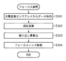
図3は、図1のプロジェクタが行うフォーカス調整処理の流れを示すフローチャートである。 FIG. 3 is a flowchart showing a flow of focus adjustment processing performed by the projector of FIG.
S301で、CPU108は、光電変換センサアレイ204及び205に結像した被検出物像による出力信号を読み込み、出力信号に基づいて光電変換センサアレイ204及び205それぞれにおける光強度分布を求められる。求められた光強度分布はCPU108内の記憶部に保存される。
In S301, the
S302で、CPU108は、光電変換センサアレイ204及び205の光強度分布から位相差を求める。位相差を求める方法としては、光電変換センサアレイ204及び205の光強度分布の類似度を評価する評価値を相関演算により算出し、評価値と光電変換センサアレイ204及び205で検出された像のズレの関係から位相差を求める方法がある。次に、CPU108は、外測三角測距方式に基づいて、投影面201までの距離を求める。
In S <b> 302, the
S303で、CPU108は、S302で求められた距離に基づき、フォーカスレンズ102の合焦位置までの繰り出し量を算出する。無限距離への投影時を基準とした場合、フォーカスレンズ102の繰り出し量Dは、投影面201までの距離をS、フォーカスレンズ102の焦点距離をFとすると、
D=1/(1/F−1/S)−F
で算出される。
In S303, the
D = 1 / (1 / F-1 / S) -F
Is calculated by
次に、投影された画像の指による指示について説明する。図4は、図1のプロジェクタが行う指検出処理の流れを示すフローチャートである。 Next, an instruction with a finger of the projected image will be described. FIG. 4 is a flowchart showing the flow of finger detection processing performed by the projector of FIG.
S401で、CPU108は、プロジェクタから投影している画像データを取得する。S402で、CPU108は、カメラ(不図示)で撮影した投影面201の画像データを取得する。S403で、CPU108は、S401で取得した画像データとS402で取得した画像データとを比較し、指検出(指先位置の検出を含む)処理を行う(指検出処理については、例えば特許文献2に記載の技術を利用可能である)。S404で、CPU108は、S403での検出結果を出力する。
In step S401, the
本発明の画像投影装置を移動電話に適用した実施例について説明する。図5は、実施例1に係る移動電話501の外観を示す図である。移動電話501は、プロジェクタ部503を備える。移動電話501はまた、一般的な電話機操作に使う操作釦508に加えて、プロジェクタ釦504とフォーカス調整釦502とを備える。プロジェクタ釦504はプロジェクタ部503のON/OFFを行うための釦である。フォーカス調整釦502は投影された画像のフォーカス調整を行う操作に用いる釦である。移動電話501はまた、投影面までの距離を測定するための測距センサ506と、指検出処理のために利用されるカメラ507とを備える。
An embodiment in which the image projection apparatus of the present invention is applied to a mobile phone will be described. FIG. 5 is a diagram illustrating an appearance of the
図6は、移動電話501の構成を示す機能ブロック図である。図6において、図5で示した要素と同一の要素には同一の符号を付し、その説明を省略する。フォーカス調整部605は、測距センサ506からの入力を利用してプロジェクタ部503を制御することにより、フォーカスを調整する。指操作検出部606(領域検出手段)は、カメラ507で撮影された画像と、プロジェクタ部503による投影対象の画像とを比較することにより、投影面上の画像の、投影面において指により指示された領域を検出する処理(指検出処理)を行う。なお、検出対象は指に限定されず、例えば、指示棒などの物体であってもよい。ユーザ入力処理部610は、フォーカス調整釦502やプロジェクタ釦504などの釦の操作を受け付け、操作された釦に応じた処理を行う。
FIG. 6 is a functional block diagram showing the configuration of the
GUI制御部607は、プロジェクタ部503による投影対象の画像(投影用画像)を生成する。表示メモリ604は、GUI制御部607が生成した投影用画像を格納する。通信制御部608は、アンテナ609を介して音声やデータなどの通信を行う。
The
図7は、移動電話501が実行する画像投影処理の流れを示すフローチャートである。プロジェクタ釦504が押下されるとプロジェクタ部503が起動し、その起動中に釦操作が行われると本フローチャートの処理が開始する。また、釦操作が行われなくても、例えばプロジェクタ部503の起動時などに本フローチャートの処理がS706から開始してもよい。
FIG. 7 is a flowchart showing the flow of image projection processing executed by the
S702で、ユーザ入力処理部610は、操作された釦がフォーカス調整釦502であるか否かを判定する。判定結果が「Yes」であればS706に進み、「No」であればS703に進む。
In step S <b> 702, the user
S706で、フォーカス調整部605は、測距センサ506を用いて投影面までの距離を測定し、フォーカス調整を行う(詳細については、図3及びその説明を参照)。S707で、GUI制御部607は、測定された距離が閾値未満であるか否かを判定する。閾値未満である場合はS708に進み、そうでない場合はS712に進む。この閾値は、ユーザが投影面に手が届くか否かを判断する指標として用いられる。即ち、投影面までの距離が閾値未満の場合はユーザが投影面に手が届く可能性が高いので、後述するように指操作用GUIが投影される。閾値は例えば70cmであるが、ユーザが閾値を設定可能なように移動電話501が構成されていてもよい。
In step S <b> 706, the
S708で、GUI制御部607は、プロジェクタ部503が指操作用GUI(第1画像)を投影中であるか否かを判定する。判定結果が「Yes」であればS711に進み、「No」であればS709に進む。
In step S <b> 708, the
S709で、GUI制御部607は、投影用画像として指操作用GUIを生成して表示メモリ604に格納する。S710で、GUI制御部607は、指操作検出部606を有効化する。
In step S <b> 709, the
図8の指操作用GUI801は、S709で生成される指操作用GUIの一例である。投影面までの距離が小さい場合は投影面上に表れる画像のサイズが比較的小さくなるので、視認性や操作性の向上を目的として、「終了」釦などの領域は比較的大きく生成される。図7には示されていないが、指操作検出部606は、図4に示した要領で指が指示する領域を検出し、ユーザ入力処理部610は、検出された領域に応じた処理(例えば、テレビ番組表811のスクロール)を実行する。また、GUI制御部607は、ユーザ入力処理部610による処理内容に基づいて、更新された指操作用GUIを生成する。
The
S711で、プロジェクタ部503は、表示メモリ604に格納されている投影用画像(S709を経由した場合は指操作用GUI)を投影する。
In step S <b> 711, the
S707において距離が閾値以上であると判定された場合、S712で、GUI制御部607は、プロジェクタ部503が釦操作用GUI(第2画像)を投影中であるか否かを判定する。判定結果が「Yes」であればS711に進み、「No」であればS713に進む。
If it is determined in S707 that the distance is greater than or equal to the threshold, in S712, the
S713で、GUI制御部607は、投影用画像として釦操作用GUIを生成して表示メモリ604に格納する。S714で、GUI制御部607は、指操作検出部606を無効化する。図8の釦操作用GUI802は、S713で生成される釦操作用GUIの一例である。釦操作用GUI802は、操作釦508などの釦の操作により移動するカーソルを持つ。また、投影面までの距離が大きい場合は投影面上に表れる画像のサイズが比較的大きくなるので、釦操作用GUI802は一般的に、指操作用GUI801よりも多くの情報を含む。
In step S <b> 713, the
S702においてフォーカス調整釦502以外の釦が操作されたと判定された場合、S703で、ユーザ入力処理部610は、プロジェクタ部503が釦操作用GUIを投影中であるか否かを判定する。判定結果が「Yes」であればS704に進み、「No」であれば処理を終了する。
If it is determined in S702 that a button other than the
S704で、ユーザ入力処理部610は、釦操作に応じた処理(例えば、カーソルの移動)を実行する。S705で、GUI制御部607は、S704における処理内容に基づいて、更新された釦操作用GUIを生成する。
In step S704, the user
ところで、S705において、GUI制御部607は、ユーザ入力処理部610による処理内容(即ち、更新された釦操作用GUIの状態)を記憶してもよい。同様に、GUI制御部607は、指操作用GUIの投影中にユーザ入力処理部610が実行した処理の内容も記憶してもよい。この場合、S709で、GUI制御部607は、釦操作用GUIの投影中に実行された処理の内容に基づいて指操作用GUIを生成することができる。また、S713で、GUI制御部607は、指操作用GUIの投影中に実行された処理の内容に基づいて釦操作用GUIを生成することができる。
By the way, in S705, the
これにより、GUIの種類が切り替わる場合に、切り替わりの前後でGUIの内容の連続性を維持することができる。例えば、図8の釦操作用GUI802では「PM3」の行、「BS103」の列にカーソルが存在する。そこで、この状態で切り替わりが発生すると、指操作用GUI801に示すように、「PM3」の行が上に、「BS103」の列が左に表れるように、指操作用GUIが生成される。
Thereby, when the type of GUI is switched, the continuity of the contents of the GUI can be maintained before and after switching. For example, in the
また、S710で指操作検出部606の有効化が行われ、S714で指操作検出部606の無効化が行われたが、指操作検出部606は常に有効であってもよい。即ち、移動電話501は、釦操作用GUIの投影中も、指による操作を受け付けてもよい。同様に、移動電話501は、指操作用GUIの投影中も、釦による操作を受け付けてもよい。
In addition, the finger
以上説明したように、本実施例によれば、移動電話501は投影面までの距離を考慮した画像を投影するので、ユーザの利便性が向上する。特に、画像投影装置から投影された画像に対する操作をユーザが行う場合に、ユーザに近い位置に投影した場合と、その場合に比べて遠い位置に投影した場合とでは、その投影面までの距離によって操作しやすい画像は異なる。上述したように、近い位置に投影した場合は、ユーザが指を使って画像に対する操作入力を行い、指が届かない位置に投影した場合には、何らかのポインティングデバイスを利用して画像に対する操作入力を行うのが好適である。従来の技術では、このような課題を解決できなかったが、本発明は上述した構成を採用したことで、画像投影装置から投影した画像を用いて操作入力を行う場合、投影面までの距離に応じた画像を生成して表示することで、当該課題を解決することができる。
As described above, according to the present embodiment, since the
(変形例1)
図9は、実施例1の変形例1に係る移動電話901の構成を示す機能ブロック図である。図9において、図6に示す要素と同一の要素には同一の符号を付し、説明を省略する。移動電話901は、持ち手センサ902を備える。持ち手センサ902は、ユーザが移動電話901を右手で持っているか左手で持っているかを判定する。
(Modification 1)
FIG. 9 is a functional block diagram illustrating a configuration of the
上述した画像投影処理では、変形例1では、図10を参照して以下に説明するように、GUI制御部607は、指操作用GUIを生成する際にユーザがどちらの手で移動電話901を持っているかを考慮する。
In the image projection processing described above, in Modification 1, as will be described below with reference to FIG. 10, the
図10は、図7のS709の処理に置き換わる処理を示す図である。また、図10の処理は、指操作用GUIの投影中に持ち手が変化したことを持ち手センサ902が検出した場合にも実行される。
FIG. 10 is a diagram showing a process that replaces the process of S709 of FIG. 10 is also executed when the
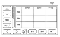
S1001で、GUI制御部607は、持ち手が右手であるか否かを判定する。右手であればS1002に進み、そうでなければS1003に進む。S1002で、GUI制御部607は、図11に示す指操作用GUI1101を生成する。指操作用GUI1101は、左手による操作に適したように構成されている。S1003で、GUI制御部607は、図8に示す指操作用GUI801を生成する。指操作用GUI801は、右手による操作に適したように構成されている。これにより、ユーザの利便性が更に向上する。
In step S1001, the
(変形例2)
図12は、実施例1の変形例2に係る移動電話1201の構成を示す機能ブロック図である。図12において、図6に示す要素と同一の要素には同一の符号を付し、説明を省略する。移動電話1201は、投影方向検出部1202(移動検出手段)、及び加速度センサ1203を備える。投影方向検出部1202は、加速度センサ1203からの情報に基づき、移動電話1201の移動を検出する。
(Modification 2)
FIG. 12 is a functional block diagram illustrating a configuration of the
投影方向検出部1202が移動を検出した場合、図7に示す画像投影処理が、S706から開始される。移動電話1201が移動すると投影面までの距離が変化する可能性があるが、変形例2によれば、変化後の距離に応じた画像が投影されるので、ユーザの利便性が更に向上する。
When the projection
[その他の実施例]
また、本発明は、以下の処理を実行することによっても実現される。即ち、上述した実施形態の機能を実現するソフトウェア(プログラム)を、ネットワーク又は各種記憶媒体を介してシステム或いは装置に供給し、そのシステム或いは装置のコンピュータ(またはCPUやMPU等)がプログラムを読み出して実行する処理である。
[Other Examples]
The present invention can also be realized by executing the following processing. That is, software (program) that realizes the functions of the above-described embodiments is supplied to a system or apparatus via a network or various storage media, and a computer (or CPU, MPU, or the like) of the system or apparatus reads the program. It is a process to be executed.
Claims (11)
前記画像投影装置から投影面までの距離を測定する測定手段と、
前記投影面に投影されている画像の領域であって、物体により指示された領域を検出する領域検出手段と、
ユーザによる操作を受け付ける操作手段と、
前記測定された距離が閾値未満の場合は前記領域検出手段に対応する第1の操作画像を生成し、前記測定された距離が前記閾値以上の場合は前記第1の操作画像とは異なる前記操作手段に対応する第2の操作画像を生成する生成手段と、
前記生成手段が生成した操作画像を前記投影面に投影する投影手段と、
を備えることを特徴とする画像投影装置。 An image projection device,
Measuring means for measuring the distance from the image projection device to the projection plane;
An area detection unit for detecting an area of the image projected on the projection plane, the area designated by the object;
An operation means for accepting an operation by a user;
When the measured distance is less than a threshold value, a first operation image corresponding to the region detection unit is generated, and when the measured distance is greater than or equal to the threshold value , the operation different from the first operation image is performed. Generating means for generating a second operation image corresponding to the means;
Projection means for projecting the operation image generated by the generation means onto the projection plane;
An image projection apparatus comprising:
ことを特徴とする請求項2に記載の画像投影装置。 The processing means executes processing according to an operation received by the operation means during projection of the second operation image.
The image projection apparatus according to claim 2, wherein:
前記生成手段は、前記第2の操作画像の投影中に前記処理手段が実行した処理の内容に基づいて前記第1の操作画像を生成し、前記第1の操作画像の投影中に前記処理手段が実行した処理の内容に基づいて前記第2の操作画像を生成する
ことを特徴とする請求項3に記載の画像投影装置。 Further comprising storage means for storing the contents of processing the processing means during projection is executed in the first operating image, and a content of processing the processing means during projection of the second operating image is executed,
The generation means generates the first operation image based on the content of processing executed by the processing means during the projection of the second operation image, and the processing means during the projection of the first operation image. The image projection apparatus according to claim 3, wherein the second operation image is generated based on a content of processing executed by the computer.
前記移動が検出された場合、前記測定手段は前記測定を実行する
ことを特徴とする請求項1から4のいずれか1項に記載の画像投影装置。 A movement detecting means for detecting movement of the image projection device;
5. The image projection apparatus according to claim 1, wherein when the movement is detected, the measurement unit performs the measurement.
前記画像投影装置から投影面までの距離を測定する測定工程と、
前記投影面に投影されている画像の領域であって、物体により指示された領域を検出する領域検出工程と、
ユーザによる操作を受け付ける操作工程と、
前記測定された距離が閾値未満の場合は前記領域検出工程に対応する第1の操作画像を生成し、前記測定された距離が前記閾値以上の場合は前記第1の操作画像とは異なる前記操作工程に対応する第2の操作画像を生成する生成工程と、
前記生成工程で生成した操作画像を前記投影面に投影する投影工程と、
を備えることを特徴とする制御方法。 A method for controlling an image projection apparatus, comprising:
A measuring step of measuring a distance from the image projection device to the projection plane;
An area detection step of detecting an area of an image projected on the projection plane, the area designated by an object;
An operation process for receiving an operation by a user;
When the measured distance is less than a threshold, a first operation image corresponding to the region detection step is generated, and when the measured distance is greater than or equal to the threshold , the operation is different from the first operation image. A generation step of generating a second operation image corresponding to the step;
A projection step of projecting the operation image generated in the generation step onto the projection plane;
A control method comprising:
ことを特徴とする請求項8に記載の制御方法。 The control method according to claim 8.
前記生成工程では、前記第2の操作画像の投影中に前記処理工程で実行した処理の内容に基づいて前記第1の操作画像を生成し、前記第1の操作画像の投影中に前記処理工程で実行した処理の内容に基づいて前記第2の操作画像を生成する In the generation step, the first operation image is generated based on the content of the processing executed in the processing step during the projection of the second operation image, and the processing step is performed during the projection of the first operation image. The second operation image is generated based on the content of the processing executed in step
ことを特徴とする請求項9に記載の制御方法。 The control method according to claim 9.
前記移動が検出された場合、前記測定工程において前記測定を実行する If the movement is detected, the measurement is performed in the measurement process.
ことを特徴とする請求項7から10のいずれか1項に記載の制御方法。 The control method according to any one of claims 7 to 10, wherein:
Priority Applications (3)
| Application Number | Priority Date | Filing Date | Title |
|---|---|---|---|
| JP2009161237A JP5553546B2 (en) | 2009-07-07 | 2009-07-07 | Image projection apparatus and control method thereof |
| US12/784,114 US8220936B2 (en) | 2009-07-07 | 2010-05-20 | Image projection apparatus with operation image generation based on distance to the projection surface, and method for controlling the same |
| US13/524,723 US8851685B2 (en) | 2009-07-07 | 2012-06-15 | Image display apparatus for displaying GUI image and method for controlling the same |
Applications Claiming Priority (1)
| Application Number | Priority Date | Filing Date | Title |
|---|---|---|---|
| JP2009161237A JP5553546B2 (en) | 2009-07-07 | 2009-07-07 | Image projection apparatus and control method thereof |
Publications (3)
| Publication Number | Publication Date |
|---|---|
| JP2011019018A JP2011019018A (en) | 2011-01-27 |
| JP2011019018A5 JP2011019018A5 (en) | 2012-08-23 |
| JP5553546B2 true JP5553546B2 (en) | 2014-07-16 |
Family
ID=43427185
Family Applications (1)
| Application Number | Title | Priority Date | Filing Date |
|---|---|---|---|
| JP2009161237A Expired - Fee Related JP5553546B2 (en) | 2009-07-07 | 2009-07-07 | Image projection apparatus and control method thereof |
Country Status (2)
| Country | Link |
|---|---|
| US (2) | US8220936B2 (en) |
| JP (1) | JP5553546B2 (en) |
Families Citing this family (9)
| Publication number | Priority date | Publication date | Assignee | Title |
|---|---|---|---|---|
| US8890650B2 (en) * | 2009-05-29 | 2014-11-18 | Thong T. Nguyen | Fluid human-machine interface |
| JP5834615B2 (en) * | 2011-08-18 | 2015-12-24 | 株式会社リコー | PROJECTOR, ITS CONTROL METHOD, ITS PROGRAM, AND RECORDING MEDIUM CONTAINING THE PROGRAM |
| CN104185824B (en) * | 2012-03-31 | 2019-01-22 | 英特尔公司 | The calculating unit and system of projection for showing and integrating |
| JP6040564B2 (en) | 2012-05-08 | 2016-12-07 | ソニー株式会社 | Image processing apparatus, projection control method, and program |
| CN103929605B (en) | 2014-04-01 | 2018-06-08 | 北京智谷睿拓技术服务有限公司 | Control method is presented in image and control device is presented in image |
| CN103929606B (en) | 2014-04-01 | 2017-10-10 | 北京智谷睿拓技术服务有限公司 | Control method is presented in image and control device is presented in image |
| WO2017161270A1 (en) * | 2016-03-17 | 2017-09-21 | Design Mill Inc. | Interactive imaging and sensing system, device and method |
| US11236897B2 (en) | 2016-03-17 | 2022-02-01 | Design Mill Inc. | Interactive imaging and sensing system, device and method |
| CN112040206A (en) | 2020-08-21 | 2020-12-04 | 广景视睿科技(深圳)有限公司 | Zooming projection method and projector |
Family Cites Families (21)
| Publication number | Priority date | Publication date | Assignee | Title |
|---|---|---|---|---|
| JPH0259691A (en) * | 1988-08-25 | 1990-02-28 | Matsushita Electric Ind Co Ltd | Projection relation detecting device |
| JP3968477B2 (en) * | 1997-07-07 | 2007-08-29 | ソニー株式会社 | Information input device and information input method |
| US6720949B1 (en) * | 1997-08-22 | 2004-04-13 | Timothy R. Pryor | Man machine interfaces and applications |
| JP3794180B2 (en) * | 1997-11-11 | 2006-07-05 | セイコーエプソン株式会社 | Coordinate input system and coordinate input device |
| DE19845030A1 (en) * | 1998-09-30 | 2000-04-20 | Siemens Ag | Imaging system for reproduction of medical image information |
| JP3804302B2 (en) * | 1998-11-11 | 2006-08-02 | セイコーエプソン株式会社 | Display device and information recording medium |
| US6592228B1 (en) * | 1999-12-24 | 2003-07-15 | Matsushita Electric Industrial Co., Ltd | Projector comprising a microcomputer for controlling zoom and focus adjustments utilizing pattern generation and calculation means |
| US7138983B2 (en) * | 2000-01-31 | 2006-11-21 | Canon Kabushiki Kaisha | Method and apparatus for detecting and interpreting path of designated position |
| DE10007891C2 (en) * | 2000-02-21 | 2002-11-21 | Siemens Ag | Method and arrangement for interacting with a representation visible in a shop window |
| US6775014B2 (en) * | 2001-01-17 | 2004-08-10 | Fujixerox Co., Ltd. | System and method for determining the location of a target in a room or small area |
| US7259747B2 (en) * | 2001-06-05 | 2007-08-21 | Reactrix Systems, Inc. | Interactive video display system |
| US8300042B2 (en) * | 2001-06-05 | 2012-10-30 | Microsoft Corporation | Interactive video display system using strobed light |
| US6802611B2 (en) * | 2002-10-22 | 2004-10-12 | International Business Machines Corporation | System and method for presenting, capturing, and modifying images on a presentation board |
| US7576727B2 (en) * | 2002-12-13 | 2009-08-18 | Matthew Bell | Interactive directed light/sound system |
| DE10260305A1 (en) * | 2002-12-20 | 2004-07-15 | Siemens Ag | HMI setup with an optical touch screen |
| JP4533641B2 (en) | 2004-02-20 | 2010-09-01 | オリンパス株式会社 | Portable projector |
| JP4657060B2 (en) * | 2005-08-25 | 2011-03-23 | シャープ株式会社 | projector |
| JP2007078821A (en) * | 2005-09-12 | 2007-03-29 | Casio Comput Co Ltd | Projector, projecting method and program |
| JP2008152622A (en) * | 2006-12-19 | 2008-07-03 | Mitsubishi Electric Corp | Pointing device |
| JP2008203490A (en) * | 2007-02-20 | 2008-09-04 | Seiko Epson Corp | Projector |
| JP4991458B2 (en) * | 2007-09-04 | 2012-08-01 | キヤノン株式会社 | Image display apparatus and control method thereof |
-
2009
- 2009-07-07 JP JP2009161237A patent/JP5553546B2/en not_active Expired - Fee Related
-
2010
- 2010-05-20 US US12/784,114 patent/US8220936B2/en not_active Expired - Fee Related
-
2012
- 2012-06-15 US US13/524,723 patent/US8851685B2/en active Active
Also Published As
| Publication number | Publication date |
|---|---|
| US20120249501A1 (en) | 2012-10-04 |
| US8220936B2 (en) | 2012-07-17 |
| JP2011019018A (en) | 2011-01-27 |
| US8851685B2 (en) | 2014-10-07 |
| US20110007227A1 (en) | 2011-01-13 |
Similar Documents
| Publication | Publication Date | Title |
|---|---|---|
| JP5553546B2 (en) | Image projection apparatus and control method thereof | |
| KR101505206B1 (en) | Optical finger navigation utilizing quantized movement information | |
| US9251722B2 (en) | Map information display device, map information display method and program | |
| US9621791B2 (en) | Imaging apparatus and control method to set an auto focus mode or an auto photometry mode corresponding to a touch gesture | |
| US9785244B2 (en) | Image projection apparatus, system, and image projection method | |
| US9033516B2 (en) | Determining motion of projection device | |
| US20090146968A1 (en) | Input device, display device, input method, display method, and program | |
| US8310652B2 (en) | Image taking system and lens apparatus | |
| TWI520033B (en) | Optical navigation utilizing speed based algorithm selection | |
| TW201415291A (en) | Method and system for gesture identification based on object tracing | |
| JP2010117917A (en) | Motion detection apparatus and operation system | |
| US11073949B2 (en) | Display method, display device, and interactive projector configured to receive an operation to an operation surface by a hand of a user | |
| JP2015022208A5 (en) | ||
| JP5825921B2 (en) | Display device and control method thereof | |
| KR102070598B1 (en) | Camera apparatus and method for controlling thereof | |
| JP5888986B2 (en) | Image processing apparatus and control method thereof | |
| JP2012215632A (en) | Lens device and operation control method thereof | |
| JP2018018308A (en) | Information processing device and control method and computer program therefor | |
| JP6409919B2 (en) | Input display device | |
| KR20130021642A (en) | Method for adjusting focus in mobile terminal having projector module and the mobile terminal therefor | |
| KR101530517B1 (en) | User terminal performable shooting function and method for adjusting location of shooting icon of the user terminal | |
| JP2021005168A (en) | Image processing apparatus, imaging apparatus, control method of image processing apparatus, and program | |
| JP7277247B2 (en) | Electronic device and its control method | |
| JP2013156925A (en) | Electronic apparatus, electronic apparatus control method, program, and storage medium | |
| JP7317567B2 (en) | Electronics |
Legal Events
| Date | Code | Title | Description |
|---|---|---|---|
| A521 | Request for written amendment filed |
Free format text: JAPANESE INTERMEDIATE CODE: A523 Effective date: 20120704 |
|
| A621 | Written request for application examination |
Free format text: JAPANESE INTERMEDIATE CODE: A621 Effective date: 20120704 |
|
| A977 | Report on retrieval |
Free format text: JAPANESE INTERMEDIATE CODE: A971007 Effective date: 20130806 |
|
| A131 | Notification of reasons for refusal |
Free format text: JAPANESE INTERMEDIATE CODE: A131 Effective date: 20130906 |
|
| TRDD | Decision of grant or rejection written | ||
| A01 | Written decision to grant a patent or to grant a registration (utility model) |
Free format text: JAPANESE INTERMEDIATE CODE: A01 Effective date: 20140428 |
|
| A61 | First payment of annual fees (during grant procedure) |
Free format text: JAPANESE INTERMEDIATE CODE: A61 Effective date: 20140527 |
|
| R151 | Written notification of patent or utility model registration |
Ref document number: 5553546 Country of ref document: JP Free format text: JAPANESE INTERMEDIATE CODE: R151 |
|
| LAPS | Cancellation because of no payment of annual fees |