JP5100088B2 - Exposure apparatus and device manufacturing method - Google Patents
Exposure apparatus and device manufacturing method Download PDFInfo
- Publication number
- JP5100088B2 JP5100088B2 JP2006302137A JP2006302137A JP5100088B2 JP 5100088 B2 JP5100088 B2 JP 5100088B2 JP 2006302137 A JP2006302137 A JP 2006302137A JP 2006302137 A JP2006302137 A JP 2006302137A JP 5100088 B2 JP5100088 B2 JP 5100088B2
- Authority
- JP
- Japan
- Prior art keywords
- substrate
- exposure
- shutter
- light
- illumination light
- Prior art date
- Legal status (The legal status is an assumption and is not a legal conclusion. Google has not performed a legal analysis and makes no representation as to the accuracy of the status listed.)
- Active
Links
Images


Classifications
-
- G—PHYSICS
- G03—PHOTOGRAPHY; CINEMATOGRAPHY; ANALOGOUS TECHNIQUES USING WAVES OTHER THAN OPTICAL WAVES; ELECTROGRAPHY; HOLOGRAPHY
- G03B—APPARATUS OR ARRANGEMENTS FOR TAKING PHOTOGRAPHS OR FOR PROJECTING OR VIEWING THEM; APPARATUS OR ARRANGEMENTS EMPLOYING ANALOGOUS TECHNIQUES USING WAVES OTHER THAN OPTICAL WAVES; ACCESSORIES THEREFOR
- G03B27/00—Photographic printing apparatus
- G03B27/72—Controlling or varying light intensity, spectral composition, or exposure time in photographic printing apparatus
-
- G—PHYSICS
- G03—PHOTOGRAPHY; CINEMATOGRAPHY; ANALOGOUS TECHNIQUES USING WAVES OTHER THAN OPTICAL WAVES; ELECTROGRAPHY; HOLOGRAPHY
- G03F—PHOTOMECHANICAL PRODUCTION OF TEXTURED OR PATTERNED SURFACES, e.g. FOR PRINTING, FOR PROCESSING OF SEMICONDUCTOR DEVICES; MATERIALS THEREFOR; ORIGINALS THEREFOR; APPARATUS SPECIALLY ADAPTED THEREFOR
- G03F7/00—Photomechanical, e.g. photolithographic, production of textured or patterned surfaces, e.g. printing surfaces; Materials therefor, e.g. comprising photoresists; Apparatus specially adapted therefor
- G03F7/70—Microphotolithographic exposure; Apparatus therefor
- G03F7/70483—Information management; Active and passive control; Testing; Wafer monitoring, e.g. pattern monitoring
- G03F7/7055—Exposure light control in all parts of the microlithographic apparatus, e.g. pulse length control or light interruption
- G03F7/70558—Dose control, i.e. achievement of a desired dose
-
- G—PHYSICS
- G03—PHOTOGRAPHY; CINEMATOGRAPHY; ANALOGOUS TECHNIQUES USING WAVES OTHER THAN OPTICAL WAVES; ELECTROGRAPHY; HOLOGRAPHY
- G03F—PHOTOMECHANICAL PRODUCTION OF TEXTURED OR PATTERNED SURFACES, e.g. FOR PRINTING, FOR PROCESSING OF SEMICONDUCTOR DEVICES; MATERIALS THEREFOR; ORIGINALS THEREFOR; APPARATUS SPECIALLY ADAPTED THEREFOR
- G03F7/00—Photomechanical, e.g. photolithographic, production of textured or patterned surfaces, e.g. printing surfaces; Materials therefor, e.g. comprising photoresists; Apparatus specially adapted therefor
- G03F7/70—Microphotolithographic exposure; Apparatus therefor
- G03F7/708—Construction of apparatus, e.g. environment aspects, hygiene aspects or materials
- G03F7/7085—Detection arrangement, e.g. detectors of apparatus alignment possibly mounted on wafers, exposure dose, photo-cleaning flux, stray light, thermal load
Abstract
Description
本発明は、光源からの照明光で原版を照明し該原版のパターンを投影光学系によって基板に投影して該基板を露光する露光装置、及び、該露光装置を利用してデバイスを製造するデバイス製造方法に関する。 The present invention relates to an exposure apparatus that illuminates an original with illumination light from a light source, projects a pattern on the original onto a substrate by a projection optical system, and exposes the substrate, and a device that manufactures a device using the exposure apparatus It relates to a manufacturing method.
特許文献1には、被記録体からの光又は被記録体に照射される光の強度を光電検出器で検出し、この検出値に対応する周波数の出力パルスを得て、このパルスを計数し、所定のパルス数に達した際にシャッタを閉じる構成を有する露光装置が記載されている。シャッタは、1枚の回転円板に遮光部と透光部を交互に設け、これを回転駆動することにより、照明光の遮光状態および透光状態を制御するものである。シャッタの作動遅れ時間、すなわちシャッタの閉じ信号が発生してからシャッタが完全に閉じるまでに被写体に照射される露光量による誤差を補正する必要がある。そのために、シャッタ開動作時にシャッタ作動遅れによる露光量に対応したパルス数を計数し、このパルス数を考慮してシャッタ閉じ信号の発生タイミングが補正される。
In
低露光量による露光制御を行う場合においては、特許文献1に記載されたような構成では、シャッタを閉じるタイミングが間に合わないことがある。そこで、パルス数を計数することなくシャッタを閉じる方法、光強度を低下させた状態で上記のようにパルス数を計数し、所定のパルス数に達した際にシャッタを閉じる方法が採用されうる。ここで、光強度を低下させる方法としては、光源位置を光軸方向に移動させる方法、減光フィルターを光源と被記録体との間に挿入する方法が考えられる。
しかしながら、パルス数を計数することなくシャッタを閉じる方法では、適正な露光量でウエハ或いはショット領域が露光されることを保証するための技術が必要である。また、上記のように光強度を低下させた状態で露光制御を行う方法ではスループットが低下するという欠点がある。 However, the method of closing the shutter without counting the number of pulses requires a technique for ensuring that the wafer or shot area is exposed with an appropriate exposure amount. In addition, the method of performing exposure control in a state where the light intensity is reduced as described above has a drawback that the throughput is reduced.
本発明は、上記のような課題認識を契機としてなされたものであり、例えば、高いスループットと正確な露光量制御を実現することを目的とする。 The present invention has been made in response to the above problem recognition, and an object thereof is to realize, for example, high throughput and accurate exposure amount control.
本発明の第1の側面は、光源からの照明光で原版を照明し該原版のパターンを投影光学系によって基板に投影して該基板を露光する露光装置に係り、前記露光装置は、前記原版への前記照明光の入射を制御するための回転シャッタと、前記照明光の光強度を検出する光センサと、前記回転シャッタの動作を制御する制御部とを備え、前記制御部は、第1光強度の照明光を使用して第1基板の複数ショット領域を露光する第1露光モードでは、前記光センサの出力に基づいて前記回転シャッタを閉じるタイミングを制御するとともに、前記回転シャッタの開放時間を記憶し、前記第1光強度よりも強い第2光強度の照明光を使用して前記第1基板に対して後続の第2基板の複数ショット領域を露光する第2露光モードでは、各ショット領域の目標露光量と、前記開放時間に基づいて得られる各ショット領域の補正情報とに基づいて決定される回転速度で前記回転シャッタを回転させ、これによって前記回転シャッタを閉状態から開状態にさせ、更に閉状態にさせる。 A first aspect of the present invention relates to an exposure apparatus that illuminates an original with illumination light from a light source, projects a pattern of the original onto a substrate by a projection optical system, and exposes the substrate. The exposure apparatus includes the original A rotary shutter for controlling the incidence of the illumination light on the optical sensor, a light sensor for detecting the light intensity of the illumination light, and a control unit for controlling the operation of the rotary shutter. In the first exposure mode in which illumination light having a light intensity is used to expose a plurality of shot areas of the first substrate, the timing for closing the rotary shutter is controlled based on the output of the optical sensor, and the opening time of the rotary shutter is set. In the second exposure mode, each shot is exposed to a plurality of shot regions of the subsequent second substrate with respect to the first substrate using illumination light having a second light intensity higher than the first light intensity. Area eyes Rotating the rotary shutter at a rotational speed determined based on an exposure amount and correction information of each shot area obtained based on the opening time, thereby causing the rotary shutter to be opened from a closed state; Let it be closed.
本発明の第2の側面は、光源からの照明光で原版を照明し該原版のパターンを投影光学系によって基板に投影して該基板を露光する露光装置に係り、前記露光装置は、前記原版への前記照明光の入射を制御するための回転シャッタと、前記照明光の光強度を検出する光センサと、前記回転シャッタの動作を制御する制御部とを備え、前記制御部は、第1光強度の照明光を使用して第1基板の複数ショット領域を露光する第1露光モードでは、前記光センサの出力に基づいて前記回転シャッタを閉じるタイミングを制御するとともに、前記回転シャッタの開放時間を記憶し、前記第1光強度よりも強い第2光強度の照明光を使用して前記第1基板に対して後続の第2基板の複数ショット領域を露光する第2露光モードでは、各ショット領域の目標露光量と、前記開放時間に基づいて得られる各ショット領域の補正情報を含む複数の補正係数とに基づいて決定される回転速度で前記回転シャッタを回転させ、これによって前記回転シャッタを閉状態から開状態にさせ、更に閉状態にさせる。 A second aspect of the present invention relates to an exposure apparatus that illuminates an original with illumination light from a light source, projects a pattern on the original onto a substrate by a projection optical system, and exposes the substrate. The exposure apparatus includes the original A rotary shutter for controlling the incidence of the illumination light on the optical sensor, a light sensor for detecting the light intensity of the illumination light, and a control unit for controlling the operation of the rotary shutter. In the first exposure mode in which illumination light having a light intensity is used to expose a plurality of shot areas of the first substrate, the timing for closing the rotary shutter is controlled based on the output of the optical sensor, and the opening time of the rotary shutter is set. In the second exposure mode, each shot is exposed to a plurality of shot regions of the subsequent second substrate with respect to the first substrate using illumination light having a second light intensity higher than the first light intensity. Area eyes The rotary shutter is rotated at a rotation speed determined based on an exposure amount and a plurality of correction coefficients including correction information of each shot area obtained based on the opening time, and thereby the rotary shutter is moved from the closed state. Open and then close.
本発明によれば、例えば、高いスループットと正確な露光量制御を実現することができる。 According to the present invention, for example, high throughput and accurate exposure amount control can be realized.
以下、添付図面を参照しながら本発明の好適な実施形態を説明する。 Hereinafter, preferred embodiments of the present invention will be described with reference to the accompanying drawings.
図1は、本発明の好適な実施形態の露光装置の概略構成を示す図である。本発明の好適な実施形態の露光装置100は、光源1、シャッタ4、原版ステージ21、投影光学系6、基板ステージ22を備える。原版ステージ21は、原版(レチクル)2を保持し位置決めする。原版2には、半導体回路パターン等のパターンが形成されていて、光源1が発生する照明光によって照明される。基板ステージ22は、フォトレジスト(感光剤)が塗布された基板(ウエハ)3を保持し位置決めする。基板3には、投影光学系6を介して、原版2のパターンが投影され、これにより基板3に塗布されているフォトレジストに潜像パターンが形成される。潜像パターンは、現像装置において現像され、これによりレジストパターンが形成される。
FIG. 1 is a view showing the schematic arrangement of an exposure apparatus according to a preferred embodiment of the present invention. An
シャッタ4は、光源1と原版ステージ21との間に配置され、原版2への光源1からの照明光の入射時間を制御することによって基板3の露光時間を決定する。露光装置100は、基板3の露光量を検知する露光量センサSを備える。露光量センサSは、例えば、光センサ5、アンプ7、V/Fコンバータ9、パルスカウンタ11を含んで構成されうる。光センサ5は、シャッタ4と原版ステージ21との間における照明光の強度を検出する。光センサ5は、受光素子を含む。該受光素子は、シャッタ4と原版ステージ21との間における照明光の光路に配置されてもよいし、該光路からミラーによって取り出された光を受光するように配置されてもよい。アンプ7は、光センサ5から出力される光強度を示す信号を電圧信号に変換する。V/Fコンバータ9は、アンプ7から出力される電圧信号を周波数信号に変換する。パルスカウンタ11は、V/Fコンバータ9から出力される周波数信号のパルス数をカウントする。パルスカウンタ11によってカウントされたカウント値は、照明光の光強度を積算した量を意味するので、基板の露光量と比例する。よって、このカウント値によって基板の露光量を示す情報が得られる。
The
露光装置100は、更に、制御部13、入出力装置15、目標露光量決定器16、シャッタ駆動回路14等を備えうる。制御部13は、あるモードにおいては、パルスカウンタ11の出力に基づいて露光量を制御する。シャッタ駆動回路14は、制御部13からの指示を受けてシャッタ4を開閉駆動する。入出力装置(コンソール)15は、各種の情報を入力・出力するための装置である。目標露光量決定器16は、入出力装置15を介して入力された露光条件、及び、必要に応じて入力される他の情報に基づいて、目標露光量を決定する。
The
図2は、シャッタ4の動作による露光制御を説明するための図である。シャッタ4は、シャッタ板81を含む。図2では、シャッタ板81と、照明光が通る光路領域86との位置関係が例示されている。図2(a)は、シャッタ板81の遮光部Aによって光路領域86が遮断された状態である。図2(b)は、図2(a)の状態からシャッタ板81が時計回りに60°回転し、光路領域86が遮断されなくなった状態である。図2(c)は、図2(b)の状態からシャッタ板81が更に時計回りに60°回転し、遮光部Bにより光路領域86が遮断された状態である。光路領域86が遮断されていない状態は、シャッタ4が開かれた状態であり、光路領域86が遮断された状態は、シャッタ4が閉じられた状態である。
FIG. 2 is a view for explaining exposure control by the operation of the
この実施形態では、低露光量で基板を露光する際の露光シーケンスは、第1光強度の照明光を使用する低速露光モード(第1露光モード)と、第1光強度よりも強い第2光強度の照明光を使用する高速露光モード(第2露光モード)とを含む。高速露光モードは、低速露光モードに続いて実行される。 In this embodiment, the exposure sequence when exposing the substrate with a low exposure amount includes a low-speed exposure mode (first exposure mode) using illumination light having a first light intensity, and a second light stronger than the first light intensity. And a high-speed exposure mode (second exposure mode) using intense illumination light. The high-speed exposure mode is executed following the low-speed exposure mode.
低速露光モードは、複数の基板からなるロットの先頭の少なくとも1枚の基板について実施されうる。低速露光モードでは、基板に入射する光の強度を低下させた状態で、V/Fコンバータ9から出力される周波数信号のパルス数をパルスカウンタ11でカウントし、カウントしてパルス数が目標パルス数に達した時点でシャッタ4を閉じる。ここで、光強度を第1光強度に低下させる方法としては、光源1の位置を光軸方向に変更する方法、減光フィルターを光源と原版との間に挿入する方法が考えられる。
The low-speed exposure mode can be performed on at least one substrate at the head of a lot made up of a plurality of substrates. In the low-speed exposure mode, the number of pulses of the frequency signal output from the V /
高速露光モードは、低速露光モードで露光された基板に対して後続の基板を対象とする。例えば、低速露光モードでロットの1枚目の基板が露光された場合は、高速露光モードでは、ロットの2枚目以降の基板を対象として露光を行う。高速露光モードでは、露光量センサSの出力を用いず、また、光強度を低下させることなく、目標露光量と低速露光モードでの露光制御に基づいて得られる補正情報とに基づいて決定される回転速度でシャッタ4が回転駆動されて露光量が制御される。ここで、1ショット領域の露光において、図2(a)に示すように遮光部Aによって光路領域86が完全に遮断された状態から、図2(c)に示すようにシャッタ4が120°回転駆動される。露光時間は、遮光部Aによる光路領域86の遮断が終了してから遮光部Bによる光路領域86の遮断が開始されるまでの時間であり、この時間は、シャッタ4の回転速度で決定される。
The high-speed exposure mode targets a substrate subsequent to the substrate exposed in the low-speed exposure mode. For example, when the first substrate of the lot is exposed in the low-speed exposure mode, the exposure is performed on the second and subsequent substrates in the lot in the high-speed exposure mode. In the high-speed exposure mode, it is determined based on the target exposure amount and the correction information obtained based on the exposure control in the low-speed exposure mode without using the output of the exposure amount sensor S and without reducing the light intensity. The
図3は、目標露光量とシャッタ4の回転速度(シャッタ板81の回転速度)との関係を例示するグラフである。図3に例示されるような目標露光量とシャッタ4の回転速度との関係は、実験又は計算により求めることができ、例えば、近似関数又はデータテーブルとして制御部13内のメモリ(不図示)に予め格納しておくことができる。以下、特に言及しない限り、「メモリ」は、制御部13内のメモリを意味するが、このようなメモリに代えて、制御部13の外部装置としてのメモリを使用しうることは言うまでもない。
FIG. 3 is a graph illustrating the relationship between the target exposure amount and the rotation speed of the shutter 4 (rotation speed of the shutter plate 81). The relationship between the target exposure amount and the rotation speed of the
図4は、基板上におけるショットレイアウトを例示する図である。基板3上に格子状に配列された領域は、ショット領域と呼ばれる分割露光領域を示す。ショット領域中に記載された数字は、露光順番を示す。
FIG. 4 is a diagram illustrating a shot layout on the substrate. The regions arranged in a lattice pattern on the
図5は、露光シーケンスを実行する前の露光装置100における判断処理を示すフローチャートである。
FIG. 5 is a flowchart showing determination processing in the
ステップS101では、制御部13は、入出力装置15を介して入力又は設定された切替基準を取得する。ステップS103では、制御部13は、目標露光量決定器16から目標露光量情報(TargetDose)を取得する。
In step S <b> 101, the
ステップS104では、制御部13は、ステップS102で取得した切替基準とステップS103で取得した目標露光量とを比較し、目標露光量が切替基準より大きければ、ステップS105に処理を進め、高露光量モードにおける露光シーケンスを実行する。一方、目標露光量が切替基準と等しいか小さければ、制御部13は、処理をステップS106に進め、低露光量モードにおける露光シーケンスを実行する。
In step S104, the
図6は、高露光量モードにおける露光シーケンスを示すフローチャートである。ステップS202では、制御部13は、目標露光量決定器16から提供された目標露光量をメモリに格納、即ち記憶する。ステップS203では、制御部13は、シャッタ駆動回路14に対してシャッタ開指令を送ってシャッタ4を開かせる。
FIG. 6 is a flowchart showing an exposure sequence in the high exposure mode. In step S202, the
ステップS204では、シャッタ4が開いて光源1が発生した照明光で原版2が照明されることによって基板3の露光が開始される。光センサ5から出力される光強度を示す信号は、アンプ7で電圧信号に変換され、この電圧信号は、V/Fコンバータ9によりパルス列に変換され、このパルス数は、パルスカウンタ11によってカウントされる。
In step S204, exposure of the
ステップS205では、制御部13は、パルスカウンタ11から提供されるカウント値を読み、カウント値が前述のメモリに格納した目標露光量によって決まるパルス値と一致するか否かを判断する。ステップS205は、パルスカウンタ11から提供されるカウント値が目標露光量によって決まるパルス値と一致するまで繰り返され、両者が一致したら、制御部13は、ステップS206に処理を進める。
In step S205, the
ステップS206では、制御部13は、シャッタ駆動回路14に対してシャッタ閉指令を送り、シャッタ4を閉じさせる。
In step S <b> 206, the
図7は、低露光量モードにおける露光シーケンスを示すフローチャートである。ステップS302では、制御部13は、処理対象の基板が低速露光モードによる露光の対象であるか否かを判断する。ここで、低速露光モードによる露光の対象の基板は、典型的には、ロットの先頭の少なくとも1枚の基板である。低速露光モードによる露光の対象の基板をどのような基板にすべきであるかは、例えば、入出力装置15を介して入力される情報に応じて決定されうる。或いは、低速露光モードによる露光の対象の基板をどのような基板にすべきであるかは、デフォルトで設定された情報に従いうる。低速露光モードによる露光の対象の基板として、上記の他、例えば、露光装置100におけるステータスが変動したこと(例えば、光源1の稼働時間が基準値を超えたなど)に応じて、その後に処理されるべき少なくとも1枚の基板が選択されてもよい。
FIG. 7 is a flowchart showing an exposure sequence in the low exposure amount mode. In step S302, the
制御部13は、処理すべき基板が低速露光の対象の基板である場合には、処理をステップS303に進め、処理すべき基板が低速露光の対象の基板ではない場合には、処理をステップS304に進める。
If the substrate to be processed is a substrate subject to low-speed exposure, the
図8は、低速露光モード(第1露光モード)における露光シーケンスを示すフローチャートである。図8に示す処理の開始時に、ショット番号(N)は、1に初期化されるものとする。 FIG. 8 is a flowchart showing an exposure sequence in the low-speed exposure mode (first exposure mode). It is assumed that the shot number (N) is initialized to 1 at the start of the processing shown in FIG.
ステップS402では、制御部13は、基板に入射する光の強度を第1光強度に低下させる。ここで、光の強度を低下させる方法としては、前述のように、例えば、光源1の位置を光軸方向に変更する方法、減光フィルターを光源と原版との間に挿入する方法が考えられる。光の強度は、露光量センサSの出力に基づいてシャッタ4を閉じることによって目標露光量を実現することが可能になるように低下される。
In step S402, the
シャッタ4の十分な開放時間が得られると、露光量センサSの出力に基づいて制御部13がシャッタ駆動回路14に対してシャッタ閉指令を送ってシャッタ4を閉じさせる方法で基板を適正露光量で露光することができる。
When a sufficient opening time of the
ステップS403では、制御部13は、目標露光量決定器16から提供された目標露光量をメモリに格納する。ステップS404では、制御部13は、シャッタ駆動回路14に対してシャッタ開指令を送ってシャッタ4を開かせる。
In step S403, the
ステップS405では、シャッタ4が開いて光源1が発生した照明光で原版2が照明されることによって基板3の露光が開始される。光センサ5から出力される光強度を示す信号は、アンプ7で電圧信号に変換され、この電圧信号は、V/Fコンバータ9によりパルス列に変換され、このパルス数は、パルスカウンタ11によってカウントされる。
In step S405, the exposure of the
ステップS406では、制御部13は、露光量センサSのパルスカウンタ11から提供されるカウント値を読み、カウント値が前述のメモリに格納した目標露光量によって決まるパルス値と一致するか否かが判断される。ステップS406は、パルスカウンタ11から提供される計数値が目標露光量によって決まるパルス値と一致するまで繰り返され、両者が一致したら、制御部13は、ステップS407に処理を進める。
In step S406, the
ステップS407では、制御部13は、シャッタ駆動回路14に対してシャッタ閉指令を送ってシャッタ4を閉じさせる。すなわち、シャッタ4が閉じるタイミングは、露光量センサSのパルスカウンタ11から提供されるカウント値に基づいて制御部13によって制御される。
In step S407, the
ステップS408では、制御部13は、シャッタ開指令(ステップS404)からシャッタ閉指令(ステップS407)までにかかった時間をシャッタ開放時間(ShutterOpenTime)としてメモリに格納する。
In step S408, the
ステップ409では、制御部13は、ステップS403で格納した目標露光量(TargetDose)とステップS408で格納したシャッタ開放時間(ShutterOpenTime)とに基づいて、式(1)に従って補正係数(補正情報)を算出する。ステップS410では、制御部13は、算出した補正係数を、ショット番号(N)を配列変数とする第2補正係数(Coef2(N))として、メモリに格納する。
In step 409, the
Coef2(N)= ShutterOpenTime × TimeDoseConst / TargetDose ・・・(1)
ここで、Nはショット番号、TargetDoseは目標露光量[J/m2]、ShutterOpenTimeはシャッタ開放時間[S]である。また、TimeDoseConstは比例定数[J/m2・S]、Coef2(N)は第2補正係数である。
Coef2 (N) = ShutterOpenTime × TimeDoseConst / TargetDose (1)
Here, N is a shot number, TargetDose is a target exposure amount [J / m 2 ], and ShutterOpenTime is a shutter opening time [S]. TimeDoseConst is a proportionality constant [J / m 2 · S], and Coef2 (N) is a second correction coefficient.
ステップS411では、制御部13は、全ショット領域について露光がなされたか否かを判断し、全ショット領域について露光がなされていない場合には、ショット番号(N)を1だけ増加させて処理をステップS404に戻す。
In step S411, the
なお、低速露光モードによる露光の対象が複数枚の基板である場合には、複数枚の基板についてそれぞれ得られる第2補正係数を演算(例えば、平均の演算)して、この演算結果に基づいて高速露光モード用の第2補正係数を得ることができる。 When the exposure target in the low-speed exposure mode is a plurality of substrates, the second correction coefficient obtained for each of the plurality of substrates is calculated (for example, an average calculation), and based on this calculation result A second correction coefficient for the high-speed exposure mode can be obtained.
図9は、高速露光モードにおける露光シーケンスを示すフローチャートである。図9に示す処理の開始時に、露光対象のショット番号(N)は、1に初期化されるものとする。 FIG. 9 is a flowchart showing an exposure sequence in the high-speed exposure mode. It is assumed that the shot number (N) to be exposed is initialized to 1 at the start of the processing shown in FIG.
ステップS501では、制御部13は、基板に入射する光の強度が第2光強度(典型的には最大光強度)になっているかどうかを確認し、第2光強度になっていない場合には、第2光強度に戻す。
In step S501, the
ステップS503では、制御部13は、目標露光量決定器16から提供された目標露光量をメモリに格納する。ステップ503では、制御部13は、第Nショットの露光のために、メモリに格納された第1補正係数Coef1(N−1)を取得する。第1補正係数Coef1(N−1)については、後述する。
In step S503, the
ステップS504では、制御部13は、最終目標露光量(FinalDose)を第1補正係数(Coef1(N−1))と第2補正係数(Coef2(N))と目標露光量(TargetDose)に基づいて、式(2)に従って計算する。なお、Coef1(0)はデフォルト値とすることができる。
In step S504, the
FinalDose = TargetDose×Coef1(N−1)×Coef2(N) ・・・(2)
ここで、Nはショット番号、TargetDoseは目標露光量[J/m2]、FinalDoseは最終目標露光量[J/m2]、Coef1(N−1)は第1補正係数、Coef2(N)は第2補正係数である。
FinalDose = TargetDose × Coef1 (N−1) × Coef2 (N) (2)
Here, N is the shot number, TargetDose is the target exposure [J / m 2 ], FinalDose is the final target exposure [J / m 2 ], Coef1 (N−1) is the first correction coefficient, and Coef2 (N) is This is the second correction coefficient.
ステップS505では、制御部13は、最終目標露光量(FinalDose)に基づいてシャッタ4の回転速度を計算する。シャッタ4の回転速度は、図3を参照して説明したとおり、メモリに格納された、目標露光量とシャッタ4の回転速度との関係を示す近似関数又はデータテーブルを参照して求めることができる。図3に例示する例では、最終目標露光量をD1とすると、それに対応するシャッタ4の回転速度はR1である。
In step S505, the
ステップS506では、制御部13は、シャッタ駆動回路14に対して、ステップS505で求めた回転速度でシャッタ4を回転させるようにシャッタ回転指令を送り、シャッタ4を回転させる。
In step S506, the
ステップS507では、シャッタ4が開いて光源1が発生した照明光で原版2が照明されることによって基板3の露光が開始される。光センサ5から出力される光強度を示す信号は、アンプ7で電圧信号に変換され、この電圧信号は、V/Fコンバータ9によりパルス列に変換され、このパルス数は、パルスカウンタ11によってカウントされる。
In step S507, exposure of the
ステップS508では、制御部13は、シャッタ回転速度に基づいてシャッタ4が完全に閉状態になるタイミングを待ち、その後、ステップS509では、制御部13は、パルスカウンタ11によるカウント動作を終了させる。ここで、高速露光モード(第2露光モード)では、第Nショット領域の露光量の制御のためのシャッタ4の動作は、当該第Nショット領域の露光中における露光量センサSの出力(或いは、カウント動作)には依存しない。
In step S508, the
ステップS510では、制御部13は、ステップS507からステップS509までの間でカウントされたパルス数から実際の露光量(MeasureResult)を算出する。また、このステップS510では、制御部13は、実際の露光量(MeasureResult)と、最終目標露光量(TargetDose)から第1補正係数(Coef1)を式(3)に従って算出する。ここで求められた第1補正係数(Coef1(N))は、次のショット、すなわち(N+1)番目のショットの最終露光量(FinalDose)の計算に用いられる。
In step S510, the
Coef1(N)=1/{MeasureResult/TargetDose } ・・・(3)
ここで、Nはショット番号、MeasureResultは低速露光量[J/m2]、TargetDoseは目標露光量[J/m2]である。
Coef1 (N) = 1 / {MeasureResult / TargetDose} (3)
Here, N is a shot number, Measurement Result is a low-speed exposure [J / m 2 ], and TargetDose is a target exposure [J / m 2 ].
ステップS511では、制御部13は、ステップS510で算出された値をショット番号(N)と関連づけて、Coef1(N)としてメモリに格納する。
In step S511, the
ステップS512では、制御部13は、全ショット領域について露光がなされたか否かを判断し、全ショット領域について露光がなされていない場合には、ショット番号(N)を1だけ増加させて処理をステップS503に戻す。
In step S512, the
以上の説明では、露光対象の第Nショット領域における最終目標露光量を既に露光がなされた第(N−1)ショット領域の露光で得られる第1補正係数に基づいて計算している。これに代えて、第Nショット領域における最終目標露光量は、例えば、第Nショット領域の近傍のショット領域についての第1補正係数に基づいて計算されてもよい。 In the above description, the final target exposure amount in the Nth shot area to be exposed is calculated based on the first correction coefficient obtained by exposure of the (N-1) th shot area that has already been exposed. Instead, the final target exposure amount in the Nth shot area may be calculated based on, for example, the first correction coefficient for the shot area near the Nth shot area.
式(1)、式(2)、式(3)は、計算方法の一例であり、これらの式に代えて他の式が使われてもよいし、露光装置ごとに決まるオフセット係数や、露光プロセス条件から決まるオフセット係数が考慮されてもよい。 Expressions (1), (2), and (3) are examples of the calculation method, and other expressions may be used instead of these expressions, an offset coefficient determined for each exposure apparatus, and exposure. An offset factor determined from process conditions may be taken into account.
1ショット前の補正係数を用いる方法は、シャッタの駆動誤差成分の補正に優位であり、近傍ショットの補正係数を用いる方法は、ウエハ状態やプロセスによる誤差成分の補正に優位である。 The method using the correction coefficient before one shot is superior in correcting the shutter driving error component, and the method using the correction coefficient in the neighboring shot is advantageous in correcting the error component depending on the wafer state and the process.
本発明の好適な実施形態によれば、例えば、低速露光モード(第1露光モード)では、露光量センサの出力に基づいてシャッタを閉じるタイミングが制御されるとともに、シャッタの開放時間に基づいて得られる補正情報が記憶される。また、高速露光モード(第2露光モード)では、その補正情報に基づいてシャッタの動作が制御される。したがって、高速露光モードによって高いスループットが得られるとともに、低速露光モードで得られる補正情報に基づいて高速露光モードにおいても正確な露光量制御が実現される。 According to a preferred embodiment of the present invention, for example, in the low-speed exposure mode (first exposure mode), the timing for closing the shutter is controlled based on the output of the exposure amount sensor, and obtained based on the opening time of the shutter. Correction information to be stored is stored. In the high-speed exposure mode (second exposure mode), the shutter operation is controlled based on the correction information. Therefore, high throughput is obtained by the high-speed exposure mode, and accurate exposure amount control is realized also in the high-speed exposure mode based on the correction information obtained in the low-speed exposure mode.
また、補正情報をショット領域ごとに算出することによって、ショット領域間における露光量ばらつきを抑えることができる。ここで、基板の周辺のショット領域、特に欠けたショット領域(矩形ではないショット領域)については露光量が不正確になる傾向にあるが、この実施形態によれば、そのようなショット領域についても正確な露光が可能になる。 Further, by calculating the correction information for each shot area, it is possible to suppress the exposure amount variation between the shot areas. Here, although there is a tendency that the exposure amount is inaccurate in a shot area around the substrate, particularly a shot area (a shot area that is not a rectangle) that is lacking, according to this embodiment, such a shot area is also Accurate exposure becomes possible.
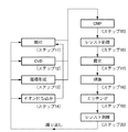
次に上記の露光装置を利用したデバイス製造方法を説明する。図10は、半導体デバイスの全体的な製造プロセスのフローを示す図である。ステップ1(回路設計)では半導体デバイスの回路設計を行う。ステップ2(レチクル作製)では設計した回路パターンに基づいてレチクル(原版またはマスクともいう)を作製する。一方、ステップ3(ウエハ製造)ではシリコン等の材料を用いてウエハ(基板ともいう)を製造する。ステップ4(ウエハプロセス)は前工程と呼ばれ、上記のレチクルとウエハを用いて、リソグラフィー技術によってウエハ上に実際の回路を形成する。次のステップ5(組み立て)は後工程と呼ばれ、ステップ4によって作製されたウエハを用いて半導体チップ化する工程であり、アッセンブリ工程(ダイシング、ボンディング)、パッケージング工程(チップ封入)等の組み立て工程を含む。ステップ6(検査)ではステップ5で作製された半導体デバイスの動作確認テスト、耐久性テスト等の検査を行う。こうした工程を経て半導体デバイスが完成し、これを出荷(ステップ7)する。 図11は、上記ウエハプロセスの詳細なフローを示す図である。ステップ11(酸化)ではウエハの表面を酸化させる。ステップ12(CVD)ではウエハ表面に絶縁膜を成膜する。ステップ13(電極形成)ではウエハ上に電極を蒸着によって形成する。ステップ14(イオン打込み)ではウエハにイオンを打ち込む。ステップ15(CMP)ではCMP工程によって絶縁膜を平坦化する。ステップ16(レジスト処理)ではウエハに感光剤を塗布する。ステップ17(露光)では上記の露光装置を用いて、回路パターンが形成されたマスクを介し感光剤が塗布されたウエハを露光してレジストに潜像パターンを形成する。ステップ18(現像)ではウエハ上のレジストに形成された潜像パターンを現像してレジストパターンを形成する。ステップ19(エッチング)ではレジストパターンが開口した部分を通してレジストパターンの下にある層又は基板をエッチングする。ステップ20(レジスト剥離)ではエッチングが済んで不要となったレジストを取り除く。これらのステップを繰り返し行うことによって、ウエハ上に多重に回路パターンを形成する。
Next, a device manufacturing method using the above exposure apparatus will be described. FIG. 10 is a diagram showing a flow of an entire manufacturing process of a semiconductor device. In step 1 (circuit design), a semiconductor device circuit is designed. In step 2 (reticle fabrication), a reticle (also referred to as an original or a mask) is fabricated based on the designed circuit pattern. On the other hand, in step 3 (wafer manufacture), a wafer (also referred to as a substrate) is manufactured using a material such as silicon. Step 4 (wafer process) is called a pre-process, and an actual circuit is formed on the wafer by lithography using the reticle and wafer. The next step 5 (assembly) is called a post-process, and is a process for forming a semiconductor chip using the wafer produced in
1:光源
2:原版
3:基板
4:シャッタ
5:光センサ
6:投影光学系
7:プリアンプ
9:V/Fコンバータ
11:パルスカウンタ
13:制御部
14:シャッタ駆動回路
15:入出力装置
16:目標露光量決定器
21:原版ステージ
22:基板ステージ
81:シャッタ板
86:光路領域
S:露光量センサ
1: Light source 2: Original plate 3: Substrate 4: Shutter 5: Optical sensor 6: Projection optical system 7: Preamplifier 9: V / F converter 11: Pulse counter 13: Control unit 14: Shutter drive circuit 15: Input / output device 16: Target exposure amount determination unit 21: original stage 22: substrate stage 81: shutter plate 86: optical path region S: exposure amount sensor
Claims (6)
前記原版への前記照明光の入射を制御するための回転シャッタと、
前記照明光の光強度を検出する光センサと、
前記回転シャッタの動作を制御する制御部とを備え、
前記制御部は、第1光強度の照明光を使用して第1基板の複数ショット領域を露光する第1露光モードでは、前記光センサの出力に基づいて前記回転シャッタを閉じるタイミングを制御するとともに、前記回転シャッタの開放時間を記憶し、前記第1光強度よりも強い第2光強度の照明光を使用して前記第1基板に対して後続の第2基板の複数ショット領域を露光する第2露光モードでは、各ショット領域の目標露光量と、前記開放時間に基づいて得られる各ショット領域の補正情報とに基づいて決定される回転速度で前記回転シャッタを回転させ、これによって前記回転シャッタを閉状態から開状態にさせ、更に閉状態にさせる、
ことを特徴とする露光装置。 An exposure apparatus that illuminates an original with illumination light from a light source, projects a pattern of the original onto a substrate by a projection optical system, and exposes the substrate,
A rotating shutter for controlling the incidence of the illumination light on the original plate ;
An optical sensor for detecting the light intensity of the illumination light ;
A control unit for controlling the operation of the rotary shutter,
Wherein the control unit, together with the first exposure mode for exposing a plurality shot region of the first substrate using an illumination light of the first light intensity, controls the timing of closing the rotating shutter on the basis of the output of the optical sensor The opening time of the rotary shutter is stored, and illumination light having a second light intensity higher than the first light intensity is used to expose a plurality of subsequent shot regions of the second substrate with respect to the first substrate . In the two-exposure mode, the rotary shutter is rotated at a rotation speed determined based on the target exposure amount of each shot area and the correction information of each shot area obtained based on the opening time, and thereby the rotary shutter. From the closed state to the open state, and further to the closed state ,
An exposure apparatus characterized by that.
ことを特徴とする請求項1または2に記載の露光装置。 In the second exposure mode , the control unit calculates a correction coefficient based on the exposure amount obtained from the output of the optical sensor and the target exposure amount, and sets the rotation speed of the shutter for the shot area to be exposed. In addition to the correction information, control is performed based on the correction coefficient obtained by exposure of another shot area that has already been exposed.
The exposure apparatus according to claim 1 or 2 , wherein
前記原版への前記照明光の入射を制御するための回転シャッタと、A rotating shutter for controlling the incidence of the illumination light on the original plate;
前記照明光の光強度を検出する光センサと、An optical sensor for detecting the light intensity of the illumination light;
前記回転シャッタの動作を制御する制御部とを備え、A control unit for controlling the operation of the rotary shutter,
前記制御部は、第1光強度の照明光を使用して第1基板の複数ショット領域を露光する第1露光モードでは、前記光センサの出力に基づいて前記回転シャッタを閉じるタイミングを制御するとともに、前記回転シャッタの開放時間を記憶し、前記第1光強度よりも強い第2光強度の照明光を使用して前記第1基板に対して後続の第2基板の複数ショット領域を露光する第2露光モードでは、各ショット領域の目標露光量と、前記開放時間に基づいて得られる各ショット領域の補正情報を含む複数の補正係数とに基づいて決定される回転速度で前記回転シャッタを回転させ、これによって前記回転シャッタを閉状態から開状態にさせ、更に閉状態にさせる、In the first exposure mode in which the illumination light having the first light intensity is used to expose a plurality of shot regions of the first substrate, the control unit controls the timing for closing the rotary shutter based on the output of the photosensor. The opening time of the rotary shutter is stored, and illumination light having a second light intensity higher than the first light intensity is used to expose a plurality of subsequent shot regions of the second substrate with respect to the first substrate. In the two-exposure mode, the rotary shutter is rotated at a rotational speed determined based on a target exposure amount for each shot area and a plurality of correction coefficients including correction information for each shot area obtained based on the release time. In this way, the rotary shutter is changed from the closed state to the open state, and is further closed.
ことを特徴とする露光装置。An exposure apparatus characterized by that.
感光剤が塗布された基板を請求項1乃至5のいずれか1項に記載の露光装置を用いて露光する工程と、A step of exposing a substrate coated with a photosensitive agent using the exposure apparatus according to claim 1;
前記基板を現像する工程と、Developing the substrate;
を含むことを特徴とするデバイス製造方法。A device manufacturing method comprising:
Priority Applications (4)
| Application Number | Priority Date | Filing Date | Title |
|---|---|---|---|
| JP2006302137A JP5100088B2 (en) | 2006-11-07 | 2006-11-07 | Exposure apparatus and device manufacturing method |
| TW096141897A TWI388937B (en) | 2006-11-07 | 2007-11-06 | Exposure apparatus and device manufacturing method |
| US11/935,814 US7936446B2 (en) | 2006-11-07 | 2007-11-06 | Exposure apparatus and device manufacturing method |
| KR1020070112939A KR100972240B1 (en) | 2006-11-07 | 2007-11-07 | Exposure apparatus and device manufacturing method |
Applications Claiming Priority (1)
| Application Number | Priority Date | Filing Date | Title |
|---|---|---|---|
| JP2006302137A JP5100088B2 (en) | 2006-11-07 | 2006-11-07 | Exposure apparatus and device manufacturing method |
Publications (3)
| Publication Number | Publication Date |
|---|---|
| JP2008118062A JP2008118062A (en) | 2008-05-22 |
| JP2008118062A5 JP2008118062A5 (en) | 2009-12-24 |
| JP5100088B2 true JP5100088B2 (en) | 2012-12-19 |
Family
ID=39359445
Family Applications (1)
| Application Number | Title | Priority Date | Filing Date |
|---|---|---|---|
| JP2006302137A Active JP5100088B2 (en) | 2006-11-07 | 2006-11-07 | Exposure apparatus and device manufacturing method |
Country Status (4)
| Country | Link |
|---|---|
| US (1) | US7936446B2 (en) |
| JP (1) | JP5100088B2 (en) |
| KR (1) | KR100972240B1 (en) |
| TW (1) | TWI388937B (en) |
Families Citing this family (7)
| Publication number | Priority date | Publication date | Assignee | Title |
|---|---|---|---|---|
| JP5173650B2 (en) | 2008-07-29 | 2013-04-03 | キヤノン株式会社 | Exposure apparatus and device manufacturing method |
| KR101154779B1 (en) * | 2011-03-11 | 2012-06-18 | 하이디스 테크놀로지 주식회사 | Photolithography method |
| CN103528541B (en) * | 2012-07-04 | 2016-05-04 | 德律科技股份有限公司 | Three-dimension measuring system |
| TWI436030B (en) * | 2012-07-04 | 2014-05-01 | Test Research Inc | Three-dimensional measuring system |
| JP6861463B2 (en) * | 2015-06-16 | 2021-04-21 | キヤノン株式会社 | Exposure equipment and manufacturing method of articles |
| KR102355296B1 (en) * | 2017-08-08 | 2022-01-25 | 삼성전자주식회사 | Semiconductor Memory Device and Apparatus for manufacturing the Same |
| JP7352332B2 (en) * | 2018-05-14 | 2023-09-28 | キヤノン株式会社 | exposure equipment |
Family Cites Families (12)
| Publication number | Priority date | Publication date | Assignee | Title |
|---|---|---|---|---|
| JPS5771132A (en) * | 1980-10-21 | 1982-05-01 | Canon Inc | Exposure controlling system |
| JPS6134252A (en) | 1984-07-20 | 1986-02-18 | 津田駒工業株式会社 | Automatic draw-out method and apparatus of inferior weft yarn in loom |
| JPH0555106A (en) * | 1991-08-28 | 1993-03-05 | Canon Inc | Exposure controller |
| JP2843895B2 (en) * | 1991-10-01 | 1999-01-06 | キヤノン株式会社 | Exposure equipment |
| JP3103461B2 (en) * | 1993-06-29 | 2000-10-30 | キヤノン株式会社 | X-ray exposure method and apparatus, and device manufacturing method |
| JPH06120103A (en) * | 1992-10-07 | 1994-04-28 | Canon Inc | Aligner |
| JPH09320938A (en) * | 1996-05-29 | 1997-12-12 | Nikon Corp | Projection aligner |
| JPH10284371A (en) | 1997-04-03 | 1998-10-23 | Nikon Corp | Exposure method and equipment |
| KR100616293B1 (en) * | 1999-11-11 | 2006-08-28 | 동경 엘렉트론 주식회사 | Substrate processing apparatus and substrate processing method |
| JP2005252161A (en) * | 2004-03-08 | 2005-09-15 | Powerchip Semiconductor Corp | Photolithography system and related method |
| JP5025250B2 (en) * | 2006-12-15 | 2012-09-12 | キヤノン株式会社 | Exposure apparatus and device manufacturing method |
| JP5173650B2 (en) * | 2008-07-29 | 2013-04-03 | キヤノン株式会社 | Exposure apparatus and device manufacturing method |
-
2006
- 2006-11-07 JP JP2006302137A patent/JP5100088B2/en active Active
-
2007
- 2007-11-06 US US11/935,814 patent/US7936446B2/en active Active
- 2007-11-06 TW TW096141897A patent/TWI388937B/en active
- 2007-11-07 KR KR1020070112939A patent/KR100972240B1/en active IP Right Grant
Also Published As
| Publication number | Publication date |
|---|---|
| KR100972240B1 (en) | 2010-07-23 |
| US7936446B2 (en) | 2011-05-03 |
| KR20080041591A (en) | 2008-05-13 |
| TWI388937B (en) | 2013-03-11 |
| JP2008118062A (en) | 2008-05-22 |
| TW200832078A (en) | 2008-08-01 |
| US20080106721A1 (en) | 2008-05-08 |
Similar Documents
| Publication | Publication Date | Title |
|---|---|---|
| JP5100088B2 (en) | Exposure apparatus and device manufacturing method | |
| JP3186011B2 (en) | Projection exposure apparatus and device manufacturing method | |
| US6366341B1 (en) | Exposure method and exposure apparatus | |
| JP5025250B2 (en) | Exposure apparatus and device manufacturing method | |
| JP3254916B2 (en) | Method for detecting coma of projection optical system | |
| US7199878B2 (en) | Scan exposure apparatus and method, and device manufacturing method | |
| JP3376045B2 (en) | Scanning exposure apparatus and device manufacturing method using the scanning exposure apparatus | |
| US7486379B2 (en) | Exposure apparatus, method applied to the apparatus, and device manufacturing method | |
| JP5173650B2 (en) | Exposure apparatus and device manufacturing method | |
| JP4838698B2 (en) | Exposure apparatus and device manufacturing method | |
| JP2008117866A (en) | Exposure device, reticle for exposure device, exposing method and manufacturing method of device | |
| JP2010074043A (en) | Semiconductor manufacturing method and semiconductor manufacturing device | |
| JP4869425B2 (en) | Scanning exposure apparatus and device manufacturing method | |
| JP4277448B2 (en) | Mark detection method and mark detection apparatus | |
| JP2009164355A (en) | Scanning exposure apparatus and method of manufacturing device | |
| JP2009141154A (en) | Scanning exposure apparatus and method of manufacturing device | |
| JP4840958B2 (en) | Scanning exposure apparatus and device manufacturing method | |
| JPH11243050A (en) | Aligner | |
| JP2009016612A (en) | Measuring instrument, exposure apparatus, and device manufacturing method | |
| JP5006711B2 (en) | Exposure apparatus, exposure method, and device manufacturing method | |
| JP2005123234A (en) | Method and device for pattern drawing | |
| JPS63281425A (en) | Transfer device | |
| JP2010199452A (en) | Method of measuring optical characteristic, exposure method, and method of manufacturing device |
Legal Events
| Date | Code | Title | Description |
|---|---|---|---|
| A521 | Written amendment |
Free format text: JAPANESE INTERMEDIATE CODE: A523 Effective date: 20091109 |
|
| A621 | Written request for application examination |
Free format text: JAPANESE INTERMEDIATE CODE: A621 Effective date: 20091109 |
|
| A977 | Report on retrieval |
Free format text: JAPANESE INTERMEDIATE CODE: A971007 Effective date: 20111027 |
|
| A131 | Notification of reasons for refusal |
Free format text: JAPANESE INTERMEDIATE CODE: A131 Effective date: 20111031 |
|
| A521 | Written amendment |
Free format text: JAPANESE INTERMEDIATE CODE: A523 Effective date: 20111228 |
|
| RD03 | Notification of appointment of power of attorney |
Free format text: JAPANESE INTERMEDIATE CODE: A7423 Effective date: 20111228 |
|
| TRDD | Decision of grant or rejection written | ||
| A01 | Written decision to grant a patent or to grant a registration (utility model) |
Free format text: JAPANESE INTERMEDIATE CODE: A01 Effective date: 20120924 |
|
| A01 | Written decision to grant a patent or to grant a registration (utility model) |
Free format text: JAPANESE INTERMEDIATE CODE: A01 |
|
| A61 | First payment of annual fees (during grant procedure) |
Free format text: JAPANESE INTERMEDIATE CODE: A61 Effective date: 20120925 |
|
| FPAY | Renewal fee payment (event date is renewal date of database) |
Free format text: PAYMENT UNTIL: 20151005 Year of fee payment: 3 |
|
| R151 | Written notification of patent or utility model registration |
Ref document number: 5100088 Country of ref document: JP Free format text: JAPANESE INTERMEDIATE CODE: R151 |
|
| FPAY | Renewal fee payment (event date is renewal date of database) |
Free format text: PAYMENT UNTIL: 20151005 Year of fee payment: 3 |