JP6861463B2 - Exposure equipment and manufacturing method of articles - Google Patents
Exposure equipment and manufacturing method of articles Download PDFInfo
- Publication number
- JP6861463B2 JP6861463B2 JP2015121423A JP2015121423A JP6861463B2 JP 6861463 B2 JP6861463 B2 JP 6861463B2 JP 2015121423 A JP2015121423 A JP 2015121423A JP 2015121423 A JP2015121423 A JP 2015121423A JP 6861463 B2 JP6861463 B2 JP 6861463B2
- Authority
- JP
- Japan
- Prior art keywords
- substrate
- illuminance
- exposure
- light
- rotation speed
- Prior art date
- Legal status (The legal status is an assumption and is not a legal conclusion. Google has not performed a legal analysis and makes no representation as to the accuracy of the status listed.)
- Active
Links
Images


Classifications
-
- G—PHYSICS
- G03—PHOTOGRAPHY; CINEMATOGRAPHY; ANALOGOUS TECHNIQUES USING WAVES OTHER THAN OPTICAL WAVES; ELECTROGRAPHY; HOLOGRAPHY
- G03F—PHOTOMECHANICAL PRODUCTION OF TEXTURED OR PATTERNED SURFACES, e.g. FOR PRINTING, FOR PROCESSING OF SEMICONDUCTOR DEVICES; MATERIALS THEREFOR; ORIGINALS THEREFOR; APPARATUS SPECIALLY ADAPTED THEREFOR
- G03F7/00—Photomechanical, e.g. photolithographic, production of textured or patterned surfaces, e.g. printing surfaces; Materials therefor, e.g. comprising photoresists; Apparatus specially adapted therefor
- G03F7/20—Exposure; Apparatus therefor
- G03F7/2002—Exposure; Apparatus therefor with visible light or UV light, through an original having an opaque pattern on a transparent support, e.g. film printing, projection printing; by reflection of visible or UV light from an original such as a printed image
- G03F7/201—Exposure; Apparatus therefor with visible light or UV light, through an original having an opaque pattern on a transparent support, e.g. film printing, projection printing; by reflection of visible or UV light from an original such as a printed image characterised by an oblique exposure; characterised by the use of plural sources; characterised by the rotation of the optical device; characterised by a relative movement of the optical device, the light source, the sensitive system or the mask
-
- G—PHYSICS
- G03—PHOTOGRAPHY; CINEMATOGRAPHY; ANALOGOUS TECHNIQUES USING WAVES OTHER THAN OPTICAL WAVES; ELECTROGRAPHY; HOLOGRAPHY
- G03F—PHOTOMECHANICAL PRODUCTION OF TEXTURED OR PATTERNED SURFACES, e.g. FOR PRINTING, FOR PROCESSING OF SEMICONDUCTOR DEVICES; MATERIALS THEREFOR; ORIGINALS THEREFOR; APPARATUS SPECIALLY ADAPTED THEREFOR
- G03F7/00—Photomechanical, e.g. photolithographic, production of textured or patterned surfaces, e.g. printing surfaces; Materials therefor, e.g. comprising photoresists; Apparatus specially adapted therefor
- G03F7/70—Microphotolithographic exposure; Apparatus therefor
- G03F7/70483—Information management; Active and passive control; Testing; Wafer monitoring, e.g. pattern monitoring
- G03F7/7055—Exposure light control in all parts of the microlithographic apparatus, e.g. pulse length control or light interruption
- G03F7/70558—Dose control, i.e. achievement of a desired dose
-
- G—PHYSICS
- G03—PHOTOGRAPHY; CINEMATOGRAPHY; ANALOGOUS TECHNIQUES USING WAVES OTHER THAN OPTICAL WAVES; ELECTROGRAPHY; HOLOGRAPHY
- G03F—PHOTOMECHANICAL PRODUCTION OF TEXTURED OR PATTERNED SURFACES, e.g. FOR PRINTING, FOR PROCESSING OF SEMICONDUCTOR DEVICES; MATERIALS THEREFOR; ORIGINALS THEREFOR; APPARATUS SPECIALLY ADAPTED THEREFOR
- G03F7/00—Photomechanical, e.g. photolithographic, production of textured or patterned surfaces, e.g. printing surfaces; Materials therefor, e.g. comprising photoresists; Apparatus specially adapted therefor
- G03F7/20—Exposure; Apparatus therefor
- G03F7/2002—Exposure; Apparatus therefor with visible light or UV light, through an original having an opaque pattern on a transparent support, e.g. film printing, projection printing; by reflection of visible or UV light from an original such as a printed image
- G03F7/2004—Exposure; Apparatus therefor with visible light or UV light, through an original having an opaque pattern on a transparent support, e.g. film printing, projection printing; by reflection of visible or UV light from an original such as a printed image characterised by the use of a particular light source, e.g. fluorescent lamps or deep UV light
-
- G—PHYSICS
- G03—PHOTOGRAPHY; CINEMATOGRAPHY; ANALOGOUS TECHNIQUES USING WAVES OTHER THAN OPTICAL WAVES; ELECTROGRAPHY; HOLOGRAPHY
- G03F—PHOTOMECHANICAL PRODUCTION OF TEXTURED OR PATTERNED SURFACES, e.g. FOR PRINTING, FOR PROCESSING OF SEMICONDUCTOR DEVICES; MATERIALS THEREFOR; ORIGINALS THEREFOR; APPARATUS SPECIALLY ADAPTED THEREFOR
- G03F7/00—Photomechanical, e.g. photolithographic, production of textured or patterned surfaces, e.g. printing surfaces; Materials therefor, e.g. comprising photoresists; Apparatus specially adapted therefor
- G03F7/70—Microphotolithographic exposure; Apparatus therefor
- G03F7/70008—Production of exposure light, i.e. light sources
-
- G—PHYSICS
- G03—PHOTOGRAPHY; CINEMATOGRAPHY; ANALOGOUS TECHNIQUES USING WAVES OTHER THAN OPTICAL WAVES; ELECTROGRAPHY; HOLOGRAPHY
- G03F—PHOTOMECHANICAL PRODUCTION OF TEXTURED OR PATTERNED SURFACES, e.g. FOR PRINTING, FOR PROCESSING OF SEMICONDUCTOR DEVICES; MATERIALS THEREFOR; ORIGINALS THEREFOR; APPARATUS SPECIALLY ADAPTED THEREFOR
- G03F7/00—Photomechanical, e.g. photolithographic, production of textured or patterned surfaces, e.g. printing surfaces; Materials therefor, e.g. comprising photoresists; Apparatus specially adapted therefor
- G03F7/70—Microphotolithographic exposure; Apparatus therefor
- G03F7/70216—Mask projection systems
- G03F7/70258—Projection system adjustments, e.g. adjustments during exposure or alignment during assembly of projection system
- G03F7/70266—Adaptive optics, e.g. deformable optical elements for wavefront control, e.g. for aberration adjustment or correction
-
- G—PHYSICS
- G03—PHOTOGRAPHY; CINEMATOGRAPHY; ANALOGOUS TECHNIQUES USING WAVES OTHER THAN OPTICAL WAVES; ELECTROGRAPHY; HOLOGRAPHY
- G03F—PHOTOMECHANICAL PRODUCTION OF TEXTURED OR PATTERNED SURFACES, e.g. FOR PRINTING, FOR PROCESSING OF SEMICONDUCTOR DEVICES; MATERIALS THEREFOR; ORIGINALS THEREFOR; APPARATUS SPECIALLY ADAPTED THEREFOR
- G03F7/00—Photomechanical, e.g. photolithographic, production of textured or patterned surfaces, e.g. printing surfaces; Materials therefor, e.g. comprising photoresists; Apparatus specially adapted therefor
- G03F7/70—Microphotolithographic exposure; Apparatus therefor
- G03F7/70691—Handling of masks or workpieces
- G03F7/70758—Drive means, e.g. actuators, motors for long- or short-stroke modules or fine or coarse driving
Landscapes
- Physics & Mathematics (AREA)
- General Physics & Mathematics (AREA)
- Optics & Photonics (AREA)
- Exposure And Positioning Against Photoresist Photosensitive Materials (AREA)
- Exposure Of Semiconductors, Excluding Electron Or Ion Beam Exposure (AREA)
Description
本発明は、露光装置及び物品の製造方法に関する。 The present invention relates to an exposure apparatus and a method for manufacturing an article.
紫外線ランプを用いたステッパ方式(逐次露光方式)の露光装置では、紫外線ランプからの露光光をON/OFFする機能、即ち、基板への露光光の入射を制御する機能を実現するために、回転シャッタが用いられている。回転シャッタは、光を遮光する遮光部を含む回転体で構成されている。回転シャッタを回転させて、露光光が基板に入射する時間を制御することで目標露光量を得ることができる。 A stepper type (sequential exposure method) exposure device using an ultraviolet lamp rotates in order to realize a function of turning on / off the exposure light from the ultraviolet lamp, that is, a function of controlling the incident of the exposure light on the substrate. A shutter is used. The rotary shutter is composed of a rotating body including a light-shielding portion that blocks light. The target exposure amount can be obtained by rotating the rotary shutter to control the time during which the exposure light is incident on the substrate.
回転シャッタを駆動及び制御するモードとしては、例えば、積算露光制御モードがある。積算露光制御モードでは、まず、露光光を遮光する状態(遮光状態)から露光光を通過させる状態(透光状態)に移行するように回転シャッタを駆動して(回転させて)、かかる透光状態で回転シャッタを停止する。そして、目標露光量に達する前に、透光状態から遮光状態に移行するように回転シャッタを駆動する。この際、回転シャッタの駆動を開始するタイミングは、透光状態から遮光状態に完全に移行するまでに基板に入射する露光光、即ち、露光量を考慮して決定する。積算露光制御モードは、露光量を高精度に制御することが可能であるが、1回の露光処理で回転シャッタの駆動が2回必要となるため、露光処理に要する時間の短縮が課題となる。 As a mode for driving and controlling the rotary shutter, for example, there is an integrated exposure control mode. In the integrated exposure control mode, first, the rotary shutter is driven (rotated) so as to shift from a state in which the exposure light is shielded (light-shielding state) to a state in which the exposure light is passed (transmissive state), and the light is transmitted. Stop the rotary shutter in this state. Then, before reaching the target exposure amount, the rotary shutter is driven so as to shift from the light-transmitting state to the light-shielding state. At this time, the timing at which the rotation shutter is started to be driven is determined in consideration of the exposure light incident on the substrate, that is, the exposure amount until the light transmission state is completely changed to the light blocking state. In the integrated exposure control mode, it is possible to control the exposure amount with high accuracy, but since it is necessary to drive the rotary shutter twice in one exposure process, it is an issue to shorten the time required for the exposure process. ..
そこで、回転シャッタの駆動時間を削減するために、遮光状態から透光状態に移行して再び透光状態に戻るまで、回転シャッタを停止させることなく連続的に駆動するモード、所謂、連続駆動モードが提案されている(特許文献1参照)。連続駆動モードでは、回転シャッタの回転速度と露光量との関係性を予め取得して、実際の露光処理において、かかる関係性に基づいて、目標露光量となるように、回転シャッタの回転速度を制御する。 Therefore, in order to reduce the driving time of the rotary shutter, a mode in which the rotary shutter is continuously driven without stopping until the transition from the light-shielding state to the translucent state and the return to the translucent state is performed, the so-called continuous drive mode. Has been proposed (see Patent Document 1). In the continuous drive mode, the relationship between the rotation speed of the rotary shutter and the exposure amount is acquired in advance, and in the actual exposure process, the rotation speed of the rotary shutter is set so as to reach the target exposure amount based on the relationship. Control.
また、回転シャッタの駆動及び制御に関連する技術として、ロットの1枚目の基板に対しては低速露光モードを実施し、ロットの2枚目以降の基板に対しては高速露光モードを実施する技術が提案されている(特許文献2参照)。低速露光モードでは、基板に入射する露光光の強度を低下させた状態において、光センサの出力に応じたパルス数をカウントし、かかるパルス数が目標パルス数に達した時点で回転シャッタを閉じて、回転シャッタの開放時間を記憶する。一方、高速露光モードでは、まず、低速露光モードで記憶された回転シャッタの開放時間から、2枚目以降の基板の目標露光量を補正して最終目標露光量を算出する。そして、メモリに格納された回転シャッタの回転速度と露光量との関係を示す近似関数又はテーブルに基づいて、最終目標露光量となるように、回転シャッタの回転速度を決定する。 Further, as a technique related to driving and controlling the rotary shutter, a low-speed exposure mode is performed on the first substrate of the lot, and a high-speed exposure mode is implemented on the second and subsequent substrates of the lot. A technique has been proposed (see Patent Document 2). In the low-speed exposure mode, the number of pulses corresponding to the output of the optical sensor is counted in a state where the intensity of the exposure light incident on the substrate is reduced, and when the number of such pulses reaches the target number of pulses, the rotary shutter is closed. , Memorize the opening time of the rotary shutter. On the other hand, in the high-speed exposure mode, first, the final target exposure amount is calculated by correcting the target exposure amount of the second and subsequent substrates from the opening time of the rotary shutter stored in the low-speed exposure mode. Then, the rotation speed of the rotary shutter is determined so as to reach the final target exposure amount based on an approximate function or a table showing the relationship between the rotation speed of the rotary shutter stored in the memory and the exposure amount.
しかしながら、露光光の光源である紫外線ランプは、その使用時間に応じて、得られる照度が徐々に低下していく。従って、特許文献1に開示された連続駆動モードにおいては、紫外線ランプの使用時間に応じて、目標露光量に対する回転シャッタの最適な回転速度が変化することになる。その結果、連続駆動モードでは、回転シャッタによる露光量の精度が徐々に低下して、目標露光量と実際の露光量との間に乖離が生じ、所期の露光結果が得られなくなる。
However, the illuminance obtained by the ultraviolet lamp, which is the light source of the exposure light, gradually decreases according to the usage time. Therefore, in the continuous drive mode disclosed in
このような問題を回避するために、回転シャッタの回転速度と露光量との関係性を定期的なメンテナンスで再度取得して、回転シャッタによる露光量の精度を一定範囲内に維持することが考えられる。但し、近年要求されている露光量の精度を維持するためには、メンテナンスの周期を短くしなければならないため、結果的に、露光装置の稼働率が下がり、生産性を低下させてしまう。 In order to avoid such a problem, it is conceivable to reacquire the relationship between the rotation speed of the rotary shutter and the exposure amount by regular maintenance to maintain the accuracy of the exposure amount by the rotary shutter within a certain range. Be done. However, in order to maintain the accuracy of the exposure amount required in recent years, the maintenance cycle must be shortened, and as a result, the operating rate of the exposure apparatus is lowered and the productivity is lowered.
また、特許文献2に開示された技術においても、紫外線ランプの使用時間、即ち、露光光の照度の低下については何ら考慮されていない。従って、メモリに格納された回転シャッタの回転速度と露光量との関係を示す近似関数又はテーブルを用いて回転シャッタの回転速度を決定したとしても、紫外線ランプの使用時間が多くなるにつれて、最終目標露光量が得られなくなる。
Further, also in the technique disclosed in
本発明は、このような従来技術の課題に鑑みてなされ、基板の露光量の精度と生産性との両立に有利な露光装置を提供することを例示的目的とする。 The present invention has been made in view of such problems of the prior art, and an exemplary object is to provide an exposure apparatus that is advantageous in achieving both accuracy and productivity of the exposure amount of a substrate.
上記目的を達成するために、本発明の一側面としての露光装置は、光源からの光により基板を露光する露光装置であって、前記光を遮光する遮光部を含み、前記基板への前記光の入射を制御するための回転シャッタと、前記回転シャッタの回転速度と、当該回転速度で、前記回転シャッタの回転を停止させずに、前記回転シャッタが前記光を遮光する第1状態から前記回転シャッタが前記光を通過させる第2状態への移行、前記第2状態における前記基板の露光、前記第2状態から前記第1状態への移行の順に行うように、前記回転シャッタを回転させたときの前記基板の露光量との関係を示す第1情報に基づいて、前記基板のショット領域に対する露光処理における前記基板の露光量が目標露光量となるように、前記回転シャッタの回転速度を制御する制御部と、を有し、前記制御部は、前記光の照度が第1照度から第2照度に低下する場合に、前記第1照度から前記第2照度への変化に関する第2情報に基づいて、前記第1情報に含まれる、前記第1照度に対する前記関係を示す第1テーブル又は第1関数を、前記第2照度に対する前記関係を示す第2テーブル又は第2関数になるように、前記第1情報の更新を行い、更新された前記第1情報に基づき前記回転速度を制御することを特徴とする。 In order to achieve the above object, the exposure apparatus as one aspect of the present invention is an exposure apparatus that exposes a substrate by light from a light source, includes a light-shielding portion that blocks the light, and the light to the substrate. The rotation shutter for controlling the incident, the rotation speed of the rotation shutter, and the rotation from the first state in which the rotation shutter blocks the light without stopping the rotation of the rotation shutter at the rotation speed. When the rotary shutter is rotated so as to perform the transition to the second state in which the shutter passes the light, the exposure of the substrate in the second state, and the transition from the second state to the first state. Based on the first information indicating the relationship with the exposure amount of the substrate, the rotation speed of the rotary shutter is controlled so that the exposure amount of the substrate in the exposure process for the shot region of the substrate becomes the target exposure amount. It has a control unit, and the control unit is based on a second information regarding a change from the first illuminance to the second illuminance when the illuminance of the light decreases from the first illuminance to the second illuminance. The first table or first function including the relationship with respect to the first illuminance, which is included in the first information, becomes a second table or second function showing the relationship with respect to the second illuminance. 1 The information is updated, and the rotation speed is controlled based on the updated first information.
本発明の更なる目的又はその他の側面は、以下、添付図面を参照して説明される好ましい実施形態によって明らかにされるであろう。 Further objects or other aspects of the invention will be manifested in the preferred embodiments described below with reference to the accompanying drawings.
本発明によれば、例えば、基板の露光量の精度と生産性との両立に有利な露光装置を提供することができる。 According to the present invention, for example, it is possible to provide an exposure apparatus that is advantageous in achieving both accuracy and productivity of the exposure amount of a substrate.
以下、添付図面を参照して、本発明の好適な実施の形態について説明する。なお、各図において、同一の部材については同一の参照番号を付し、重複する説明は省略する。 Hereinafter, preferred embodiments of the present invention will be described with reference to the accompanying drawings. In addition, in each figure, the same member is given the same reference number, and duplicate description is omitted.
<第1の実施形態>
図1は、本発明の一側面としての露光装置100の構成を示す概略図である。露光装置100は、物品としての半導体素子、液晶表示素子、薄膜磁気ヘッドなどのデバイスの製造に用いられ、基板を露光するリソグラフィ装置である。露光装置100は、本実施形態では、ステッパ方式でレチクル(マスク)のパターンを基板に転写する。
<First Embodiment>
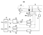
FIG. 1 is a schematic view showing a configuration of an
露光装置100は、光源部LSからの光でレチクル(不図示)を照明する照明光学系ILと、レチクルのパターンを基板に投影する投影光学系(不図示)と、ディテクタ8と、電流ドライバ10と、周波数/電圧変換器11と、電圧/周波数変換器12とを有する。また、露光装置100は、サーボアンプ13と、乗算器14と、ポジションカウンタ15と、露光量カウンタ16と、制御部17とを有する。
The
光源部LSは、基板を露光するための光(露光光)を射出する紫外線ランプ1と、紫外線ランプ1からの光を集光して照明光学系ILに導く楕円ミラー2とを含む。照明光学系ILは、光源部LSからの光でレチクルを照明する時間を制御する、即ち、基板への光の入射を制御するための回転シャッタ3と、レンズ4と、ハーフミラー5と、モータ6と、エンコーダ7とを含む。
The light source unit LS includes an
回転シャッタ3は、例えば、光源部LSからの光を遮光する3つの遮光部301と、光源部LSからの光を通過させる3つの開口部302とを含む回転体で構成されている。モータ6は、回転シャッタ3を回転させるための駆動源である。エンコーダ7は、回転シャッタ3の回転を検出するための検出器である。回転シャッタ3を通過した光は、レンズ4を介して、ハーフミラー5に入射する。ハーフミラー5に入射した光の一部、例えば、ハーフミラー5で反射された光は、光源部LSからの光の照度を検出する検出部や基板の露光量を計測する計測部として機能するディテクタ8に導かれる。また、露光量は、光の照度と時間との積で定義されるものとする。
The
電流ドライバ10は、モータ6に電流を供給してモータ6を駆動する。周波数/電圧変換器(FVC:Frequency Voltage Converter)11は、エンコーダ7から出力される、回転シャッタ3の回転速度に比例したパルス列を電圧に変換する。電圧/周波数変換器(VFC:Voltage Frequency Converter)12は、ディテクタ8から出力される、基板の露光量に比例したアナログ電圧をパルス列に変換する。
The
サーボアンプ13は、回転シャッタ3の実際の回転速度が2次指令値24(によって指示される回転シャッタ3の回転速度)と一致するように、回転シャッタ3の実際の回転速度と2次指令値24との差分に比例する出力を電流ドライバ10に供給する。乗算器14は、回転シャッタ3の回転速度を指示する1次指令値21と、ゲインコントロールデータ20とに基づいて、2次指令値24を生成する。
The
ポジションカウンタ15は、回転シャッタ3の回転位置を監視して位置データ22を出力する。露光量カウンタ16は、VFC12から出力されたパルスを計数することで、ディテクタ8に入射する光の時間的積分量、即ち、基板の露光量を監視して露光量データ23を出力する。
The position counter 15 monitors the rotational position of the
制御部17は、CPU17aやメモリ(記憶部)17bを含み、露光装置100の全体を制御する。例えば、制御部17は、露光装置100の各部を統括的に制御して基板のショット領域を露光する露光処理を行う。制御部17は、回転シャッタ3を連続駆動モードで駆動及び制御する。具体的には、制御部17は、ショット領域に対する露光処理において、遮光部301が光源部LSからの光を遮光する第1状態、開口部302が光源部LSからの光を通過させる第2状態、第1状態の順に移行するように、回転シャッタ3を回転させる。なお、ショット領域を露光している間、制御部17は、回転シャッタ3の回転を停止させない。また、本実施形態では、制御部17は、基板のショット領域に対する露光処理における基板の露光量が目標露光量となるように、回転シャッタ3の回転速度を決定及び制御する。メモリ17bは、回転シャッタ3の回転速度と、かかる回転速度で、回転シャッタ3の回転を停止させずに、第1状態、第2状態、第1状態の順に移行するように、回転シャッタ3を回転させたときの基板の露光量との関係を示す第1情報を記憶する。ここで、第1情報とは、回転シャッタ3の回転速度と基板の露光量との関係を示すテーブル又は関数を含む。
The
図1に示す露光装置100の構成は一例であり、露光装置100の構成を限定するものではない。例えば、露光量は、ディテクタ8から出力されるアナログ電圧をAD変換器に入力し、露光量カウンタ16で算出してもよい。
The configuration of the
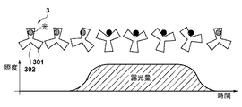
図2は、連続駆動モードにおける回転シャッタ3の駆動状態と基板上の照度との関係を示す図である。ここでは、回転シャッタ3の遮光部301が光源部LSからの光を完全に遮光する状態、即ち、第1状態から回転シャッタ3の回転が開始されるものとする。図3を参照するに、回転シャッタ3の回転が開始されてから直ちに、回転シャッタ3の開口部302が光源部LSからの光を通過させる状態、即ち、第2状態に移行することはなく、回転シャッタ3の回転が開始されてからも第1状態が継続する。
FIG. 2 is a diagram showing the relationship between the driving state of the
光源部LSからの光の端部が遮光部301の端部まで達すると、光が徐々に開口部302を通過し始め、光の逆側の端部が遮光部301の端部まで到達すると、開口部302が光を完全に通過させる状態、即ち、第2状態に移行する。そして、光源部LSからの光の端部が回転シャッタ3の次の遮光部301の端部にかかることで第1状態に移行し始め、光の逆側の端部が次の遮光部301に覆われることで光が完全に遮光され、再び第1状態となる。
When the end of the light from the light source unit LS reaches the end of the light-shielding
図2には、連続駆動モードにおける基板の露光量を示すグラフも示している。かかるグラフでは、基板に入射する光の照度を縦軸に採用し、時間を横軸に採用している。上述したように、基板に入射する光の照度の積分値が基板の露光量となる。連続駆動モードでは、第1状態から第2状態を経て再び第1状態に至る一連の動作を、回転シャッタ3の回転を停止させることなく、回転シャッタ3の1回の駆動で行う。従って、連続駆動モードにおける基板の露光量は、回転シャッタ3の開口部302が光源部LSからの光を通過させている状態での回転シャッタ3の回転速度と、光源部LSからの光の照度とによって決まる。
FIG. 2 also shows a graph showing the exposure amount of the substrate in the continuous drive mode. In such a graph, the illuminance of the light incident on the substrate is adopted on the vertical axis, and the time is adopted on the horizontal axis. As described above, the integrated value of the illuminance of the light incident on the substrate is the exposure amount of the substrate. In the continuous drive mode, a series of operations from the first state to the second state and then to the first state are performed by one drive of the
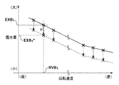
一方、紫外線ランプ1を含む光源部LSからの光の照度は経時的に変化するため、回転シャッタ3の回転速度が同一であるという条件下では、露光量も照度に応じて変化してしまう。そこで、本実施形態では、連続駆動モードにおいて、基板の露光量の精度を維持する(即ち、基板の露光量を正確に制御する)ために、光源部LSからの光の照度に関する第2情報を取得して、回転シャッタ3の駆動にフィードバックする。これにより、基板のショット領域に対する露光処理における基板上の露光量が目標露光量となるように、回転シャッタ3の回転速度を制御することが可能となる。ここで、第2情報とは、後述するように、基板の露光量の経時変化及び光源部LSからの光の照度の経時変化の少なくとも一方を含む。以下、各実施形態において、光源部LSからの光の照度が変化した場合であっても、基板の露光量の精度を維持するための回転シャッタ3の制御について具体的に説明する。
On the other hand, since the illuminance of the light from the light source unit LS including the
<第1の実施形態>
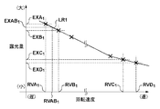
紫外線ランプ1を交換した際には、回転シャッタ3の回転速度に対して基準となる基板の露光量の関係性、即ち、回転シャッタ3の回転速度と、連続駆動モードで回転シャッタ3を回転させたときの基板の露光量との関係を取得する。図3は、回転シャッタ3の回転速度と基板の露光量との関係の一例を示す図である。
<First Embodiment>
When the
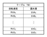
図3を参照するに、回転シャッタ3の回転速度が遅い場合、開口部302が光源部LSからの光を通過させる第2状態にある時間が長くなるため、基板の露光量は大きくなる。そして、回転シャッタ3の回転速度が速くなるにつれて、基板の露光量は小さくなる。例えば、回転シャッタ3を回転速度RVA1で回転させた場合、基板の露光量EXA1がディテクタ8によって計測される。同様に、回転シャッタ3を回転速度RVB1、RVC1及びRVD1のそれぞれで回転させた場合、基板の露光量EXB1、EXC1及びEXD1がディテクタ8によって計測される。このように、本実施形態では、回転シャッタ3の回転速度RVA1、RVB1、RVC1及びRVD1について、それぞれに対応した基板の露光量EXA1、EXB1、EXC1及びEXD1が得られている。図4は、図3に示す回転シャッタ3の回転速度と基板の露光量との関係をテーブル化して得られるテーブル(第1情報)TB1の一例を示す図である。図4に示すテーブルTB1は、例えば、制御部17のメモリ17bに記憶される。
Referring to FIG. 3, when the rotation speed of the
制御部17(CPU17a)は、メモリ17bに記憶されたテーブルTB1に基づいて、ディテクタ8で計測していない回転シャッタ3の回転速度に対応する基板の露光量を、ディテクタ8で計測された基板の露光量を線形補完することで求めることができる。具体的には、図3に示すように、制御部17は、回転速度RVA1に対応する露光量EXA1と、回転速度RVB1に対応する露光量EXB1との間で線形関係式(関数)LR1を決定する。そして、制御部17は、線形関係式LR1から、回転速度RVA1と回転速度RVB1との間における任意の回転速度RVAB1に対応する露光量EXAB1を容易に求めることができる。
Based on the table TB1 stored in the
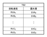
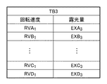
また、メモリ17bには、テーブルTB1に加えて、図5及び図6に示すように、回転シャッタ3の回転速度と基板の露光量との関係が互いに異なる複数のテーブルTB2及びTB3を記憶させる。図3に示すテーブルTB1、図5に示すテーブルTB2及び図6に示すテーブルTB3のそれぞれは、光源部LS(紫外線ランプ1)からの光の照度を変化させることで得ることが可能である。本実施形態では、メモリ17bは、3つのテーブルTB1、TB2及びTB3を記憶しているが、その数を限定するものではなく、2つ以上であればよい。
Further, in the
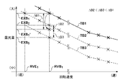
図7を参照して、本実施形態における回転シャッタ3の具体的な制御について説明する。ここでは、図7に示すように、光源部LSからの光の照度の変化に起因して、回転シャッタ3の回転速度RVB1に対応する露光量EXB1が露光量EXB1’に変化した場合を例に説明する。
A specific control of the
制御部17は、メモリ17bに記憶されたテーブルTB1、TB2及びTB3のそれぞれについて、回転速度RVB1に対応する露光量EXB1、EXB2及びEXB3と、露光量EXB1’とを比較し、露光量EXB1’に最も近いテーブルを選択する。図7では、露光量EXB1’と露光量EXB1との差分をΔB1、露光量EXB1’と露光量EXB2との差分をΔB2、露光量EXB1’と露光量EXB3との差分をΔB3で示している。ここで、差分ΔB1、ΔB2及びΔB3の関係がΔB2<ΔB3<ΔB1であるとすると、露光量EXB1’に最も近い露光量は、露光量EXB2となる。
従って、制御部17は、基板のショット領域に対する露光処理における回転シャッタ3の回転速度を決定する際に用いる、回転シャッタ3の回転速度と基板の露光量との関係を示すテーブルを、テーブルTB1からテーブルTB2に更新する。例えば、目標露光量を露光量EXB1とすると、テーブルTB1をテーブルTB2に更新することで、基板のショット領域に対する露光処理における回転シャッタ3の回転速度として、回転速度RVE1が決定(設定)される。このように、光源部LSからの光の照度の変化(第2情報)に応じて、随時、回転シャッタ3の回転速度と基板の露光量との関係を示すテーブルの更新を行うことで、目標露光量に対応する回転シャッタ3の回転速度を決定することができる。そして、制御部17は、基板のショット領域に対する露光処理において、更新したテーブルに基づいて、基板の露光量が目標露光量となるように、回転シャッタ3の回転速度を決定及び制御する。
Therefore, the
露光装置100は、図8に示すように、基板を搬入するロード、基板ステージに保持された基板を位置合わせするアライメント、基板を露光してレチクルのパターンを転写する実露光、露光が完了した基板を搬出するアンロードの順に処理を行う。また、露光装置100は、状況によって、次の露光処理(JOB)が開始されるまで待機する。このように、露光処理は、ロード、アライメント、実露光、アンロード、待機を含み、露光装置100は、基板の各ショット領域に対して、これらの処理を繰り返し行う。
As shown in FIG. 8, the
制御部17は、基板のショット領域を露光する期間を除く期間に、回転シャッタ3の回転速度と基板の露光量との関係を示すテーブルの更新を行う。例えば、制御部17は、ロードの期間に、回転シャッタ3の回転速度と基板の露光量との関係を示すテーブルの更新を行う。具体的には、ロードの期間のうち、投影光学系の下に基板が存在しない期間において、回転シャッタ3を所定の回転速度(第1回転速度)で回転させながら、ディテクタ8によって基板の露光量を計測する。そして、ディテクタ8で計測された露光量、即ち、所定の回転速度に対応する露光量と、メモリ17bに記憶されたテーブルTB1、TB2及びTB3のそれぞれにおける所定の回転速度に対応する露光量とを比較して、テーブルの更新を行う。
The
図8では、基板の露光量のばらつきを考慮して、回転シャッタ3を所定の回転速度で回転させた状態で露光量を3回計測しているが、露光量を計測する回数は1回以上であればよく、その回数を限定するものではない。また、露光装置100がハーフミラー5から基板までの間に遮光機構(不図示)を有する場合には、かかる遮光機構によって光源部LSからの光を遮光することで、投影光学系の下に基板が存在しない期間を確保することができる。
In FIG. 8, the exposure amount is measured three times in a state where the
また、制御部17は、アライメントの期間に、回転シャッタ3の回転速度と基板の露光量との関係を示すテーブルの更新を行ってもよい。アライメントの期間には、回転シャッタ3を開閉する動作を行う、即ち、回転シャッタ3を回転させる場合がある。このような場合、一般的に、実露光時のような高い露光量の精度を要求されることはないため、回転シャッタ3の回転速度を任意に決定することができる。従って、アライメントの期間において、回転シャッタ3を所定の回転速度で回転させた状態で基板の露光量を計測して、回転シャッタ3の回転速度と基板の露光量との関係を示すテーブルの更新を行うことが可能である。
Further, the
また、制御部17は、アンロードの期間においても、ロードの期間と同様に、回転シャッタ3の回転速度と基板の露光量との関係を示すテーブルの更新を行うことが可能である。更に、制御部17は、次の露光処理が開始されるまでの待機の期間においても、回転シャッタ3の回転速度と基板の露光量との関係を示すテーブルの更新を行うことが可能である。
Further, the
ロード、アンロード及び待機のそれぞれの期間では、回転シャッタ3の回転速度を自由に選択可能であり、且つ、投影光学系の下に基板が存在しない期間内で時間の許す限り、基板の露光量の計測が可能であるため、露光量の計測精度を向上させることができる。
In each of the load, unload, and standby periods, the rotation speed of the
また、回転シャッタ3の回転速度と基板の露光量との関係を示すテーブルを更新するために基板の露光量を計測する際には、回転シャッタ3を少なくとも1つの回転速度で回転させればよい。換言すれば、回転シャッタ3に設定する回転速度や回転速度の数を限定するものではない。なお、図8に示すテーブルを更新するタイミングは一例であり、これに限定されるものではない。
Further, when measuring the exposure amount of the substrate in order to update the table showing the relationship between the rotation speed of the
紫外線ランプ1を含む光源部LSからの光の照度の変化は、一般的に、時間的に緩やかである。従って、回転シャッタ3の回転速度と基板の露光量との関係を示すテーブルは、長期的な間隔(例えば、数枚の基板に対して1回など)で更新してもよい。一方、厳密な露光量の精度が求められる場合には、回転シャッタ3の回転速度と基板の露光量との関係を示すテーブルを更新する間隔を可能な限り短くすればよい。回転シャッタ3の回転速度と基板の露光量との関係を示すテーブルを更新するタイミングや間隔などは、制御部17がパラメータとして管理することで、任意のタイミングや間隔を選択することが可能である。
The change in the illuminance of the light from the light source unit LS including the
このように、本実施形態では、回転シャッタ3の回転速度と基板の露光量との関係が互いに異なる複数のテーブルをメモリ17bに記憶させる。そして、光源部LSからの光の照度の変化に基づいて、メモリ17bに記憶された複数のテーブルから1つのテーブルを選択することで、基板のショット領域に対する露光処理における回転シャッタ3の回転速度を決定する際に用いるテーブルの更新を行う。また、ショット領域に対する露光処理における回転シャッタ3の回転速度を決定する前に回転シャッタ3を第1回転速度で回転させながらディテクタ8によって計測された第1露光量と、第1回転速度とに基づいて、1つのテーブルを選択する。この際、例えば、メモリ17bに記憶された複数のテーブルのうち、第1回転速度と第1露光量との関係に最も近い関係を含むテーブルを選択するとよい。
As described above, in the present embodiment, a plurality of tables having different relationships between the rotation speed of the
従って、本実施形態によれば、回転シャッタ3の回転速度と露光量との関係を示すテーブルを再度取得するための定期的なメンテナンスが不要となる。これにより、光源部LSからの光の照度が変化した場合であっても、露光装置100の稼働率を低下させることなく、目標露光量に対応する回転シャッタ3の回転速度を決定することが可能となる。また、本実施形態によれば、光源部LSからの光の照度の変化に応じてテーブルを更新するため、連続駆動モードにおいて、回転シャッタ3による露光量の精度を低下させることなく、一定範囲内に維持することができる。このように、露光装置100は、基板の露光量の精度と生産性との両立を実現することができる。
Therefore, according to the present embodiment, periodic maintenance for reacquiring the table showing the relationship between the rotation speed of the
<第2の実施形態>
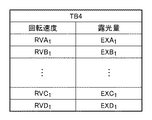
本実施形態では、回転シャッタ3の回転速度と基板の露光量との関係を示す可変テーブルTB4をメモリ17bに記憶させ、光源部LSからの光の照度の変化に応じて、メモリ17bに記憶された可変テーブルTB4における関係を更新する。図9は、回転シャッタ3の回転速度に対して基準となる基板の露光量の関係性、即ち、回転シャッタ3の回転速度と、連続駆動モードで回転シャッタ3を回転させたときの基板の露光量との関係の一例を示す図である。図10は、図9に示す回転シャッタ3の回転速度と基板の露光量との関係をテーブル化して得られる可変テーブルTB4の一例を示す図である。
<Second embodiment>
In the present embodiment, the variable table TB4 showing the relationship between the rotation speed of the
可変テーブルTB4は、上述したように、メモリ17bに記憶される。制御部17は、基板のショット領域に対する露光処理において、メモリ17bに記憶された可変テーブルTB4に基づいて、基板の露光量が目標露光量となるように、回転シャッタ3の回転速度を決定及び制御する。また、上述したように、制御部17は、可変テーブルTB4から得られる回転シャッタ3の回転速度と基板の露光量との線形関係式に基づいて、任意の回転速度に対応する露光量を求めることも可能である。
The variable table TB4 is stored in the
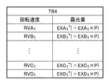
図11及び図12を参照して、本実施形態における回転シャッタ3の具体的な制御について説明する。ここでは、図11に示すように、光源部LSからの光の照度の変化に起因して、回転シャッタ3の回転速度RVB1に対応する露光量EXB1が露光量EXB1’’に変化した場合を例に説明する。図12は、回転シャッタ3の回転速度と基板の露光量との関係が更新された可変テーブルTB4の一例を示す図である。
A specific control of the
制御部17は、図10に示す可変テーブルTB4における回転速度RVB1に対応する露光量EXB1を露光量EXB1’’に更新する。また、その他の回転速度、例えば、回転速度RVA1、RVC1及びRVD1のそれぞれに対応する露光量ついては、露光量EXB1と露光量EXB1’’との変化率(比率)Pを反映させる。具体的には、図10に示す可変テーブルTB4における回転速度RVA1に対応する露光量EXA1に変化率Pを反映させて、露光量EXA1’’(=EXA1×P)に更新する。同様に、図10に示す可変テーブルTB4における回転速度RVC1及びRVD1のそれぞれに対応する露光量EXC1及びEXD1に変化率Pを反映させて、露光量EXC1’’(=EXC1×P)及びEXD1’’(=EXD1×P)に更新する。このように、光源部LSからの光の照度の変化に応じて、随時、可変テーブルTB4における回転シャッタ3の回転速度と基板の露光量との関係の更新を行うことで、目標露光量に対応する回転シャッタ3の回転速度を決定することができる。そして、制御部17は、基板のショット領域に対する露光処理において、更新した可変テーブルTB4に基づいて、基板の露光量が目標露光量となるように、回転シャッタ3の回転速度を決定及び制御する。なお、可変テーブルTB4における回転シャッタ3の回転速度と基板の露光量との関係を更新するタイミングは、第1の実施形態と同様であるため、ここでの詳細な説明は省略する。
The
このように、本実施形態では、回転シャッタ3の回転速度と基板の露光量との関係を更新可能な可変テーブルをメモリ17bに記憶させる。そして、光源部LSからの光の照度の変化に基づいて、基板のショット領域に対する露光処理における回転シャッタ3の回転速度を決定する際に用いる可変テーブルの更新を行う。例えば、ショット領域に対する露光処理における回転シャッタ3の回転速度を決定する前に回転シャッタ3を第1回転速度で回転させながらディテクタ8によって計測された露光量と、更新前の可変テーブルにおける第1回転速度に対応する露光量との変化率を求める。そして、かかる変化率を、可変テーブルにおける回転シャッタ3の回転速度と基板の露光量との関係に反映させることで可変テーブルの更新を行う。
As described above, in the present embodiment, the
従って、本実施形態では、回転シャッタ3の回転速度と基板の露光量との関係を更新可能な可変テーブルを1つ用意すればよいため、第1の実施形態と比較して、テーブルの管理が容易となる。また、光源部LSからの光の照度の変化に起因する基板の露光量の実際の変化を、回転シャッタ3の回転速度と基板の露光量との関係に反映させることができるため、目標露光量に対応する回転シャッタ3の回転速度をより正確に求めることができる。
Therefore, in the present embodiment, it is sufficient to prepare one variable table capable of updating the relationship between the rotation speed of the
<第3の実施形態>
第1の実施形態及び第2の実施形態では、回転シャッタ3の回転速度と基板の露光量との関係を示すテーブルを更新する際に、光源部LSからの光の照度の変化に関する第2情報として、基板の露光量の経時変化を用いている。但し、光源部LSからの光の照度の変化に関する第2情報として、光源部LSからの光の照度の経時変化を用いてもよい。
<Third embodiment>
In the first embodiment and the second embodiment, the second information regarding the change in the illuminance of the light from the light source unit LS when updating the table showing the relationship between the rotation speed of the
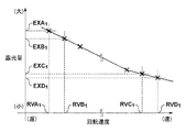
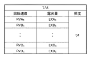
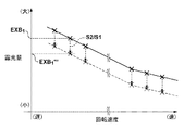
図13は、回転シャッタ3の回転速度に対して基準となる基板の露光量の関係性、即ち、回転シャッタ3の回転速度と、連続駆動モードで回転シャッタ3を回転させたときの基板の露光量との関係の一例を示す図である。図14は、図13に示す回転シャッタ3の回転速度と基板の露光量との関係をテーブル化して得られる可変テーブルTB5の一例を示す図である。可変テーブルTB5は、かかる可変テーブルTBを取得としたときの基準となる光源部LSからの光の照度(第1照度)S1と関連づけられて、メモリ17bに記憶される。制御部17は、基板のショット領域に対する露光処理において、メモリ17bに記憶された可変テーブルTB5に基づいて、基板の露光量が目標露光量となるように、回転シャッタ3の回転速度を決定及び制御する。また、上述したように、制御部17は、可変テーブルTB5から得られる回転シャッタ3の回転速度と基板の露光量との線形関係式に基づいて、任意の回転速度に対応する露光量を求めることも可能である。
FIG. 13 shows the relationship between the rotation speed of the
図15及び図16を参照して、本実施形態における回転シャッタ3の具体的な制御について説明する。ここでは、図15に示すように、光源部LSからの光の照度S1が照度S2に変化した場合を例に説明する。図16は、回転シャッタ3の回転速度と基板の露光量との関係が更新された可変テーブルTB5の一例を示す図である。
Specific control of the
露光装置100において、ディテクタ8は、回転シャッタ3の回転速度にかかわらず、光源部LSからの光の照度を検出することができる。従って、回転シャッタ3の開口部302が光源部LSからの光を通過させる第2状態にある任意のタイミングで光源部LSからの光の照度を検出すればよい。例えば、露光装置100の稼働率の低下を防止するために、第1の実施形態で説明したような基板の露光量を計測するタイミングで照度を検出してもよいし、実露光時に照度を検出してもよい。
In the
制御部17は、図14に示す可変テーブルTB5における露光量EXB1に、照度S1と照度S2との変化率(比率)S2/S1を反映させて、露光量EXB1’’’(=EXB1×S2/S1)に更新する。図14に示す可変テーブルTB5における露光量EXA1、EXC1及びEXD1についても同様である。制御部17は、露光量EXA1、EXC1及びEXD1に変化率S2/S1を反映させて、露光量EXA1’’’(=EXA1×S2/S1)、EXC1’’’(=EXC1×S2/S1)及びEXD1’’’(=EXD1×S2/S1)に更新する。このように、光源部LSからの光の照度の変化に応じて、随時、可変テーブルTB5における回転シャッタ3の回転速度と基板の露光量との関係の更新を行うことで、目標露光量に対応する回転シャッタ3の回転速度を決定することができる。そして、制御部17は、基板のショット領域に対する露光処理において、更新した可変テーブルTB5に基づいて、基板の露光量が目標露光量となるように、回転シャッタ3の回転速度を決定及び制御する。
The
このように、本実施形態では、回転シャッタ3の回転速度と基板の露光量との関係を更新可能な可変テーブルを、そのときの光源部LSからの光の照度(第1照度)に関連づけて、メモリ17bに記憶させる。そして、光源部LSからの光の照度の変化に基づいて、基板のショット領域に対する露光処理における回転シャッタ3の回転速度を決定する際に用いる可変テーブルの更新を行う。例えば、ショット領域に対する露光処理における回転シャッタ3の回転速度を決定する前にディテクタ8によって検出された光源部LSからの光の照度(第2照度)と、更新前の可変テーブルに関連づけられた第1照度との変化率を求める。そして、かかる変化率を、可変テーブルにおける回転シャッタ3の回転速度と基板の露光量との関係に反映させることで可変テーブルの更新を行う。
As described above, in the present embodiment, the variable table capable of updating the relationship between the rotation speed of the
従って、本実施形態では、可変テーブルを更新する際の光源部LSからの光の照度における回転シャッタ3の回転速度と基板の露光量との関係を得ることができる。また、本実施形態では、光源部LSからの光の照度の検出結果を用いているため、回転シャッタ3の回転速度にかかわらず、開口部302が光源部LSからの光を通過させる第2状態にある任意のタイミングで可変テーブルの更新を行うことができる。
Therefore, in the present embodiment, it is possible to obtain the relationship between the rotation speed of the
<第4の実施形態>
第3の実施形態では、ディテクタ8によって検出された光源部LSからの光の照度に基づいて、メモリ17bに記憶された可変テーブルを更新する場合について説明した。但し、紫外線ランプ1を含む光源部LSからの光の照度は、一般的に、その使用時間に応じて低下する傾向がある。
<Fourth Embodiment>
In the third embodiment, the case where the variable table stored in the
図17は、光源部LSの使用時間による照度の経時変化の一例を示す図である。図17では、光源部LSの使用時間を横軸に採用し、光源部LSからの光の照度の維持率を縦軸に採用している。光源部LS、即ち、紫外線ランプ1の種類に応じて、照度の低下の傾向に差異はあるが、光源部LSからの光の現在の照度は、図17に示すように、初期照度及び使用時間から推定することが可能である。
FIG. 17 is a diagram showing an example of a time-dependent change in illuminance due to the usage time of the light source unit LS. In FIG. 17, the usage time of the light source unit LS is adopted on the horizontal axis, and the maintenance rate of the illuminance of the light from the light source unit LS is adopted on the vertical axis. Although there is a difference in the tendency of the illuminance to decrease depending on the type of the light source unit LS, that is, the
そこで、本実施形態では、制御部17は、光源部LSからの光の初期照度と、光源部LSの使用時間とに基づいて、光源部LSからの光の現在の照度を求める。そして、制御部17は、第3の実施形態と同様に、メモリ17bに記憶された可変テーブルにおける露光量に、更新前の可変テーブルに関連づけられた第1照度と現在の照度との変化率(比率)を反映させることで、可変テーブルの更新を行う。
Therefore, in the present embodiment, the
<第5の実施形態>
本発明の実施形態における物品の製造方法は、例えば、デバイス(半導体デバイス、磁気記憶媒体、液晶表示素子など)などの物品を製造するのに好適である。かかる製造方法は、露光装置100を用いて、感光剤が塗布された基板を露光する工程と、露光された基板を現像する工程を含む。また、かかる製造方法は、他の周知の工程(酸化、成膜、蒸着、ドーピング、平坦化、エッチング、レジスト剥離、ダイシング、ボンディング、パッケージングなど)を含みうる。本実施形態における物品の製造方法は、従来に比べて、物品の性能、品質、生産性及び生産コストの少なくとも1つにおいて有利である。
<Fifth Embodiment>
The method for manufacturing an article according to the embodiment of the present invention is suitable for producing an article such as a device (semiconductor device, magnetic storage medium, liquid crystal display element, etc.). Such a manufacturing method includes a step of exposing a substrate coated with a photosensitizer and a step of developing the exposed substrate using an
以上、本発明の好ましい実施形態について説明したが、本発明はこれらの実施形態に限定されないことはいうまでもなく、その要旨の範囲内で種々の変形及び変更が可能である。 Although the preferred embodiments of the present invention have been described above, it goes without saying that the present invention is not limited to these embodiments, and various modifications and modifications can be made within the scope of the gist thereof.
100:露光装置 3:回転シャッタ 301:遮光部 302:開口部 17:制御部 17a:CPU 17b:メモリ
100: Exposure device 3: Rotating shutter 301: Light-shielding part 302: Opening 17:
Claims (10)
前記光を遮光する遮光部を含み、前記基板への前記光の入射を制御するための回転シャッタと、
前記回転シャッタの回転速度と、当該回転速度で、前記回転シャッタの回転を停止させずに、前記回転シャッタが前記光を遮光する第1状態から前記回転シャッタが前記光を通過させる第2状態への移行、前記第2状態における前記基板の露光、前記第2状態から前記第1状態への移行の順に行うように、前記回転シャッタを回転させたときの前記基板の露光量との関係を示す第1情報に基づいて、前記基板のショット領域に対する露光処理における前記基板の露光量が目標露光量となるように、前記回転シャッタの回転速度を制御する制御部と、を有し、
前記制御部は、前記光の照度が第1照度から第2照度に低下する場合に、前記第1照度から前記第2照度への変化に関する第2情報に基づいて、前記第1情報に含まれる、前記第1照度に対する前記関係を示す第1テーブル又は第1関数を、前記第2照度に対する前記関係を示す第2テーブル又は第2関数になるように、前記第1情報の更新を行い、更新された前記第1情報に基づき前記回転速度を制御することを特徴とする露光装置。 An exposure device that exposes a substrate with light from a light source.
A rotary shutter that includes a light-shielding portion that blocks the light and controls the incident of the light on the substrate.
At the rotation speed of the rotary shutter and the rotation speed, from the first state in which the rotary shutter blocks the light to the second state in which the rotary shutter passes the light without stopping the rotation of the rotary shutter. The relationship with the exposure amount of the substrate when the rotary shutter is rotated so as to perform the transition of the above, the exposure of the substrate in the second state, and the transition from the second state to the first state is shown. Based on the first information, it has a control unit that controls the rotation speed of the rotary shutter so that the exposure amount of the substrate in the exposure process for the shot region of the substrate becomes the target exposure amount.
The control unit is included in the first information based on the second information regarding the change from the first illuminance to the second illuminance when the illuminance of the light decreases from the first illuminance to the second illuminance. , The first information is updated and updated so that the first table or the first function showing the relationship with respect to the first illuminance becomes the second table or the second function showing the relationship with respect to the second illuminance. An exposure apparatus characterized in that the rotation speed is controlled based on the first information.
前記制御部は、前記第2情報に基づいて、前記記憶部に記憶された複数の第1情報から1つの第1情報を選択することで前記更新を行うことを特徴とする請求項1に記載の露光装置。 Further having a storage unit for storing a plurality of first pieces of information having different relationships from each other.
The first aspect of claim 1, wherein the control unit performs the update by selecting one first information from a plurality of first information stored in the storage unit based on the second information. Exposure device.
前記制御部は、前記ショット領域に対する露光処理における前記回転シャッタの回転速度を決定する前に前記回転シャッタを第1回転速度で回転させながら前記計測部によって計測された第1露光量と、前記第1回転速度とに基づいて、前記複数の第1情報から前記1つの第1情報を選択することを特徴とする請求項2に記載の露光装置。 Further having a measuring unit for measuring the exposure amount of the substrate,
The control unit has a first exposure amount measured by the measurement unit while rotating the rotation shutter at the first rotation speed before determining the rotation speed of the rotation shutter in the exposure process for the shot region, and the first exposure amount. The exposure apparatus according to claim 2, wherein the one first information is selected from the plurality of first information based on one rotation speed.
前記制御部は、前記ショット領域に対する露光処理における前記回転シャッタの回転速度を決定する前に前記回転シャッタを第1回転速度で回転させながら前記計測部によって計測された露光量と、前記第1情報における前記第1回転速度に対応する前記基板の露光量との変化率を、前記関係に反映させることで前記更新を行うことを特徴とする請求項1に記載の露光装置。 Further having a measuring unit for measuring the exposure amount of the substrate,
The control unit rotates the rotation shutter at the first rotation speed before determining the rotation speed of the rotation shutter in the exposure process for the shot region, and the exposure amount measured by the measurement unit and the first information. The exposure apparatus according to claim 1, wherein the update is performed by reflecting the rate of change with the exposure amount of the substrate corresponding to the first rotation speed in the above relationship.
前記制御部は、前記ショット領域に対する露光処理における前記回転シャッタの回転速度を決定する前に前記検出部によって前記光の照度を検出させることにより前記第1照度及び前記第2照度を求め、前記第2照度と、前記第1照度との変化率を、前記関係に反映させることで前記更新を行うことを特徴とする請求項1に記載の露光装置。 Further having a detection unit for detecting the illuminance of the light,
The control unit obtains the first illuminance and the second illuminance by detecting the illuminance of the light by the detection unit before determining the rotation speed of the rotation shutter in the exposure process for the shot region. The exposure apparatus according to claim 1, wherein the update is performed by reflecting the rate of change between the two illuminances and the first illuminance in the relationship.
前記光の初期照度と、前記光源の使用時間とに基づいて、前記第1照度及び前記第2照度を求め、
前記第2照度と、前記第1照度との変化率を、前記関係に反映させることで前記更新を行うことを特徴とする請求項1に記載の露光装置。 The control unit
Based on the initial illuminance of the light and the usage time of the light source, the first illuminance and the second illuminance are obtained.
The exposure apparatus according to claim 1, wherein the update is performed by reflecting the rate of change between the second illuminance and the first illuminance in the relationship.
露光した前記基板を現像する工程と、
を有し、現像された前記基板から物品を製造することを特徴とする物品の製造方法。 A step of exposing a substrate using the exposure apparatus according to any one of claims 1 to 9.
The process of developing the exposed substrate and
A method for producing an article, which comprises the present invention and comprises producing an article from the developed substrate.
Priority Applications (4)
| Application Number | Priority Date | Filing Date | Title |
|---|---|---|---|
| JP2015121423A JP6861463B2 (en) | 2015-06-16 | 2015-06-16 | Exposure equipment and manufacturing method of articles |
| TW105117380A TWI671601B (en) | 2015-06-16 | 2016-06-02 | Method for exposing substrate with light for light source and method of manufacturing article |
| US15/177,701 US9946164B2 (en) | 2015-06-16 | 2016-06-09 | Exposure apparatus and method of manufacturing article |
| KR1020160074868A KR102080119B1 (en) | 2015-06-16 | 2016-06-16 | Exposure apparatus and method of manufacturing article |
Applications Claiming Priority (1)
| Application Number | Priority Date | Filing Date | Title |
|---|---|---|---|
| JP2015121423A JP6861463B2 (en) | 2015-06-16 | 2015-06-16 | Exposure equipment and manufacturing method of articles |
Publications (3)
| Publication Number | Publication Date |
|---|---|
| JP2017009627A JP2017009627A (en) | 2017-01-12 |
| JP2017009627A5 JP2017009627A5 (en) | 2018-07-12 |
| JP6861463B2 true JP6861463B2 (en) | 2021-04-21 |
Family
ID=57587921
Family Applications (1)
| Application Number | Title | Priority Date | Filing Date |
|---|---|---|---|
| JP2015121423A Active JP6861463B2 (en) | 2015-06-16 | 2015-06-16 | Exposure equipment and manufacturing method of articles |
Country Status (4)
| Country | Link |
|---|---|
| US (1) | US9946164B2 (en) |
| JP (1) | JP6861463B2 (en) |
| KR (1) | KR102080119B1 (en) |
| TW (1) | TWI671601B (en) |
Families Citing this family (3)
| Publication number | Priority date | Publication date | Assignee | Title |
|---|---|---|---|---|
| JP6929142B2 (en) * | 2017-06-19 | 2021-09-01 | キヤノン株式会社 | Exposure equipment and manufacturing method of articles |
| JP7352332B2 (en) * | 2018-05-14 | 2023-09-28 | キヤノン株式会社 | exposure equipment |
| DE102024205430A1 (en) | 2024-06-13 | 2025-12-18 | Carl Zeiss Smt Gmbh | Optomechanical system for projection lithography |
Family Cites Families (10)
| Publication number | Priority date | Publication date | Assignee | Title |
|---|---|---|---|---|
| JPH04229843A (en) | 1990-12-27 | 1992-08-19 | Canon Inc | Shutter for exposing device |
| JP3904034B2 (en) * | 1995-11-17 | 2007-04-11 | 株式会社ニコン | Exposure equipment |
| JPH10247619A (en) * | 1997-03-05 | 1998-09-14 | Nikon Corp | Exposure method and exposure apparatus |
| TWI240852B (en) * | 2004-01-08 | 2005-10-01 | Powerchip Semiconductor Corp | Photolithograph system with variable shutter and method of using the same |
| JP2005252161A (en) * | 2004-03-08 | 2005-09-15 | Powerchip Semiconductor Corp | Photolithography system and related method |
| JP4485282B2 (en) * | 2004-08-06 | 2010-06-16 | シャープ株式会社 | Exposure apparatus, exposure amount control method, exposure amount control program and recording medium therefor |
| JP5100088B2 (en) * | 2006-11-07 | 2012-12-19 | キヤノン株式会社 | Exposure apparatus and device manufacturing method |
| JP5674195B2 (en) * | 2010-01-14 | 2015-02-25 | Nskテクノロジー株式会社 | Exposure apparatus and exposure method |
| JP2013104934A (en) * | 2011-11-11 | 2013-05-30 | Tokyo Electron Ltd | Exposure device and exposure method |
| JP5945211B2 (en) * | 2012-10-26 | 2016-07-05 | 株式会社アルバック | Exposure equipment |
-
2015
- 2015-06-16 JP JP2015121423A patent/JP6861463B2/en active Active
-
2016
- 2016-06-02 TW TW105117380A patent/TWI671601B/en active
- 2016-06-09 US US15/177,701 patent/US9946164B2/en active Active
- 2016-06-16 KR KR1020160074868A patent/KR102080119B1/en active Active
Also Published As
| Publication number | Publication date |
|---|---|
| JP2017009627A (en) | 2017-01-12 |
| TW201715312A (en) | 2017-05-01 |
| US20160370708A1 (en) | 2016-12-22 |
| US9946164B2 (en) | 2018-04-17 |
| KR20160148481A (en) | 2016-12-26 |
| TWI671601B (en) | 2019-09-11 |
| KR102080119B1 (en) | 2020-02-21 |
Similar Documents
| Publication | Publication Date | Title |
|---|---|---|
| TWI600976B (en) | Lithography system and a machine learning controller for such a lithography system | |
| US8717536B2 (en) | Lithographic apparatus, device manufacturing method and associated data processing apparatus and computer program product | |
| US8908148B2 (en) | Calibration method and inspection apparatus | |
| WO1998059364A1 (en) | Projection aligner, method of manufacturing the aligner, method of exposure using the aligner, and method of manufacturing circuit devices by using the aligner | |
| KR101698235B1 (en) | Exposure apparatus and device fabrication method | |
| JP5837693B2 (en) | Lithographic apparatus and device manufacturing method | |
| JP6861463B2 (en) | Exposure equipment and manufacturing method of articles | |
| TW201117259A (en) | An optimization method and a lithographic cell | |
| TW201506349A (en) | A method of measuring overlay error and a device manufacturing method | |
| TWI696884B (en) | Lithographic cluster and method of mitigating overlay drifts or jumps in said lithographic cluster | |
| JP4797046B2 (en) | Lithographic apparatus and lithography system | |
| KR20080015023A (en) | Sensor calibration method, exposure method, exposure apparatus, device manufacturing method, and reflective mask | |
| KR102059034B1 (en) | Method of Transferring Mark Pattern to Substrate, Calibration Method and Lithography Apparatus | |
| TWI620035B (en) | Patterning device cooling system in lithography equipment | |
| JP5405615B2 (en) | Lithographic method and assembly | |
| US8363207B2 (en) | Exposure apparatus, and method of manufacturing device using same | |
| JP2011109014A (en) | Scanning exposure apparatus | |
| US20100248165A1 (en) | Information processing method, exposure processing system using same, device manufacturing method, and information processing apparatus | |
| CN112506007B (en) | Shutter device, light quantity control method, photolithography device and article manufacturing method | |
| KR101497596B1 (en) | Lithographic apparatus and device manufacturing method | |
| US20120147346A1 (en) | Lithographic Apparatus and Method | |
| KR102769082B1 (en) | Exposure apparatus and method of manufacturing article | |
| TWI620031B (en) | Micro-shadow device and method | |
| JP2004153163A (en) | Exposure apparatus control method and apparatus | |
| JP2023049841A (en) | Exposure apparatus, exposure method, and article manufacturing method |
Legal Events
| Date | Code | Title | Description |
|---|---|---|---|
| A521 | Written amendment |
Free format text: JAPANESE INTERMEDIATE CODE: A523 Effective date: 20180528 |
|
| A621 | Written request for application examination |
Free format text: JAPANESE INTERMEDIATE CODE: A621 Effective date: 20180528 |
|
| A131 | Notification of reasons for refusal |
Free format text: JAPANESE INTERMEDIATE CODE: A131 Effective date: 20190322 |
|
| A977 | Report on retrieval |
Free format text: JAPANESE INTERMEDIATE CODE: A971007 Effective date: 20190320 |
|
| A521 | Written amendment |
Free format text: JAPANESE INTERMEDIATE CODE: A523 Effective date: 20190517 |
|
| A02 | Decision of refusal |
Free format text: JAPANESE INTERMEDIATE CODE: A02 Effective date: 20190913 |
|
| A521 | Written amendment |
Free format text: JAPANESE INTERMEDIATE CODE: A523 Effective date: 20191210 |
|
| C60 | Trial request (containing other claim documents, opposition documents) |
Free format text: JAPANESE INTERMEDIATE CODE: C60 Effective date: 20191210 |
|
| A911 | Transfer of reconsideration by examiner before appeal (zenchi) |
Free format text: JAPANESE INTERMEDIATE CODE: A911 Effective date: 20191217 |
|
| C21 | Notice of transfer of a case for reconsideration by examiners before appeal proceedings |
Free format text: JAPANESE INTERMEDIATE CODE: C21 Effective date: 20191220 |
|
| A912 | Removal of reconsideration by examiner before appeal (zenchi) |
Free format text: JAPANESE INTERMEDIATE CODE: A912 Effective date: 20200117 |
|
| C211 | Notice of termination of reconsideration by examiners before appeal proceedings |
Free format text: JAPANESE INTERMEDIATE CODE: C211 Effective date: 20200124 |
|
| C22 | Notice of designation (change) of administrative judge |
Free format text: JAPANESE INTERMEDIATE CODE: C22 Effective date: 20200615 |
|
| C13 | Notice of reasons for refusal |
Free format text: JAPANESE INTERMEDIATE CODE: C13 Effective date: 20201005 |
|
| A521 | Written amendment |
Free format text: JAPANESE INTERMEDIATE CODE: A523 Effective date: 20201127 |
|
| C23 | Notice of termination of proceedings |
Free format text: JAPANESE INTERMEDIATE CODE: C23 Effective date: 20201214 |
|
| RD01 | Notification of change of attorney |
Free format text: JAPANESE INTERMEDIATE CODE: A7421 Effective date: 20210103 |
|
| A521 | Written amendment |
Free format text: JAPANESE INTERMEDIATE CODE: A523 Effective date: 20210113 |
|
| C03 | Trial/appeal decision taken |
Free format text: JAPANESE INTERMEDIATE CODE: C03 Effective date: 20210301 |
|
| C30A | Notification sent |
Free format text: JAPANESE INTERMEDIATE CODE: C3012 Effective date: 20210301 |
|
| A61 | First payment of annual fees (during grant procedure) |
Free format text: JAPANESE INTERMEDIATE CODE: A61 Effective date: 20210330 |
|
| R151 | Written notification of patent or utility model registration |
Ref document number: 6861463 Country of ref document: JP Free format text: JAPANESE INTERMEDIATE CODE: R151 |