JP5098880B2 - Fiber bundle concentrator in spinning machine - Google Patents
Fiber bundle concentrator in spinning machine Download PDFInfo
- Publication number
- JP5098880B2 JP5098880B2 JP2008200813A JP2008200813A JP5098880B2 JP 5098880 B2 JP5098880 B2 JP 5098880B2 JP 2008200813 A JP2008200813 A JP 2008200813A JP 2008200813 A JP2008200813 A JP 2008200813A JP 5098880 B2 JP5098880 B2 JP 5098880B2
- Authority
- JP
- Japan
- Prior art keywords
- fiber bundle
- edge
- downstream
- suction slit
- guide
- Prior art date
- Legal status (The legal status is an assumption and is not a legal conclusion. Google has not performed a legal analysis and makes no representation as to the accuracy of the status listed.)
- Expired - Fee Related
Links
Images


Classifications
-
- D—TEXTILES; PAPER
- D01—NATURAL OR MAN-MADE THREADS OR FIBRES; SPINNING
- D01H—SPINNING OR TWISTING
- D01H5/00—Drafting machines or arrangements ; Threading of roving into drafting machine
- D01H5/18—Drafting machines or arrangements without fallers or like pinned bars
- D01H5/70—Constructional features of drafting elements
- D01H5/72—Fibre-condensing guides
Landscapes
- Engineering & Computer Science (AREA)
- Mechanical Engineering (AREA)
- Textile Engineering (AREA)
- Spinning Or Twisting Of Yarns (AREA)
Abstract
Description
本発明は、紡機における繊維束集束装置に係り、詳しくは例えば精紡機のドラフト装置(ドラフトパート)の下流に配置され、ドラフト装置でドラフトされた繊維束を集束する紡機の繊維束集束装置に関する。 The present invention relates to a fiber bundle concentrating device in a spinning machine, and more particularly to a fiber bundle concentrating device for a spinning machine that is arranged downstream of a draft device (draft part) of a spinning machine and converges the fiber bundle drafted by the draft device.
ドラフトされた繊維束(スライバー)を撚り掛けの前に予め集束し、毛羽の低減等の糸品質の向上を目的とした繊維束集束装置が種々提案され、また実施されている。そして、基本の機能となる繊維束の集束・移送の構成は、吸引スリットを備えた案内面を有する吸引パイプと、その案内面に沿って移動する通気性の(多孔の)搬送ベルトとを備えている(例えば、特許文献1参照。)。 Various fiber bundle converging devices have been proposed and implemented for the purpose of improving the yarn quality such as reducing the fluff by converging the drafted fiber bundle (sliver) in advance before twisting. The fiber bundle converging / transporting structure, which is a basic function, includes a suction pipe having a guide surface with a suction slit, and a breathable (porous) transport belt that moves along the guide surface. (For example, refer to Patent Document 1).
特許文献1に開示された繊維束集束装置は、図6に示すように、ドラフト装置61のフロントローラ対(最終ローラ対)62の繊維束移送方向下流に、吸引パイプ63及びその吸引パイプ63とガイドローラ64とに巻掛けられた多孔の搬送ベルト65を備えている。吸引パイプ63の滑り面には吸引スリット66が設けられている。吸引スリット66の繊維束Fの移動方向下流側端部付近には、繊維束F及び搬送ベルト65を吸引パイプ63に圧着させつつ搬送ベルト65を移動させる締め付けローラ67が設けられている。
As shown in FIG. 6, the fiber bundle concentrating device disclosed in
図7(a)に示すように、吸引スリット66は、搬送ベルト65による繊維束移送方向(矢印方向)に対して傾斜するように形成されている。詳述すると、吸引スリット66は、その幅が繊維束移送方向上流端寄りを除いてほぼ一定に形成され、上流端寄りの部分は上流側に向かって幅広となる形状に形成されている。また、吸引スリット66は、繊維束移動方向上流側を上にして見た場合、幅方向(吸引パイプ63の長手方向)の左側、即ち図7(a),(b)における左側の縁は直線状に形成され、右側の縁は繊維束移動方向上流側寄りの途中から繊維束移送方向と成す角度が大きくなるように屈曲して形成されている。即ち、吸引スリット66は上流端に幅広な開始領域68を有する。そして、吸引スリット66の右側の縁が繊維束Fのガイド縁69を構成している。また、紡機においては、ドラフト装置の繊維束との接触部の偏摩耗を抑制するため、繊維束Fは搬送ベルト65の幅方向に綾振り運動を行いつつ走行するようになっている。そして、特許文献1の装置では、繊維束Fは吸引スリット66の上流端に形成された開始領域68の幅Wの範囲で綾振り運動が行われるようになっている。綾振り幅は5〜6mmと記載されている。
特許文献1の構成では、吸引スリット66の上流端に形成された開始領域68の幅内で繊維束Fの綾振り運動を行わせ、吸引スリット66のガイド縁69に続く開始領域68の下流端縁68aから繊維束Fをガイド縁69に導くようになっている。そのため、開始領域68に進んだ繊維束Fがガイド縁69に沿って移動する距離は、繊維束Fの綾振り運動による開始領域68への進入位置に拘わらず一定になると記載されている。ところが、開始領域68の下流端縁68aの全てを綾振り範囲に対応させようとする場合には、開始領域68の下流端縁68aと搬送ベルト65の繊維束移送方向との成す角度を大きくせざるをえないため、繊維束Fが下流端縁68aのラインに追従せず、繊維束Fがガイド縁69に円滑に導かれないために糸品質のバラツキ要因となる。
In the configuration of
このため、図7(c)に示すように開始領域68の下流端縁68aと搬送ベルト65の繊維束移送方向との成す角度はあまり大きくできず、繊維束Fの綾振り運動の範囲Sは、開始領域68の下流端縁68aと吸引スリット66のガイド縁69との双方に対応する位置に設定せざるを得ない。したがって、吸引スリット66に対する繊維束Fの走行位置が綾振り運動によって変わることによって、繊維束Fが吸引スリット66のガイド縁69に沿って移動する長さが異なる状態になる。具体的には、吸引スリット66に対して左側を走行する繊維束Fは、右側を走行する繊維束Fに比べて、集束に寄与する箇所となるガイド縁69に沿って移動する距離が短くなる。
For this reason, as shown in FIG. 7C, the angle formed by the
これを解決するために、吸引スリット66の繊維束移送方向に対する角度を大きくすると、繊維束Fが吸引スリット66のガイド縁69に追従し難くなる。また、吸引スリット66の全長を長くしてバラツキを小さくすることは、精紡機のレイアウト上難しい。また、吸引スリット66のガイド縁69と反対側の側縁の角度のみを大きくすると、吸引スリット66の幅が狭くなる箇所が発生するため問題がある。
In order to solve this, if the angle of the suction slit 66 with respect to the fiber bundle transfer direction is increased, the fiber bundle F becomes difficult to follow the
本発明は、前記従来の問題に鑑みてなされたものであって、その目的は、紡績糸品質のバラツキを低減することができる紡機における繊維束集束装置を提供することにある。 The present invention has been made in view of the above-described conventional problems, and an object of the present invention is to provide a fiber bundle concentrating device in a spinning machine that can reduce variations in the quality of spun yarn.
前記の目的を達成するため、請求項1に記載の発明は、ドラフト装置の最終送出ローラ対の下流側に設けられ、吸引スリットを備えた案内面を有する吸引パイプと、前記吸引パイプ及びガイド部に巻き掛けられた状態で回転されて繊維束を搬送する通気搬送ベルトとを備えた紡機における繊維束集束装置である。そして、前記吸引スリットは、前記吸引スリットより上流側及び下流側における前記繊維束の走行方向に対して傾斜する状態に形成され、かつ前記吸引スリットの幅方向における両側縁のうちの一方の側縁が前記繊維束を集束するガイド縁を構成するとともに前記ガイド縁は上流部の傾きが下流部の傾きより大きくなるように形成されている。前記ガイド縁と反対側の側縁は、下流部が下流端から前記ガイド縁に沿って延びるように形成され、上流端は、前記ガイド縁と反対側の側縁の下流部を延長した仮想線が前記吸引スリットの前記繊維束の走行方向と直交する上流端縁に沿って延びる仮想線と交差する位置より前記ガイド縁側にずれている。
In order to achieve the above object, the invention according to
ここで、「ガイド縁と反対側の側縁の下流部を延長した仮想線」とは、ガイド縁と反対側の側縁の下流部が直線状の場合は直線の延びる方向に延長した仮想線を意味し、ガイド縁と反対側の側縁の下流部が曲線状の場合は側縁の下流部上端における接線が仮想線を意味する。 Here, “the imaginary line extending the downstream part of the side edge opposite to the guide edge” means the imaginary line extending in the direction of the straight line when the downstream part of the side edge opposite to the guide edge is linear. When the downstream part of the side edge opposite to the guide edge is curved, the tangent at the upper end of the downstream part of the side edge means a virtual line.
この発明では、吸引スリットのガイド縁は上流部の傾きが下流部の傾きより大きく、ガイド縁と反対側の側縁は下流部が下流端から前記ガイド縁に沿って延び、上流端が前記ガイド縁と反対側の側縁の下流部を延長した仮想線が吸引スリットの前記繊維束の走行方向と直交する上流端縁に沿って延びる仮想線と交差する位置よりガイド縁側にずれている。そのため、吸引スリットに対してガイド縁と反対側の側縁よりガイド縁から遠い側から進入する状態で入った繊維束であっても、吸引スリットのガイド縁に沿って移動する距離が上流端を側縁の下流部を延長した仮想線が吸引スリットの前記繊維束の走行方向と直交する上流端縁に沿って延びる仮想線と交差する位置に設定する場合に比べて長くなる。したがって、繊維束の走行位置が異なる場合においてガイド縁に沿って移動する距離の差が小さくなり、紡績糸品質のバラツキを低減することができる。 In the present invention, the guide edge of the suction slit has an inclination of the upstream portion larger than that of the downstream portion, the side edge opposite to the guide edge extends downstream from the downstream end along the guide edge, and the upstream end is the guide edge. An imaginary line extending from the downstream portion of the side edge opposite to the edge is shifted to the guide edge side from a position intersecting with an imaginary line extending along the upstream end edge perpendicular to the traveling direction of the fiber bundle of the suction slit. Therefore, even if the fiber bundle enters in a state of entering from the side farther from the guide edge than the side edge opposite to the guide edge with respect to the suction slit, the distance moved along the guide edge of the suction slit is higher than the upstream end. The imaginary line obtained by extending the downstream portion of the side edge is longer than the case where the imaginary line is set at a position intersecting with the imaginary line extending along the upstream end edge perpendicular to the traveling direction of the fiber bundle of the suction slit. Therefore, when the traveling positions of the fiber bundles are different, the difference in the distance of movement along the guide edge is reduced, and variations in the spun yarn quality can be reduced.
また、請求項1に記載の発明においては、前記ガイド縁と反対側の側縁の上流部は、繊維束引き出し方向に沿う直線部を上流端側に有し、前記反対側の側縁の下流部と前記直線部とは直線又は曲線で接続されている。ガイド縁と反対側の側縁の上流端側に繊維束引き出し方向に沿う直線部が形成されているため、繊維束が上流端よりもガイド縁とは反対側から吸引スリットに導かれる場合に、上流端よりも下流側の吸引スリットの吸引力により繊維束の走行位置が上流端の位置よりもガイド縁と反対方向へずれ、その結果、繊維束が吸引スリットのガイド縁に沿って移動する距離が短くなることが抑制される。したがって、より確実に紡績糸品質のバラツキを低減することができる。 In the first aspect of the present invention , the upstream portion of the side edge opposite to the guide edge has a straight line portion on the upstream end side along the fiber bundle pulling direction, and downstream of the opposite side edge. The part and the straight part are connected by a straight line or a curve . Since the straight portion along the fiber bundle withdrawal direction is formed at the upstream end of the opposite side edges and guide edges, when the fiber bundle is guided from the side opposite to the suction slit and the guide edge of the upstream end The travel position of the fiber bundle is shifted in the direction opposite to the guide edge from the position of the upstream end by the suction force of the suction slit downstream of the upstream end, and as a result, the fiber bundle moves along the guide edge of the suction slit. Shortening of the distance is suppressed. Therefore, it is possible to more reliably reduce the variation in the spun yarn quality.
本発明によれば、紡績糸品質のバラツキを低減することができる紡機における繊維束集束装置を提供することができる。 ADVANTAGE OF THE INVENTION According to this invention, the fiber bundle focusing apparatus in the spinning machine which can reduce the dispersion | variation in spun yarn quality can be provided.
以下、本発明を精紡機に装備される繊維束集束装置に具体化した一実施形態を図1〜図3にしたがって説明する。
図1に示すように、繊維束集束装置11は、ドラフト装置12の最終送出ローラ対13の下流側に設けられている。繊維束集束装置11は送出部14、吸引パイプ15、通気搬送ベルト16及びガイド部17を備えている。送出部14は、最終送出ローラ対13のフロントボトムローラ13aと平行に配設された回転軸18に形成されたニップローラとしてのボトムニップローラ18aと、ボトムニップローラ18aに通気搬送ベルト16を介して押圧されるトップニップローラ19とで構成されている。トップニップローラ19はドラフト装置12のフロントトップローラ13bと同様に2錘毎に、支持部材20を介してウエイティングアーム(図示せず)に支持されている。支持部材20はフロントトップローラ13bの支持部材と一体に形成されている。吸引パイプ15は、送出部14のニップ点に対して繊維束Fの移動方向の上流側に設けられている。
DESCRIPTION OF THE PREFERRED EMBODIMENTS Hereinafter, an embodiment in which the present invention is embodied in a fiber bundle concentrating device installed in a spinning machine will be described with reference to FIGS.
As shown in FIG. 1, the fiber
一方、繊維束集束装置11のボトム側は、ドラフト装置12のローラスタンド21間に配置される錘の半分、この実施形態では4錘分を1ユニットとして構成されている。機台長手方向に所定間隔で配設されたローラスタンド21の中間位置には、機台長手方向に延設された支持ビームに基端側が支持された状態で支持アーム(いずれも図示せず)が配設され、ローラスタンド21と支持アームとの間に回転軸18が支持されている。回転軸18には長手方向の中間部にギヤ22が回転軸18と一体回転可能に設けられている。
On the other hand, the bottom side of the fiber
フロントボトムローラ13aにはギヤ22と対向する位置にギヤ部13cが形成されている。そして、基端側が支持ビームに固定された支持アーム24に中間ギヤ25が回転可能に支持され、中間ギヤ25はギヤ部13c及びギヤ22に噛合している。即ち、フロントボトムローラ13aの回転力は、ギヤ部13c、中間ギヤ25及びギヤ22を介して回転軸18に伝達される。
A
精紡機機台にはその長手方向(図1の紙面と垂直方向)に延びるように吸引ダクト(図示せず)が配設されている。吸引パイプ15は吸引ダクトと平行に延びる状態で、接続管26を介して吸引ダクトに接続されている。吸引パイプ15は、吸引スリット27を備えた案内面28を有する。通気搬送ベルト16は、一部が吸引パイプ15に、一部がガイド部17に、一部がボトムニップローラ18aに接触するように巻き掛けられた状態で回転されて繊維束Fを搬送する。通気搬送ベルト16は、適度な通気性を確保できる織布により形成されている。
The spinning machine base is provided with a suction duct (not shown) so as to extend in the longitudinal direction (perpendicular to the paper surface of FIG. 1). The
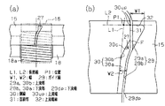
図2(a),(b)に示すように、吸引スリット27は、吸引スリット27より上流側及び下流側における繊維束Fの走行方向(図2(a),(b)の上下方向)に対して傾斜する状態に形成されている。この実施形態では、吸引スリット27は、繊維束移動方向上流側を上にして見た場合、右側に傾斜するように形成されている。吸引スリット27は、吸引スリット27の幅方向(吸引パイプ15の長手方向)における両側縁のうち傾斜方向外側(図2(a),(b)における右側)の側縁が繊維束Fを集束するガイド縁29を構成している。ガイド縁29は、直線状に延びる上流部29a及び下流部29bが連続するように、かつ上流部29aの傾きが下流部29bの傾きより大きくなるように形成されている。なお、上流部29aと下流部29bとの接続部は曲線で滑らかに接続されている。
2 (a) and 2 (b), the suction slit 27 is in the traveling direction of the fiber bundle F on the upstream side and the downstream side of the suction slit 27 (the vertical direction in FIGS. 2 (a) and 2 (b)). It is formed in an inclined state. In this embodiment, the suction slit 27 is formed so as to be inclined to the right when viewed from the upstream side in the fiber bundle moving direction. The suction slit 27 converges the fiber bundle F on the side edge on the outer side in the inclined direction (the right side in FIGS. 2A and 2B) among both side edges in the width direction of the suction slit 27 (longitudinal direction of the suction pipe 15). A
ガイド縁29と反対側の側縁30は、下流部30aが下流端からガイド縁29の下流部29bに沿って延びるように形成されている。この実施形態では、下流部30aはガイド縁29の下流部29bと平行に形成されている。側縁30の上流端30upは、側縁30の下流部30aを延長した仮想線L1が吸引スリット27の上流端縁32に沿って延びる仮想線L2と交差する位置P1よりガイド縁29側にずれている。吸引スリット27の上流端縁32は繊維束Fの走行方向と直交しており、綾振り運動によって繊維束Fの位置が変化しても最終送出ローラ対13のニップ点から吸引スリット27に至る距離が一定に保たれる。
The
側縁30の上流部30bは、繊維束引き出し方向に沿う直線部31を上流端側に有し、側縁30の下流部30aと直線部31とを接続する中間部30cは、下流部30aより傾きが大きくなるように形成された直線で形成されている。直線部31は、その仮想延長線がガイド縁29の上流部29aと交差する位置に形成されている。即ち、側縁30の上流端30upは、上流端30upを通り繊維束Fの走行方向に延びる仮想線がガイド縁29の上流部29aと交差する位置に設けられている。なお、中間部30cの直線は傾きがガイド縁29の上流部29aと同じに形成され、中間部30cの端部は下流部30aに曲線で滑らかに接続されている。
The
吸引スリット27のガイド縁29の上流部29aと下流部29bの長さの比や、側縁30の下流部30aと上流部30bの長さの比、あるいは直線部31の側縁30全体に対する長さの比は、ガイド縁29の傾きとの関係あるいは紡出すべき糸に対する要求品質等によって適宜設定される。
The ratio of the length of the
繊維束Fの綾振り運動の範囲は、側縁30の上流端30upを通り繊維束Fの走行方向に延びる仮想線(図示せず)を含むように設定されている。
次に前記のように構成された装置の作用を説明する。
The range of the traverse movement of the fiber bundle F is set so as to include an imaginary line (not shown) that extends in the traveling direction of the fiber bundle F through the upstream end 30up of the
Next, the operation of the apparatus configured as described above will be described.
精紡機が運転されると、繊維束Fはドラフト装置12でドラフトされた後、最終送出ローラ対13から繊維束集束装置11へ案内される。ボトムニップローラ18a及びトップニップローラ19は最終送出ローラ対13の表面速度と略同等の速度で回転され、繊維束Fは適度な緊張状態で両ローラ18a,19のニップ点を過ぎた後、転向して撚り掛けを受けながら下流側へ移動する。また、繊維束Fは図示しないトラバース装置の作用により綾振り運動を行いながら移動する。なお、この綾振り運動の速度は繊維束Fの進行速度に比べて十分に小さい速度に設定される。
When the spinning machine is operated, the fiber bundle F is drafted by the
また、ダクトの吸引作用が接続管26を介して吸引パイプ15に及び、案内面28に形成された吸引スリット27の吸引作用が通気搬送ベルト16を介して繊維束Fに及ぶ。そして、繊維束Fが吸引スリット27と対応する位置に吸引集束された状態で移動する。したがって、繊維束集束装置11の装備されない紡機に比較して、毛羽の発生や落綿が抑制されて糸質が改善される。
Further, the suction action of the duct extends to the
最終送出ローラ対13から送り出される繊維束Fは綾振り運動により通気搬送ベルト16の搬送方向と直行する方向(吸引スリット27の幅方向)への力を受ける。繊維束Fが吸引スリット27と対応する位置では、繊維束Fは吸引スリット27の吸引作用により通気搬送ベルト16の表面に押圧されるため、繊維束Fが吸引スリット27の幅方向へ移動し難くなる。
The fiber bundle F delivered from the final
本実施形態では、吸引スリット27の側縁30が一直線状ではなく、図2(b)に示すように、側縁30の上流端30upが側縁30の下流部30aを延長した仮想線L1が吸引スリット27の前記繊維束の走行方向と直交する上流端縁32に沿って延びる仮想線L2と交差する位置P1よりガイド縁29側にずれ、かつ直線部31を上流端側に有している。そのため、側縁30の上流端30upよりも図中左側を走行する繊維束Fに対してもガイド縁29の下流部29bにおいて十分な長さで集束を与えることができる。
In the present embodiment, the
したがって、繊維束Fがガイド縁29に沿った状態で集束される領域は、綾振り位置によらずガイド縁29の下端から下流部29bより上流側の範囲となる。その結果、繊維束Fがガイド縁29に押圧され集束される範囲が綾振り位置により大きく異なることが無くなり、紡績糸の品質のバラツキが低減する。
Therefore, the region where the fiber bundle F is converged in a state along the
図2(b)に示す形状の吸引スリット27が形成された吸引パイプ15を使用した場合と、比較例として図7(c)に示す形状の吸引スリット27が形成された吸引パイプ15を使用した場合において、繊維束Fの綾振り運動を行わずに紡出を行った。そして、繊維束Fの走行位置を変更したそれぞれの場合において得られた紡績糸のヘアリネスと糸強力を測定した。結果を図3(a),(b)に示す。紡績糸として綿100%で太さ50番手のものについて試験を行った。なお、ヘアリネスとは毛羽に関する評価項目であり次のように定義される。ヘアリネス:1cmの糸に対する、はみ出し繊維の合計長さ
図3(a)はヘアリネスと繊維束Fの走行位置との関係を示し、図3(b)は糸強力と繊維束Fの走行位置との関係を示すグラフである。図3(a),(b)において走行位置を示す横軸の値「0」は、繊維束Fが吸引スリット27の上流端への進入位置がガイド縁29の下流端29dpと対応する位置を表し、「2」は「0」の位置から右側に2mmずれた位置を表し、「−2」は「0」の位置から左側に2mmずれた位置を表す。また、図3(a)のヘアリネスでは、縦軸において下側に行くほど特性が良くなることを表し、図3(b)の糸強力では、縦軸において上側に行くほど特性が良くなることを表す。図3(a)から、比較例(従来品)の場合に比べて、実施例(発明品)の場合は走行位置の違いによるヘアリネスの変動が小さいことが確認でき、ヘアリネスの評価も良くなっていることが確認できる。また、図3(b)から、比較例(従来品)の場合に比べて、実施例(発明品)の場合は走行位置の違いによる糸強力の変動が小さいことが確認でき、糸強力の評価も良くなっていることが確認できる。
When the
この実施形態によれば、以下に示す効果を得ることができる。
(1)繊維束集束装置11はドラフト装置12の最終送出ローラ対13の下流側に設けられ、吸引スリット27を備えた案内面28を有する吸引パイプ15と、吸引パイプ15及びガイド部17に巻き掛けられた状態で回転されて繊維束Fを搬送する通気搬送ベルト16とを備えている。吸引スリット27は、吸引スリット27より上流側及び下流側における繊維束Fの走行方向に対して傾斜する状態に形成され、かつ吸引スリット27の幅方向における両側縁のうち傾斜方向外側の側縁が繊維束Fを集束するガイド縁29を構成するとともにガイド縁29は上流部29aの傾きが下流部29bの傾きより大きくなるように形成されている。ガイド縁29と反対側の側縁30は、下流部30aが下流端からガイド縁29に沿って延びるように形成され、上流端は、側縁30の下流部30aを延長した仮想線L1が吸引スリット27の前記繊維束の走行方向と直交する上流端縁に沿って延びる仮想線L2と交差する位置よりガイド縁29側にずれている。したがって、繊維束Fがガイド縁29から遠い経路を走行する場合でも、繊維束Fが吸引スリット27のガイド縁29に沿って移動する距離が十分に確保される。その結果、綾振り運動によって繊維束Fの走行位置が異なる場合においてガイド縁29に沿って移動する距離の差が小さくなり、紡績糸品質のバラツキを低減することができる。
According to this embodiment, the following effects can be obtained.
(1) The fiber
(2)吸引スリット27は、ガイド縁29と反対側の側縁30の上流部30bは、繊維束引き出し方向に沿う直線部31を上流端側に有し、反対側の側縁30の下流部30aと直線部31とを接続する中間部30cは、下流部30aより傾きが大きくなるように形成された直線で形成されている。したがって、繊維束Fが上流端30upよりもガイド縁29とは反対側から吸引スリット27に導かれる場合に、上流端30upよりも下流側の吸引スリット27の吸引力により繊維束Fの走行位置が上流端30upの位置よりもガイド縁29と反対方向へずれ、その結果、繊維束Fが吸引スリット27のガイド縁29に沿って移動する距離が短くなることが抑制される。したがって、より確実に紡績糸品質のバラツキを低減することができる。
(2) In the suction slit 27, the
(3)直線部31は、その下端を下流側へ延長した仮想線がガイド縁29の上流部29aと交差する位置に設けられている。したがって、繊維束Fがガイド縁29に押圧されて集束される範囲が長くなり、強紡績糸の品質が向上する。
(3) The
実施形態は前記に限定されるものではなく、例えば、次のように具体化してもよい。
○ 吸引スリット27の形状は、ガイド縁29と反対側の側縁30の上流部30bが、繊維束引き出し方向に沿う直線部31を上流端側に有し、側縁30の下流部30aと直線部31とが中間部30cで接続されたものに限らない。例えば、図4(a)に示すように、繊維束引き出し方向に沿う直線部31を有さず、繊維束引き出し方向と成す角度が下流部30aの成す角度より大きな上流部30bが側縁30の下流部30aに連続して延びる形状としてもよい。この場合、吸引スリット27のガイド縁29と反対側の側縁30の形状が中間部30cを有する場合に比べて単純になる。
The embodiment is not limited to the above, and may be embodied as follows, for example.
The shape of the suction slit 27 is such that the
○ 吸引スリット27は、繊維束移動方向上流側を上にして見た場合、吸引スリット27全体が右側に傾く配置に限らず、例えば、図4(b)に示すように、左側に傾く配置であってもよい。この場合は、吸引スリット27の幅方向の左側の側縁がガイド縁29になるが、繊維束Fの走行位置が異なる場合においてガイド縁29に沿って移動する距離に関しては同様になり、紡績糸品質のバラツキを低減することができる。
○ The suction slit 27 is not limited to the arrangement in which the entire suction slit 27 is inclined to the right side when viewed from the upstream side in the fiber bundle moving direction, but is, for example, an arrangement inclined to the left side as shown in FIG. There may be. In this case, the left side edge in the width direction of the suction slit 27 becomes the
○ 吸引スリット27は、側縁30の下流部30aがガイド縁29と厳密に平行な直線状に延びる形状に限らない。例えば、側縁30の下流部30aとガイド縁29との距離が上流側ほど多少拡がる形状や、側縁30の下流部30a及びガイド縁29の下流部29bが直線状ではなく、下流端から連続的に湾曲する曲線で構成された形状としてもよい。
The suction slit 27 is not limited to a shape in which the
○ 吸引スリット27は、ガイド縁29の上流部29a及び下流部29bの両方が曲線で形成されていてもよい。
○ 繊維束Fを搬送する通気搬送ベルト16を回転させる構成として、図5に示すように、ボトムニップローラ18aより下流側にガイド面33aが円弧面状のガイド部材をガイド部33として設けてもよい。また、吸引パイプ15と吸引ダクトとを接続して吸引パイプ15に負圧を作用させる接続管26をボトムニップローラ18aの前側から吸引パイプ15と接続する位置に配置してもよい。
The suction slit 27 may be formed with a curved portion at both the
As a configuration for rotating the
○ 通気搬送ベルト16を織布や編み地で形成する代わりに、ゴム製や弾性を有する樹脂製のベルトに多数の孔を開けて形成してもよい。
以下の技術的思想(発明)は前記実施形態から把握できる。
O Instead of forming the
The following technical idea (invention) can be understood from the embodiment.
(1)請求項1に記載の発明において、前記吸引スリットのガイド縁と反対側の側縁の下流部を延長した仮想線が前記吸引スリットの上流端の幅方向に延びる仮想線と交差する位置は、前記ガイド縁の下流部上端より前記ガイド縁の上流部上端寄りに設定されている。
(1) In the invention according to
F…繊維束、L1,L2…仮想線、P1…位置、W1,W2…幅、11…繊維束集束装置、12…ドラフト装置、13…最終送出ローラ対、15…吸引パイプ、16…通気搬送ベルト、17,33…ガイド部、27…吸引スリット、28…案内面、29…ガイド縁、29a,30b…上流部、29b,30a…下流部、29dp…下流端、30…側縁、30up…上流端、31…直線部、32…上流端縁。 F ... fiber bundle, L1, L2 ... virtual line, P1 ... position, W1, W2 ... width, 11 ... fiber bundle focusing device, 12 ... draft device, 13 ... final delivery roller pair, 15 ... suction pipe, 16 ... ventilation conveyance Belt, 17, 33 ... guide portion, 27 ... suction slit, 28 ... guide surface, 29 ... guide edge, 29a, 30b ... upstream portion, 29b, 30a ... downstream portion, 29dp ... downstream end, 30 ... side edge, 30up ... Upstream end, 31 ... straight portion, 32 ... upstream end edge.
Claims (1)
前記吸引スリットは、前記吸引スリットより上流側及び下流側における前記繊維束の走行方向に対して傾斜する状態に形成され、かつ前記吸引スリットの幅方向における両側縁のうちの一方の側縁が前記繊維束を集束するガイド縁を構成するとともに前記ガイド縁は上流部の傾きが下流部の傾きより大きくなるように形成され、前記ガイド縁と反対側の側縁は、下流部が下流端から前記ガイド縁に沿って延びるように形成され、上流端は、前記ガイド縁と反対側の側縁の下流部を延長した仮想線が前記吸引スリットの前記繊維束の走行方向と直交する上流端縁に沿って延びる仮想線と交差する位置より前記ガイド縁側にずれており、前記ガイド縁と反対側の側縁の上流部は、繊維束引き出し方向に沿う直線部を上流端側に有し、前記反対側の側縁の下流部と前記直線部とは直線又は曲線で接続されていることを特徴とする紡機における繊維束集束装置。 A suction pipe provided on the downstream side of the final delivery roller pair of the draft device and having a guide surface provided with a suction slit, and an aerial conveyance that conveys the fiber bundle by being rotated around the suction pipe and the guide portion. A fiber bundle focusing device in a spinning machine equipped with a belt,
The suction slit is formed in a state inclined with respect to the traveling direction of the fiber bundle on the upstream side and the downstream side of the suction slit, and one side edge of both side edges in the width direction of the suction slit is the side A guide edge for converging the fiber bundle is formed, and the guide edge is formed such that the inclination of the upstream portion is larger than the inclination of the downstream portion, and the side edge opposite to the guide edge is the downstream portion from the downstream end. An imaginary line extending from the downstream portion of the side edge opposite to the guide edge is formed at an upstream end edge perpendicular to the traveling direction of the fiber bundle of the suction slit. It is shifted to the guide edge side from the position intersecting the virtual line extending along the upstream side of the side edge on the opposite side to the guide edge, and has a straight line portion on the upstream end side along the fiber bundle drawing direction. Side Fiber bundle collecting device for a spinning machine, characterized in that it is connected by a straight line or a curved line downstream portion of the edge and the straight portion.
Priority Applications (4)
| Application Number | Priority Date | Filing Date | Title |
|---|---|---|---|
| JP2008200813A JP5098880B2 (en) | 2008-08-04 | 2008-08-04 | Fiber bundle concentrator in spinning machine |
| EP09166088A EP2151514B1 (en) | 2008-08-04 | 2009-07-22 | Fiber bundle collecting device for spinning machine |
| AT09166088T ATE526440T1 (en) | 2008-08-04 | 2009-07-22 | DEVICE FOR COLLECTING FIBER BUNDLES FOR A SPINNING MACHINE |
| CN2009101618053A CN101643950B (en) | 2008-08-04 | 2009-08-03 | Fiber bundle collecting device for spinning machine |
Applications Claiming Priority (1)
| Application Number | Priority Date | Filing Date | Title |
|---|---|---|---|
| JP2008200813A JP5098880B2 (en) | 2008-08-04 | 2008-08-04 | Fiber bundle concentrator in spinning machine |
Publications (2)
| Publication Number | Publication Date |
|---|---|
| JP2010037677A JP2010037677A (en) | 2010-02-18 |
| JP5098880B2 true JP5098880B2 (en) | 2012-12-12 |
Family
ID=41228422
Family Applications (1)
| Application Number | Title | Priority Date | Filing Date |
|---|---|---|---|
| JP2008200813A Expired - Fee Related JP5098880B2 (en) | 2008-08-04 | 2008-08-04 | Fiber bundle concentrator in spinning machine |
Country Status (4)
| Country | Link |
|---|---|
| EP (1) | EP2151514B1 (en) |
| JP (1) | JP5098880B2 (en) |
| CN (1) | CN101643950B (en) |
| AT (1) | ATE526440T1 (en) |
Families Citing this family (4)
| Publication number | Priority date | Publication date | Assignee | Title |
|---|---|---|---|---|
| JP2012087419A (en) * | 2010-10-15 | 2012-05-10 | Toyota Industries Corp | Fiber bundle-gathering device in spinning machine |
| IT1402834B1 (en) * | 2010-11-10 | 2013-09-27 | Marzoli Spa | COMPACTION DEVICE OF A TAPE OF FIBER TEXTILE IN A FILATOIO |
| CN105586672B (en) * | 2015-12-03 | 2018-04-06 | 江南大学 | A kind of method for reducing the effect of twizzle resistance twist |
| JP7468394B2 (en) * | 2021-02-17 | 2024-04-16 | 株式会社豊田自動織機 | Fiber bundle concentrating device for spinning machine |
Family Cites Families (11)
| Publication number | Priority date | Publication date | Assignee | Title |
|---|---|---|---|---|
| DE3714212A1 (en) * | 1987-04-29 | 1988-11-17 | Fritz Stahlecker | Apparatus for pneumatic false-twist spinning having a drafting unit |
| DE19623824A1 (en) * | 1996-03-06 | 1997-10-09 | Rieter Ag Maschf | Drafting frame for spinning provides two well compacted slivers |
| DE19949666A1 (en) * | 1999-10-14 | 2001-04-19 | Stahlecker Fritz | Sliver compaction by air suction for drafting system includes a tapered suction slot with wider upstream section |
| DE10039732A1 (en) * | 2000-08-15 | 2002-02-28 | Fritz Stahlecker | Condensing stage for drawn sliver, at a sliver drawing unit for a spinner, has a structured fiber guide edge at the suction slit to prevent the sliver twisting in different directions |
| DE10056668A1 (en) * | 2000-11-09 | 2002-05-16 | Fritz Stahlecker | Condensing stage for drawn sliver, at a sliver drawing unit, has a sliding surface for the transport belt formed by an insert into the suction slit of the suction channel, which can be replaced when worn |
| DE10137004A1 (en) * | 2001-07-25 | 2003-02-13 | Stahlecker Gmbh Wilhelm | Spinning machine with a variety of spinning positions |
| DE10321891A1 (en) * | 2003-05-07 | 2004-12-09 | Spindelfabrik Süssen Schurr, Stahlecker & Grill GmbH | Textile ring spinning machine fibre compression station for loose drafted fibres has sickle-shaped slit with funnel inlet to parallel side edges |
| DE102004062796A1 (en) * | 2004-12-20 | 2006-06-29 | Spindelfabrik Süssen Schurr Stahlecker & Grill GmbH | Suction channel for sliver compacting in spinning includes wear-resistant reinforcement strip near suction slot covering several adjacent spinning positions |
| DE102005013765A1 (en) * | 2005-03-22 | 2006-09-28 | Maschinenfabrik Rieter Ag | Method and device for producing coregarn |
| DE102007003525A1 (en) * | 2007-01-19 | 2008-07-31 | Spindelfabrik Suessen Gmbh | Suction channel for stretching unit, has pipe-shaped base plate and suction slot running in peripheral direction of base plate, where suction slot has constant width along fiber routing edge |
| DE102007006282A1 (en) * | 2007-02-01 | 2008-08-07 | Wilhelm Stahlecker Gmbh | Drawframe with compression zone |
-
2008
- 2008-08-04 JP JP2008200813A patent/JP5098880B2/en not_active Expired - Fee Related
-
2009
- 2009-07-22 AT AT09166088T patent/ATE526440T1/en not_active IP Right Cessation
- 2009-07-22 EP EP09166088A patent/EP2151514B1/en active Active
- 2009-08-03 CN CN2009101618053A patent/CN101643950B/en active Active
Also Published As
| Publication number | Publication date |
|---|---|
| JP2010037677A (en) | 2010-02-18 |
| CN101643950B (en) | 2011-10-05 |
| EP2151514A1 (en) | 2010-02-10 |
| ATE526440T1 (en) | 2011-10-15 |
| CN101643950A (en) | 2010-02-10 |
| EP2151514B1 (en) | 2011-09-28 |
Similar Documents
| Publication | Publication Date | Title |
|---|---|---|
| JP3424813B2 (en) | Draft fiber strand bundling device | |
| JP4844336B2 (en) | Fiber bundle concentrator in spinning machine | |
| JP5098880B2 (en) | Fiber bundle concentrator in spinning machine | |
| JP3820951B2 (en) | Fiber bundle focusing device in spinning machine | |
| JP5251855B2 (en) | Fiber bundle concentrator in spinning machine | |
| CN106337257B (en) | Drafting arrangement with a plurality of fiber band guides | |
| JP2012107363A (en) | Draft roller, draft machine and spinning machine | |
| CN107794608B (en) | Fiber bundle bundling device of spinning machine | |
| EP2921577B1 (en) | Draft device and spinning machine | |
| JP3786069B2 (en) | Spinning fiber bundle bundling device | |
| JP2012087419A (en) | Fiber bundle-gathering device in spinning machine | |
| EP2366817B1 (en) | Spinning machine | |
| CN111465728B (en) | Drafting device with collecting mechanism for spinning machine | |
| KR100555188B1 (en) | Fiber bundle collecting device of a spinning machine | |
| JP2021066993A (en) | Convergence device for draft device of spinning machine and draft device of convergence device | |
| JPH0340128B2 (en) | ||
| JP2005023430A (en) | Fiber strand-collecting apparatus | |
| US1799448A (en) | Drawing mechanism for fibrous material | |
| WO2010074138A1 (en) | Gatherer | |
| CN102713035A (en) | Lap winding device for textile machine, for example lap-winder, provided with auxiliary belt | |
| CN203846173U (en) | Improved equipment of compact spinning machine | |
| EP1602755A1 (en) | Drawing device for spinning machine | |
| CN118374910A (en) | Fiber bundle bundling device of textile machine | |
| JPH0510480U (en) | Pneumatic spinning equipment | |
| JPH0551973U (en) | Draft device |
Legal Events
| Date | Code | Title | Description |
|---|---|---|---|
| A621 | Written request for application examination |
Free format text: JAPANESE INTERMEDIATE CODE: A621 Effective date: 20101001 |
|
| A977 | Report on retrieval |
Free format text: JAPANESE INTERMEDIATE CODE: A971007 Effective date: 20120216 |
|
| A131 | Notification of reasons for refusal |
Free format text: JAPANESE INTERMEDIATE CODE: A131 Effective date: 20120221 |
|
| A521 | Request for written amendment filed |
Free format text: JAPANESE INTERMEDIATE CODE: A523 Effective date: 20120406 |
|
| TRDD | Decision of grant or rejection written | ||
| A01 | Written decision to grant a patent or to grant a registration (utility model) |
Free format text: JAPANESE INTERMEDIATE CODE: A01 Effective date: 20120828 |
|
| A01 | Written decision to grant a patent or to grant a registration (utility model) |
Free format text: JAPANESE INTERMEDIATE CODE: A01 |
|
| A61 | First payment of annual fees (during grant procedure) |
Free format text: JAPANESE INTERMEDIATE CODE: A61 Effective date: 20120910 |
|
| FPAY | Renewal fee payment (event date is renewal date of database) |
Free format text: PAYMENT UNTIL: 20151005 Year of fee payment: 3 |
|
| FPAY | Renewal fee payment (event date is renewal date of database) |
Free format text: PAYMENT UNTIL: 20151005 Year of fee payment: 3 |
|
| LAPS | Cancellation because of no payment of annual fees |