JP5096483B2 - Silicide straps in image sensor transfer gate devices - Google Patents
Silicide straps in image sensor transfer gate devices Download PDFInfo
- Publication number
- JP5096483B2 JP5096483B2 JP2009539352A JP2009539352A JP5096483B2 JP 5096483 B2 JP5096483 B2 JP 5096483B2 JP 2009539352 A JP2009539352 A JP 2009539352A JP 2009539352 A JP2009539352 A JP 2009539352A JP 5096483 B2 JP5096483 B2 JP 5096483B2
- Authority
- JP
- Japan
- Prior art keywords
- region
- gate
- transfer gate
- type material
- silicide
- Prior art date
- Legal status (The legal status is an assumption and is not a legal conclusion. Google has not performed a legal analysis and makes no representation as to the accuracy of the status listed.)
- Active
Links
- FVBUAEGBCNSCDD-UHFFFAOYSA-N silicide(4-) Chemical compound [Si-4] FVBUAEGBCNSCDD-UHFFFAOYSA-N 0.000 title claims description 69
- 238000012546 transfer Methods 0.000 title claims description 64
- 229910021332 silicide Inorganic materials 0.000 title description 60
- 239000000463 material Substances 0.000 claims description 52
- 238000000034 method Methods 0.000 claims description 39
- 238000009792 diffusion process Methods 0.000 claims description 34
- 239000000758 substrate Substances 0.000 claims description 25
- 239000004020 conductor Substances 0.000 claims description 18
- 230000009977 dual effect Effects 0.000 claims description 18
- 230000008878 coupling Effects 0.000 claims description 5
- 238000010168 coupling process Methods 0.000 claims description 5
- 238000005859 coupling reaction Methods 0.000 claims description 5
- 239000002800 charge carrier Substances 0.000 claims description 3
- 230000004044 response Effects 0.000 claims description 3
- 239000010410 layer Substances 0.000 description 90
- 229910021420 polycrystalline silicon Inorganic materials 0.000 description 41
- 229920005591 polysilicon Polymers 0.000 description 41
- 239000002019 doping agent Substances 0.000 description 23
- 229910052751 metal Inorganic materials 0.000 description 17
- 239000002184 metal Substances 0.000 description 17
- 238000000151 deposition Methods 0.000 description 15
- 238000005530 etching Methods 0.000 description 12
- 150000004767 nitrides Chemical class 0.000 description 11
- 239000004065 semiconductor Substances 0.000 description 10
- 230000008569 process Effects 0.000 description 9
- XUIMIQQOPSSXEZ-UHFFFAOYSA-N Silicon Chemical compound [Si] XUIMIQQOPSSXEZ-UHFFFAOYSA-N 0.000 description 8
- 238000000137 annealing Methods 0.000 description 8
- 239000007943 implant Substances 0.000 description 8
- 238000005468 ion implantation Methods 0.000 description 8
- 229920002120 photoresistant polymer Polymers 0.000 description 8
- 229910052710 silicon Inorganic materials 0.000 description 8
- 239000010703 silicon Substances 0.000 description 8
- 239000002344 surface layer Substances 0.000 description 7
- 230000004888 barrier function Effects 0.000 description 6
- 238000001020 plasma etching Methods 0.000 description 5
- 125000006850 spacer group Chemical group 0.000 description 5
- ZOXJGFHDIHLPTG-UHFFFAOYSA-N Boron Chemical compound [B] ZOXJGFHDIHLPTG-UHFFFAOYSA-N 0.000 description 4
- OAICVXFJPJFONN-UHFFFAOYSA-N Phosphorus Chemical compound [P] OAICVXFJPJFONN-UHFFFAOYSA-N 0.000 description 4
- 229910052787 antimony Inorganic materials 0.000 description 4
- WATWJIUSRGPENY-UHFFFAOYSA-N antimony atom Chemical compound [Sb] WATWJIUSRGPENY-UHFFFAOYSA-N 0.000 description 4
- 229910052785 arsenic Inorganic materials 0.000 description 4
- RQNWIZPPADIBDY-UHFFFAOYSA-N arsenic atom Chemical compound [As] RQNWIZPPADIBDY-UHFFFAOYSA-N 0.000 description 4
- 229910052796 boron Inorganic materials 0.000 description 4
- 238000011161 development Methods 0.000 description 4
- 238000011065 in-situ storage Methods 0.000 description 4
- 230000036961 partial effect Effects 0.000 description 4
- 229910052698 phosphorus Inorganic materials 0.000 description 4
- 239000011574 phosphorus Substances 0.000 description 4
- 238000000206 photolithography Methods 0.000 description 4
- 239000000654 additive Substances 0.000 description 3
- 230000000996 additive effect Effects 0.000 description 3
- 238000005229 chemical vapour deposition Methods 0.000 description 3
- 230000008021 deposition Effects 0.000 description 3
- 238000001514 detection method Methods 0.000 description 3
- 239000003989 dielectric material Substances 0.000 description 3
- 238000003384 imaging method Methods 0.000 description 3
- 229910052738 indium Inorganic materials 0.000 description 3
- APFVFJFRJDLVQX-UHFFFAOYSA-N indium atom Chemical compound [In] APFVFJFRJDLVQX-UHFFFAOYSA-N 0.000 description 3
- 239000012212 insulator Substances 0.000 description 3
- 150000002500 ions Chemical class 0.000 description 3
- 238000004519 manufacturing process Methods 0.000 description 3
- 229910052759 nickel Inorganic materials 0.000 description 3
- 238000005240 physical vapour deposition Methods 0.000 description 3
- 229910052697 platinum Inorganic materials 0.000 description 3
- IJGRMHOSHXDMSA-UHFFFAOYSA-N Atomic nitrogen Chemical compound N#N IJGRMHOSHXDMSA-UHFFFAOYSA-N 0.000 description 2
- 229910004298 SiO 2 Inorganic materials 0.000 description 2
- 229910000577 Silicon-germanium Inorganic materials 0.000 description 2
- 238000000231 atomic layer deposition Methods 0.000 description 2
- 238000000224 chemical solution deposition Methods 0.000 description 2
- 230000000295 complement effect Effects 0.000 description 2
- 238000001312 dry etching Methods 0.000 description 2
- 238000001704 evaporation Methods 0.000 description 2
- 230000008020 evaporation Effects 0.000 description 2
- 238000002955 isolation Methods 0.000 description 2
- 229910044991 metal oxide Inorganic materials 0.000 description 2
- 150000004706 metal oxides Chemical class 0.000 description 2
- 150000002739 metals Chemical class 0.000 description 2
- 238000012986 modification Methods 0.000 description 2
- 230000004048 modification Effects 0.000 description 2
- 229910052763 palladium Inorganic materials 0.000 description 2
- 238000000623 plasma-assisted chemical vapour deposition Methods 0.000 description 2
- 238000007747 plating Methods 0.000 description 2
- 238000004544 sputter deposition Methods 0.000 description 2
- 238000003860 storage Methods 0.000 description 2
- 229910052715 tantalum Inorganic materials 0.000 description 2
- 229910052719 titanium Inorganic materials 0.000 description 2
- 229910052721 tungsten Inorganic materials 0.000 description 2
- VLJQDHDVZJXNQL-UHFFFAOYSA-N 4-methyl-n-(oxomethylidene)benzenesulfonamide Chemical compound CC1=CC=C(S(=O)(=O)N=C=O)C=C1 VLJQDHDVZJXNQL-UHFFFAOYSA-N 0.000 description 1
- 229910018072 Al 2 O 3 Inorganic materials 0.000 description 1
- 229910019001 CoSi Inorganic materials 0.000 description 1
- GYHNNYVSQQEPJS-UHFFFAOYSA-N Gallium Chemical compound [Ga] GYHNNYVSQQEPJS-UHFFFAOYSA-N 0.000 description 1
- 229910001218 Gallium arsenide Inorganic materials 0.000 description 1
- 229910000673 Indium arsenide Inorganic materials 0.000 description 1
- 229910021193 La 2 O 3 Inorganic materials 0.000 description 1
- FYYHWMGAXLPEAU-UHFFFAOYSA-N Magnesium Chemical compound [Mg] FYYHWMGAXLPEAU-UHFFFAOYSA-N 0.000 description 1
- 229910005883 NiSi Inorganic materials 0.000 description 1
- 229910052581 Si3N4 Inorganic materials 0.000 description 1
- 229910003811 SiGeC Inorganic materials 0.000 description 1
- 229910002367 SrTiO Inorganic materials 0.000 description 1
- 229910010413 TiO 2 Inorganic materials 0.000 description 1
- 229910045601 alloy Inorganic materials 0.000 description 1
- 239000000956 alloy Substances 0.000 description 1
- 229910052790 beryllium Inorganic materials 0.000 description 1
- ATBAMAFKBVZNFJ-UHFFFAOYSA-N beryllium atom Chemical compound [Be] ATBAMAFKBVZNFJ-UHFFFAOYSA-N 0.000 description 1
- 229910001423 beryllium ion Inorganic materials 0.000 description 1
- 230000007547 defect Effects 0.000 description 1
- 238000010586 diagram Methods 0.000 description 1
- 229910052733 gallium Inorganic materials 0.000 description 1
- 239000007789 gas Substances 0.000 description 1
- RPQDHPTXJYYUPQ-UHFFFAOYSA-N indium arsenide Chemical compound [In]#[As] RPQDHPTXJYYUPQ-UHFFFAOYSA-N 0.000 description 1
- 238000002347 injection Methods 0.000 description 1
- 239000007924 injection Substances 0.000 description 1
- 238000010884 ion-beam technique Methods 0.000 description 1
- 238000000608 laser ablation Methods 0.000 description 1
- 238000001459 lithography Methods 0.000 description 1
- 238000004518 low pressure chemical vapour deposition Methods 0.000 description 1
- 229910052749 magnesium Inorganic materials 0.000 description 1
- 239000011777 magnesium Substances 0.000 description 1
- 239000000203 mixture Substances 0.000 description 1
- 229910003465 moissanite Inorganic materials 0.000 description 1
- 229910052750 molybdenum Inorganic materials 0.000 description 1
- 229910052757 nitrogen Inorganic materials 0.000 description 1
- 230000003287 optical effect Effects 0.000 description 1
- 230000003647 oxidation Effects 0.000 description 1
- 238000007254 oxidation reaction Methods 0.000 description 1
- 238000000059 patterning Methods 0.000 description 1
- 229910021340 platinum monosilicide Inorganic materials 0.000 description 1
- 238000012545 processing Methods 0.000 description 1
- 230000005855 radiation Effects 0.000 description 1
- 238000005546 reactive sputtering Methods 0.000 description 1
- 229910010271 silicon carbide Inorganic materials 0.000 description 1
- HQVNEWCFYHHQES-UHFFFAOYSA-N silicon nitride Chemical compound N12[Si]34N5[Si]62N3[Si]51N64 HQVNEWCFYHHQES-UHFFFAOYSA-N 0.000 description 1
- 230000036962 time dependent Effects 0.000 description 1
Images


Classifications
-
- H—ELECTRICITY
- H01—ELECTRIC ELEMENTS
- H01L—SEMICONDUCTOR DEVICES NOT COVERED BY CLASS H10
- H01L27/00—Devices consisting of a plurality of semiconductor or other solid-state components formed in or on a common substrate
- H01L27/14—Devices consisting of a plurality of semiconductor or other solid-state components formed in or on a common substrate including semiconductor components sensitive to infrared radiation, light, electromagnetic radiation of shorter wavelength or corpuscular radiation and specially adapted either for the conversion of the energy of such radiation into electrical energy or for the control of electrical energy by such radiation
- H01L27/144—Devices controlled by radiation
- H01L27/146—Imager structures
- H01L27/14601—Structural or functional details thereof
- H01L27/14609—Pixel-elements with integrated switching, control, storage or amplification elements
-
- H—ELECTRICITY
- H01—ELECTRIC ELEMENTS
- H01L—SEMICONDUCTOR DEVICES NOT COVERED BY CLASS H10
- H01L27/00—Devices consisting of a plurality of semiconductor or other solid-state components formed in or on a common substrate
- H01L27/14—Devices consisting of a plurality of semiconductor or other solid-state components formed in or on a common substrate including semiconductor components sensitive to infrared radiation, light, electromagnetic radiation of shorter wavelength or corpuscular radiation and specially adapted either for the conversion of the energy of such radiation into electrical energy or for the control of electrical energy by such radiation
- H01L27/144—Devices controlled by radiation
- H01L27/146—Imager structures
- H01L27/14643—Photodiode arrays; MOS imagers
-
- H—ELECTRICITY
- H01—ELECTRIC ELEMENTS
- H01L—SEMICONDUCTOR DEVICES NOT COVERED BY CLASS H10
- H01L27/00—Devices consisting of a plurality of semiconductor or other solid-state components formed in or on a common substrate
- H01L27/14—Devices consisting of a plurality of semiconductor or other solid-state components formed in or on a common substrate including semiconductor components sensitive to infrared radiation, light, electromagnetic radiation of shorter wavelength or corpuscular radiation and specially adapted either for the conversion of the energy of such radiation into electrical energy or for the control of electrical energy by such radiation
- H01L27/144—Devices controlled by radiation
- H01L27/146—Imager structures
- H01L27/14683—Processes or apparatus peculiar to the manufacture or treatment of these devices or parts thereof
- H01L27/14689—MOS based technologies
Landscapes
- Physics & Mathematics (AREA)
- Engineering & Computer Science (AREA)
- Power Engineering (AREA)
- Electromagnetism (AREA)
- Condensed Matter Physics & Semiconductors (AREA)
- General Physics & Mathematics (AREA)
- Computer Hardware Design (AREA)
- Microelectronics & Electronic Packaging (AREA)
- Solid State Image Pick-Up Elements (AREA)
- Transforming Light Signals Into Electric Signals (AREA)
Description
本発明は、半導体光学画像センサに関し、特に、低減されたラグ、より高い容量、及びより低い暗電流を示す新規のCMOS(相補型金属酸化膜半導体)画像センサ・セル構造に関する。 The present invention relates to semiconductor optical image sensors, and more particularly to a novel CMOS (complementary metal oxide semiconductor) image sensor cell structure that exhibits reduced lag, higher capacitance, and lower dark current.
CMOS画像センサは、デジタルカメラ、携帯電話機、広範囲なデジタルデバイス、例えばPDA(パーソナル・デジタル・アシスタント)、パーソナル・コンピュータ、医療機器などのような撮像を必要とする用途に対して、コンベンショナルなCCDセンサに取って代わり始めている。CMOS画像センサは、半導体デバイス、例えばフォトダイオードなどのための現行のCMOS製造プロセスを適用することにより、低いコストで製作されるので有利である。さらに、CMOS画像センサは、単一電源によって操作することができるので、そのための消費電力を、CCDセンサよりも低く抑えることができ、そしてさらに、CMOS論理回路及び同様の論理処理デバイスはセンサ・チップ内に容易に集積され、従ってCMOS画像センサを小型化することができる。 CMOS image sensors are conventional CCD sensors for applications that require imaging, such as digital cameras, cell phones, and a wide range of digital devices such as PDAs (Personal Digital Assistants), personal computers, medical equipment, etc. Has begun to replace. CMOS image sensors are advantageous because they are manufactured at low cost by applying current CMOS manufacturing processes for semiconductor devices such as photodiodes. Furthermore, since the CMOS image sensor can be operated by a single power supply, the power consumption for it can be kept lower than that of a CCD sensor, and moreover, CMOS logic circuits and similar logic processing devices are sensor chips. Therefore, the CMOS image sensor can be miniaturized.
現在のCMOS画像センサは、CMOSアクティブピクセルセンサ(Active Pixel Sen sor (APS))セル・アレイを含んでおり、これらのセルは、光エネルギーを捕集し、そしてこれを読み取り可能な電気信号に変換するために使用される。各APSセルは、光生成電荷を下側部分に蓄積するための基板のドープされた領域の上に位置する感光性素子、例えばフォトダイオード、フォトゲート、又は光伝導体を含む。各ピクセルセルには読み取り回路が接続されており、この回路はしばしば、読み取り時に感光性素子からの電荷を受容するための拡散領域を含む。典型的には、このことは、浮動拡散領域に電気的に接続されたゲートを有するトランジスタデバイスによって達成される。撮像素子は、感光性素子からチャネルを横切って浮動拡散領域へ電荷を移動するための、トランスファゲートを有するトランジスタと、電荷移動前に浮動拡散領域を所定の電荷レベルにリセットするためのトランジスタとを含んでいてもよい。 Current CMOS image sensors include a CMOS Active Pixel Sensor (APS) cell array that collects light energy and converts it into readable electrical signals. Used to do. Each APS cell includes a photosensitive element, such as a photodiode, photogate, or photoconductor, overlying a doped region of the substrate for storing photogenerated charge in the lower portion. Each pixel cell is connected to a reading circuit, which often includes a diffusion region for accepting charge from the photosensitive element during reading. Typically this is accomplished by a transistor device having a gate electrically connected to the floating diffusion region. The imaging device includes a transistor having a transfer gate for transferring charge from the photosensitive element across the channel to the floating diffusion region, and a transistor for resetting the floating diffusion region to a predetermined charge level before the charge transfer. May be included.
図1に示されているように、典型的なCMOS APSセル10は、ドープp型ピニング層18と、下側の軽度ドープn型領域17とを有するピンド・フォトダイオード20を含む。典型的には、ピンド・ダイオード20は、ダイオード・ピニング層18よりもp型濃度が低いp型基板15又はp型エピタキシャル層又はpウェル表面層の最上部に形成されている。図から明らかなように、表面ドープp型ピニング層18は基板15(又はp型エピタキシャル層又はpウェル表面層)と電気的に接触している。フォトダイオード20はこうして、n型ドープ領域17がピニング電圧(Vp)で完全消耗するように、同じ電位を有する2つのp型領域18及び15を備えている。すなわち、表面ピニング層18は、基板と電気的な接触状態になる。ピンド・フォトダイオードは、フォトダイオードが完全消耗した時にフォトダイオード中の電位が一定の値Vpにピン固定されるので「ピンド(pinned)」と呼ばれる。このピンド・フォトダイオードの形態は、暗電流(暗環境においてピクセルによって出力される電流)を減少させることにより、デバイス性能を改善する。しかし、ピンド・フォトダイオードの形態は、フォトダイオードから浮動ノードへの電荷の不完全な移動による画像ラグを招くおそれがある。
As shown in FIG. 1, a typical
図1にさらに示されているように、フォトダイオード20のn型ドープ領域17及びp領域18は、絶縁領域、すなわちシャロートレンチ分離(STI)領域40と、薄型スペーサ構造23a,bによって取り囲まれた電荷移動トランジスタ・ゲート25との間に、所定の間隔を置いて設けられている。シャロートレンチ分離(STI)領域40は、セルを隣接ピクセルセルから分離するために、ピクセル画像セルの近くに配置されている。動作中、ピクセルから来た光は、ダイオードを通ってフォトダイオード上に集束され、ここで、電子がn型領域17に集まる。トランスファゲート25が操作されると、すなわち、例えば薄型誘電体層60上のn型ドープ・ポリシリコン層70を含むトランスファゲート70に電圧を印加することによりオンにされると、光生成電荷24は、電荷を蓄積するドープn型領域17から、トランスファデバイス・チャネル16を介して、浮動拡散領域30、例えば浮動「ノード」ドープn+型に移動される。
As further shown in FIG. 1, the n-type doped
図2はさらに、p型材料部分70aと、n型部分70bとを有するゲート25’が内蔵された別の従来技術CMOS APSセル10’を示している。ゲートのn型部分70bは、より低いVtを有しており、ゲートのp型部分70aはより高いVtを有している。同時にゲート内に存在する両方を有することにより、トランスファゲートは、フォトダイオードから浮動拡散領域へ電子を引き付ける、組み込まれた場を有する。加えて、CMOS APSセル10’の構成において、アレイ内で浮動ノード拡散領域上に形成されたシリサイド(silicide)コンタクト領域(図示せず)の存在が、輝点欠陥漏れの問題を引き起こすことが示されている。すなわち、これらの拡散領域上に形成されたシリサイドコンタクトの追加の存在によって、偶発的なピクセルが、そのピクセルを使用不能にするのに十分な高さのレベルで電流を漏らすシリサイド「スパイク」を被ることが判っている。その結果として、シリサイドは、輝点収率のために、CMOS撮像素子のアレイから除去されている。
FIG. 2 further shows another prior art CMOS APS cell 10 'incorporating a gate 25' having a p-
図3Aはシリサイドが光を遮断するため、シリサイド層をフォトダイオード表面から遮断された状態で有するCMOS撮像素子12を示しているが、トランスファゲートポリシリコン及び浮動拡散領域上に形成されたシリサイド層80はそのまま残っている。図3Bは、図3AのCMOS撮像素子12を、漏れ挙動をさらに低くするために、シリサイド層80をゲートポリ及び浮動拡散領域から除去した状態で示している。
FIG. 3A shows the
図3Cは、図2のCMOS撮像素子10’を、シリサイド表面層をフォトダイオード20、ゲートポリ領域70a,70b及び浮動拡散ノード30から除去した状態で示す頂面図である。
3C is a top view showing the
しかし、残念ながら、n領域及びp領域を有するトランスファゲートを備えた撮像素子からシリサイドを除去すると、ゲート内部の内蔵型ダイオードを有するように形成された各CMOS APSセル・ゲート・ポリシリコンは、ゲート全体がコンタクト形成されるのを妨げる。すなわち、ポリシリコンゲートのn型又はp型にだけ接続するコンタクトは、ゲートポリ層の他方の極性に十分に接続されることはない。このことは、ゲートのコンタクト形成されていない部分に時間依存性の電圧をもたらす。すなわち、ゲートのn型部分に対するコンタクトが形成されると、p型部分が浮動し、同様に、ゲートのp型部分に対するコンタクトが形成されると、n型部分が浮動する。コンタクトが境界エッジ上に直接形成されると、コンタクト・オーバーレイは、コンタクトが統計的に見て一方の側だけに接触することしか許さない。 Unfortunately, however, when silicide is removed from an imaging device having a transfer gate having an n region and a p region, each CMOS APS cell gate polysilicon formed to have a built-in diode inside the gate becomes a gate. Prevents the whole from being contacted. That is, contacts that connect only to the n-type or p-type of the polysilicon gate are not fully connected to the other polarity of the gate poly layer. This results in a time dependent voltage on the uncontacted part of the gate. That is, when a contact to the n-type portion of the gate is formed, the p-type portion floats. Similarly, when a contact to the p-type portion of the gate is formed, the n-type portion floats. When a contact is formed directly on the boundary edge, the contact overlay only allows the contact to contact only one side as viewed statistically.
従って、低減された(低)ラグ及び暗電流を示す新規のAPSセル構造、並びに輝点スパイク漏れ現象を排除する新規のAPSセル構造を含む、CMOS画像センサ・セル構造を提供することが強く望まれる。 Accordingly, it would be highly desirable to provide a CMOS image sensor cell structure that includes a novel APS cell structure that exhibits reduced (low) lag and dark current, and a novel APS cell structure that eliminates the bright spot spike leakage phenomenon. It is.
本発明は概ね、改善された半導体撮像素子に関し、そして具体的には、標準的なCMOS法を用いて製造することができる撮像素子に関する。 The present invention generally relates to an improved semiconductor image sensor, and in particular to an image sensor that can be manufactured using standard CMOS methods.
本発明は、CMOS画像センサであって、センサが、光検出領域(例えばフォトダイオード);浮動拡散領域;光検出領域と浮動拡散領域との間に配置されたトランスファゲート、該トランスファゲートはダイオードを形成するためにn型ドープ領域とp型ドープ領域とを含む;トランスファゲートのn型ドープ領域とp型ドープ領域と電気的にカップリングする相互接続層(例えばシリサイド構造)を含んで成るCMOS画像センサに関する。 The present invention relates to a CMOS image sensor, wherein the sensor is a light detection region (eg, a photodiode); a floating diffusion region; a transfer gate disposed between the light detection region and the floating diffusion region, the transfer gate including a diode. CMOS image comprising an n-type doped region and a p-type doped region to form; an interconnect layer (eg, a silicide structure) electrically coupled to the n-type doped region and the p-type doped region of the transfer gate It relates to sensors.
本発明の1つの態様の場合、相互接続層はシリサイドを含む、ポリシリコントランスファゲートのp型領域の少なくとも一部と、n型領域の少なくとも一部と物理的に接触状態にあるように形成されている。シリサイド層は、ポリゲート幅全体にわたって又はその一部だけに形成されていてよく、またシリサイドは、拡散領域(すなわちフォトダイオード及び浮動拡散領域)上には形成されない。 In one aspect of the invention, the interconnect layer is formed to be in physical contact with at least a portion of the p-type region of the polysilicon transfer gate and at least a portion of the n-type region, including silicide. ing. The silicide layer may be formed over the entire polygate width or only part of it, and no silicide is formed over the diffusion regions (ie, photodiodes and floating diffusion regions).
好ましくは、2つの仕事関数(n型及びp型ゲートポリ)を有するトランスファゲートデバイスとシリサイドストラップとを含む本発明のCMOS撮像素子は協働して、暗電流に対しては、フォトダイオードに高いバリアを示すのに対して、低いラグ・パフォーマンスに対しては浮動拡散領域に低いバリアが提供される。シリサイドストラップは、ダイオード挙動が、ゲートの一方又は他方の側が不確定電圧に浮動するのを許すのを防止する。 Preferably, the CMOS imager of the present invention comprising a transfer gate device having two work functions (n-type and p-type gate poly) and a silicide strap cooperate to provide a high barrier to the photodiode against dark current. Whereas a low barrier is provided in the floating diffusion region for low lag performance. The silicide strap prevents the diode behavior from allowing one or the other side of the gate to float to an indeterminate voltage.
このように、本発明の1つの観点によれば、アクティブピクセルセンサ(APS)セル構造、及び製造方法が提供される。アクティブピクセルセンサ(APS)セル構造は、第1導電性タイプ材料から成る基板;
該基板上に形成されたゲート誘電体層と、該ゲート誘電体層上に形成されたデュアル仕事関数ゲート導体層とを含むトランスファゲートデバイス、
該デュアル仕事関数ゲート導体層は、第1導電性タイプ材料から成る第1ドープ領域及び第2導電性タイプ材料から成る第2ドープ領域を含む;
入射する光に応答して電荷キャリヤを捕集するための、前記トランスファゲートデバイスの前記第1ドープ領域に隣接する基板表面に又は該基板表面の下側に形成されたフォトセンシングデバイス;
前記トランスファゲートデバイスの前記第2ドープ領域に隣接する前記基板表面に形成された、第2導電性タイプ材料から成る拡散領域、
該トランスファゲートデバイスは、前記フォトセンシングデバイスと前記拡散領域との間の電荷移動を可能にするチャネル領域を形成している;及び
前記トランスファゲートデバイスの第1導電性タイプ材料から成る前記第1ドープ領域と、前記トランスファゲートデバイスの第2導電性タイプ材料から成る前記第2ドープ領域とを電気的にカップリングするための、前記デュアル仕事関数ゲート導体層の最上部に形成されたシリサイド構造
を含んで成る。
Thus, according to one aspect of the present invention, an active pixel sensor (APS) cell structure and manufacturing method are provided. An active pixel sensor (APS) cell structure is a substrate made of a first conductive type material;
A transfer gate device comprising a gate dielectric layer formed on the substrate and a dual work function gate conductor layer formed on the gate dielectric layer;
The dual work function gate conductor layer includes a first doped region comprising a first conductive type material and a second doped region comprising a second conductive type material;
A photo-sensing device formed on or under the substrate surface adjacent to the first doped region of the transfer gate device for collecting charge carriers in response to incident light;
A diffusion region made of a second conductive type material formed on the substrate surface adjacent to the second doped region of the transfer gate device;
The transfer gate device forms a channel region that allows charge transfer between the photo-sensing device and the diffusion region; and the first doping comprising the first conductive type material of the transfer gate device A silicide structure formed on top of the dual work function gate conductor layer for electrically coupling a region and the second doped region of the second conductivity type material of the transfer gate device. It consists of
1つの態様の場合、フォトセンシングデバイスは、基板表面の下側に形成された第2導電性タイプ材料から成る捕集ウェル;及び基板表面に捕集ウェルの最上部に形成された第1導電性タイプ材料から成るピニング層を含むフォトダイオードを含む。 In one embodiment, the photo-sensing device comprises a collection well made of a second conductive type material formed on the underside of the substrate surface; and a first conductive layer formed on the substrate surface on top of the collection well. A photodiode including a pinning layer made of a type material is included.
1つの態様の場合、基板、第1導電性タイプ材料から成るピニング層、及びトランスファゲートデバイスのデュアル仕事関数ゲート導体層の第1ドープ領域が、p型ドーパント材料、例えばホウ素又はインジウムを含む。第2導電性タイプ材料から成る捕集ウェル、第2導電性タイプ材料から成る拡散領域、及びトランスファゲートのデュアル仕事関数ゲート導体層の第2ドープ領域が、n型ドーパント材料、例えばリン、ヒ素、又はアンチモンを含む。 In one embodiment, the first doped region of the substrate, the pinning layer of the first conductivity type material, and the dual work function gate conductor layer of the transfer gate device comprises a p-type dopant material, such as boron or indium. A collection well composed of a second conductivity type material, a diffusion region composed of a second conductivity type material, and a second doped region of the dual work function gate conductor layer of the transfer gate are n-type dopant materials such as phosphorus, arsenic, Or it contains antimony.
さらに、シリサイド構造は、Ti、Ta、W、Co、Ni、Pt、Pd、又はこれらの合金のシリサイドを含む。 Further, the silicide structure includes silicide of Ti, Ta, W, Co, Ni, Pt, Pd, or an alloy thereof.
1つの態様の場合、トランスファゲートデバイスの第1導電性タイプ材料から成る第1ドープ領域と、第2導電性タイプ材料から成る第2ドープ領域とを電気的にカップリングするための、デュアル仕事関数ゲート導体層の上に形成された前記シリサイド構造は、面積寸法で、デュアル仕事関数ゲート導体層の面積寸法よりも小さい。 In one aspect, a dual work function for electrically coupling a first doped region of a first conductivity type material of a transfer gate device with a second doped region of a second conductivity type material. The silicide structure formed on the gate conductor layer has an area size smaller than that of the dual work function gate conductor layer.
或いは、トランスファゲートデバイスの第1導電性タイプ材料から成る第1ドープ領域と、第2導電性タイプ材料から成る第2ドープ領域とを電気的にカップリングするための、デュアル仕事関数ゲート導体層の上に形成されたシリサイド構造は、長さ寸法で、デュアル仕事関数ゲート導体層の長さ寸法よりも小さい。 Alternatively, a dual work function gate conductor layer for electrically coupling a first doped region of a first conductivity type material of a transfer gate device and a second doped region of a second conductivity type material. The silicide structure formed above has a length dimension that is smaller than the length dimension of the dual work function gate conductor layer.
トランスファゲートデバイスが、トランスファゲートデバイスの下側の捕集ウェルと浮動拡散領域との間で電荷移動が可能にされる導電チャネル領域を画定する状況において、さらに別の態様では、シリサイド構造は、導電チャネル領域を画定する領域の外側で、トランスファゲートデバイスの第1導電性タイプ材料から成る第1ドープ領域と、第2導電性タイプ材料から成る第2ドープ領域とを電気的にカップリングするために、デュアル仕事関数ゲート導体層の最上部に形成されている。 In yet another aspect, in the situation where the transfer gate device defines a conductive channel region that allows charge transfer between the collection well below the transfer gate device and the floating diffusion region, the silicide structure is conductive To electrically couple a first doped region of the first conductivity type material of the transfer gate device and a second doped region of the second conductivity type material outside the region defining the channel region. Formed on the top of the dual work function gate conductor layer.
有利には、本発明の教示内容は、両極性のデバイス、すなわちn型フォトダイオード及びp型ピニング層及びnFET、並びにp型フォトダイオード、及びpFETを有するn型ピニング層に適用することができる。 Advantageously, the teachings of the present invention can be applied to bipolar devices, i.e., n-type photodiodes and p-type pinning layers and nFETs, and p-type photodiodes and n-type pinning layers having pFETs.
本発明の目的、特徴、及び利点は、添付の図面と組み合わせて下記詳細な説明を参照すれば当業者に明らかである。 Objects, features, and advantages of the present invention will become apparent to those of ordinary skill in the art by reference to the following detailed description in conjunction with the accompanying drawings.
本発明を詳細に説明する前に、念のために述べておきたいのは、本発明は、好ましくは、CMOSアクティブピクセルセンサに使用されるが、しかしこれには限定されないことである。アクティブピクセルセンサ(APS)は、スイッチとして機能するトランジスタ以外の、ピクセル内部のアクティブ電気素子を意味する。例えば浮動拡散領域又は増幅器は、アクティブ素子である。CMOSは、相補型金属酸化膜シリコン・タイプの電気素子、例えばトランジスタを意味する。これらのトランジスタは、ピクセルと連携するが、しかし典型的にはピクセル内にはなく、またトランジスタのソース/ドレインが1つのドーパント・タイプを有し、且つその相手となるトランジスタが対向ドーパント・タイプを有すると形成される。CMOSデバイスはいくつかの利点を有しており、そのうちの1つは消費電力が少ないことである。 Before describing the present invention in detail, it should be noted that the present invention is preferably used in, but not limited to, CMOS active pixel sensors. An active pixel sensor (APS) refers to an active electrical element inside a pixel other than a transistor that functions as a switch. For example, a floating diffusion region or amplifier is an active device. CMOS means a complementary metal oxide silicon type electrical element, for example a transistor. These transistors are associated with the pixel, but are typically not within the pixel, and the source / drain of the transistor has one dopant type and its counterpart transistor has a counter dopant type. It is formed when it has. CMOS devices have several advantages, one of which is low power consumption.
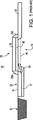
図4は、フォトセンシングデバイス、例えばフォトダイオード200、及びシリコン含有トランスファゲート、例えばポリシリコントランスファゲート125を含む、本発明の第1態様によるラインCMOS撮像素子APS100の後端部を示す断面図である。ポリシリコントランスファゲート125は、ダイオードを形成する、アノード(p型ドープ)領域と、隣接するカソード領域(n型ドープ)領域とを含んでいる。1つの非限定的な例において、ポリシリコントランスファゲート125はショットキーダイオードを含む。さらに、図4に示されているように、本明細書中で以下により詳細に説明するようなゲート・バリアac特性を改善するために、p型部分175aとn型部分175bとを有するポリゲートの表面上に、導電性構造、例えば部分シリサイド「ストラップ」190が形成されている。
FIG. 4 is a cross-sectional view illustrating a rear end portion of a line CMOS image sensor APS100 according to the first aspect of the present invention, including a photosensing device, such as a
図4に示されているように、部分シリサイドストラップ層190は、ポリシリコンゲート125のp型ドープ部分175aとn型ドープ部分175bとを電気的に接続する。さらに、図4に示されているように、部分シリサイド「ストラップ」190は、ゲートの境界から所定の距離を置いて形成されたエッジを有している。すなわち、シリサイドストラップ190は、ポリゲート層の各エッジ171,172から所定の距離、例えば距離d1及びd2だけ内方に設けられている。形成される部分シリサイドストラップの、内方へ引き込まれた距離d1及びd2は、等しい必要はない。すなわち、シリサイドストラップ190がp型部分175aからn型部分175bへ電気的に短絡する限り、ストラップは、ポリ幅の一部だけに被さるように形成される。こうして、図5Aの頂面図に示すように、シリサイドストラップ190は、ポリ幅の一部の最上部に形成されている。好ましい態様では、シリサイドストラップ190は、拡散領域130から離れた状態で形成されることは明らかである。
As shown in FIG. 4, the partial
図示はしていないが、図4に示されたCMOS撮像素子APS100構造の製造方法の一例をここで説明する。言うまでもなく、ダイオード構造、当業者に知られているような隣接するp型及びn型のゲートポリシリコン領域を有するトランスファゲートを形成するために、他の技術を用いることもできる。デバイス100は基板15上に形成され、基板15は、例えばSi、SiGe、SiC、SiGeC、GaAs、InP、InAs及びその他の半導体を含むバルク半導体であってよく、或いは、層状半導体、例えばシリコン・オン・インシュレータ(SOI)、SiC・オン・インシュレータ(SiCOI)、又はシリコンゲルマニウム・オン・インシュレータ(SGOI)であってもよい。説明のため、基板15は、例えばホウ素又はインジウム(III−V半導体の場合にはベリリウム又はマグネシウム)のようなp型ドーパント材料で、例えば1×1014〜1×1016cm-3まで軽度ドープされた第1導電性タイプのSi含有半導体基板である。次いで、基板15上に、標準的な堆積/成長技術によって誘電体材料層60を形成し、これは最終的なトランスファゲート誘電体を形成することになる。誘電体層は、例えば厚さ40Å〜100Åに形成されてよく、好適なゲート誘電体材料、例えば酸化物(例えばSiO2)、窒化物(例えば窒化ケイ素)、酸窒化物(例えば酸窒化Si)、N2O、NO、ZrO2、又はその他の同様の材料を含んでよい。1つの態様において、ゲート誘電体60は、酸化物、例えばSiO2、HfO2、ZrO2、Al2O3、TiO2、La2O3、SrTiO3、LaAlO3、及びこれらの混合物から成る。誘電体層60は、コンベンショナルな熱酸化を用いて、又は好適な堆積法、例えば化学蒸着、プラズマ支援化学蒸着、原子層堆積(ALD)、蒸発、反応性スパッタリング、化学溶液堆積、及びその他の同様の堆積法によって、Si含有半導体基板15の表面上に形成される。ゲート誘電体16は、上記方法の任意の組み合わせを利用して形成されてもよい。図示はしないが、誘電体層は、誘電体材料のスタックを含んでもよいことは明らかである。
Although not shown, an example of a manufacturing method of the CMOS image sensor APS100 structure shown in FIG. 4 will be described here. Of course, other techniques can be used to form a diode structure, a transfer gate having adjacent p-type and n-type gate polysilicon regions as known to those skilled in the art. The
次いで、コンベンショナルな堆積法、例えばCVD、プラズマ支援CVD、スパッタリング、めっき、蒸発、及びその他の同様の堆積法(例えば低圧CVD)を用いて、誘電体層60上に、シリコン含有層、例えば多結晶シリコンを形成する。ポリシリコン層は、約1kÅ〜2kÅの厚さに形成されてよいが、しかしこの範囲から外れていてもよい。或いは、シリコン含有層は、ポリシリコン層のスタックを含んでもよい。次いで、フォトリソグラフィ法、例えばマスク、例えばフォトレジスト層をポリシリコン層上に適用し、そして例えば、形成されるべきトランスファゲートの有効チャネル長を決定する長さにわたって、ゲート領域を画定するようにパターン化されたマスクを適用し、次いでレジストを現像し、そしてエッチング法を実施することにより、トランスファゲート125を形成する。基本的には、エッチング窓がレジストマスク内に設けられており、そのサイズ及び形状が、形成されるべきゲート領域の横方向のサイズ及び形状をほぼ画定する。次いで、ポリシリコン層及び誘電体層60又は誘電体層スタックの適正なエッチングを保証するように最適化された1種又は2種以上のエッチング法、例えば反応性イオン・エッチング(RIE)法を実施することにより、トランスファゲート構造をもたらす。
The silicon-containing layer, eg, polycrystalline, is then deposited on the
ゲート誘電体層上に固有のポリシリコン層を含むトランスファゲート構造を形成した後、トランスファゲート構造の一部を覆う後続のマスク堆積法、及びイオン注入法を実施することにより、第2導電性タイプから成るドーパント材料、例えばn型ドーパント材料(例えばリン、ヒ素又はアンチモン)をポリシリコン層内に注入することにより、n型ドープ・ゲート・ポリシリコン部分175bを形成する。n型ドーパント材料は、1×1017cm-3〜1×1020cm-3の添加濃度を達成するように注入されてよい。同様に、残りの部分、すなわちトランスファゲート構造の他方の側を覆う後続のマスク堆積法を用いて、イオン注入法を実施することにより、第1導電性タイプから成るドーパント材料、例えばp型ドーパント材料(例えばホウ素又はガリウム又はインジウム)をポリシリコン層内に注入することにより、図4に示されたp型ドープ・ゲート・ポリシリコン部分175aを形成する。p型ドーパント材料は、ゲートポリ中、1×1017cm-3〜1×1020cm-3の添加濃度を達成するように注入されてよい。或いは、ポリシリコンのドープは、プロセス中に既に存在する注入物を使用して、これらの注入物マスクを適正に使用することによって達成することもでき、同時に、これらの注入はチップ内の他の場所で実施される(一例としてソース・ドレイン注入物及びマスクが挙げられるが、他のものの可能である)。
After forming a transfer gate structure including a unique polysilicon layer on the gate dielectric layer, a subsequent mask deposition method that covers a portion of the transfer gate structure, and an ion implantation method are performed, thereby providing a second conductivity type. An n-type doped
なお、上記方法の変更形において、現場でドーピングされたn型、p型、又はn型及びp型両方のポリシリコン材料を、現場ドーピング堆積法又は堆積(例えばCVD、プラズマ支援など)に従って、ゲート誘電体層60の最上部に堆積することができる。現場ドープ堆積法は、例えば、ゲート誘電体が後続の高温アニーリングに耐えられないときに採用することができるのに対して、イオン注入及びアニールは、ゲート誘電体がこのような高温アニーリングに耐えられる材料であるときに採用することができる。
Note that in a variation of the above method, in-situ doped n-type, p-type, or both n-type and p-type polysilicon material is gated according to an in-situ doping deposition method or deposition (eg, CVD, plasma assisted, etc.). It can be deposited on top of the
追加の任意選択の工程において、当業者によく知られているコンベンショナルな堆積法によって、トランスファゲートのいずれかの側にゲート側壁スペース(図示せず)を形成することでき、ゲート側壁スペースは、任意のコンベンショナルな酸化物又は窒化物(例えばSi3N4)又は酸化物/窒化物を含んでよく、これらは次いで、RIE又は別の同様のエッチング法によってエッチングされる。スペーサの厚さは種々様々であってよいが、しかし典型的にはこれらの厚さは約5nm〜約150nmである。 In an additional optional step, a gate sidewall space (not shown) can be formed on either side of the transfer gate by conventional deposition methods well known to those skilled in the art. Conventional oxides or nitrides (eg, Si 3 N 4 ) or oxides / nitrides, which are then etched by RIE or another similar etching method. The thickness of the spacer can vary, but typically these thicknesses are from about 5 nm to about 150 nm.
トランスファゲート側壁スペーサを任意選択的に形成した後、フォトダイオード・ピニング領域180を提供するために、次の工程を実施する。この工程は、フォトレジスト層(図示せず)パターンを形成し、そしてゲートエッジとほぼ一致する、又はできる限り精密な整合許容誤差が与えられるマスク・エッジを形成するための当業者に知られた技術に従ってイオン注入マスクを作成することにより、ゲートのエッジと、形成された絶縁領域、例えばSTI領域(図示せず)との間の区域に開口を設ける。この開口に、フォトダイオードの電荷蓄積領域が形成されるようになっている。この開口は、図4に示されたp型ドーパント・ピニング領域180を形成するのに十分な濃度で、p型ドーパント材料、例えばホウ素から成るイオンを注入するのを可能にする。このピニング領域180は、スペーサ(図示せず)のエッジまで形成されてよい。活性p型ドーパント材料は、次いで1×10¹⁷〜1×1019cm-3の添加濃度でイオン注入される。或いは言うまでもなく、p型ピニング・フォトダイオード表面層180は、他の良く知られている技術によって形成することもできる。例えばp型表面層180は、ガス源プラズマ・ドープ法によって、フォトダイオードが形成されるべき領域全体にわたって堆積された現場ドープ層又はドープ酸化物層からp型ドーパントを拡散することにより形成されてよい。
After the transfer gate sidewall spacer is optionally formed, the following steps are performed to provide the
フォトダイオード素子200の基板表面のp型ドープ領域180の下側に、n型ドーパントをイオン注入するために、更なる工程を実施する。潜在的には、ピニング領域を形成するためにp型材料を注入したときと同じイオン注入マスクを使用することもでき、第2導電性タイプから成るドーパント材料、例えばn型ドーパント材料(例えばリン、ヒ素又はアンチモン)を注入するために、イオン注入法を実施することにより、イオン注入されたp型ピニング層180の下側に電荷捕集層を形成する。図4に示されたフォトダイオード190のn型ドープ領域170を形成するために、n型ドーパント材料は、より高いエネルギーレベルで注入される。活性n型ドーパント材料は、1×10¹⁶〜1×1018cm-3の添加濃度でイオン注入されてよい。図4に示されているように、光生成電子を捕集するための感光性電荷貯蔵領域170は、n型領域170のプロフィールを調整するために複数の注入物によって形成されてよい。
Further steps are performed to ion-implant the n-type dopant below the p-type doped
フォトダイオード200の形成に加えて、トランスファゲートの他方の側にn型浮動拡散領域130を形成する追加の工程が行われる。この工程は、フォトレジスト層を形成し、そしてゲートエッジとほぼ一致する、又はできる限り精密な整合許容誤差が与えられるマスク・エッジを形成するための当業者に知られた技術に従ってイオン注入マスクをパターン化してエッチングすることにより、図4に示されているような、又はゲート側壁スペーサ(図示せず)のエッジまでのn+型ドープ浮動拡散領域を形成するのに十分な濃度で、n型ドーパント材料、例えばリン、ヒ素又はアンチモンの注入を可能にする開口を提供することを含む。活性n+型ドーパント材料は、次いで1×10¹⁸〜1×10²⁰の添加濃度で、浮動拡散領域にイオン注入される。このイオン注入工程の結果として、n型ドーパント材料は加えて、ドープトランスファゲートポリシリコン層175b部分にも注入されてもよい。
In addition to forming the
図5A〜5Dに示すように、ポリシリコンゲート125を消費することにより、本発明による金属シリサイドストラップ190を形成するために、サリサイド法を実施する。
As shown in FIGS. 5A-5D, a salicide method is performed to form a
サリサイド法の第1工程は、よく知られた堆積技術を用いて、p型ドープ・ポリシリコン・ゲート層175a及びn型ドープ・ポリシリコン・ゲート層175b上に、ブランケット絶縁キャップを先ず形成することを含む。例えば、ポリシリコンゲート層175a,b上に、堆積法、物理蒸着又は化学蒸着を利用して、誘電体キャップ層を形成する。誘電キャップ層は、酸化物、窒化物、酸窒化物又はこれらの任意の組み合わせであってよい。1つの態様の場合、窒化物、例えばSi3N4が、誘電体キャップ層として採用される。誘電体キャップ層の厚さ、すなわち高さは約20nm〜約180nmであってよい。
The first step in the salicide method is to first form a blanket insulating cap on the p-type doped
次いで、典型的なリソグラフィ工程、すなわち、キャップ(例えば窒化物)誘電体層上にパターン化レジストマスクを形成する工程を用いて、形成されるべきシリサイドストラップの輪郭となる領域をエッチングする。リソグラフィ工程は、誘電体キャップ層の上面にフォトレジストを適用し、このフォトレジストを、所望のパターンの輻射線に当て、そしてコンベンショナルなレジスト現像剤を利用して露光されたフォトレジストを現像することを含む。フォトレジスト内のパターンは、1つ又は2つ以上の乾式エッチング工程を利用して、誘電体キャップ層に転写され、下に位置するポリシリコンゲート層を露出したままにし、そして特に、露出された下に位置するポリシリコン層内の両ドープ領域175a,bの隣接部分を露出させるように、誘電体キャップ層に窓を開ける。本発明によれば、所望されるパターンは、図5A〜5Dに示すように、形成されるべきシリサイドストラップの面積及び寸法である。こうして、例えば図5Aに示された本発明の頂面図に示すように、上に位置するキャップ誘電体(窒化物)層(図示せず)に適用されるフォトグラフィ・マスク、現像及びエッチング法は結果として、ゲートの長さに沿って各ゲートエッジ171,172のそれぞれから距離d1及びd2だけ内方に設けられた下に位置するポリシリコン層の露出領域195が生じる。この露出領域には、シリサイドコンタクトが形成されることになる。いくつかの態様の場合、パターン化フォトレジストは、パターンが誘電体キャップ層が誘電体キャップ層内に転写された後、除去されてよい。
A typical lithographic process, i.e., forming a patterned resist mask over a cap (e.g., nitride) dielectric layer, is then used to etch the regions that will outline the silicide strap to be formed. The lithography process applies a photoresist to the top surface of the dielectric cap layer, exposes the photoresist to the desired pattern of radiation, and develops the exposed photoresist using a conventional resist developer. including. The pattern in the photoresist is transferred to the dielectric cap layer using one or more dry etching processes, leaving the underlying polysilicon gate layer exposed and, in particular, exposed. A window is opened in the dielectric cap layer to expose adjacent portions of both doped
パターン化ゲートを形成する際に本発明において用いることができる好適な乾式乾燥エッチング法の一例としては、反応性イオン・エッチング、イオンビーム・エッチング、プラズマ・エッチング又はレーザーアブレーションが挙げられる。 Examples of suitable dry dry etching methods that can be used in the present invention in forming the patterned gate include reactive ion etching, ion beam etching, plasma etching, or laser ablation.
次いで、エッチングによりパターン化された窒化物層内に金属シリサイド(図示せず)を堆積する工程が実施されるので、露出された下に位置するポリシリコン層には、金属シリサイドが充填されるようになる。シリサイドストラップを形成する上で使用される金属は、金属シリサイドを形成するようにシリコンと反応することができる任意の金属を含む。このような金属の一例としては、Ti、Ta、W、Co、Mo、Ni、Pt、Pd又はこれらの金属が挙げられる。金属は、例えばスパッタリング、化学蒸着、シリサイド蒸発の物理蒸着(PVD)、化学溶液堆積、及びめっきなどを含む任意のコンベンショナルな堆積法を用いて堆積されてよい。 Next, a step of depositing metal silicide (not shown) in the nitride layer patterned by etching is performed, so that the exposed polysilicon layer is filled with metal silicide. become. The metal used in forming the silicide strap includes any metal that can react with silicon to form a metal silicide. Examples of such metals include Ti, Ta, W, Co, Mo, Ni, Pt, Pd, or these metals. The metal may be deposited using any conventional deposition method including, for example, sputtering, chemical vapor deposition, silicide vapor physical vapor deposition (PVD), chemical solution deposition, and plating.
シリサイドストラップ190の寸法を定義する露出ポリシリコン領域上に金属シリサイドを堆積した後、構造内にシリサイド相、好ましくは金属シリサイドの最低抵抗率相を示すシリサイドを形成するために、熱アニール法が採用される。アニールは、図4に示された金属シリサイド層190を形成するために金属シリサイドが下に位置するポリシリコンと反応するようにする、当業者によく知られた環境及び温度を利用して実施される。1つの態様の場合、金属シリサイドはCo、特に当業者に良く知られた2工程アニール法を用いるCoSi2形態を含んでよい。本発明の別の態様の場合、金属シリサイドはNi又はPtであり、NiSi及びPtSiは単一アニール工程を用いて形成される。次いで、構造から非反応性金属シリサイドを除去するために、選択的な湿式エッチング工程を採用することができる。
Thermal annealing is employed to form a silicide phase in the structure, preferably the lowest resistivity phase of the metal silicide, after depositing a metal silicide on the exposed polysilicon region defining the dimensions of the
1つの態様において、ウエハーを次いで、ポリシリコン層部分175a,bと反応するための窒素環境中でほぼ30秒にわたって約500℃〜約800℃でアニールすることにより、導電性シリサイドストラップ190を形成する。
In one embodiment, the
上述の本発明による金属シリサイドゲート処理が完了した後、トランジスタ間、及びトランジスタと外部コンタクトとの相互接続構造を形成するためのコンベンショナルな処置を採用することができる。 After the above-described metal silicide gate process according to the present invention is completed, conventional measures can be employed to form interconnect structures between transistors and between transistors and external contacts.
図5Bは、図5Aに示した本発明の態様の第1変更形に従って形成されたCMOS APSセル100’を示す頂面図である。ここでは、本明細書中に記載された方法を用いてシリサイドストラップ191が形成され、このシリサイドストラップ191は、境界ゲートのエッジから距離d1及びd2だけ内方に形成されたエッジを有しているが、しかしポリシリコンのほぼ全幅にわたって延びるように形成されている。このように、例えば、図5Aに関して本明細書中に説明したサリサイド法を参照すると、図5Bに示すように、上に位置するキャップ誘電体(窒化物)層(図示せず)に適用されるフォトグラフィ・マスク、現像及びエッチング法は結果として、例えば、ゲートの長さに沿って各ゲートエッジ171,172のそれぞれから距離d1及びd2だけ内方に設けられるが、しかしポリ層の両エッジまでほぼ全幅にわたって距離dwだけ延びる下に位置するポリシリコン層の露出領域196が形成されることになる。
FIG. 5B is a top view showing a
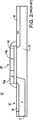
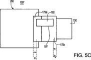
図5Cは、図5Aに示した本発明の態様の第2変更形に従って形成されたCMOS APSセル100''を示す頂面図である。ここでは、本明細書中に記載された方法を用いてシリサイドストラップ192が形成され、このシリサイドストラップ192は、境界ゲートのエッジから距離d1及びd2だけ内方に形成されたエッジを有しているが、しかしポリゲートの短い距離にわたって延びるように形成されている。このように、例えば、図5Aに関して本明細書中に説明したサリサイド法を参照すると、図5Cに示すように、上に位置するキャップ誘電体(窒化物)層(図示せず)に適用されるフォトグラフィ・マスク、現像及びエッチング法は結果として、例えば、ゲートの長さに沿って各ゲートエッジ171,172のそれぞれから距離d1及びd2だけ内方に設けられるが、しかしポリゲートの短い距離だけにわたって延びる下に位置するポリシリコン層の露出領域197が形成されることになる。
FIG. 5C is a top view showing a
本発明の更なる態様によれば、CMOS撮像素子APSトランスファゲートのためのシリサイドストラップは、導電チャネル上に直接には位置していないポリシリコンゲート部分上に形成することができる(すなわちn領域とn領域とが、或る場所のストラップによって短絡される限り)。図5Dは、図5Aに示した本発明の態様の第3変更形に従って形成されたCMOS APSセル100'''を示す頂面図である。ここでは、本明細書中に記載された方法を用いてシリサイドストラップ193が形成され、このシリサイドストラップ193は、境界ゲートのエッジから所定の距離だけ内方に形成されたエッジを有しており、しかもポリゲートの短い距離にわたって延びるように形成されている。しかしながら、このストラップ193は、トランスファデバイスのためのチャネル領域を画定するそのゲート部分175a,bから、ずらされている。すなわち、シリサイドストラップ193は、導電チャネル上に直接には位置していないポリシリコンゲート部分上に形成することができる。このように、例えば、図5Aに関して本明細書中に説明したサリサイド法を参照すると、図5Dに示すように、上に位置するキャップ誘電体(窒化物)層(図示せず)に適用されるフォトグラフィ・マスク、現像及びエッチング法は結果として、ゲートの長さに沿って各ゲートエッジ171,172のそれぞれから所定の距離だけ内方に設けられ、しかも、例えばデバイスのチャネル領域に直接には被さらない領域内で、ポリゲートの短い距離だけにわたって延びる下に位置するポリシリコン層の露出領域198が形成されることになる。
According to a further aspect of the invention, a silicide strap for a CMOS imager APS transfer gate can be formed on a polysilicon gate portion that is not directly over the conductive channel (ie, the n region and as long as the n region is shorted by a strap in place). FIG. 5D is a top view showing a
言うまでもなく、上記シリサイドコンタクト構造以外に、トランスファゲートポリのアノード部分175aとカソード部分175bとを電気的に短絡するためのいずれの導電性構造をも実現することもできる。しかし、光検出領域と浮動拡散領域とがシリサイド非含有であることは必須である。
Needless to say, in addition to the silicide contact structure, any conductive structure for electrically short-circuiting the
図5A〜5Dに示し、これらの図面に関して説明した構造の利点は、暗電流漏れを低減するために、フォトダイオードに高いバリアが存在すること、及び、より低いラグのために、浮動拡散領域に低いバリアが存在することである。シリサイドストラップは、ダイオード挙動が、ゲートの一方又は他方の側が中間電圧まで浮動するのを許すのを防止する。 The advantages of the structure shown in FIGS. 5A-5D and described with respect to these drawings are that there is a high barrier in the photodiode to reduce dark current leakage, and in the floating diffusion region because of the lower lag. There is a low barrier. The silicide strap prevents the diode behavior from allowing one or the other side of the gate to float to an intermediate voltage.
図6を参照すると、図5A〜5Dに示された本発明のそれぞれの態様に従って形成されたCMOSアクティブピクセルセンサ(APS)セル100〜100'''を有する画像センサ302を実現するカメラデバイス300の側面図が示されている。
Referring to FIG. 6, a
本発明の好ましい態様と考えられるものを図示して説明してきたが、もちろん、本発明の思想を逸脱することなしに、形態又は詳細の種々の改変及び変更を容易に加え得ることは明らかである。例えば、本明細書中に記載された好ましい態様は、n型フォトダイオード及びp型ピニング層及びnFETに向けられているが、本発明の原理をp型フォトダイオード、及びpFETを有するn型ピニング層に適用することができる。従って、本発明は、記述・例示された形態そのままのものに限定されるものではなく、添付の特許請求の範囲の中に含まれる全ての改変形に及ぶものと解釈されるべきである。 While what has been considered as preferred embodiments of the invention have been illustrated and described, it will be appreciated that various changes and modifications in form or detail may readily be made without departing from the spirit of the invention. . For example, while the preferred embodiments described herein are directed to n-type photodiodes and p-type pinning layers and nFETs, the principles of the present invention are p-type photodiodes and n-type pinning layers having pFETs. Can be applied to. Accordingly, the invention is not limited to the precise forms described and illustrated, but is to be construed as extending to all modifications that fall within the scope of the appended claims.
Claims (3)
該基板上に形成されたゲート誘電体層と、該ゲート誘電体層上に形成されたデュアル仕事関数ゲート導体層とを含むトランスファゲートデバイス、
該デュアル仕事関数ゲート導体層は、第1導電性タイプ材料から成る第1ドープ領域及び第2導電性タイプ材料から成る第2ドープ領域を含む;
入射する光に応答して電荷キャリヤを捕集するための、前記トランスファゲートデバイスの前記第1ドープ領域に隣接する基板表面に又は該基板表面の下側に形成されたフォトセンシングデバイス;
前記トランスファゲートデバイスの前記第2ドープ領域に隣接する前記基板表面に形成された、第2導電性タイプ材料から成る拡散領域、
該トランスファゲートデバイスは、前記フォトセンシングデバイスと前記拡散領域との間の電荷移動を可能にするチャネル領域を形成している;及び
前記トランスファゲートデバイスの第1導電性タイプ材料から成る前記第1ドープ領域と、前記トランスファゲートデバイスの第2導電性タイプ材料から成る前記第2ドープ領域とを電気的にカップリングするための、前記デュアル仕事関数ゲート導体層の最上部に形成されたシリサイド構造
を含んで成るアクティブピクセルセンサ(APS)セル構造であって、
前記シリサイド構造が、面積寸法で、前記デュアル仕事関数ゲート導体層の面積寸法よりも小さいアクティブピクセルセンサ(APS)セル構造。A substrate comprising a first conductive type material;
A transfer gate device comprising a gate dielectric layer formed on the substrate and a dual work function gate conductor layer formed on the gate dielectric layer;
The dual work function gate conductor layer includes a first doped region comprising a first conductive type material and a second doped region comprising a second conductive type material;
A photo-sensing device formed on or under the substrate surface adjacent to the first doped region of the transfer gate device for collecting charge carriers in response to incident light;
A diffusion region made of a second conductive type material formed on the substrate surface adjacent to the second doped region of the transfer gate device;
The transfer gate device forms a channel region that allows charge transfer between the photo-sensing device and the diffusion region; and the first doping comprising the first conductive type material of the transfer gate device A silicide structure formed on top of the dual work function gate conductor layer for electrically coupling a region and the second doped region of the second conductivity type material of the transfer gate device. An active pixel sensor (APS) cell structure comprising:
An active pixel sensor (APS) cell structure in which the silicide structure is smaller in area size than the area size of the dual work function gate conductor layer .
該基板上に形成されたゲート誘電体層及び該ゲート誘電体層上に形成されたデュアル仕事関数ゲート導体層を含むトランスファゲートデバイスを形成すること、Forming a transfer gate device comprising a gate dielectric layer formed on the substrate and a dual work function gate conductor layer formed on the gate dielectric layer;
該デュアル仕事関数ゲート導体層は、第1導電性タイプ材料から成る第1ドープ領域及び第2導電性タイプ材料から成る第2ドープ領域を含む;The dual work function gate conductor layer includes a first doped region comprising a first conductive type material and a second doped region comprising a second conductive type material;
前記トランスファゲートデバイスの前記第1ドープ領域に隣接する基板表面に又は該基板表面の下側に形成された、入射する光に応答して電荷キャリヤを捕集するための、フォトセンシングデバイスを形成すること;Forming a photo-sensing device for collecting charge carriers in response to incident light, formed on or under the substrate surface adjacent to the first doped region of the transfer gate device thing;
前記トランスファゲートデバイスの前記第2ドープ領域に隣接する前記基板表面ところに、第2導電性タイプ材料から成る拡散領域を形成すること、Forming a diffusion region of a second conductive type material at a surface of the substrate adjacent to the second doped region of the transfer gate device;
前記トランスファゲートデバイスは、前記フォトセンシングデバイスと前記拡散領域との間の電荷移動を可能にするチャネル領域を形成する;そしてThe transfer gate device forms a channel region that allows charge transfer between the photo-sensing device and the diffusion region; and
前記トランスファゲートデバイスの第1導電性タイプ材料から成る前記第1ドープ領域と、前記トランスファゲートデバイスの第2導電性タイプ材料から成る前記第2ドープ領域とを電気的にカップリングするための、前記デュアル仕事関数ゲート導体層の最上部にシリサイド構造を形成することFor electrically coupling the first doped region of the first conductive type material of the transfer gate device and the second doped region of the second conductive type material of the transfer gate device; Forming a silicide structure on top of dual work function gate conductor layer
を含んで成るアクティブピクセルセンサ(APS)セル構造を形成する方法であって、A method of forming an active pixel sensor (APS) cell structure comprising:
前記シリサイド構造が、面積寸法で、前記デュアル仕事関数ゲート導体層の面積寸法よりも小さいアクティブピクセルセンサ(APS)セル構造を形成する方法。A method of forming an active pixel sensor (APS) cell structure in which the silicide structure is smaller in area size than the area size of the dual work function gate conductor layer.
Applications Claiming Priority (3)
| Application Number | Priority Date | Filing Date | Title |
|---|---|---|---|
| US11/565,801 US7675097B2 (en) | 2006-12-01 | 2006-12-01 | Silicide strapping in imager transfer gate device |
| US11/565,801 | 2006-12-01 | ||
| PCT/US2007/024684 WO2008069994A2 (en) | 2006-12-01 | 2007-11-30 | Silicide strapping in imager transfer gate device |
Publications (3)
| Publication Number | Publication Date |
|---|---|
| JP2010512004A JP2010512004A (en) | 2010-04-15 |
| JP2010512004A5 JP2010512004A5 (en) | 2011-01-20 |
| JP5096483B2 true JP5096483B2 (en) | 2012-12-12 |
Family
ID=39434223
Family Applications (1)
| Application Number | Title | Priority Date | Filing Date |
|---|---|---|---|
| JP2009539352A Active JP5096483B2 (en) | 2006-12-01 | 2007-11-30 | Silicide straps in image sensor transfer gate devices |
Country Status (7)
| Country | Link |
|---|---|
| US (2) | US7675097B2 (en) |
| EP (1) | EP2089905B1 (en) |
| JP (1) | JP5096483B2 (en) |
| KR (1) | KR101437194B1 (en) |
| CN (1) | CN101281918B (en) |
| TW (1) | TWI420659B (en) |
| WO (1) | WO2008069994A2 (en) |
Families Citing this family (38)
| Publication number | Priority date | Publication date | Assignee | Title |
|---|---|---|---|---|
| US7838371B2 (en) * | 2006-11-06 | 2010-11-23 | Nxp B.V. | Method of manufacturing a FET gate |
| US7675097B2 (en) | 2006-12-01 | 2010-03-09 | International Business Machines Corporation | Silicide strapping in imager transfer gate device |
| KR100810423B1 (en) * | 2006-12-27 | 2008-03-04 | 동부일렉트로닉스 주식회사 | Image sensor and method of manufacturing image sensor |
| US20080217679A1 (en) * | 2007-03-08 | 2008-09-11 | Macronix International Co., Ltd. | Memory unit structure and operation method thereof |
| KR20090003854A (en) * | 2007-07-05 | 2009-01-12 | 삼성전자주식회사 | Image sensor and method of fabricating the same |
| US8110465B2 (en) | 2007-07-30 | 2012-02-07 | International Business Machines Corporation | Field effect transistor having an asymmetric gate electrode |
| US7741217B2 (en) * | 2007-10-25 | 2010-06-22 | International Business Machines Corporation | Dual workfunction silicide diode |
| US8743247B2 (en) * | 2008-01-14 | 2014-06-03 | International Business Machines Corporation | Low lag transfer gate device |
| US8227844B2 (en) * | 2008-01-14 | 2012-07-24 | International Business Machines Corporation | Low lag transfer gate device |
| TWI347009B (en) * | 2008-02-04 | 2011-08-11 | Jack Kuo | Continuous multigate transistors |
| US20090261393A1 (en) * | 2008-04-18 | 2009-10-22 | United Microelectronics Corp. | Composite transfer gate and fabrication thereof |
| JP5271104B2 (en) * | 2009-02-13 | 2013-08-21 | 浜松ホトニクス株式会社 | Linear image sensor |
| JP5091886B2 (en) | 2009-02-13 | 2012-12-05 | 浜松ホトニクス株式会社 | Image sensor |
| US20100314667A1 (en) * | 2009-06-11 | 2010-12-16 | Omnivision Technologies, Inc. | Cmos pixel with dual-element transfer gate |
| US9000500B2 (en) * | 2009-12-30 | 2015-04-07 | Omnivision Technologies, Inc. | Image sensor with doped transfer gate |
| US8299505B2 (en) | 2011-02-17 | 2012-10-30 | International Business Machines Corporation | Pixel sensor cell with a dual work function gate electode |
| EP2708021B1 (en) | 2011-05-12 | 2019-07-10 | DePuy Synthes Products, Inc. | Image sensor with tolerance optimizing interconnects |
| US9070784B2 (en) | 2011-07-22 | 2015-06-30 | Taiwan Semiconductor Manufacturing Company, Ltd. | Metal gate structure of a CMOS semiconductor device and method of forming the same |
| JP2013084834A (en) * | 2011-10-12 | 2013-05-09 | Sharp Corp | Solid-state imaging element and method of manufacturing the same |
| US9698185B2 (en) * | 2011-10-13 | 2017-07-04 | Omnivision Technologies, Inc. | Partial buried channel transfer device for image sensors |
| US9000527B2 (en) | 2012-05-15 | 2015-04-07 | Apple Inc. | Gate stack with electrical shunt in end portion of gate stack |
| WO2014002365A1 (en) * | 2012-06-26 | 2014-01-03 | パナソニック株式会社 | Solid-state image pickup apparatus and method for manufacturing same |
| EP2877079B1 (en) | 2012-07-26 | 2021-04-21 | DePuy Synthes Products, Inc. | Camera system with minimal area monolithic cmos image sensor |
| US8809925B2 (en) * | 2012-10-11 | 2014-08-19 | Omnivision Technologies, Inc. | Partial buried channel transfer device in image sensors |
| US8912584B2 (en) * | 2012-10-23 | 2014-12-16 | Apple Inc. | PFET polysilicon layer with N-type end cap for electrical shunt |
| EP2967286B1 (en) | 2013-03-15 | 2021-06-23 | DePuy Synthes Products, Inc. | Minimize image sensor i/o and conductor counts in endoscope applications |
| US10517469B2 (en) | 2013-03-15 | 2019-12-31 | DePuy Synthes Products, Inc. | Image sensor synchronization without input clock and data transmission clock |
| KR102089682B1 (en) | 2013-07-15 | 2020-03-16 | 삼성전자 주식회사 | Semiconductor device and method for fabricating the same |
| CN103456756A (en) * | 2013-09-26 | 2013-12-18 | 哈尔滨工程大学 | Active pixel structure and manufacture method thereof |
| US9526468B2 (en) | 2014-09-09 | 2016-12-27 | General Electric Company | Multiple frame acquisition for exposure control in X-ray medical imagers |
| JP6668600B2 (en) * | 2015-03-19 | 2020-03-18 | セイコーエプソン株式会社 | Solid-state imaging device and method of manufacturing the same |
| US10254389B2 (en) | 2015-11-06 | 2019-04-09 | Artilux Corporation | High-speed light sensing apparatus |
| TWI724164B (en) * | 2017-05-05 | 2021-04-11 | 聯華電子股份有限公司 | Semiconductor device and method for fabricating the same |
| US11393867B2 (en) * | 2017-12-06 | 2022-07-19 | Facebook Technologies, Llc | Multi-photodiode pixel cell |
| US11105928B2 (en) | 2018-02-23 | 2021-08-31 | Artilux, Inc. | Light-sensing apparatus and light-sensing method thereof |
| TWI788246B (en) * | 2018-02-23 | 2022-12-21 | 美商光程研創股份有限公司 | Photo-detecting apparatus |
| CN110108919A (en) * | 2019-04-16 | 2019-08-09 | 天津大学 | The measurement method of PPD pinning voltage in a kind of pixel |
| US20240030246A1 (en) * | 2020-12-21 | 2024-01-25 | Sony Semiconductor Solutions Corporation | Imaging device and electronic device |
Family Cites Families (21)
| Publication number | Priority date | Publication date | Assignee | Title |
|---|---|---|---|---|
| JP2817518B2 (en) * | 1991-06-21 | 1998-10-30 | 松下電器産業株式会社 | Semiconductor device and manufacturing method thereof |
| DE69630944D1 (en) | 1996-03-29 | 2004-01-15 | St Microelectronics Srl | High voltage MOS transistor and manufacturing method |
| EP0936667A1 (en) * | 1998-01-20 | 1999-08-18 | Lucent Technologies Inc. | Lattice matched barrier for dual doped polysilicon gates |
| US6333205B1 (en) | 1999-08-16 | 2001-12-25 | Micron Technology, Inc. | CMOS imager with selectively silicided gates |
| JP3782297B2 (en) * | 2000-03-28 | 2006-06-07 | 株式会社東芝 | Solid-state imaging device and manufacturing method thereof |
| JP4398917B2 (en) | 2000-03-28 | 2010-01-13 | 株式会社東芝 | Solid-state imaging device and manufacturing method thereof |
| EP1308032A2 (en) * | 2000-08-04 | 2003-05-07 | Foveon, Inc. | All-electronic high-resolution digital still camera |
| US6794252B2 (en) * | 2001-09-28 | 2004-09-21 | Texas Instruments Incorporated | Method and system for forming dual work function gate electrodes in a semiconductor device |
| TWI296062B (en) * | 2001-12-28 | 2008-04-21 | Sanyo Electric Co | Liquid crystal display device |
| US7335958B2 (en) * | 2003-06-25 | 2008-02-26 | Micron Technology, Inc. | Tailoring gate work-function in image sensors |
| US7064406B2 (en) | 2003-09-03 | 2006-06-20 | Micron Technology, Inc. | Supression of dark current in a photosensor for imaging |
| US7205584B2 (en) | 2003-12-22 | 2007-04-17 | Micron Technology, Inc. | Image sensor for reduced dark current |
| US7214575B2 (en) | 2004-01-06 | 2007-05-08 | Micron Technology, Inc. | Method and apparatus providing CMOS imager device pixel with transistor having lower threshold voltage than other imager device transistors |
| JP2005260077A (en) * | 2004-03-12 | 2005-09-22 | Matsushita Electric Ind Co Ltd | Solid-state image pickup element, its manufacturing method and camera using element |
| JP4546201B2 (en) * | 2004-03-17 | 2010-09-15 | ルネサスエレクトロニクス株式会社 | Manufacturing method of semiconductor device |
| US7288788B2 (en) | 2004-12-03 | 2007-10-30 | International Business Machines Corporation | Predoped transfer gate for an image sensor |
| US7217968B2 (en) | 2004-12-15 | 2007-05-15 | International Business Machines Corporation | Recessed gate for an image sensor |
| JP4533155B2 (en) * | 2005-01-12 | 2010-09-01 | 富士通セミコンダクター株式会社 | Semiconductor device and manufacturing method thereof |
| US7115924B1 (en) * | 2005-06-03 | 2006-10-03 | Avago Technologies Sensor Ip Pte. Ltd. | Pixel with asymmetric transfer gate channel doping |
| JP4847828B2 (en) * | 2006-09-22 | 2011-12-28 | 旭化成エレクトロニクス株式会社 | Manufacturing method of CMOS image sensor |
| US7675097B2 (en) | 2006-12-01 | 2010-03-09 | International Business Machines Corporation | Silicide strapping in imager transfer gate device |
-
2006
- 2006-12-01 US US11/565,801 patent/US7675097B2/en active Active
-
2007
- 2007-11-15 CN CN2007101869334A patent/CN101281918B/en active Active
- 2007-11-30 WO PCT/US2007/024684 patent/WO2008069994A2/en active Application Filing
- 2007-11-30 KR KR1020097011278A patent/KR101437194B1/en active IP Right Grant
- 2007-11-30 TW TW096145709A patent/TWI420659B/en active
- 2007-11-30 JP JP2009539352A patent/JP5096483B2/en active Active
- 2007-11-30 EP EP07867600.4A patent/EP2089905B1/en active Active
-
2010
- 2010-02-03 US US12/699,419 patent/US8158453B2/en active Active
Also Published As
| Publication number | Publication date |
|---|---|
| WO2008069994A2 (en) | 2008-06-12 |
| US20100136733A1 (en) | 2010-06-03 |
| US20080128767A1 (en) | 2008-06-05 |
| JP2010512004A (en) | 2010-04-15 |
| CN101281918A (en) | 2008-10-08 |
| EP2089905B1 (en) | 2014-01-22 |
| WO2008069994A3 (en) | 2008-08-28 |
| KR20090087896A (en) | 2009-08-18 |
| EP2089905A2 (en) | 2009-08-19 |
| US8158453B2 (en) | 2012-04-17 |
| TW200837941A (en) | 2008-09-16 |
| US7675097B2 (en) | 2010-03-09 |
| TWI420659B (en) | 2013-12-21 |
| CN101281918B (en) | 2010-12-08 |
| KR101437194B1 (en) | 2014-09-03 |
Similar Documents
| Publication | Publication Date | Title |
|---|---|---|
| JP5096483B2 (en) | Silicide straps in image sensor transfer gate devices | |
| US8227844B2 (en) | Low lag transfer gate device | |
| US7888156B2 (en) | Predoped transfer gate for a CMOS image sensor | |
| US8743247B2 (en) | Low lag transfer gate device | |
| US7217968B2 (en) | Recessed gate for an image sensor | |
| US7205591B2 (en) | Pixel sensor cell having reduced pinning layer barrier potential and method thereof | |
| US6921934B2 (en) | Double pinned photodiode for CMOS APS and method of formation | |
| US7141836B1 (en) | Pixel sensor having doped isolation structure sidewall | |
| US8268662B2 (en) | Fabricating method of complementary metal-oxide-semiconductor (CMOS) image sensor | |
| US7528427B2 (en) | Pixel sensor cell having asymmetric transfer gate with reduced pinning layer barrier potential | |
| US7768087B2 (en) | Photodiode, solid slate image sensor, and method of manufacturing the same | |
| US8004027B2 (en) | Image sensor and manufacturing method thereof | |
| US7429496B2 (en) | Buried photodiode for image sensor with shallow trench isolation technology | |
| US20070023796A1 (en) | Pinning layer for pixel sensor cell and method thereof | |
| US20060270091A1 (en) | Pinned photodiode integrated with trench isolation and fabrication method | |
| US8679884B2 (en) | Methods for manufacturing semiconductor apparatus and CMOS image sensor | |
| KR20050029455A (en) | Cmos image sensor and method for manufacturing the same | |
| US20060284223A1 (en) | CMOS image sensor and manufacturing method thereof | |
| KR100790213B1 (en) | Method for fabricating image sensor |
Legal Events
| Date | Code | Title | Description |
|---|---|---|---|
| A521 | Request for written amendment filed |
Free format text: JAPANESE INTERMEDIATE CODE: A523 Effective date: 20101126 |
|
| A621 | Written request for application examination |
Free format text: JAPANESE INTERMEDIATE CODE: A621 Effective date: 20101126 |
|
| A711 | Notification of change in applicant |
Free format text: JAPANESE INTERMEDIATE CODE: A711 Effective date: 20111031 |
|
| A521 | Request for written amendment filed |
Free format text: JAPANESE INTERMEDIATE CODE: A821 Effective date: 20111031 |
|
| A521 | Request for written amendment filed |
Free format text: JAPANESE INTERMEDIATE CODE: A523 Effective date: 20111125 |
|
| TRDD | Decision of grant or rejection written | ||
| A01 | Written decision to grant a patent or to grant a registration (utility model) |
Free format text: JAPANESE INTERMEDIATE CODE: A01 Effective date: 20120821 |
|
| A01 | Written decision to grant a patent or to grant a registration (utility model) |
Free format text: JAPANESE INTERMEDIATE CODE: A01 |
|
| A977 | Report on retrieval |
Free format text: JAPANESE INTERMEDIATE CODE: A971007 Effective date: 20120823 |
|
| A61 | First payment of annual fees (during grant procedure) |
Free format text: JAPANESE INTERMEDIATE CODE: A61 Effective date: 20120920 |
|
| R150 | Certificate of patent or registration of utility model |
Ref document number: 5096483 Country of ref document: JP Free format text: JAPANESE INTERMEDIATE CODE: R150 Free format text: JAPANESE INTERMEDIATE CODE: R150 |
|
| FPAY | Renewal fee payment (event date is renewal date of database) |
Free format text: PAYMENT UNTIL: 20150928 Year of fee payment: 3 |
|
| R250 | Receipt of annual fees |
Free format text: JAPANESE INTERMEDIATE CODE: R250 |
|
| R250 | Receipt of annual fees |
Free format text: JAPANESE INTERMEDIATE CODE: R250 |
|
| R250 | Receipt of annual fees |
Free format text: JAPANESE INTERMEDIATE CODE: R250 |
|
| R250 | Receipt of annual fees |
Free format text: JAPANESE INTERMEDIATE CODE: R250 |
|
| R250 | Receipt of annual fees |
Free format text: JAPANESE INTERMEDIATE CODE: R250 |
|
| R250 | Receipt of annual fees |
Free format text: JAPANESE INTERMEDIATE CODE: R250 |
|
| R250 | Receipt of annual fees |
Free format text: JAPANESE INTERMEDIATE CODE: R250 |
|
| R250 | Receipt of annual fees |
Free format text: JAPANESE INTERMEDIATE CODE: R250 |
|
| R250 | Receipt of annual fees |
Free format text: JAPANESE INTERMEDIATE CODE: R250 |
|
| R250 | Receipt of annual fees |
Free format text: JAPANESE INTERMEDIATE CODE: R250 |