JP5088064B2 - Game machine - Google Patents

Game machine Download PDF

Info

Publication number
JP5088064B2
JP5088064B2 JP2007246331A JP2007246331A JP5088064B2 JP 5088064 B2 JP5088064 B2 JP 5088064B2 JP 2007246331 A JP2007246331 A JP 2007246331A JP 2007246331 A JP2007246331 A JP 2007246331A JP 5088064 B2 JP5088064 B2 JP 5088064B2
Authority
JP
Japan
Prior art keywords
game balls
ball
unit
payout
game
Prior art date
Legal status (The legal status is an assumption and is not a legal conclusion. Google has not performed a legal analysis and makes no representation as to the accuracy of the status listed.)
Active
Application number
JP2007246331A
Other languages
Japanese (ja)
Other versions
JP2009072482A (en
JP2009072482A5 (en
Inventor
浩二 江島
Current Assignee (The listed assignees may be inaccurate. Google has not performed a legal analysis and makes no representation or warranty as to the accuracy of the list.)
Sanyo Bussan Co Ltd
Original Assignee
Sanyo Bussan Co Ltd
Priority date (The priority date is an assumption and is not a legal conclusion. Google has not performed a legal analysis and makes no representation as to the accuracy of the date listed.)
Filing date
Publication date
Application filed by Sanyo Bussan Co Ltd filed Critical Sanyo Bussan Co Ltd
Priority to JP2007246331A priority Critical patent/JP5088064B2/en
Publication of JP2009072482A publication Critical patent/JP2009072482A/en
Publication of JP2009072482A5 publication Critical patent/JP2009072482A5/ja
Application granted granted Critical
Publication of JP5088064B2 publication Critical patent/JP5088064B2/en
Active legal-status Critical Current
Anticipated expiration legal-status Critical

Links

Images

Landscapes

  • Pinball Game Machines (AREA)

Description

本発明は、遊技機に関するものである。   The present invention relates to a gaming machine.

遊技機の一種であるパチンコ機は、パチンコ機内部にて遊技球を貯留するための貯留タンクを備えている。貯留タンクに貯留されている遊技球は、誘導通路部を通じて、遊技機前面部の球受け皿へ誘導される。また、誘導通路部の途中位置には払出装置が設けられており、誘導通路部により誘導される遊技球は払出装置内にて一旦停止される。詳細には、払出装置には回転体などの球止め手段が内蔵されており、誘導通路部により誘導される遊技球は球止め手段により一旦停止される。払出装置は制御装置と電気的に接続されている。そして、遊技領域に設けられた入賞口へ遊技球が入賞したことに基づいて制御装置に賞球数情報が記憶され、球止め手段が払出動作を実行するように制御装置により払出装置が駆動制御されることで、上記一旦停止されていた遊技球は球受け皿に払い出される(例えば、特許文献1参照)。
特開2007−167431号公報
A pachinko machine, which is a type of gaming machine, includes a storage tank for storing game balls inside the pachinko machine. The game balls stored in the storage tank are guided to the ball tray on the front portion of the gaming machine through the guide passage portion. In addition, a payout device is provided in the middle of the guide passage portion, and the game ball guided by the guide passage portion is temporarily stopped in the payout device. Specifically, the payout device incorporates ball stopping means such as a rotating body, and the game ball guided by the guide passage is temporarily stopped by the ball stopping means. The dispensing device is electrically connected to the control device. Then, based on the fact that a game ball has won a prize opening provided in the game area, information on the number of winning balls is stored in the control device, and the control device drives and controls the payout device so that the ball stopper means executes the payout operation. As a result, the game ball once stopped is paid out to the ball tray (see, for example, Patent Document 1).
JP 2007-167431 A

ここで、例えばパチンコ機を中古で流通させる場合、パチンコ機内の遊技球が全て抜き出される。遊技球には遊技ホール毎に固有の模様などが付されており、中古での流通に際してパチンコ機内の遊技球を全て抜き出すことで、遊技ホール間で異なる遊技球が混ざらないようにすることができる。   Here, for example, when a pachinko machine is used and distributed, all game balls in the pachinko machine are extracted. The game balls have unique patterns for each game hall. By extracting all the game balls in the pachinko machine during second-hand distribution, it is possible to prevent different game balls from being mixed between the game halls. .

遊技球を抜き出すための構成は以下のとおりである。誘導通路部には払出装置よりも上流側にパチンコ機外部(例えば、遊技ホールの島設備)へ通じる排出通路部が設けられており、さらには当該排出通路部の入口部分には切換部が設けられている。切換部は、それよりも上流側の遊技球を払出装置側又は排出通路部側のいずれかに誘導するように切り換え可能に設けられている。切換部を排出通路部側に誘導するように切り換えることで、それよりも上流側の遊技球がパチンコ機外部に排出される。但し、切換部から払出装置内の球停止位置までの間には所定数の遊技球が待機可能な間隔が存在しており、切換部を排出通路部側に誘導するように切り換えたとしても、両者の間に遊技球が残ってしまう。これに対して、遊技領域を露出させて入賞口への遊技球の入球を手入れで行い払出装置を動作させることで、上記残存遊技球の排出を行うことができる。   The configuration for extracting a game ball is as follows. The guide passage section is provided with a discharge passage section that leads to the outside of the pachinko machine (for example, the island facility of the game hall) upstream from the payout device, and further, a switching section is provided at the entrance of the discharge passage section. It has been. The switching portion is provided so as to be able to switch so as to guide the game ball on the upstream side to either the payout device side or the discharge passage portion side. By switching so that the switching portion is guided to the discharge passage portion side, the game ball on the upstream side is discharged to the outside of the pachinko machine. However, there is an interval in which a predetermined number of game balls can stand by between the switching unit and the ball stop position in the payout device, and even if the switching unit is switched to guide to the discharge passage unit side, A game ball remains between the two. On the other hand, the remaining game balls can be discharged by exposing the game area, cleaning the game balls into the winning opening, and operating the payout device.

この場合に、上記のようにパチンコ機が中古で流通する場合、その流通過程で制御装置が不正な制御装置に交換されてしまうことが懸念される。そして、その発見が行われないと、流通先の遊技ホールが多大な不利益を被ってしまうおそれがあり好ましくない。   In this case, when pachinko machines are used and distributed as described above, there is a concern that the control device may be replaced with an unauthorized control device in the distribution process. If the discovery is not performed, there is a possibility that the game hall of the distribution destination may suffer a great disadvantage.

一方、パチンコ機が中古で流通する場合以外にも、遊技ホールなどにおいて、払出装置や、誘導通路部における払出装置よりも上流側を構成する通路部分が、不正な部品を取り付けた不正用ユニットに交換されてしまうことが想定される。そして、その発見が行われないと、遊技ホールが多大な不利益を被ってしまうおそれがあり好ましくない。   On the other hand, in addition to cases where pachinko machines are used and distributed, in game halls, etc., the passage portion that constitutes the upstream side of the payout device and the payout device in the guide passage portion is a fraudulent unit to which unauthorized parts are attached. It is assumed that they will be exchanged. And if the discovery is not performed, there is a possibility that the game hall suffers a great disadvantage, which is not preferable.

本発明は、上記例示した事情等に鑑みてなされたものであり、上述した不正行為に関する問題の少なくとも一方を解決することが可能な遊技機を提供することを目的とするものである。   The present invention has been made in view of the above-described circumstances and the like, and an object thereof is to provide a gaming machine capable of solving at least one of the problems related to the above-described fraud.

以下、上記課題を解決するのに有効な手段等につき、必要に応じて効果等を示しつつ説明する。なお以下においては、理解の容易のため、発明の実施の形態において対応する構成を括弧書き等で適宜示すが、この括弧書き等で示した具体的構成に限定されるものではない。   Hereinafter, effective means for solving the above-described problems will be described while showing effects and the like as necessary. In the following, for easy understanding, the corresponding configuration in the embodiment of the invention is appropriately shown in parentheses, but is not limited to the specific configuration shown in parentheses.

手段1.遊技球が流下する遊技領域に設けられ、当該流下する遊技球が入球可能な入球部(一般入賞口62、可変入賞装置63、上作動口64、下作動口65)と、
遊技機内部にて遊技球を貯留する内側貯留部(タンク132)と、
遊技機前面部にて遊技球を貯留する外側貯留部(上皿95a、下皿96a)と、
前記内側貯留部に貯留されている遊技球を前記外側貯留部に誘導する誘導通路部(第1ケースレール部174、第2ケースレール部175、遊技球通路192、払出通路部203等)と、
当該誘導通路部の途中位置に設けられ、上流側から流下してきた遊技球を一旦停止させる球止め手段(回転体195)を有し、前記一旦停止させられている遊技球を前記球止め手段の払出動作により下流側へ払い出す払出手段(払出装置135)と、
前記入球部に遊技球が入球したことに基づいて払出を実行すべき遊技球数に対応した情報として賞球数情報を記憶するとともに、当該賞球数情報に対応した数の遊技球が前記外側貯留部に払い出されるように前記払出手段に前記払出動作を実行させる制御手段(主制御装置107、払出制御装置146)と、
前記払出手段よりも上流側の位置にて前記誘導通路部の一部を構成し、前記払出手段側へ遊技球を誘導する払出誘導状態と前記誘導通路部の外部へ遊技球を排出する排出通路部(上側排出通路部178)側へ遊技球を誘導する排出誘導状態とに切換可能に設けられた切換部(切換片181)と、
を備えており、
さらに、前記入球部への一の入球に対して払い出される単位遊技球数が複数の遊技球数となるように、前記制御手段に記憶される賞球数情報が設定されており、
外部電源から遊技機への電力供給が停止された状況において前記制御手段にバックアップ電力を供給する電力供給手段(バックアップ電源部331a)を備えているとともに、
前記切換部が前記排出誘導状態に切り換えられ当該切換部よりも上流側の遊技球が排出された場合に、当該切換部から前記球止め手段にて一旦停止される位置までの間に残存する残存遊技球数が前記単位遊技球数の整数倍と一致しないように、前記切換部から前記球止め手段にて一旦停止される位置までの待機通路長が設定されていることを特徴とする遊技機。
Means 1. A game entry area (general winning entry 62, variable winning device 63, upper operation opening 64, lower operation opening 65) provided in a game area where a game ball flows down and into which the game ball flowing down can enter;
An inner storage part (tank 132) for storing game balls inside the gaming machine;
An outer storage part (upper plate 95a, lower plate 96a) for storing game balls in the front part of the gaming machine;
A guide passage portion (first case rail portion 174, second case rail portion 175, game ball passage 192, payout passage portion 203, etc.) for guiding the game balls stored in the inner storage portion to the outer storage portion;
It has a ball stop means (rotating body 195) that is provided in the middle of the guide passage portion and temporarily stops the game ball flowing down from the upstream side. A payout means (payout device 135) for paying out downstream by a payout operation;
The award ball number information is stored as information corresponding to the number of game balls to be paid out based on the game ball having entered the pitching part, and the number of game balls corresponding to the award ball number information is stored. Control means (main control device 107, payout control device 146) for causing the payout means to execute the payout operation so as to be paid out to the outer storage section;
A payout guidance state that forms part of the guide passage portion at a position upstream of the payout means, guides the game ball to the payout means side, and a discharge passage that discharges the game ball to the outside of the guide passage portion A switching portion (switching piece 181) provided so as to be switchable to a discharge guiding state for guiding the game ball to the portion (upper discharge passage portion 178) side,
With
Furthermore, prize ball number information stored in the control means is set so that the number of unit game balls to be paid out with respect to one entrance to the entrance part becomes a plurality of game balls,
The power supply means (backup power supply unit 331a) for supplying backup power to the control means in a situation where the power supply from the external power supply to the gaming machine is stopped,
When the switching unit is switched to the discharge guiding state and the game ball upstream of the switching unit is discharged, the remaining remaining from the switching unit to the position where the ball stopping means is temporarily stopped. A waiting path length from the switching unit to a position where the ball stopping means is temporarily stopped is set so that the number of game balls does not coincide with an integral multiple of the number of unit game balls. .

手段1の遊技機では、入球部に遊技球が入球したことに基づいて制御手段により駆動制御されて払出手段が動作し、内側貯留部に貯留されている遊技球は誘導通路部を通じて外側貯留部に払い出される。また、例えば、遊技機が中古品で流通される場合には、内側貯留部及び誘導通路部に待機している遊技球が排出されることがある。この場合、切換部が払出誘導状態から排出誘導状態に切り換えられることで、内側貯留部に貯留されている遊技球及び誘導通路部において内側貯留部側から切換部の位置までに待機している遊技球が排出通路部側へ誘導される。但し、この状態では、切換部の位置から払出手段の停止位置までに遊技球が残存することとなる。当該残存遊技球は、例えば遊技領域を遊技機前方に開放させて入球部に手入れで遊技球を入球させ払出手段の球止め手段に払出動作を実行させることで排出される。   In the gaming machine of the means 1, the payout means is operated by the control means based on the fact that the game ball has entered the ball entry portion, and the game ball stored in the inner storage portion is outside through the guide passage portion. It is paid out to the storage part. For example, when game machines are distributed as second-hand goods, game balls waiting in the inner storage part and the guide passage part may be discharged. In this case, the switching unit is switched from the payout guidance state to the discharge guidance state, so that the game ball stored in the inner storage unit and the game waiting in the guide passage unit from the inner storage unit side to the position of the switching unit. The ball is guided to the discharge passage portion side. However, in this state, the game ball remains from the position of the switching unit to the stop position of the payout means. The remaining game ball is discharged, for example, by opening the game area forward of the game machine, putting the game ball in the entrance portion and causing the ball stop means of the payout means to perform the payout operation.

上記構成において、入球部への一の入球に対して払い出される単位遊技球数が複数の遊技球数となるように設定されており、さらには当該残存遊技球数が上記単位遊技球数の整数倍と一致しないように、切換部から球止め手段にて一旦停止される位置までの待機通路長が設定されている。これにより、残存遊技球を全て排出させるべく入球部への入球操作を行った場合には、制御手段に確実に未払出の賞球数情報が残ることとなる。この場合に、外部電源から遊技機への電力供給が停止された状況において制御手段にバックアップ電力が供給され、賞球数情報が記憶保持されるようにすることで、例えば中古品の流通過程において制御手段が不正なものに交換されたか否かの確認を、流通先において行うことが可能となる。   In the above configuration, the number of unit game balls to be paid out with respect to one entry to the entrance part is set to be a plurality of game balls, and the number of remaining game balls is further set to the number of unit game balls. The waiting passage length from the switching unit to the position where the ball stop means is temporarily stopped is set so as not to coincide with an integer multiple of. As a result, when a ball entry operation is performed on the ball entry unit in order to discharge all remaining game balls, the information on the number of unpaid prize balls is reliably left in the control means. In this case, in the situation where the power supply from the external power source to the gaming machine is stopped, the backup power is supplied to the control means, and the prize ball number information is stored and retained. It is possible to confirm at the distribution destination whether or not the control means has been replaced with an unauthorized one.

つまり、流通先において上記未払出の賞球数情報が依然として残っているか否かを確認することで、流通過程において上記不正行為が行われたか否かの確認を行うことが可能となる。この確認としては、例えば、遊技機を島設備に設置し、内側貯留部への遊技球の補充を行った後に遊技機の電源を立ち上げた際に、外側貯留部に遊技球が払出されるか否かを確認する態様が考えられる。そして、上記のとおり残存遊技球を全て排出させるべく入球部への入球操作を行った場合には、制御手段に確実に未払出の賞球数情報が残るため、制御手段にバックアップ電力が供給されるのであれば、確実に上記不正行為が行われたか否かの確認を行うことが可能となる。以上より、中古品での流通などを良好に行うことが可能となる。   That is, it is possible to confirm whether or not the cheating has been performed in the distribution process by confirming whether or not the unpaid prize ball number information still remains at the distribution destination. As the confirmation, for example, when the gaming machine is installed in the island facility and the game ball is replenished to the inner storage unit and then the game machine is turned on, the game ball is paid out to the outer storage unit. It is conceivable to check whether or not. And, as described above, when the entrance operation to the entrance part is performed in order to discharge all the remaining game balls, since the information on the number of unpaid prize balls remains in the control means, backup power is supplied to the control means. If it is supplied, it is possible to confirm whether or not the above fraud has been performed. As described above, it is possible to favorably distribute used goods.

また、遊技機が中古で流通する場合以外にも、遊技ホールなどにおいて、払出手段や、誘導通路部における払出手段よりも上流側を構成する通路部分が、不正な部品を取り付けた不正用ユニットに交換されてしまうことが想定される。そして、その発見が行われないと、遊技ホールが多大な不利益を被ってしまうおそれがあり好ましくない。この場合に、不正用ユニットに交換されて上記残存遊技球数が変化した場合には、その残存遊技球数が単位遊技球数の整数倍と一致する可能性が生じる。当該事情において、制御手段に未払出の賞球数情報が記憶されているにも関わらず、払い出すべき遊技球が球止め手段よりも上流側にない場合、その事実を報知などにより把握可能な構成とすることで、上記不正用ユニットへの交換を遊技ホールにおいて把握することが可能となる。   In addition to cases where gaming machines are used and distributed, in game halls and the like, the payout means and the passage portion that constitutes the upstream side of the payout means in the guide passage portion are used as fraudulent units with unauthorized parts attached. It is assumed that they will be exchanged. And if the discovery is not performed, there is a possibility that the game hall suffers a great disadvantage, which is not preferable. In this case, when the number of remaining game balls is changed after being replaced with a fraud unit, there is a possibility that the number of remaining game balls coincides with an integral multiple of the number of unit game balls. In this situation, if the number of unpaid award balls is stored in the control means, but the game ball to be paid out is not on the upstream side of the ball stopping means, the fact can be grasped by notification or the like. With the configuration, it is possible to grasp the exchange to the fraud unit in the game hall.

なお、「制御手段」には単一の制御基板だけでなく、物理的に分離された複数の制御基板により構成されたものも含まれ、そのうちの一部の制御基板にバックアップ電力が供給される構成としてもよい。   The “control means” includes not only a single control board but also a plurality of physically separated control boards, and backup power is supplied to some of the control boards. It is good also as a structure.

手段2.手段1において、前記遊技領域には前記単位遊技球数が異なる入球部が複数設けられており、
それら入球部の前記単位遊技球数がいずれも複数の遊技球数となるように、前記制御手段に記憶される賞球数情報が設定されており、
前記残存遊技球数が、当該残存遊技球の排出を行う状況であっても入球が有効となる入球部に対応した単位遊技球数のいずれの整数倍とも一致しないように、前記待機通路長が設定されていることを特徴とする遊技機。
Mean 2. In the means 1, the game area is provided with a plurality of ball entering portions with different unit game balls,
The prize ball number information stored in the control means is set so that the number of unit game balls in each of the entrance parts is a plurality of game balls,
The waiting path is set so that the number of remaining game balls does not coincide with any integer multiple of the number of unit game balls corresponding to the entrance portion where entry is valid even when the remaining game balls are discharged. A gaming machine characterized in that a length is set.

手段2によれば、それぞれ異なる単位遊技球数が設定された入球部が複数設けられている場合であっても、残存遊技球数が、当該残存遊技球の排出を行う状況であっても入球が有効となる入球部に対応した単位遊技球数のいずれの整数倍とも一致しないように、上記待機通路長が設定されている。これにより、複数の入球部が設けられた構成において、いずれか一の入球部を任意に選択して、残存遊技球を全て排出させるべく入球部への入球操作を行ったとしても、上記手段1にて説明した効果を得ることができる。   According to the means 2, even if there are a plurality of ball entering portions each having a different number of unit game balls, even if the number of remaining game balls is in a situation where the remaining game balls are discharged. The waiting passage length is set so that it does not coincide with any integral multiple of the number of unit game balls corresponding to the entrance portion where the entrance is valid. As a result, even in a configuration in which a plurality of ball entering portions are provided, even if any one of the ball entering portions is arbitrarily selected and a ball entering operation to the ball entering portion is performed in order to discharge all remaining game balls The effects described in the means 1 can be obtained.

手段3.手段2において、前記単位遊技球数として、他の単位遊技球数に比べ最大の遊技球数に対応した最大単位遊技球数と、他の単位遊技球数に比べ最小の遊技球数に対応した最小単位遊技球数と、が設定されており、
前記残存遊技球数が前記最大単位遊技球数よりも大きい数であり、且つ前記残存遊技球数に対する前記最大単位遊技球数の商を計算した場合の余りが前記最小単位遊技球数未満となるように、前記待機通路長が設定されていることを特徴とする遊技機。
Means 3. In means 2, the number of unit game balls corresponds to the maximum number of unit game balls corresponding to the maximum number of game balls compared to the number of other unit game balls, and the minimum number of game balls compared to the number of other unit game balls. The minimum number of unit game balls is set,
The remaining number of game balls is larger than the maximum number of unit game balls, and the remainder when the quotient of the maximum number of unit game balls with respect to the number of remaining game balls is calculated is less than the minimum number of unit game balls. As described above, the waiting path length is set.

それぞれ異なる単位遊技球数が設定された入球部が複数設けられた構成においては、残存遊技球を全て排出させるべく入球部への入球操作を行う場合、最大単位遊技球数が設定された入球部に対して入球操作を行うことで、当該入球操作の作業効率が高められる。この場合に、手段3によれば、残存遊技球数に対する最大単位遊技球数の商を計算した場合にその余りが最小単位遊技球数未満となるように上記待機通路長が設定されている。これにより、流通先などにおいて、流通過程で上記不正行為が行われたか否かの確認を行うべく外側貯留部に遊技球が払い出されるか否かの確認を行った場合において、その払い出される遊技球の数を極力少なくすることが可能となる。よって、確認作業に際して多数の遊技球が払い出される構成に比べ、その確認後の片付け作業を効率良く行うことが可能となる。   In a configuration in which a plurality of entrance portions each having a different number of unit game balls are provided, the maximum number of unit game balls is set when performing the entrance operation to the entrance portion in order to discharge all remaining game balls. By performing the entry operation on the entered entry part, the work efficiency of the entry operation is enhanced. In this case, according to the means 3, when the quotient of the maximum unit game ball number with respect to the remaining game ball number is calculated, the standby passage length is set so that the remainder becomes less than the minimum unit game ball number. As a result, in a distribution destination or the like, when it is confirmed whether or not the game ball is paid out to the outer storage unit in order to check whether or not the above-mentioned fraudulent act has been performed in the distribution process, the game ball to be paid out Can be reduced as much as possible. Therefore, compared to a configuration in which a large number of game balls are paid out at the time of confirmation work, it is possible to efficiently perform the cleanup work after the confirmation.

手段4.手段2又は3において、前記残存遊技球数が、複数種類の前記単位遊技球数のうち2種類以上の各単位遊技球数をそれぞれ整数倍したものの和の数と一致するように、前記待機通路長が設定されていることを特徴とする遊技機。   Means 4. In the means 2 or 3, the waiting path is such that the number of remaining game balls coincides with the sum of two or more types of unit game balls, each of which is an integer multiple of the plurality of types of unit game balls. A gaming machine characterized in that a length is set.

手段4によれば、例えば遊技ホールでのメンテナンス時や製造メーカの出荷前検査後といったように、中古品を流通させる場合ではない状況において、残存遊技球の排出を行う場合、制御手段に賞球数情報が残らないようにしつつ残存遊技球の排出を行うことができる。   According to the means 4, when the remaining game balls are discharged in a situation where the used goods are not distributed, for example, during maintenance in the game hall or after the manufacturer's pre-shipment inspection, the control means receives a prize ball. The remaining game balls can be discharged while the number information does not remain.

手段5.手段4において、前記入球部として、入球可能又は入球し易い状態と入球不可又は入球しがたい状態とに開閉される開閉手段(開閉扉63a、電動役物65a)を有する開閉入球部(可変入賞装置63、下作動口65)と、当該開閉手段を不具備である開放入球部(一般入賞口62、上作動口64)と、を備えており、
さらに、前記単位遊技球数が異なる開放入球部が複数設けられており、
前記残存遊技球数が、前記開放入球部における複数種類の単位遊技球数のうち2種類以上の各単位遊技球数をそれぞれ整数倍したものの和の数と一致するように、前記待機通路長が設定されていることを特徴とする遊技機。
Means 5. The means 4 has an opening / closing means (opening / closing door 63a, electric accessory 65a) that opens and closes as the entrance portion is in a state where the entrance is possible or easy to enter and a state where the entrance is impossible or is difficult to enter. A ball entry part (variable prize winning device 63, lower operation port 65) and an open ball entry part (general prize entry port 62, upper operation port 64) that does not include the opening and closing means.
Furthermore, there are provided a plurality of open entrance parts with different unit game balls,
The waiting passage length is set so that the number of remaining game balls coincides with the sum of two or more types of unit game balls, each of which is an integral multiple of the number of unit game balls in the open entrance portion. A gaming machine characterized by that is set.

上記手段4の構成を備えていることにより、制御手段に賞球数情報が残らないようにしつつ残存遊技球の排出を行うことができる。但し、この場合、複数の入球部に対して入球操作を行う必要が生じる。これに対して、手段5によれば、開閉入球部ではなく、開放入球部に対して入球操作を行えばよいため、当該入球操作の作業効率を向上させることができる。   By providing the configuration of the means 4, it is possible to discharge the remaining game balls while keeping the control ball number information from remaining in the control means. However, in this case, it is necessary to perform a ball entry operation on a plurality of ball entrance portions. On the other hand, according to the means 5, since it is only necessary to perform the entrance operation on the open entrance portion, not on the open / close entrance portion, the work efficiency of the entrance operation can be improved.

手段6.手段4又は5において、遊技機本体(遊技機ベースユニット22)に搭載され、前面に前記遊技領域が形成された遊技盤(遊技盤61)と、
前記遊技機本体の左右の一方を開閉基端側とし他方を開閉先端側として当該遊技機本体に対して開閉可能に設けられ、遊技機前方から前記遊技領域を視認可能とする表示部(窓パネル部91)を有する遊技機前面体(遊技機前面ユニット23)と、
を備えており、
前記遊技領域には、前記入球部が、前記遊技領域の左右方向の中央部分、当該中央部分よりも前記開閉基端側、及び当該中央部分よりも前記開閉先端側にそれぞれ設置されており、
前記残存遊技球数が、前記中央部分又は前記開閉先端側に設けられた入球部における複数種類の単位遊技球数のうち2種類以上の各単位遊技球数をそれぞれ整数倍したものの和の数と一致するように、前記待機通路長が設定されていることを特徴とする遊技機。
Means 6. In means 4 or 5, a gaming board (game board 61) mounted on the gaming machine main body (gaming machine base unit 22) and having the gaming area formed on the front surface;
A display unit (window panel) that can be opened and closed with respect to the gaming machine main body with one of the left and right sides of the gaming machine main body as the opening / closing base end side and the other as the opening / closing distal end side, so that the gaming area can be viewed from the front of the gaming machine Part 91) gaming machine front body (gaming machine front unit 23),
With
In the game area, the ball-entry portion is installed in the center part in the left-right direction of the game area, the opening / closing base end side from the center part, and the opening / closing tip side from the center part,
The number of remaining game balls is the sum of the number of unit game balls of two or more types among the plurality of types of unit game balls in the central portion or the entrance portion provided on the opening / closing tip side, each of which is an integer multiple. The gaming machine is characterized in that the waiting passage length is set so as to match.

上記手段4の構成を備えていることにより、制御手段に賞球数情報が残らないようにしつつ残存遊技球の排出を行うことができる。但し、この場合、複数の入球部に対して入球操作を行う必要が生じる。これに対して、手段6によれば、開閉基端側の入球部ではなく、遊技領域の左右方向の中央部分にある入球部又は開閉先端側の入球部に対して入球操作を行えばよいため、当該入球操作の作業効率を向上させることができる。   By providing the configuration of the means 4, it is possible to discharge the remaining game balls while keeping the control ball number information from remaining in the control means. However, in this case, it is necessary to perform a ball entry operation on a plurality of ball entrance portions. On the other hand, according to the means 6, the entrance operation is not performed on the entrance part on the opening / closing base end side but on the entrance part on the opening / closing tip side in the central part in the horizontal direction of the game area. Therefore, the work efficiency of the pitching operation can be improved.

手段7.手段1乃至6のいずれか1において、前記誘導通路部における前記払出手段よりも上流側の位置を流れる遊技球を検知するように設けられた球無検知手段(球無検知センサ186)を備え、
前記制御手段は、
前記球無検知手段の検知結果に基づいて前記内側貯留部に貯留されている遊技球が球無状態であることを特定した場合に、前記球止め手段の前記払出動作が停止されるように規制する停止規制手段(払出制御装置146のCPU341におけるステップS704の処理を実行する機能)を備えているとともに、
遊技機内部又は遊技機背面部に設けられた解除操作部が操作されたことに基づいて、前記球無状態であったとしても、記憶している賞球数情報に対応した数を上限として前記払出手段に前記払出動作を実行させるものであることを特徴とする遊技機。
Mean 7 Any one of the means 1 to 6 comprises a ball non-detecting means (ball non-detecting sensor 186) provided to detect a game ball flowing in a position upstream of the payout means in the guide passage portion,
The control means includes
When the game ball stored in the inner storage unit is identified as being in a no-ball state based on the detection result of the no-ball detection means, the pay-out operation of the ball stopping means is regulated to be stopped. Stop control means (function to execute the process of step S704 in the CPU 341 of the payout control device 146),
Based on the operation of the release operation unit provided in the gaming machine or on the back side of the gaming machine, even if the ball is not in the state, the number corresponding to the stored number of winning balls is set as the upper limit. A gaming machine characterized by causing a payout means to execute the payout operation.

手段7によれば、球無検知手段にて球無状態が検知されている場合には球止め手段の払出動作が停止されるように規制されるため、球無状態であるにも関わらず球止め手段の払出動作が継続されてしまうことはない。一方、球無状態であったとしても解除操作部が操作されたことに基づいて上記規制状態が解除されるため、上記手段1等の効果を得ることが可能となる。   According to the means 7, the ball stopping means is controlled so that the payout operation is stopped when the ball absence state is detected by the ball absence detection means. The payout operation of the stopping means will not be continued. On the other hand, since the restriction state is released based on the operation of the release operation unit even in the absence of a ball, it is possible to obtain the effect of the means 1 and the like.

特に、残存遊技球の排出に際しては、制御手段に記憶されている賞球数情報に対応した数を上限としたことにより、不正に遊技球の払出を受けようとする行為を阻止することができる。つまり、解除操作部の操作に応じて球止め手段の払出動作が開始され外側貯留部に遊技球が排出される構成において、解除操作部が操作されただけで球止め手段の払出動作が開始される構成を想定すると、不正に解除操作部を操作し、不正に遊技球の払出を受けようとする行為が想定される。これに対して、残存遊技球の排出条件を上記のように設定したことにより、上記不正行為を阻止することが可能となる。   In particular, when discharging the remaining game balls, the number corresponding to the prize ball number information stored in the control means is set as the upper limit, thereby making it possible to prevent an act of illegally receiving game balls. . That is, in a configuration in which the payout operation of the ball stopper is started in response to the operation of the release operation unit and the game ball is discharged to the outer storage unit, the payout operation of the ball stop unit is started only by operating the release operation unit. Assuming this configuration, an act of illegally operating the release operation unit and illegally receiving game balls is assumed. On the other hand, by setting the discharge conditions for the remaining game balls as described above, it is possible to prevent the cheating.

手段8.手段7において、前記停止規制手段は、前記球無検知手段から球無状態であることを示す検知結果を入力している期間が予め設定された第1期間以上となった場合、前記球無状態であることを特定するとともに、前記球止め手段の前記払出動作が停止されるように規制し、
さらに、前記制御手段は、前記球無検知手段から球無状態であることを示す検知結果を入力している期間が前記第1期間よりも短い第2期間以上となった場合、前記球止め手段における前記払出動作の周期を、それまでの周期よりも遅い周期に変更する周期変更手段を備えていることを特徴とする遊技機。
Means 8. In the means 7, when the stop restricting means inputs a detection result indicating that there is no sphere from the sphere non-detecting means, when the period when the detection result is equal to or greater than a preset first period, And restricting the payout operation of the ball stopper means to be stopped,
Further, when the period during which a detection result indicating that there is no sphere is input from the non-sphere detecting means is equal to or longer than a second period shorter than the first period, the control means A game machine comprising: a cycle changing means for changing the cycle of the payout operation to a cycle slower than the previous cycle.

大当たり状態などのように多数の遊技球が短時間で払い出される場合、内側貯留部から誘導通路部側への遊技球の流入が遅れることがある。この場合に、球無検知手段よりも下流側にある遊技球の払出が即座に完了してしまうと、実際には大当たり状態に対する賞球数情報が未だ残っているにも関わらず、遊技球の払出が停止されてしまう。そうすると、遊技者は大当たり状態における遊技球の払出が完了したと勘違いし、遊技機から離れてしまう可能性がある。これに対して、手段8によれば、球止め手段の払出動作が停止される前段階として、払出動作の周期がそれまでよりも遅い周期に変更されるため、上記状況となった場合には球無検知手段よりも下流側にある遊技球がゆっくりと払い出され、その間に内側貯留部から誘導通路部側へ遊技球が流入する可能性が高まる。よって、上記のような不都合が発生する可能性が低減される。   When a large number of game balls are paid out in a short time, such as a big hit state, the inflow of game balls from the inner storage part to the guide passage part side may be delayed. In this case, if the payout of the game ball on the downstream side of the ball non-detection means is immediately completed, the game ball of the game ball is actually stored despite the fact that the prize ball number information for the big hit state still remains. The withdrawal is stopped. In this case, the player may misunderstand that the payout of the game ball in the big hit state is completed, and may be separated from the gaming machine. On the other hand, according to the means 8, since the cycle of the payout operation is changed to a cycle later than before as the stage before the payout operation of the ball stopping means is stopped, The game ball on the downstream side of the ball non-detecting means is slowly paid out, and the possibility that the game ball flows into the guide passage portion side from the inner storage portion during that time increases. Therefore, the possibility that the above inconvenience occurs is reduced.

手段9.手段8において、前記球止め手段から前記球無検知手段までの通路長は、当該通路部分に待機可能な遊技球の数が、前記停止規制手段により前記払出動作が停止されるまでに、前記遅い周期により前記払出動作が実行されて払い出される遊技球の数よりも少なくなるように設定されていることを特徴とする遊技機。   Means 9. In the means 8, the passage length from the ball stopping means to the ball non-detecting means is such that the number of game balls that can stand by in the passage portion is delayed until the payout operation is stopped by the stop restricting means. A gaming machine that is set to be smaller than the number of game balls to be paid out by executing the payout operation according to a cycle.

手段9によれば、球無状態となり球止め手段の払出動作が停止したとしても、球止め手段よりも上流側には遊技球が存在することとなる。例えば、球無状態となり球止め手段の払出動作が停止した場合に、球止め手段よりも上流側に遊技球が存在しない構成を想定すると、球止め手段の払出動作が停止した後に内側貯留部から誘導通路部側へ流入してくる遊技球は、内側貯留部の位置から球止め手段までの距離分加速されながら流下し、その勢いのまま球止め手段に衝突することとなる。そうすると球止め手段に大きな負荷がかかってしまう。これに対して、本手段における構成によれば、球無状態となり球止め手段の払出動作が停止したとしても、球止め手段よりも上流側に遊技球が存在するため、内側貯留部から誘導通路部側への遊技球の流入が再開された場合に球止め手段にかかる負荷が低減される。   According to the means 9, even if the ball is in a non-state and the payout operation of the ball stopping means is stopped, a game ball exists on the upstream side of the ball stopping means. For example, assuming a configuration in which there is no gaming ball upstream from the ball stopper when the ball stopper is not in operation and the ball stopper stops the payout operation, The game ball flowing into the guide passage portion side flows down while being accelerated by a distance from the position of the inner storage portion to the ball stopper, and collides with the ball stopper with the momentum. If it does so, a big load will be applied to a ball stop means. On the other hand, according to the configuration of the present means, even if the ball is in a non-state and the payout operation of the ball stopping means is stopped, the game ball exists upstream from the ball stopping means, so that the guide passage from the inner storage portion When the inflow of the game ball to the club side is resumed, the load applied to the ball stopping means is reduced.

手段10.遊技球が流下する遊技領域に設けられ、当該流下する遊技球が入球可能な入球部(一般入賞口62、可変入賞装置63、上作動口64、下作動口65)と、
遊技機内部にて遊技球を貯留する内側貯留部(タンク132)と、
遊技機前面部にて遊技球を貯留する外側貯留部(上皿95a、下皿96a)と、
前記内側貯留部に貯留されている遊技球を前記外側貯留部に誘導する誘導通路部(第1ケースレール部174、第2ケースレール部175、遊技球通路192、払出通路部203等)と、
当該誘導通路部の途中位置に設けられ、上流側から流下してきた遊技球を一旦停止させる球止め手段(回転体195)を有し、前記一旦停止させられている遊技球を前記球止め手段の払出動作により下流側へ払い出す払出手段(払出装置135)と、
前記入球部に遊技球が入球したことに基づいて払出を実行すべき遊技球数に対応した情報として賞球数情報を記憶するとともに、当該賞球数情報に対応した数の遊技球が前記外側貯留部に払い出されるように前記払出手段に前記払出動作を実行させる制御手段(主制御装置107、払出制御装置146)と、
前記払出手段よりも上流側の位置にて前記誘導通路部の一部を構成し、前記払出手段側へ遊技球を誘導する払出誘導状態と前記誘導通路部の外部へ遊技球を排出する排出通路部(上側排出通路部178)側へ遊技球を誘導する排出誘導状態とに切換可能に設けられた切換部(切換片181)と、
前記誘導通路部における前記払出手段よりも上流側の位置を流れる遊技球を検知するように設けられた球無検知手段(球無検知センサ186)と、
を備えており、
前記制御手段は、
前記球無検知手段の検知結果に基づいて前記内側貯留部に貯留されている遊技球が球無状態であることを特定した場合に、前記球止め手段の前記払出動作が停止されるように規制する停止規制手段(払出制御装置146のCPU341におけるステップS704の処理を実行する機能)を備えているとともに、
遊技機内部又は遊技機背面部に設けられた解除操作部が操作されたことに基づいて、前記球無状態であったとしても記憶している賞球数情報に対応した数を上限として前記払出手段に前記払出動作を実行させるものであり、
さらに、前記入球部への一の入球に対して払い出される単位遊技球数が複数の遊技球数となるように前記制御手段に記憶される賞球数情報が設定されており、
外部電源から遊技機への電力供給が停止された状況において前記制御手段にバックアップ電力を供給する電力供給手段(バックアップ電源部331a)を備えているとともに、
前記切換部が前記排出誘導状態に切り換えられ当該切換部よりも上流側の遊技球が排出された場合に、当該切換部から前記球止め手段にて一旦停止される位置までの間に残存する残存遊技球数が前記単位遊技球数の整数倍と一致しないように、前記切換部から前記球止め手段にて一旦停止される位置までの待機通路長が設定されていることを特徴とする遊技機。
Means 10. A game entry area (general winning entry 62, variable winning device 63, upper operation opening 64, lower operation opening 65) provided in a game area where a game ball flows down and into which the game ball flowing down can enter;
An inner storage part (tank 132) for storing game balls inside the gaming machine;
An outer storage part (upper plate 95a, lower plate 96a) for storing game balls in the front part of the gaming machine;
A guide passage portion (first case rail portion 174, second case rail portion 175, game ball passage 192, payout passage portion 203, etc.) for guiding the game balls stored in the inner storage portion to the outer storage portion;
It has a ball stop means (rotating body 195) that is provided in the middle of the guide passage portion and temporarily stops the game ball flowing down from the upstream side. A payout means (payout device 135) for paying out downstream by a payout operation;
The award ball number information is stored as information corresponding to the number of game balls to be paid out based on the game ball having entered the pitching part, and the number of game balls corresponding to the award ball number information is stored. Control means (main control device 107, payout control device 146) for causing the payout means to execute the payout operation so as to be paid out to the outer storage section;
A payout guidance state that forms part of the guide passage portion at a position upstream of the payout means, guides the game ball to the payout means side, and a discharge passage that discharges the game ball to the outside of the guide passage portion A switching portion (switching piece 181) provided so as to be switchable to a discharge guiding state for guiding the game ball to the portion (upper discharge passage portion 178) side,
Non-ball detecting means (ball non-detecting sensor 186) provided to detect a game ball flowing in a position upstream of the payout means in the guide passage portion;
With
The control means includes
When the game ball stored in the inner storage unit is identified as being in a no-ball state based on the detection result of the no-ball detection means, the pay-out operation of the ball stopping means is regulated to be stopped. Stop control means (function to execute the process of step S704 in the CPU 341 of the payout control device 146),
Based on the operation of the release operation unit provided in the gaming machine or on the back side of the gaming machine, the payout is made up to the number corresponding to the memorized prize ball number information even if the ball is in the absence state. Means to execute the payout operation,
Furthermore, prize ball number information stored in the control means is set so that the number of unit game balls to be paid out with respect to one entrance to the entrance part becomes a plurality of game balls,
The power supply means (backup power supply unit 331a) for supplying backup power to the control means in a situation where the power supply from the external power supply to the gaming machine is stopped,
When the switching unit is switched to the discharge guiding state and the game ball upstream of the switching unit is discharged, the remaining remaining from the switching unit to the position where the ball stopping means is temporarily stopped. A waiting path length from the switching unit to a position where the ball stopping means is temporarily stopped is set so that the number of game balls does not coincide with an integral multiple of the number of unit game balls. .

手段10の遊技機では、入球部に遊技球が入球したことに基づいて制御手段により駆動制御されて払出手段が動作し、内側貯留部に貯留されている遊技球は誘導通路部を通じて外側貯留部に払い出される。また、例えば、遊技機が中古品で流通される場合には、内側貯留部及び誘導通路部に待機している遊技球が排出されることがある。この場合、切換部が払出誘導状態から排出誘導状態に切り換えられることで、内側貯留部に貯留されている遊技球及び誘導通路部において内側貯留部側から切換部の位置までに待機している遊技球が排出通路部側へ誘導される。但し、この状態では、切換部の位置から払出手段の停止位置までに遊技球が残存することとなる。当該残存遊技球は、例えば遊技領域を遊技機前方に開放させて入球部に手入れで遊技球を入球させ払出手段の球止め手段に払出動作を実行させることで排出される。   In the gaming machine of means 10, the payout means is operated by the control means based on the fact that the game ball has entered the ball entry part, and the game ball stored in the inner storage part is outside through the guide passage part. It is paid out to the storage part. For example, when game machines are distributed as second-hand goods, game balls waiting in the inner storage part and the guide passage part may be discharged. In this case, the switching unit is switched from the payout guidance state to the discharge guidance state, so that the game ball stored in the inner storage unit and the game waiting in the guide passage unit from the inner storage unit side to the position of the switching unit. The ball is guided to the discharge passage portion side. However, in this state, the game ball remains from the position of the switching unit to the stop position of the payout means. The remaining game ball is discharged, for example, by opening the game area forward of the game machine, putting the game ball in the entrance portion and causing the ball stop means of the payout means to perform the payout operation.

上記構成において、入球部への一の入球に対して払い出される単位遊技球数が複数の遊技球数となるように設定されており、さらには当該残存遊技球数が上記単位遊技球数の整数倍と一致しないように、切換部から球止め手段にて一旦停止される位置までの待機通路長が設定されている。これにより、残存遊技球を全て排出させるべく入球部への入球操作を行った場合には、制御手段に確実に未払出の賞球数情報が残ることとなる。この場合に、外部電源から遊技機への電力供給が停止された状況において制御手段にバックアップ電力が供給され、賞球数情報が記憶保持されるようにすることで、例えば中古品の流通過程において制御手段が不正なものに交換されたか否かの確認を、流通先において行うことが可能となる。   In the above configuration, the number of unit game balls to be paid out with respect to one entry to the entrance part is set to be a plurality of game balls, and the number of remaining game balls is further set to the number of unit game balls. The waiting passage length from the switching unit to the position where the ball stop means is temporarily stopped is set so as not to coincide with an integer multiple of. As a result, when a ball entry operation is performed on the ball entry unit in order to discharge all remaining game balls, the information on the number of unpaid prize balls is reliably left in the control means. In this case, in the situation where the power supply from the external power source to the gaming machine is stopped, the backup power is supplied to the control means, and the prize ball number information is stored and retained. It is possible to confirm at the distribution destination whether or not the control means has been replaced with an unauthorized one.

つまり、流通先において上記未払出の賞球数情報が依然として残っているか否かを確認することで、流通過程において上記不正行為が行われたか否かの確認を行うことが可能となる。この確認としては、例えば、遊技機を島設備に設置し、内側貯留部への遊技球の補充を行った後に遊技機の電源を立ち上げた際に、外側貯留部に遊技球が払出されるか否かを確認する態様が考えられる。そして、上記のとおり残存遊技球を全て排出させるべく入球部への入球操作を行った場合には、制御手段に確実に未払出の賞球数情報が残るため、制御手段にバックアップ電力が供給されるのであれば、確実に上記不正行為が行われたか否かの確認を行うことが可能となる。以上より、中古品での流通などを良好に行うことが可能となる。   That is, it is possible to confirm whether or not the cheating has been performed in the distribution process by confirming whether or not the unpaid prize ball number information still remains at the distribution destination. As the confirmation, for example, when the gaming machine is installed in the island facility and the game ball is replenished to the inner storage unit and then the game machine is turned on, the game ball is paid out to the outer storage unit. It is conceivable to check whether or not. And, as described above, when the entrance operation to the entrance part is performed in order to discharge all the remaining game balls, since the information on the number of unpaid prize balls remains in the control means, backup power is supplied to the control means. If it is supplied, it is possible to confirm whether or not the above fraud has been performed. As described above, it is possible to favorably distribute used goods.

また、遊技機が中古で流通する場合以外にも、遊技ホールなどにおいて、払出手段や、誘導通路部における払出手段よりも上流側を構成する通路部分が、不正な部品を取り付けた不正用ユニットに交換されてしまうことが想定される。そして、その発見が行われないと、遊技ホールが多大な不利益を被ってしまうおそれがあり好ましくない。この場合に、不正用ユニットに交換されて上記残存遊技球数が変化した場合には、その残存遊技球数が単位遊技球数の整数倍と一致する可能性が生じる。当該事情において、制御手段に未払出の賞球数情報が記憶されているにも関わらず、払い出すべき遊技球が球止め手段よりも上流側にない場合、その事実を報知などにより把握可能な構成とすることで、上記不正用ユニットへの交換を遊技ホールにおいて把握することが可能となる。   In addition to cases where gaming machines are used and distributed, in game halls and the like, the payout means and the passage portion that constitutes the upstream side of the payout means in the guide passage portion are used as fraudulent units with unauthorized parts attached. It is assumed that they will be exchanged. And if the discovery is not performed, there is a possibility that the game hall suffers a great disadvantage, which is not preferable. In this case, when the number of remaining game balls is changed after being replaced with a fraud unit, there is a possibility that the number of remaining game balls coincides with an integral multiple of the number of unit game balls. In this situation, if the number of unpaid award balls is stored in the control means, but the game ball to be paid out is not on the upstream side of the ball stopping means, the fact can be grasped by notification or the like. With the configuration, it is possible to grasp the exchange to the fraud unit in the game hall.

また、球無検知手段にて球無状態が検知されている場合には球止め手段の払出動作が停止されるように規制されるため、球無状態であるにも関わらず球止め手段の払出動作が継続されてしまうことはない。一方、球無状態であったとしても解除操作部が操作されたことに基づいて上記規制状態が解除されるため、上記効果を得ることが可能となる。   In addition, when the absence of the ball is detected by the non-ball detecting means, the pay-out operation of the ball stopping means is regulated to be stopped. The operation will not continue. On the other hand, since the restriction state is released based on the operation of the release operation unit even in the absence of a ball, the above effect can be obtained.

特に、残存遊技球の排出に際しては、制御手段に記憶されている賞球数情報に対応した数を上限としたことにより、不正に遊技球の払出を受けようとする行為を阻止することができる。つまり、解除操作部の操作に応じて球止め手段の払出動作が開始され外側貯留部に遊技球が排出される構成において、解除操作部が操作されただけで球止め手段の払出動作が開始される構成を想定すると、不正に解除操作部を操作し、不正に遊技球の払出を受けようとする行為が想定される。これに対して、残存遊技球の排出条件を上記のように設定したことにより、上記不正行為を阻止することが可能となる。   In particular, when discharging the remaining game balls, the number corresponding to the prize ball number information stored in the control means is set as the upper limit, thereby making it possible to prevent an act of illegally receiving game balls. . That is, in a configuration in which the payout operation of the ball stopper is started in response to the operation of the release operation unit and the game ball is discharged to the outer storage unit, the payout operation of the ball stop unit is started only by operating the release operation unit. Assuming this configuration, an act of illegally operating the release operation unit and illegally receiving game balls is assumed. On the other hand, by setting the discharge conditions for the remaining game balls as described above, it is possible to prevent the cheating.

なお、「制御手段」には単一の制御基板だけでなく、物理的に分離された複数の制御基板により構成されたものも含まれ、そのうちの一部の制御基板にバックアップ電力が供給される構成としてもよい。   The “control means” includes not only a single control board but also a plurality of physically separated control boards, and backup power is supplied to some of the control boards. It is good also as a structure.

以下に、以上の各手段を適用し得る各種遊技機の基本構成を示す。   The basic configuration of various gaming machines to which the above means can be applied is shown below.

弾球遊技機:遊技者が操作する操作手段(遊技球発射ハンドル84)と、その操作手段の操作に基づいて遊技球を弾いて発射する球発射手段(遊技球発射機構80)と、その発射された遊技球を所定の遊技領域に導く誘導部(内,外レール部77,78)と、遊技領域内に配置された各遊技部品(一般入賞口62等)とを備えた遊技機。   Ball game machine: operation means (game ball launching handle 84) operated by a player, ball launching means (game ball launching mechanism 80) for launching and launching a game ball based on the operation of the operation means, and launch thereof A gaming machine including a guide portion (inner and outer rail portions 77 and 78) for guiding the played game ball to a predetermined game area, and each game component (general winning opening 62 and the like) arranged in the game area.

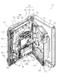
以下、遊技機の一種であるパチンコ遊技機(以下、「パチンコ機」という)の一実施の形態を、図面に基づいて詳細に説明する。図1はパチンコ機10の斜視図、図2及び図3はパチンコ機10の主要な構成を展開して示す斜視図、図4はパチンコ機10の背面図である。なお、図2では便宜上パチンコ機10の遊技領域内の構成を省略している。   Hereinafter, an embodiment of a pachinko gaming machine (hereinafter referred to as “pachinko machine”), which is a type of gaming machine, will be described in detail with reference to the drawings. FIG. 1 is a perspective view of the pachinko machine 10, FIGS. 2 and 3 are perspective views showing the main configuration of the pachinko machine 10 in an expanded state, and FIG. 4 is a rear view of the pachinko machine 10. In FIG. 2, the configuration in the game area of the pachinko machine 10 is omitted for convenience.

パチンコ機10は、当該パチンコ機10の外殻を形成する外枠11と、この外枠11に対して前方に回動可能に取り付けられた遊技機主部21とを有する。   The pachinko machine 10 includes an outer frame 11 that forms an outer shell of the pachinko machine 10, and a gaming machine main portion 21 that is attached to the outer frame 11 so as to be rotatable forward.

外枠11は、板材12〜15を四辺に連結し構成されるものであって矩形枠状をなしている。外枠11を構成する板材12〜15は、左右の板材12,13がアルミなどの金属製となっており、上下の板材14,15が木製となっている。パチンコ機10は、外枠11の上下の板材14,15を島設備に取り付け固定することにより、遊技ホールに設置される。上記のように左右の板材12,13を金属製とするとともに上下の板材14,15を木製とすることで、島設備への固定を可能としつつ外枠11の補強を行うことができる。なお、外枠11の構成は上記のものに限定されることはなく、全ての板材12〜15を木製としてもよく、全ての板材12〜15を金属製としてもよい。また、板材12〜15の全部又は一部を合成樹脂製としてもよい。また、パチンコ機10が外枠11を備える構成としたが、パチンコ機10は外枠11を備えずに遊技機主部21のみを備える構成としてもよい。   The outer frame 11 is configured by connecting plate members 12 to 15 to four sides and has a rectangular frame shape. In the plate members 12 to 15 constituting the outer frame 11, the left and right plate members 12, 13 are made of metal such as aluminum, and the upper and lower plate members 14, 15 are made of wood. The pachinko machine 10 is installed in the game hall by attaching and fixing the upper and lower plate members 14 and 15 of the outer frame 11 to the island facility. As described above, the left and right plate members 12, 13 are made of metal, and the upper and lower plate members 14, 15 are made of wood, so that the outer frame 11 can be reinforced while being fixed to the island facility. The configuration of the outer frame 11 is not limited to the above, and all the plate members 12 to 15 may be made of wood, and all the plate members 12 to 15 may be made of metal. Further, all or part of the plate materials 12 to 15 may be made of synthetic resin. Moreover, although the pachinko machine 10 is configured to include the outer frame 11, the pachinko machine 10 may be configured to include only the gaming machine main portion 21 without including the outer frame 11.

外枠11の左側の板材12には、その上下の各端部に支持金具17,18が取り付けられている。これら支持金具17,18に支持させるようにして、図2及び図3に示すように、遊技機主部21が外枠11に対して回動可能に取り付けられている。   Support metal fittings 17 and 18 are attached to the upper and lower ends of the left plate 12 of the outer frame 11. As shown in FIGS. 2 and 3, the gaming machine main part 21 is rotatably attached to the outer frame 11 so as to be supported by these support fittings 17 and 18.

遊技機主部21は、遊技機ベースユニット(本体枠又は内枠)22と、その遊技機ベースユニット22の前方に配置される遊技機前面ユニット(前面扉又は前枠)23と、遊技機ベースユニット22の後方に配置される裏パックユニット24とを備えている。遊技機主部21のうち遊技機ベースユニット22が外枠11に対して回動可能に支持されている。詳細には、正面視で左側を回動基端(開閉基端)側とし右側を回動先端(開閉先端)側として遊技機ベースユニット22が前方へ回動可能(開閉可能)とされている。   The gaming machine main unit 21 includes a gaming machine base unit (main body frame or inner frame) 22, a gaming machine front unit (front door or front frame) 23 disposed in front of the gaming machine base unit 22, and a gaming machine base. And a back pack unit 24 disposed behind the unit 22. A gaming machine base unit 22 of the gaming machine main portion 21 is supported so as to be rotatable with respect to the outer frame 11. More specifically, the gaming machine base unit 22 is turnable (openable / closable) forward, with the left side as the rotation base end (opening / closing base end) side and the right side as the rotation tip (opening / closing tip) side in front view. .

遊技機ベースユニット22は、図2及び図3に示すように、外枠11の開口全体を覆う大きさを有しており、その背面側であって回動先端側には施錠装置31が取り付けられている。施錠装置31は長尺状の連動杆32を備えており、当該連動杆32には上下一対の鉤金具33が設けられている。外枠11に対して遊技機ベースユニット22を閉鎖した際には、鉤金具33が外枠11の右側の板材13に設けられた受け金具34に係止され、施錠装置31により施錠状態とされるようになっている。また、遊技機ベースユニット22にはシリンダ錠35が設けられており、シリンダ錠35の操作によって連動杆32を上方向又は下方向のうち予め定められた方向に移動させると、外枠11に対する遊技機ベースユニット22の施錠状態が解除される。   As shown in FIGS. 2 and 3, the gaming machine base unit 22 has a size that covers the entire opening of the outer frame 11, and a locking device 31 is attached to the rear end side of the gaming machine base unit 22 at the rotating tip side. It has been. The locking device 31 is provided with a long interlocking rod 32, and the interlocking rod 32 is provided with a pair of upper and lower metal fittings 33. When the gaming machine base unit 22 is closed with respect to the outer frame 11, the bar bracket 33 is locked to the receiving bracket 34 provided on the plate 13 on the right side of the outer frame 11 and is locked by the locking device 31. It has become so. Further, the gaming machine base unit 22 is provided with a cylinder lock 35, and when the interlocking rod 32 is moved in a predetermined direction among the upward direction and the downward direction by the operation of the cylinder lock 35, a game with respect to the outer frame 11 is performed. The locked state of the machine base unit 22 is released.

遊技機ベースユニット22には、図2に示すように、遊技機前面ユニット23が回動可能に支持されており、正面視で左側を回動基端(開閉基端)側とし右側を回動先端(開閉先端)側として前方へ回動可能(開閉可能)とされている。また、遊技機ベースユニット22には、図3に示すように、裏パックユニット24が回動可能に支持されており、正面視で左側を回動基端(開閉基端)側とし右側を回動先端(開閉先端)側として後方へ回動可能(開閉可能)とされている。   As shown in FIG. 2, the gaming machine front unit 23 is rotatably supported by the gaming machine base unit 22. In the front view, the left side is the rotation base end (opening / closing base end) side, and the right side is rotated. It can be turned forward (openable and closable) as the tip (opening / closing tip) side. Further, as shown in FIG. 3, a backpack unit 24 is rotatably supported by the gaming machine base unit 22, and in the front view, the left side is the rotation base end (opening / closing base end) side and the right side is rotated. The moving tip (opening / closing tip) side can be rotated backward (openable / closable).

次に、遊技機ベースユニット22、遊技機前面ユニット23及び裏パックユニット24のそれぞれについて詳細に説明する。   Next, each of the gaming machine base unit 22, the gaming machine front unit 23, and the back pack unit 24 will be described in detail.

<遊技機ベースユニット22>
先ず、遊技機ベースユニット22の構成について詳細に説明する。図5は遊技機ベースユニット22の正面図、図6は遊技機ベースユニット22に搭載された遊技盤61の正面図、図7は遊技機ベースユニット22の背面図である。なお、図5では便宜上パチンコ機10の遊技領域内の構成を省略している。
<Game machine base unit 22>
First, the configuration of the gaming machine base unit 22 will be described in detail. FIG. 5 is a front view of the gaming machine base unit 22, FIG. 6 is a front view of the gaming board 61 mounted on the gaming machine base unit 22, and FIG. 7 is a rear view of the gaming machine base unit 22. In FIG. 5, the configuration in the game area of the pachinko machine 10 is omitted for convenience.

遊技機ベースユニット22は、外形が外枠11とほぼ同一形状をなす樹脂ベース41を主体に構成されている。樹脂ベース41の中央部には略楕円形状の窓孔51が形成されている。樹脂ベース41にはその後方から遊技盤61が着脱可能に取り付けられている。詳細には、樹脂ベース41の裏面には、図7に示すように、複数(本実施の形態では4箇所)の固定金具52〜55が設けられており、これら固定金具52〜55によって遊技盤61は後方へ脱落しないように固定されている。固定金具52〜55は手動で回動操作することができ、固定位置(ロック位置)と固定解除位置(アンロック位置)とに切り換えることができるよう構成されている。   The gaming machine base unit 22 is mainly composed of a resin base 41 whose outer shape is substantially the same as that of the outer frame 11. A substantially elliptical window hole 51 is formed at the center of the resin base 41. A game board 61 is detachably attached to the resin base 41 from behind. Specifically, as shown in FIG. 7, a plurality of (four places in the present embodiment) fixing brackets 52 to 55 are provided on the back surface of the resin base 41. 61 is fixed so as not to fall backward. The fixing brackets 52 to 55 can be manually rotated, and can be switched between a fixing position (lock position) and a fixing release position (unlock position).

遊技盤61は合板よりなり、遊技盤61の前面に形成された遊技領域が樹脂ベース41の窓孔51を通じて遊技機ベースユニット22の前面側に露出した状態となっている。   The game board 61 is made of plywood, and the game area formed on the front surface of the game board 61 is exposed to the front surface side of the gaming machine base unit 22 through the window hole 51 of the resin base 41.

ここで、遊技盤61の構成を図6に基づいて説明する。遊技盤61には、ルータ加工が施されることによって前後方向に貫通する大小複数の開口部が形成されている。各開口部には一般入賞口62,可変入賞装置63,上作動口64,下作動口65,スルーゲート66及び可変表示ユニット67等がそれぞれ設けられている。このうち、可変入賞装置63、上作動口64、下作動口65及び可変表示ユニット67は、遊技盤61の左右方向の中央において上下方向に並べて設けられており、上から可変表示ユニット67、上作動口64、下作動口65及び可変入賞装置63の順となっている。また、一般入賞口62は、遊技盤61の下部において、左側に2個及び右側に2個の合計4個設けられている。ちなみに、遊技盤61の左側は遊技機前面ユニット23の回動基端側に相当し、遊技盤61の右側は遊技機前面ユニット23の回動先端側に相当する。   Here, the structure of the game board 61 is demonstrated based on FIG. The game board 61 has a plurality of large and small openings penetrating in the front-rear direction by being subjected to router processing. Each opening is provided with a general winning port 62, a variable winning device 63, an upper operating port 64, a lower operating port 65, a through gate 66, a variable display unit 67, and the like. Among these, the variable winning device 63, the upper operation port 64, the lower operation port 65, and the variable display unit 67 are provided side by side in the vertical direction at the center of the game board 61 in the left-right direction. The operation port 64, the lower operation port 65, and the variable winning device 63 are arranged in this order. Further, in the lower part of the game board 61, four general winning ports 62 are provided, two on the left side and two on the right side. Incidentally, the left side of the gaming board 61 corresponds to the rotating base end side of the gaming machine front unit 23, and the right side of the gaming board 61 corresponds to the rotating distal end side of the gaming machine front unit 23.

一般入賞口62、可変入賞装置63、上作動口64及び下作動口65に遊技球が入球すると、それが検知スイッチにより検知され、その検知結果に基づいて所定数の賞球の払い出しが実行される。具体的には、一般入賞口62に一の遊技球が入球すると単位遊技球数として10個の遊技球が払い出され、可変入賞装置63に一の遊技球が入球すると単位遊技球数として15個の遊技球が払い出され、上作動口64に一の遊技球が入球すると単位遊技球数として3個の遊技球が払い出され、下作動口65に一の遊技球が入球すると単位遊技球数として4個の遊技球が払い出される。   When a game ball enters the general winning port 62, the variable winning device 63, the upper operating port 64, and the lower operating port 65, it is detected by a detection switch, and a predetermined number of winning balls are paid out based on the detection result. Is done. Specifically, when one game ball enters the general prize opening 62, 10 game balls are paid out as the number of unit game balls, and when one game ball enters the variable winning device 63, the number of unit game balls 15 game balls are paid out, and when one game ball enters the upper operation port 64, 3 game balls are paid out as the number of unit game balls, and one game ball enters the lower operation port 65. When a ball is played, four game balls are paid out as the number of unit game balls.

その他に、遊技盤61の最下部にはアウト口68が設けられており、各種入賞口等に入らなかった遊技球はアウト口68を通って遊技領域から排出される。また、遊技盤61には、遊技球の落下方向を適宜分散、調整等するために多数の釘69が植設されていると共に、風車等の各種部材(役物)が配設されている。   In addition, an out port 68 is provided at the lowermost part of the game board 61, and game balls that have not entered various winning ports etc. are discharged from the game area through the out port 68. The game board 61 is provided with a large number of nails 69 for dispersing and adjusting the falling direction of the game ball as appropriate, and various members (functions) such as a windmill.

可変表示ユニット67には、いずれかの作動口64,65への入賞をトリガとして図柄を可変表示する図柄表示装置71が設けられている。また、可変表示ユニット67には、図柄表示装置71を囲むようにしてセンターフレーム72が配設されている。センターフレーム72の上部には、第1特定ランプ部73及び第2特定ランプ部74が設けられている。また、センターフレーム72の上部及び下部にはそれぞれ保留ランプ部75,76が設けられている。下側の保留ランプ部75は、図柄表示装置71及び第1特定ランプ部73に対応しており、遊技球が作動口64,65を通過した回数は最大4回まで保留され保留ランプ部75の点灯によってその保留個数が表示されるようになっている。上側の保留ランプ部76は、第2特定ランプ部74に対応しており、遊技球がスルーゲート66を通過した回数は最大4回まで保留され保留ランプ部76の点灯によってその保留個数が表示されるようになっている。   The variable display unit 67 is provided with a symbol display device 71 for variably displaying symbols with a winning at one of the operation ports 64 and 65 as a trigger. The variable display unit 67 is provided with a center frame 72 so as to surround the symbol display device 71. A first specific lamp portion 73 and a second specific lamp portion 74 are provided on the center frame 72. Reservation lamp portions 75 and 76 are provided at the upper and lower portions of the center frame 72, respectively. The lower holding lamp unit 75 corresponds to the symbol display device 71 and the first specific lamp unit 73, and the number of times that the game ball has passed through the operation ports 64 and 65 is held up to four times, and the holding lamp unit 75 The number of hold is displayed by lighting. The upper holding lamp unit 76 corresponds to the second specific lamp unit 74, and the number of times that the game ball has passed through the through gate 66 is held up to four times, and the number of the holding balls is displayed by turning on the holding lamp unit 76. It has become so.

図柄表示装置71は、液晶ディスプレイを備えた液晶表示装置として構成されており、後述する表示制御装置により表示内容が制御される。図柄表示装置71には、例えば左、中及び右に並べて図柄が表示され、これらの図柄が上下方向にスクロールされるようにして変動表示されるようになっている。そして、予め設定されている有効ライン上に所定の組合せの図柄が停止表示された場合には、特別遊技状態(以下、大当たりという)が発生することとなる。なお、図柄表示装置71は、CRT,ドットマトリックス,7セグメント等その他のタイプにより表示画面を構成したものであってもよい。   The symbol display device 71 is configured as a liquid crystal display device including a liquid crystal display, and display contents are controlled by a display control device described later. In the symbol display device 71, for example, symbols are displayed side by side on the left, middle, and right, and these symbols are variably displayed as they are scrolled up and down. When a predetermined combination of symbols is stopped and displayed on a preset active line, a special gaming state (hereinafter referred to as a jackpot) occurs. The symbol display device 71 may have a display screen made up of other types such as CRT, dot matrix, and 7 segments.

第1特定ランプ部73では、作動口64への入賞をトリガとして所定の順序で発光色の切り替えが行われ、予め定められた色で停止表示された場合には大当たりが発生する。また、第2特定ランプ部74では、遊技球のスルーゲート66の通過をトリガとして所定の順序で発光色の切り替えが行われ、予め定められた色で停止表示された場合には下作動口65に付随する電動役物65aが所定時間だけ開放状態となる。   In the first specific lamp unit 73, the emission color is switched in a predetermined order using a winning at the operation port 64 as a trigger, and if the display is stopped in a predetermined color, a big hit occurs. Further, in the second specific lamp portion 74, the emission color is switched in a predetermined order triggered by the passage of the game ball through the through gate 66, and when the stop color is displayed in a predetermined color, the lower operation port 65 is displayed. The electric accessory 65a attached to is opened for a predetermined time.

ちなみに、下作動口65は、開閉手段としての電動役物65aが開放状態の場合に入球が可能となり、閉鎖状態の場合に入球が不可となる。なお、これに限定されることはなく、電動役物65aが開放状態の場合に入球し易くなり、閉鎖状態の場合に入球しがたくなる構成としてもよい。   Incidentally, the lower operating port 65 can enter when the electric accessory 65a serving as the opening / closing means is in an open state, and cannot enter when it is in a closed state. Note that the present invention is not limited to this, and a configuration may be adopted in which it is easy to enter when the electric utility item 65a is in an open state and it is difficult to enter when the electric accessory 65a is in a closed state.

可変入賞装置63は、開閉手段としての開閉扉63aが通常は遊技球が入球できない又は入球しがたい閉鎖状態になっており、大当たりの際に遊技球が入球しやすい所定の開放状態に切り換えられるようになっている。可変入賞装置63の開放態様としては、所定時間(例えば30秒間)の経過又は所定個数(例えば10個)の入賞を1ラウンドとして、複数ラウンド(例えば15ラウンド)を上限として可変入賞装置63が繰り返し開放されるものが一般的である。   In the variable winning device 63, the open / close door 63a as an opening / closing means is normally in a closed state in which a game ball cannot enter or is difficult to enter, and a predetermined open state in which a game ball can easily enter in the case of a big hit Can be switched to. As an opening mode of the variable winning device 63, the variable winning device 63 is repeated with a predetermined time (for example, 30 seconds) or a predetermined number (for example, 10) of winnings as one round and a plurality of rounds (for example, 15 rounds) as an upper limit. What is opened is common.

遊技盤61には、内レール部77と外レール部78とが取り付けられており、これら内レール部77と外レール部78とにより誘導レールが構成され、遊技球発射機構から発射された遊技球が遊技領域の上部に案内されるようになっている。ちなみに、図5に示すように、樹脂ベース41の窓孔51の右上部には返しゴム79が設けられており、所定以上の勢いで発射された遊技球は返しゴム79に当たり、遊技領域の中央寄りに跳ね返されるようになっている。この場合、返しゴム79はその遊技球が当たる面が遊技領域の中央側に向けて傾斜させて形成されているため、遊技領域の中央に向けた遊技球の跳ね返しが良好に行われるようになっている。   An inner rail portion 77 and an outer rail portion 78 are attached to the game board 61, and a guide rail is constituted by the inner rail portion 77 and the outer rail portion 78, and a game ball launched from the game ball launching mechanism. Is guided to the upper part of the game area. Incidentally, as shown in FIG. 5, a return rubber 79 is provided at the upper right portion of the window hole 51 of the resin base 41, and a game ball launched at a predetermined momentum or more hits the return rubber 79, and is in the center of the game area. It is designed to be bounced back. In this case, the return rubber 79 is formed so that the surface on which the game ball hits is inclined toward the center of the game area, so that the game ball is rebounded toward the center of the game area. ing.

遊技球発射機構80は、図5に示すように、樹脂ベース41における窓孔51の下方に取り付けられている。遊技球発射機構80は、電磁式のソレノイド81と、発射レール82と、球送り機構83とからなり、ソレノイド81への電気的な信号の入力により当該ソレノイド81の出力軸が伸縮方向に移動し、球送り機構83によって発射レール82上に置かれた遊技球を遊技領域に向けて打ち出す。ソレノイド81への電気的な信号の入力は、遊技機前面ユニット23の下部に設けられた遊技球発射ハンドル84(図1等参照)が操作されることに基づいて発生する。   The game ball launching mechanism 80 is attached below the window hole 51 in the resin base 41 as shown in FIG. The game ball launching mechanism 80 includes an electromagnetic solenoid 81, a launching rail 82, and a ball feed mechanism 83, and the output shaft of the solenoid 81 moves in the expansion / contraction direction by the input of an electrical signal to the solenoid 81. Then, the game ball placed on the launch rail 82 is launched by the ball feed mechanism 83 toward the game area. The input of an electrical signal to the solenoid 81 is generated based on the operation of a game ball launch handle 84 (see FIG. 1 and the like) provided at the lower portion of the gaming machine front unit 23.

樹脂ベース41の前面における回動基端側にはその上端部及び下端部に支持金具42,43が取り付けられており、これら支持金具42,43に対して遊技機前面ユニット23が支持されていることで当該遊技機前面ユニット23が遊技機ベースユニット22に対して前方に回動可能となっている。また、樹脂ベース41の前面における回動先端側には、遊技機前面ユニット23の背面に設けられた鉤金具44(図2参照)を挿入するための挿入孔45が上下方向に離間させて複数設けられている。遊技機ベースユニット22に対して遊技機前面ユニット23を閉鎖した状態では、遊技機前面ユニット23の鉤金具44が挿入孔45内に入り込み、当該鉤金具44は上述した施錠装置31に係止される。これにより、遊技機ベースユニット22に対して遊技機前面ユニット23が施錠された状態となる。この施錠状態はシリンダ錠35の操作によって施錠装置31の連動杆32を、外枠11に対する遊技機ベースユニット22の解錠を行う場合とは反対側に移動させることで解除される。   Support metal fittings 42 and 43 are attached to the upper and lower ends of the rotation base end side of the front surface of the resin base 41, and the gaming machine front unit 23 is supported by the support metal fittings 42 and 43. Thus, the gaming machine front unit 23 can be rotated forward with respect to the gaming machine base unit 22. Further, a plurality of insertion holes 45 are formed on the front side of the front surface of the resin base 41 so as to be inserted in the vertical direction in order to insert the metal fittings 44 (see FIG. 2) provided on the back surface of the gaming machine front unit 23. Is provided. In a state where the gaming machine front unit 23 is closed with respect to the gaming machine base unit 22, the metal fitting 44 of the gaming machine front unit 23 enters the insertion hole 45, and the metal fitting 44 is locked to the locking device 31 described above. The As a result, the gaming machine front unit 23 is locked to the gaming machine base unit 22. This locked state is released by moving the interlocking rod 32 of the locking device 31 to the opposite side to the case where the gaming machine base unit 22 is unlocked with respect to the outer frame 11 by operating the cylinder lock 35.

<遊技機前面ユニット23>
ここで、遊技機前面ユニット23の構成について説明する。図8は遊技機前面ユニット23の背面図である。
<Game machine front unit 23>
Here, the configuration of the gaming machine front unit 23 will be described. FIG. 8 is a rear view of the gaming machine front unit 23.

遊技機前面ユニット23は遊技機ベースユニット22の前面側全体を覆うようにして設けられている。遊技機前面ユニット23には、図1に示すように、上記遊技領域のほぼ全域を前方から視認することができるようにした略楕円形状の窓パネル部91が設けられている。窓パネル部91の周囲には、各種ランプ等の発光手段が設けられている。例えば、窓パネル部91の周縁に沿ってLED等の発光手段を内蔵した環状電飾部92が設けられている。環状電飾部92では、大当たり時や所定のリーチ時等における遊技状態の変化に応じて点灯や点滅が行われる。また、環状電飾部92の中央であってパチンコ機10の最上部には所定のエラー時に点灯するエラー表示ランプ部93が設けられている。また、窓パネル部91の左上方及び右上方には、遊技状態に応じた効果音などが出力されるスピーカ部94が設けられている。   The gaming machine front unit 23 is provided so as to cover the entire front side of the gaming machine base unit 22. As shown in FIG. 1, the gaming machine front unit 23 is provided with a substantially elliptical window panel portion 91 that allows almost the entire gaming area to be viewed from the front. Around the window panel portion 91, light emitting means such as various lamps are provided. For example, an annular illumination part 92 containing a light emitting means such as an LED is provided along the periphery of the window panel part 91. In the annular illumination part 92, lighting or blinking is performed according to a change in the gaming state at the time of a big hit or a predetermined reach. In addition, an error display lamp portion 93 that is turned on at the time of a predetermined error is provided at the center of the annular illumination portion 92 and at the top of the pachinko machine 10. In addition, on the upper left and upper right of the window panel unit 91, a speaker unit 94 that outputs sound effects according to the gaming state is provided.

遊技機前面ユニット23における窓パネル部91の下方には、手前側へ膨出した上側膨出部95と下側膨出部96とが上下に並設されている。上側膨出部95内側には上方に開口した上皿95aが設けられており、下側膨出部96内側には同じく上方に開口した下皿96aが設けられている。上皿95aは、後述する払出装置より払い出された遊技球を一旦貯留し、一列に整列させながら後述する遊技球発射機構側へ導くための機能を有する。また、下皿96aは、上皿95a内にて余剰となった遊技球を貯留する機能を有する。なお、下側膨出部96の右方には、上述した遊技球発射ハンドル84が設けられている。   Below the window panel portion 91 in the gaming machine front unit 23, an upper bulging portion 95 and a lower bulging portion 96 that bulge to the near side are arranged in parallel. An upper plate 95a that opens upward is provided inside the upper bulge portion 95, and a lower plate 96a that is also opened upward is provided inside the lower bulge portion 96. The upper plate 95a has a function of temporarily storing game balls paid out from a payout device described later and guiding them to the game ball launching mechanism described later while aligning them in a line. In addition, the lower tray 96a has a function of storing game balls that are surplus in the upper tray 95a. Note that the game ball launching handle 84 described above is provided to the right of the lower bulging portion 96.

遊技機前面ユニット23の背面における回動基端側(図8の右側)には、その上端部及び下端部に突起軸97,98が設けられている。これら突起軸97,98は遊技機ベースユニット22に対する組付機構を構成する。また、遊技機前面ユニット23の背面における回動先端側(図8の左側)には、上述した鉤金具44が上下方向に複数並設されている。   Protrusion shafts 97 and 98 are provided on the upper and lower ends of the rotation base end side (the right side in FIG. 8) on the back of the gaming machine front unit 23. These projecting shafts 97 and 98 constitute an assembly mechanism for the gaming machine base unit 22. In addition, a plurality of the above-mentioned metal fittings 44 are arranged in the vertical direction on the rotating front end side (the left side in FIG. 8) on the back surface of the gaming machine front unit 23.

また、遊技機前面ユニット23の背面には、図8に示すように、前面側通路ユニット271が取り付けられている。前面側通路ユニット271は、合成樹脂により成形されており、上皿95aに通じる前扉側上皿通路と、下皿96aに通じる前扉側下皿通路とが形成されている。前面側通路ユニット271の詳細については後に説明する。   Further, as shown in FIG. 8, a front side passage unit 271 is attached to the back of the gaming machine front unit 23. The front side passage unit 271 is formed of a synthetic resin, and includes a front door side upper plate passage that communicates with the upper plate 95a and a front door side lower plate passage that communicates with the lower plate 96a. Details of the front-side passage unit 271 will be described later.

<遊技機ベースユニット22の背面構成>
次に、遊技機ベースユニット22の背面構成について図7を用いて詳細に説明する。
<Back side configuration of the gaming machine base unit 22>
Next, the back configuration of the gaming machine base unit 22 will be described in detail with reference to FIG.

樹脂ベース41の背面における回動先端側には既に説明した施錠装置31が設けられている。また、樹脂ベース41の中央には上記のとおり遊技盤61が取り付けられている。   The locking device 31 already described is provided on the rotation tip side of the back surface of the resin base 41. Further, the game board 61 is attached to the center of the resin base 41 as described above.

遊技盤61の中央に配置された可変表示ユニット67には、図3及び図7に示すように、センターフレーム72を後方から覆う合成樹脂製のフレームカバー100が後方に突出させて設けられており、フレームカバー100に対して後側から上述した図柄表示装置71が取り付けられているとともに、その図柄表示装置71を駆動するための表示制御装置101が取り付けられている。これら図柄表示装置71及び表示制御装置101は前後方向に重ねて配置され(図柄表示装置71が前、表示制御装置101が後)、さらにその後方に音声ランプ制御装置ユニット102が搭載されている。音声ランプ制御装置ユニット102は、音声ランプ制御装置103と、取付台104とを具備する構成となっており、取付台104上に音声ランプ制御装置103が装着されている。   As shown in FIGS. 3 and 7, the variable display unit 67 disposed at the center of the game board 61 is provided with a frame cover 100 made of synthetic resin that covers the center frame 72 from the rear side so as to protrude rearward. The symbol display device 71 described above is attached to the frame cover 100 from the rear side, and a display control device 101 for driving the symbol display device 71 is attached. The symbol display device 71 and the display control device 101 are overlapped in the front-rear direction (the symbol display device 71 is the front and the display control device 101 is the rear), and the sound lamp control device unit 102 is mounted on the rear side. The sound lamp control device unit 102 includes a sound lamp control device 103 and a mounting base 104, and the sound lamp control device 103 is mounted on the mounting base 104.

音声ランプ制御装置103は、後述する主制御装置からの指示に従い音声やランプ表示、及び表示制御装置の制御を司る音声ランプ制御基板を具備しており、音声ランプ制御基板が透明樹脂材料等よりなる基板ボックスに収容されて構成されている。   The sound lamp control device 103 includes a sound lamp control board that controls sound and lamp display and control of the display control device in accordance with instructions from a main control device described later, and the sound lamp control substrate is made of a transparent resin material or the like. It is housed and configured in a substrate box.

遊技盤61の背面であって可変表示ユニット67の下方には、主制御装置ユニット105が搭載されている。主制御装置ユニット105は、合成樹脂製の取付台106を有し、取付台106に主制御装置107が搭載されている。主制御装置107は、遊技の主たる制御を司る機能(主制御回路)と、電源を監視する機能(停電監視回路)とを有する主制御基板を具備しており、当該主制御基板が透明樹脂材料等よりなる基板ボックス108に収容されて構成されている。なお、当該基板ボックス108には、当該基板ボックスの開放痕跡手段としてカシメ構造や図示しない封印シールが設けられているとともに、取付台106に対する主制御装置107の離脱痕跡手段としてカシメ構造が設けられている。   A main controller unit 105 is mounted on the back of the game board 61 and below the variable display unit 67. The main control unit 105 has a synthetic resin mounting base 106, and a main control apparatus 107 is mounted on the mounting base 106. The main control device 107 includes a main control board having a function (main control circuit) that governs the main control of the game and a function (power failure monitoring circuit) that monitors the power supply, and the main control board is a transparent resin material. It is configured to be accommodated in a substrate box 108 made of, for example. The board box 108 is provided with a caulking structure or a sealing seal (not shown) as an opening trace means of the board box, and a caulking structure as a leaving trace means of the main controller 107 with respect to the mounting base 106. Yes.

遊技盤61の背面における主制御装置ユニット105により覆われた領域には、図示しない集合板ユニットが設けられている。集合板ユニットには、各種入賞口に入賞した遊技球を回収するための遊技球回収機構や、各種入賞口等への遊技球の入賞を検知するための入賞検知センサなどが設けられている。遊技球回収機構にて回収された遊技球は後述する排出通路を介してパチンコ機10外部に排出される。また、入賞検知センサは主制御装置107と電気的に接続されており、遊技球の入賞を検知した場合の検知信号は主制御装置107にて入力される。   A collective plate unit (not shown) is provided in an area covered by the main controller unit 105 on the back surface of the game board 61. The collective board unit is provided with a game ball collecting mechanism for collecting game balls won in various winning ports, a winning detection sensor for detecting winning of game balls in various winning ports, and the like. The game balls collected by the game ball collection mechanism are discharged to the outside of the pachinko machine 10 through a discharge passage described later. The winning detection sensor is electrically connected to the main controller 107, and a detection signal when a winning of a game ball is detected is input by the main controller 107.

樹脂ベース41の背面における回動基端側(図7の右側)には、軸受け金具111,112,113が取り付けられている。軸受け金具111〜113は上下に離間させて3個設けられている。なお、軸受け金具111〜113の数は任意であり、2個であってもよく、4個以上であってもよい。これら軸受け金具111〜113に対して軸支させて遊技機ベースユニット22には裏パックユニット24が取り付けられている。裏パックユニット24により、図5に示すように、可変表示ユニット67の全部及び主制御装置ユニット105の一部が後方から覆われており、裏パックユニット24を開放させない限り可変表示ユニット67及び主制御装置ユニット105を樹脂ベース41から取り外すことができないようになっている。   Bearing fittings 111, 112, and 113 are attached to the rotation base end side (the right side in FIG. 7) on the back surface of the resin base 41. Three bearing fittings 111 to 113 are provided apart from each other in the vertical direction. The number of bearing fittings 111 to 113 is arbitrary, and may be two or may be four or more. A backpack unit 24 is attached to the gaming machine base unit 22 while being pivotally supported with respect to the bearing fittings 111 to 113. As shown in FIG. 5, the back pack unit 24 covers all of the variable display unit 67 and a part of the main controller unit 105 from the rear. Unless the back pack unit 24 is opened, the variable display unit 67 and the main controller unit 105 are covered. The control device unit 105 cannot be removed from the resin base 41.

樹脂ベース41の背面には、図3及び図7に示すように、裏パックユニット24を遊技機ベースユニット22に固定するための固定金具115が設けられている。固定金具115は手動で回動操作することができ、固定位置(ロック位置)と固定解除位置(アンロック位置)とに切り換えることができるよう構成されている。また、図7に示すように、樹脂ベース41の背面には締結孔部116が形成されており、当該締結孔部116に対して裏パックユニット24に設けられた締結具117(図9参照)を締結させることによっても裏パックユニット24が遊技機ベースユニット22に固定される。   As shown in FIGS. 3 and 7, a fixing metal 115 for fixing the back pack unit 24 to the gaming machine base unit 22 is provided on the back surface of the resin base 41. The fixing bracket 115 can be manually rotated, and can be switched between a fixing position (lock position) and a fixing release position (unlock position). Further, as shown in FIG. 7, a fastening hole 116 is formed on the back surface of the resin base 41, and a fastener 117 (see FIG. 9) provided in the back pack unit 24 with respect to the fastening hole 116. Also, the back pack unit 24 is fixed to the gaming machine base unit 22 by fastening.

<裏パックユニット24>
次に、裏パックユニット24の構成について詳細に説明する。図9は裏パックユニット24の正面図、図10は裏パックユニット24の分解斜視図である。
<Back pack unit 24>
Next, the configuration of the back pack unit 24 will be described in detail. 9 is a front view of the back pack unit 24, and FIG. 10 is an exploded perspective view of the back pack unit 24.

裏パックユニット24は、当該裏パックユニット24の上部及び中央部分を構成する第1裏パックユニット121と、当該第1裏パックユニット121に連続させて設けられ裏パックユニット24の下部を構成する第2裏パックユニット141とを備えている。第1裏パックユニット121にはその下部に開口部122が形成されており、第2裏パックユニット141の上部は当該開口部122の下縁部分を構成している。   The back pack unit 24 includes a first back pack unit 121 that constitutes an upper portion and a central portion of the back pack unit 24, and a first portion that is provided continuously with the first back pack unit 121 and constitutes a lower portion of the back pack unit 24. 2 back pack unit 141. An opening 122 is formed in the lower portion of the first back pack unit 121, and the upper portion of the second back pack unit 141 constitutes the lower edge portion of the opening 122.

第1裏パックユニット121と第2裏パックユニット141には、図9に示すように、それぞれ軸金具123,139が設けられており、それら軸金具123,139はそれぞれ個別に軸受け金具111〜113に支持されている。これにより、第1裏パックユニット121と第2裏パックユニット141とは、遊技機ベースユニット22に対してそれぞれ個別に回動可能となっている。   As shown in FIG. 9, the first back pack unit 121 and the second back pack unit 141 are respectively provided with shaft fittings 123 and 139. The shaft fittings 123 and 139 are individually provided with bearing fittings 111 to 113, respectively. It is supported by. Accordingly, the first back pack unit 121 and the second back pack unit 141 can be individually rotated with respect to the gaming machine base unit 22.

ここで、上記のとおり、第2裏パックユニット141はその上部が第1裏パックユニット121の開口部122の下縁部分を構成しており、当該下縁部分において、第1裏パックユニット121がパチンコ機10前方となるようにして第1裏パックユニット121と第2裏パックユニット141とが前後に重なっている。したがって、第1裏パックユニット121を遊技機ベースユニット22に対して閉鎖した状態で第2裏パックユニット141を開放させることはできるが、第2裏パックユニット141を閉鎖した状態で第1裏パックユニット121を開放させることはできない。なお、これに限定されることはなく、開閉の関係が第1裏パックユニット121と第2裏パックユニット141とで逆であってもよく、第1裏パックユニット121と第2裏パックユニット141とが相互に干渉することなく開閉可能な構成であってもよい。さらには、第1裏パックユニット121と第2裏パックユニット141とが一体化され個別に開閉できない構成としてもよい。   Here, as described above, the upper portion of the second back pack unit 141 constitutes the lower edge portion of the opening 122 of the first back pack unit 121, and the first back pack unit 121 is formed at the lower edge portion. The first back pack unit 121 and the second back pack unit 141 overlap each other so as to be in front of the pachinko machine 10. Therefore, the second back pack unit 141 can be opened with the first back pack unit 121 closed with respect to the gaming machine base unit 22, but the first back pack unit 141 can be opened with the second back pack unit 141 closed. The unit 121 cannot be opened. The opening / closing relationship may be reversed between the first back pack unit 121 and the second back pack unit 141, and the first back pack unit 121 and the second back pack unit 141 may be reversed. And can be opened and closed without interfering with each other. Further, the first back pack unit 121 and the second back pack unit 141 may be integrated and cannot be individually opened and closed.

次に、第1裏パックユニット121の構成について詳細に説明する。   Next, the configuration of the first back pack unit 121 will be described in detail.

第1裏パックユニット121は、裏パック124を備えており、当該裏パック124に対して、払出機構部125が取り付けられている。裏パック124は透明性を有する合成樹脂により成形されており、払出機構部125などが取り付けられるベース部126と、パチンコ機10後方に突出し略直方体形状をなす保護カバー部127とを有する。保護カバー部127は左右側面及び上面が閉鎖され且つ下面のみが開放された形状をなし、少なくとも可変表示ユニット67を囲むのに十分な大きさを有する。   The first back pack unit 121 includes a back pack 124, and a payout mechanism 125 is attached to the back pack 124. The back pack 124 is formed of a synthetic resin having transparency, and includes a base portion 126 to which the payout mechanism portion 125 and the like are attached, and a protective cover portion 127 that protrudes rearward from the pachinko machine 10 and has a substantially rectangular parallelepiped shape. The protective cover 127 has a shape in which the left and right side surfaces and the upper surface are closed and only the lower surface is opened, and has a size sufficient to surround at least the variable display unit 67.

ベース部126には、その右上部に外部端子板131が設けられている。外部端子板131には各種の出力端子が設けられており、これらの出力端子を通じて遊技ホール側の管理制御装置に対して各種信号が出力される。また、ベース部126には上述した第1裏パックユニット121の軸金具123が設けられている。   The base part 126 is provided with an external terminal board 131 at the upper right part thereof. The external terminal board 131 is provided with various output terminals, and various signals are output to the management control device on the game hall side through these output terminals. Further, the base 126 is provided with the shaft fitting 123 of the first back pack unit 121 described above.

ベース部126には、保護カバー部127を迂回するようにして払出機構部125が配設されている。払出機構部125は、タンク132と、タンクレール133と、上下通路ユニット134とを備えている。タンク132は上方に開放されており、裏パック124の最上部に設けられている。タンク132には遊技ホールの島設備から遊技球が逐次補給される。タンクレール133は、タンク132の下方において当該タンク132に連結されており、下流側に向けて緩やかに傾斜している。当該タンクレール133の下流部に連結させて上下通路ユニット134が設けられている。上下通路ユニット134は上下方向に延びており、その途中位置に払出装置135が設けられている。また、上下通路ユニット134の下流側には、球受け部、裏パック側通路部、本体側通路部及び前面側通路部が設けられており、前面側通路部は上皿95a及び下皿96aに連通されている。   The base portion 126 is provided with a payout mechanism portion 125 so as to bypass the protective cover portion 127. The payout mechanism 125 includes a tank 132, a tank rail 133, and a vertical passage unit 134. The tank 132 is opened upward and is provided at the top of the back pack 124. The game balls are sequentially supplied to the tank 132 from the island facilities of the game hall. The tank rail 133 is connected to the tank 132 below the tank 132, and is gently inclined toward the downstream side. An upper and lower passage unit 134 is connected to the downstream portion of the tank rail 133. The vertical passage unit 134 extends in the vertical direction, and a dispensing device 135 is provided at a midway position thereof. Further, a ball receiving portion, a back pack side passage portion, a main body side passage portion and a front side passage portion are provided on the downstream side of the vertical passage unit 134, and the front side passage portions are provided on the upper plate 95a and the lower plate 96a. It is communicated.

つまり、タンク132と、上皿95a及び下皿96aの球受け皿との間には、タンクレール133、上下通路ユニット134、球受け部、裏パック側通路部、本体側通路部及び前面側通路部からなる誘導通路部が設けられており、タンク132に貯留されている遊技球は当該誘導通路部を通じて上皿95a又は下皿96aに払い出される。なお、上下通路ユニット134の構成、及びそれよりも下流側の構成については後に詳細に説明する。   That is, between the tank 132 and the ball trays of the upper plate 95a and the lower plate 96a, the tank rail 133, the vertical passage unit 134, the ball receiving portion, the back pack side passage portion, the main body side passage portion, and the front side passage portion. A guide passage portion is provided, and the game balls stored in the tank 132 are paid out to the upper plate 95a or the lower plate 96a through the guide passage portion. The configuration of the vertical passage unit 134 and the configuration on the downstream side thereof will be described in detail later.

払出機構部125には、裏パック基板136が設置されている。裏パック基板136には、例えば交流24ボルトの主電源が供給され、電源スイッチ137の切替操作により電源ON又は電源OFFとされるようになっている。   A backpack substrate 136 is installed in the dispensing mechanism unit 125. The back pack substrate 136 is supplied with, for example, a main power of 24 volts AC, and is turned on or off by a switching operation of the power switch 137.

次に、第2裏パックユニット141の構成について詳細に説明する。   Next, the configuration of the second back pack unit 141 will be described in detail.

第2裏パックユニット141は、排出通路盤142と制御装置集合ユニット143とを備えている。排出通路盤142は第2裏パックユニット141の前側を構成し、制御装置集合ユニット143は第2裏パックユニット141の後側を構成している。そして、これら排出通路盤142と制御装置集合ユニット143とが前後に組み付けられて第2裏パックユニット141が構成されている。   The second back pack unit 141 includes a discharge passage board 142 and a control device assembly unit 143. The discharge passage board 142 constitutes the front side of the second back pack unit 141, and the control device assembly unit 143 constitutes the rear side of the second back pack unit 141. The discharge passage board 142 and the controller assembly unit 143 are assembled in the front-rear direction to form a second back pack unit 141.

排出通路盤142は、制御装置集合ユニット143と対向する面に後方に開放された排出通路144が形成されており、当該排出通路144の開放部は制御装置集合ユニット143によって塞がれている。排出通路144は、遊技ホールの島設備等へ遊技球を排出するように形成されており、上述した各種入賞口等から排出通路144に導出された遊技球は当該排出通路144を通ることでパチンコ機10外部に排出される。   The discharge passage board 142 is formed with a discharge passage 144 opened rearward on a surface facing the control device assembly unit 143, and an open portion of the discharge passage 144 is closed by the control device assembly unit 143. The discharge passage 144 is formed so as to discharge the game balls to the island facilities of the game hall, and the game balls led out to the discharge passage 144 from the above-described various winning holes etc. pass through the discharge passage 144 to make a pachinko parlor. It is discharged outside the machine 10.

制御装置集合ユニット143は、横長形状をなす取付台145を有し、取付台145に払出制御装置146と電源及び発射制御装置147とが搭載されている。これら払出制御装置146と電源及び発射制御装置147とは、払出制御装置146がパチンコ機10後方となるように前後に重ねて配置されている。   The control device assembly unit 143 has a horizontally long mounting base 145, and a payout control device 146 and a power source and launch control device 147 are mounted on the mounting base 145. The payout control device 146 and the power supply / launch control device 147 are arranged so as to overlap each other so that the payout control device 146 is located behind the pachinko machine 10.

払出制御装置146は、基板ボックス148内に払出装置135を制御する払出制御基板が収容されている。なお、払出制御装置146から払出装置135への払出指令の信号は上述した裏パック基板136により中継される。また、払出制御装置146には状態復帰スイッチ148aが設けられている。例えば、払出装置135における球詰まり等、払出エラーの発生時において状態復帰スイッチ148aが押されると、球詰まりの解消が図られるようになっている。   The payout control device 146 contains a payout control board for controlling the payout device 135 in the board box 148. The payout command signal from the payout control device 146 to the payout device 135 is relayed by the backpack substrate 136 described above. The payout control device 146 is provided with a state return switch 148a. For example, when the state return switch 148a is pressed when a payout error occurs, such as a ball jam in the payout device 135, the ball jam is eliminated.

電源及び発射制御装置147は、基板ボックス149内に電源及び発射制御基板が収容されており、当該基板により、各種制御装置等で要する所定の電源が生成されて出力され、さらに遊技者による遊技球発射ハンドル84の操作に伴う遊技球の打ち出しの制御が行われる。また、電源及び発射制御装置147にはRAM消去スイッチ149aが設けられている。本パチンコ機10は各種データの記憶保持機能を有しており、万一停電が発生した際でも停電時の状態を保持し、停電からの復帰の際には停電時の状態に復帰できるようになっている。したがって、例えば遊技ホールの営業終了の場合のように通常手順で電源を遮断すると遮断前の状態が記憶保持されるが、RAM消去スイッチ149aを押しながら電源を投入すると、RAMデータが初期化されるようになっている。   The power source and launch
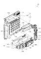
 control device 147 includes a power source and launch control board housed in a board box 149, and a predetermined power source required for various control devices and the like is generated and output by the board. Control of the launch of the game ball accompanying the operation of the firing handle 84 is performed. The power supply and launch control device 147 is provided with a RAM erase switch 149a. This pachinko machine 10 has a function to store and store various data so that even if a power failure occurs, it maintains the state at the time of the power failure, and when it recovers from the power failure, it can be restored to the state at the time of the power failure. It has become. Therefore, for example, when the power supply is turned off in the normal procedure, as in the case of the game hall being closed, the state before the turn-off is stored and held. However, when the power is turned on while pressing the RAM erase switch 149a, the RAM data is initialized. It is like that.

<上下通路ユニット134>
次に、上下通路ユニット134の構成について詳細に説明する。図11は上下通路ユニット134の斜視図、図12及び図13は上下通路ユニット134の分解斜視図、図14は上下通路ユニット134に形成された通路の一部の構成を説明するための説明図である。
<Vertical passage unit 134>
Next, the configuration of the vertical passage unit 134 will be described in detail. 11 is a perspective view of the upper and lower passage unit 134, FIGS. 12 and 13 are exploded perspective views of the upper and lower passage unit 134, and FIG. 14 is an explanatory diagram for explaining a configuration of a part of the passage formed in the upper and lower passage unit 134. It is.

上下通路ユニット134は、図11に示すように、上側ユニット161と、払出装置135と、下側ユニット162とを備えている。これら上側ユニット161、払出装置135及び下側ユニット162が上下通路ユニット134として一体化されていることにより、上皿95a及び下皿96aへ通じる誘導通路部の一部が形成されている。また、上側ユニット161及び下側ユニット162により、タンク132に貯留されている遊技球を島設備に排出するための排出通路部が形成されている。これら上側ユニット161、払出装置135及び下側ユニット162について詳細に説明する。   As shown in FIG. 11, the vertical passage unit 134 includes an upper unit 161, a dispensing device 135, and a lower unit 162. The upper unit 161, the dispensing device 135, and the lower unit 162 are integrated as an upper and lower passage unit 134, thereby forming a part of a guide passage portion that communicates with the upper plate 95a and the lower plate 96a. Further, the upper unit 161 and the lower unit 162 form a discharge passage portion for discharging the game balls stored in the tank 132 to the island facility. The upper unit 161, the dispensing device 135, and the lower unit 162 will be described in detail.

上側ユニット161は、図12及び図13に示すように、ポリカーボネートなどといった透明性を有する合成樹脂により形成された一対のハウジング部材171,172を備えている。各ハウジング部材171,172には、それぞれ通路壁が一体形成されている。これらハウジング部材171,172は両者の間に、ハウジング部材171,172と同様に透明性を有する合成樹脂により形成された仕切板173を挟んだ状態で前後に組み付けられている。これにより、図14に示すように、パチンコ機10後側のハウジング部材171と仕切板173により第1ケースレール部174が形成されているとともに、パチンコ機10前側のハウジング部材172と仕切板173により第2ケースレール部175が形成されている。   As shown in FIGS. 12 and 13, the upper unit 161 includes a pair of housing members 171 and 172 formed of a synthetic resin having transparency such as polycarbonate. Each housing member 171, 172 is integrally formed with a passage wall. These housing members 171 and 172 are assembled in the front-rear direction with a partition plate 173 formed of a synthetic resin having transparency in the same manner as the housing members 171 and 172. Accordingly, as shown in FIG. 14, the first case rail portion 174 is formed by the housing member 171 and the partition plate 173 on the rear side of the pachinko machine 10, and the housing member 172 and partition plate 173 on the front side of the pachinko machine 10. A second case rail portion 175 is formed.

なお、一対のハウジング部材171,172に対しては、両者を前後に挟むようにして外側カバー176が取り付けられているとともに、パチンコ機10の搬送時等においてコンセントプラグを保持するための保持部材177が取り付けられている。   An outer cover 176 is attached to the pair of housing members 171 and 172 so as to sandwich both of them, and a holding member 177 for holding an outlet plug is attached when the pachinko machine 10 is transported. It has been.

第1ケースレール部174及び第2ケースレール部175は前後に並設されており、上下方向の途中位置に湾曲部を有するように蛇行させて形成されている。第1ケースレール部174及び第2ケースレール部175は、共に上記誘導通路部の一部を構成している。   The first case rail part 174 and the second case rail part 175 are juxtaposed in the front-rear direction, and are formed to meander so as to have a curved part at an intermediate position in the vertical direction. Both the first case rail portion 174 and the second case rail portion 175 constitute a part of the guide passage portion.

上側ユニット161には、図14に示すように、第1ケースレール部174及び第2ケースレール部175の他に、上側排出通路部178が形成されている。上側排出通路部178は、一対のハウジング部材171,172間において仕切板173により仕切られていない領域に形成されており、第1ケースレール部174及び第2ケースレール部175よりもパチンコ機10外側に位置している。上側排出通路部178は、第1ケースレール部174及び第2ケースレール部175の両方に対してそれらの途中位置から分岐させて設けられている。   In the upper unit 161, as shown in FIG. 14, in addition to the first case rail portion 174 and the second case rail portion 175, an upper discharge passage portion 178 is formed. The upper discharge passage portion 178 is formed in a region that is not partitioned by the partition plate 173 between the pair of housing members 171 and 172, and is outside the pachinko machine 10 than the first case rail portion 174 and the second case rail portion 175. Is located. The upper discharge passage portion 178 is provided to be branched from both the first case rail portion 174 and the second case rail portion 175 from the middle position thereof.

ここで、上側排出通路部178の入口部分には、切換片181が設けられている。切換片181は、前後方向を回動軸として、両ハウジング部材171,172に対して回動可能に支持されている。切換片181は、両ハウジング部材171,172の間に内蔵されている。また、切換片181よりもパチンコ機10外側には切換操作片182が設けられている。当該切換操作片182も切換片181と同様に、前後方向を回動軸として、両ハウジング部材171,172に対して回動可能に支持されている。   Here, a switching piece 181 is provided at the inlet portion of the upper discharge passage portion 178. The switching piece 181 is supported so as to be rotatable with respect to both housing members 171 and 172 with the front-rear direction as a rotation axis. The switching piece 181 is built in between both housing members 171 and 172. Further, a switching operation piece 182 is provided outside the pachinko machine 10 with respect to the switching piece 181. Similarly to the switching piece 181, the switching operation piece 182 is supported so as to be rotatable with respect to both housing members 171 and 172, with the front-rear direction serving as a rotation axis.

切換操作片182は、両ハウジング部材171,172内に位置する押圧部183と、両ハウジング部材171,172外に位置するレバー部184とを有している。切換操作片182は、レバー部184を操作して回動させることで、押圧部183が切換片181を押圧する押圧位置と、当該押圧を解除する押圧解除位置とに切換配置可能となっている。   The switching operation piece 182 has a pressing portion 183 located in both housing members 171 and 172 and a lever portion 184 located outside both housing members 171 and 172. The switching operation piece 182 can be switched and arranged between a pressing position where the pressing portion 183 presses the switching piece 181 and a press releasing position where the pressing is released by operating and turning the lever portion 184. .

切換操作片182を、図14の実線で示すように、押圧位置に配置した場合には、上記のとおり切換操作片182の押圧部183により切換片181が押圧され、当該切換片181は第1ケースレール部174及び第2ケースレール部175の通路壁の一部を構成する。また、この通路壁を構成する位置では、第1ケースレール部174及び第2ケースレール部175は湾曲しており、切換片181は上記通路壁における底部側を構成している。ちなみに、押圧部183により押圧されて切換片181が第1ケースレール部174及び第2ケースレール部175の通路壁を構成している状態が、払出誘導状態に相当する。切換片181が払出誘導状態である場合には、切換片181よりも上流側の遊技球は、第1ケースレール部174及び第2ケースレール部175をそのまま流下していく。   When the switching operation piece 182 is arranged at the pressing position as shown by the solid line in FIG. 14, the switching piece 181 is pressed by the pressing portion 183 of the switching operation piece 182 as described above, and the switching piece 181 Part of the passage walls of the case rail portion 174 and the second case rail portion 175 is configured. Moreover, in the position which comprises this channel | path wall, the 1st case rail part 174 and the 2nd case rail part 175 are curving, and the switching piece 181 has comprised the bottom part side in the said channel | path wall. Incidentally, the state where the switching piece 181 is pressed by the pressing portion 183 to form the passage walls of the first case rail portion 174 and the second case rail portion 175 corresponds to the payout guiding state. When the switching piece 181 is in the payout guidance state, the game ball upstream of the switching piece 181 flows down the first case rail portion 174 and the second case rail portion 175 as it is.

一方、切換操作片182を、図14の二点鎖線で示すように、押圧解除位置に配置した場合には、押圧部183による切換片181の押圧状態が解除される。これにより、切換片181は自重により回動し、第1ケースレール部174及び第2ケースレール部175の通路壁を構成しない状態となる。ちなみに、押圧部183による押圧が解除されて切換片181が第1ケースレール部174及び第2ケースレール部175の通路壁を構成していない状態が、排出誘導状態に相当する。切換片181が排出誘導状態である場合には、切換片181よりも上流側の遊技球は、上側排出通路部178側に流れていく。切換操作片182は通常、切換片181が払出誘導状態となる位置に配置されており、パチンコ機10内部の遊技球を抜き出す場合に、切換片181が排出誘導状態となるように切換配置される。   On the other hand, when the switching operation piece 182 is arranged at the pressing release position as shown by a two-dot chain line in FIG. 14, the pressing state of the switching piece 181 by the pressing portion 183 is released. As a result, the switching piece 181 is rotated by its own weight and does not constitute the passage walls of the first case rail portion 174 and the second case rail portion 175. Incidentally, the state where the pressing by the pressing portion 183 is released and the switching piece 181 does not constitute the passage walls of the first case rail portion 174 and the second case rail portion 175 corresponds to the discharge guiding state. When the switching piece 181 is in the discharge inducing state, the game ball upstream of the switching piece 181 flows toward the upper discharge passage portion 178 side. The switching operation piece 182 is normally arranged at a position where the switching piece 181 is in the payout guidance state, and when the game ball inside the pachinko machine 10 is pulled out, the switching piece 181 is switched and arranged so as to be in the discharge guidance state. .

上側ユニット161は、タンク132の球無状態を検知するための球無検知センサ186を備えている。球無検知センサ186は、第1ケースレール部174及び第2ケースレール部175における切換片181よりも上流側において遊技球を検知するように設けられており、第1ケースレール部174及び第2ケースレール部175のそれぞれに対応させて検知部187a,187bを備えている。なお、本パチンコ機10では、球無検知センサ186として、検知部187a,187bに設けられた突出片が遊技球に押圧されていない場合に球無検知信号を出力するセンサが用いられているが、どのようなセンサを用いるかは任意である。球無検知センサ186の検知結果は払出制御装置146に出力され、払出制御装置146では球無検知センサ186の検知結果に基づいて球無状態か否かの特定を行う。   The upper unit 161 includes a sphere absence detection sensor 186 for detecting the absence of a sphere in the tank 132. The ball non-detection sensor 186 is provided so as to detect a game ball on the upstream side of the switching piece 181 in the first case rail portion 174 and the second case rail portion 175, and the first case rail portion 174 and the second case rail portion 174. Detection units 187a and 187b are provided corresponding to the case rail portions 175, respectively. In the pachinko machine 10, the ball non-detection sensor 186 uses a sensor that outputs a ball non-detection signal when the protruding pieces provided on the detection units 187a and 187b are not pressed by the game ball. What kind of sensor is used is arbitrary. The detection result of the ball non-detection sensor 186 is output to the payout control device 146, and the payout control device 146 determines whether or not there is no ball based on the detection result of the ball non-detection sensor 186.

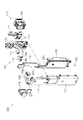
次に、払出装置135について説明する。図15は払出装置135の分解斜視図である。なお、当該払出装置135の説明では、図12〜図14を適宜参照する。   Next, the payout device 135 will be described. FIG. 15 is an exploded perspective view of the dispensing device 135. In the description of the payout device 135, FIGS.

払出装置135は、図12及び図13に示すように、下側ユニット162の上部に組み付けられている。払出装置135は、複数の部材が組み合わされてなるハウジング191を備えており、ハウジング191内には遊技球通路192が形成されている。遊技球通路192は、誘導通路部の一部を構成している。   As shown in FIGS. 12 and 13, the payout device 135 is assembled to the upper part of the lower unit 162. The payout device 135 includes a housing 191 formed by combining a plurality of members, and a game ball passage 192 is formed in the housing 191. The game ball passage 192 constitutes a part of the guide passage portion.

遊技球通路192は、一対の入口側通路部193a,193bと、単一の出口側通路部194とを備えている。入口側通路部193a,193bは前後に並設されており、いずれもハウジング191の上面にて開放されている。これら入口側通路部193a,193bのうち、一方が第1ケースレール部174と連通しており、他方が第2ケースレール部175と連通している。入口側通路部193a,193bは、その最下流部にて出口側通路部194に合流している。出口側通路部194は、ハウジング191の下面にて開放されている。   The game ball passage 192 includes a pair of inlet-side passage portions 193a and 193b and a single outlet-side passage portion 194. The inlet-side passage portions 193a and 193b are arranged side by side in front and rear, and both are open on the upper surface of the housing 191. One of the inlet side passage portions 193 a and 193 b communicates with the first case rail portion 174, and the other communicates with the second case rail portion 175. The inlet-side passage portions 193a and 193b merge with the outlet-side passage portion 194 at the most downstream portion. The outlet side passage portion 194 is opened at the lower surface of the housing 191.

払出装置135には、入口側通路部193a,193bから出口側通路部194へ流れる遊技球を入口側通路部193a,193b側にて一旦停止させるための球止め手段として、回転体195が設けられている。回転体195は、図15に示すように、各入口側通路部193a,193bに対応させて一対の球誘導板196,197を備えており、各球誘導板196,197が対応する入口側通路部193a,193bの下流部に収容されるようにして回転体195が配置されている。回転体195はその中心が払出モータ198の出力軸198aに固定されている。   The payout device 135 is provided with a rotating body 195 as ball stopping means for temporarily stopping the game ball flowing from the inlet side passage portions 193a and 193b to the outlet side passage portion 194 on the inlet side passage portions 193a and 193b side. ing. As shown in FIG. 15, the rotator 195 includes a pair of ball guide plates 196 and 197 corresponding to the respective inlet-side passage portions 193a and 193b, and the inlet-side passages corresponding to the respective ball guide plates 196 and 197. The rotating body 195 is disposed so as to be accommodated in the downstream portion of the portions 193a and 193b. The center of the rotating body 195 is fixed to the output shaft 198a of the dispensing motor 198.

払出モータ198は、ステッピングモータにより構成されており、出力軸198aは所定方向に回転駆動される。これにより、回転体195は、その所定方向に回転し、それに伴って各球誘導板196,197が各入口側通路部193a,193b内にて回転する。出力軸198aは、1パルスの駆動信号を与えることにより1step進み、360パルスの駆動信号を与えることにより1回転するように設定されている。なお、払出モータ198はハウジング191内に収容されている。   The payout motor 198 is constituted by a stepping motor, and the output shaft 198a is rotationally driven in a predetermined direction. Thereby, the rotator 195 rotates in the predetermined direction, and accordingly, the ball guide plates 196 and 197 rotate in the inlet side passage portions 193a and 193b. The output shaft 198a is set to advance one step by giving a driving signal of one pulse and to make one rotation by giving a driving signal of 360 pulses. The payout motor 198 is accommodated in the housing 191.

各球誘導板196,197の周縁には、180°間隔で2箇所に、凹部196a,197aが形成されている。但し、一対の入口側通路部193a,193b間では、凹部196a,197aの位置が相互に90°ずらして形成されている。回転体195が回転していない場合には、一対の入口側通路部193a,193bの両方において遊技球の流下が一旦停止される。また、回転体195が回転している場合には、凹部196a,197a上に入り込んだ遊技球のみが出口側通路部194に導出される。   Concave portions 196a and 197a are formed at two positions at 180 ° intervals on the periphery of each of the ball guide plates 196 and 197. However, the positions of the recesses 196a and 197a are shifted by 90 ° from each other between the pair of inlet-side passage portions 193a and 193b. When the rotating body 195 is not rotating, the flow of the game ball is temporarily stopped in both the pair of inlet side passage portions 193a and 193b. Further, when the rotating body 195 is rotating, only the game balls that have entered the recesses 196a and 197a are led out to the outlet side passage portion 194.

出口側通路部194には、図15に示すように、略平板状をした払出検知センサ199が設置されている。払出検知センサ199は、周知の磁気検知タイプの近接センサにて構成されており、貫通孔を遊技球が通過したことによる磁界の変化を電気信号に変換して出力する。この払出検知センサ199により、払出装置135を介して払い出された遊技球の数が確認できるようになっている。   As shown in FIG. 15, a payout detection sensor 199 having a substantially flat plate shape is installed in the outlet side passage portion 194. The payout detection sensor 199 is configured by a known magnetic detection type proximity sensor, and converts a magnetic field change caused by the passing of the game ball through the through hole into an electric signal and outputs it. With the payout detection sensor 199, the number of game balls paid out via the payout device 135 can be confirmed.

次に、下側ユニット162について説明する。   Next, the lower unit 162 will be described.

下側ユニット162は、図12に示すように、一対のハウジング部材201,202を備えており、両ハウジング部材201,202が前後に組み付けられて、上下方向に延びる払出通路部203が内部に形成されている。払出通路部203は、誘導通路部の一部を構成している。払出通路部203は払出装置135の出口側通路部194に連通されており、払出装置135から払い出された遊技球は払出通路部203を通過する。払出通路部203の下流側には仕切壁204が形成されており、払出通路部203は下流側にて2列に分岐している。これら2列の通路のうち、一方により遊技球が上皿95aへ誘導され、他方により遊技球が下皿96aへ誘導される。この誘導の様子については、後に説明する。   As shown in FIG. 12, the lower unit 162 includes a pair of housing members 201 and 202, and both housing members 201 and 202 are assembled in the front-rear direction to form a dispensing passage portion 203 extending in the vertical direction. Has been. The payout passage portion 203 constitutes a part of the guide passage portion. The payout passage portion 203 communicates with the outlet side passage portion 194 of the payout device 135, and the game ball paid out from the payout device 135 passes through the payout passage portion 203. A partition wall 204 is formed on the downstream side of the payout passage portion 203, and the payout passage portion 203 is branched into two rows on the downstream side. Of these two rows of passages, the game ball is guided to the upper plate 95a by one and the game ball is guided to the lower plate 96a by the other. The state of this guidance will be described later.

下側ユニット162には、払出通路部203以外にも下側排出通路部205が形成されている。下側排出通路部205は上下方向に延びており、払出通路部203よりもパチンコ機10外側に位置している。また、払出通路部203よりも上方に延長させて形成されており、上側ユニット161の上側排出通路部178に連通している。これにより、上側排出通路部178へ誘導された遊技球は、下側排出通路部205を通過することとなる。   In the lower unit 162, a lower discharge passage portion 205 is formed in addition to the payout passage portion 203. The lower discharge passage portion 205 extends in the vertical direction, and is located on the outer side of the pachinko machine 10 with respect to the payout passage portion 203. Further, it is formed to extend upward from the payout passage portion 203 and communicates with the upper discharge passage portion 178 of the upper unit 161. Thereby, the game ball guided to the upper discharge passage portion 178 passes through the lower discharge passage portion 205.

下側ユニット162には、既に説明した裏パック基板136が搭載されている。ここで、裏パック基板136には、図12に示すように、球抜きボタン206が設けられている。本パチンコ機10では、上記のとおり球無検知センサ186が設けられており、球無検知センサ186にて球無状態が検知されている状況では払出装置135の払出動作が停止される。この場合に、球抜きボタン206が操作されることにより、上記動作停止状態が解除され、払出装置135の払出動作が可能となる。   The back pack substrate 136 described above is mounted on the lower unit 162. Here, the back pack substrate 136 is provided with a ball removal button 206 as shown in FIG. In the pachinko machine 10, the ball non-detection sensor 186 is provided as described above, and the payout operation of the payout device 135 is stopped in a situation where the ball non-detection sensor 186 detects a ball non-detection state. In this case, when the ball removal button 206 is operated, the operation stop state is released, and the payout operation of the payout device 135 becomes possible.

以上のとおり、上下通路ユニット134には、上側ユニット161の第1ケースレール部174及び第2ケースレール部175と、払出装置135の遊技球通路192と、下側ユニット162の払出通路部203とが設けられている。そして、タンクレール133から流下してきた遊技球は基本的に、これら通路部174,175,192,203を通じて上皿95a又は下皿96aに向けて誘導される。また、上下通路ユニット134には、上側ユニット161の上側排出通路部178と、下側ユニット162の下側排出通路部205とが設けられている。そして、切換操作片182を操作して切換片181を排出誘導状態とすることにより、切換片181よりも上流側にある遊技球が、これら上側排出通路部178及び下側排出通路部205を通じてパチンコ機10外の島設備に向けて誘導される。   As described above, the vertical passage unit 134 includes the first case rail portion 174 and the second case rail portion 175 of the upper unit 161, the game ball passage 192 of the payout device 135, and the payout passage portion 203 of the lower unit 162. Is provided. The game balls flowing down from the tank rail 133 are basically guided toward the upper plate 95a or the lower plate 96a through the passage portions 174, 175, 192, and 203. Further, the upper and lower passage unit 134 is provided with an upper discharge passage portion 178 of the upper unit 161 and a lower discharge passage portion 205 of the lower unit 162. Then, by operating the switching operation piece 182 to bring the switching piece 181 into the discharge guiding state, the game ball located upstream from the switching piece 181 passes through the upper discharge passage portion 178 and the lower discharge passage portion 205, and It is guided toward the island facility outside the machine 10.

<残存遊技球数について>
ここで、上記のとおり切換片181を排出誘導状態とすることで遊技球が排出通路部178,205側へ誘導されることとなるが、全ての遊技球を排出することはできない。つまり、切換片181は、既に説明したように上側排出通路部178の入口部分に設置されており、この位置は第1ケースレール部174及び第2ケースレール部175の途中位置となっている。また、払出装置135において回転体195により遊技球が一旦停止される位置は、遊技球通路192の途中位置となっている。したがって、切換片181を排出誘導状態としたとしても、切換片181の直下流側から回転体195の位置にはある程度の遊技球が残ることとなる。
<Number of remaining game balls>
Here, by setting the switching piece 181 to the discharge guiding state as described above, the game balls are guided to the discharge passage portions 178 and 205 side, but all the game balls cannot be discharged. That is, the switching piece 181 is installed at the inlet portion of the upper discharge passage portion 178 as described above, and this position is an intermediate position between the first case rail portion 174 and the second case rail portion 175. Further, the position at which the game ball is temporarily stopped by the rotating body 195 in the payout device 135 is an intermediate position in the game ball passage 192. Therefore, even if the switching piece 181 is set in the discharge induction state, a certain amount of game balls remain at the position of the rotating body 195 from the downstream side of the switching piece 181.

この場合に、本パチンコ機10では、上記残存遊技球数が特徴的な数となっている。そこで、当該残存遊技球数について、図16及び図17を用いて説明する。図16及び図17は、残存遊技球数を説明するための説明図である。   In this case, in the pachinko machine 10, the number of remaining game balls is a characteristic number. The number of remaining game balls will be described with reference to FIGS. 16 and 17 are explanatory diagrams for explaining the number of remaining game balls.

既に説明したように、第1ケースレール部174及び第2ケースレール部175は上下方向の途中位置にて湾曲部を有するように蛇行させて形成されているが、切換片181よりも下流側の通路形状が第1ケースレール部174と第2ケースレール部175とで異なっている。   As already described, the first case rail portion 174 and the second case rail portion 175 are formed to meander so as to have a curved portion at an intermediate position in the vertical direction, but are located downstream of the switching piece 181. The shape of the passage is different between the first case rail portion 174 and the second case rail portion 175.

詳細には、第1ケースレール部174における切換片181の下流側の第1待機領域211は、その下流部に横向きU字状に形成されたU字領域212を備えており、第1待機領域211における最上流部からU字領域212に至る領域は一定角度に傾斜させて直線的に形成されている。   Specifically, the first standby region 211 on the downstream side of the switching piece 181 in the first case rail portion 174 includes a U-shaped region 212 formed in a U-shape in the lateral direction at the downstream portion, and the first standby region A region from the most upstream portion 211 to the U-shaped region 212 is linearly formed with a predetermined angle.

一方、第2ケースレール部175における切換片181の下流側の第2待機領域213は、第1待機領域211と同様に、その下流部に横向きU字状に形成されたU字領域214を備えている。但し、第2待機領域213における最上流部からU字領域214に至る領域は上下方向に延びる上下領域215と左右方向に延びる左右領域216とから構成されており、U字領域214に至る領域までの通路長は第2ケースレール部175の方が長くなっている。なお、当該部分以外においては、第1ケースレール部174と第2ケースレール部175とで通路形状は同一となっている。また、払出装置135における一対の入口側通路部193a,193bの入口から球誘導板196,197(回転体195)までの通路長も同一となっている。   On the other hand, the second standby area 213 on the downstream side of the switching piece 181 in the second case rail portion 175 includes a U-shaped area 214 formed in a lateral U-shape on the downstream side, similarly to the first standby area 211. ing. However, the area from the most upstream area to the U-shaped area 214 in the second standby area 213 is composed of an upper and lower area 215 extending in the vertical direction and a left and right area 216 extending in the left-right direction. The passage length of the second case rail portion 175 is longer. Except for this portion, the first case rail portion 174 and the second case rail portion 175 have the same passage shape. Further, the passage lengths from the inlets of the pair of inlet side passage portions 193a and 193b to the ball guide plates 196 and 197 (rotating body 195) in the dispensing device 135 are also the same.

ちなみに、第1待機領域211と第2待機領域213との通路形状が異なっており、さらにはハウジング部材171,172及び仕切板173が透明性を有していることにより、第1ケースレール部174と第2ケースレール部175とが前後に並設された構成において、パチンコ機10背面側から第1ケースレール部174及び第2ケースレール部175の両方について遊技球の有無の確認を行うことができる。   Incidentally, the first standby region 211 and the second standby region 213 have different passage shapes, and the housing members 171, 172 and the partition plate 173 have transparency, so that the first case rail portion 174 is formed. And the second case rail part 175 are arranged side by side in front and back, it is possible to confirm the presence or absence of game balls for both the first case rail part 174 and the second case rail part 175 from the back side of the pachinko machine 10. it can.

上記のように第1ケースレール部174の第1待機領域211と第2ケースレール部175の第2待機領域213とが、相互に通路長が異なるように形成されていることにより、第1ケースレール部174において切換片181から回転体195までの位置に残存する残存遊技球数は、第2ケースレール部175において切換片181から回転体195までの位置に残存する残存遊技球数よりも遊技球1個分少ない数となる。具体的には、第1ケースレール部174における上記残存遊技球数は14個であるのに対して、第2ケースレール部175における上記残存遊技球数は15個である。なお、図16及び図17に示すように、第1ケースレール部174における上記残存遊技球数及び第2ケースレール部175における上記残存遊技球数は、回転体195の回転位置に関係なく一定となっている。   As described above, the first standby region 211 of the first case rail portion 174 and the second standby region 213 of the second case rail portion 175 are formed so that the passage lengths are different from each other. The number of remaining game balls remaining at the position from the switching piece 181 to the rotating body 195 in the rail portion 174 is larger than the number of remaining game balls remaining at the position from the switching piece 181 to the rotating body 195 in the second case rail portion 175. The number is reduced by one sphere. Specifically, the number of remaining game balls in the first case rail portion 174 is 14, whereas the number of remaining game balls in the second case rail portion 175 is 15. As shown in FIGS. 16 and 17, the number of remaining game balls in the first case rail portion 174 and the number of remaining game balls in the second case rail portion 175 are constant regardless of the rotational position of the rotating body 195. It has become.

上記のとおり本パチンコ機10では、切換片181を排出誘導状態とした場合に、切換片181から回転体195までの位置に残る残存遊技球数は14個と15個との和で、29個である。この数は、素数であり、遊技領域に設けられた入賞口に一の遊技球が入球した場合に払い出されることとなる単位遊技球数のいずれの整数倍とも一致しない数となっている。また、単位遊技球数のうち最大単位遊技球数である15個よりも大きい数となっている。   As described above, in the pachinko machine 10, when the switching piece 181 is in the discharge induction state, the number of remaining game balls remaining at the position from the switching piece 181 to the rotating body 195 is a sum of 14 and 15, 29 It is. This number is a prime number, and is a number that does not match any integer multiple of the number of unit game balls to be paid out when one game ball enters the winning opening provided in the game area. Further, the number is larger than 15 which is the maximum number of unit game balls among the number of unit game balls.

つまり、遊技領域には入賞口として、一般入賞口62、可変入賞装置63、上作動口64及び下作動口65が設けられている。このうち、一般入賞口62に一の遊技球が入球した場合に払い出される単位遊技球数は10個であり、可変入賞装置63に一の遊技球が入球した場合に払い出される単位遊技球数は15個であり、上作動口64に一の遊技球が入球した場合に払い出される単位遊技球数は3個であり、下作動口65に一の遊技球が入球した場合に払い出される単位遊技球数は4個である。そうすると、29個は、いずれの単位遊技球数の整数倍とも一致しない。   In other words, the game area is provided with a general winning port 62, a variable winning device 63, an upper operating port 64, and a lower operating port 65 as winning ports. Among these, the number of unit game balls to be paid out when one game ball enters the general winning opening 62 is 10, and the unit game ball to be paid out when one game ball enters the variable winning device 63. The number is 15, and the number of unit game balls to be paid out when one game ball enters the upper working port 64 is three, and is paid out when one game ball enters the lower working port 65. The number of unit game balls to be played is four. Then, 29 does not correspond to an integral multiple of any unit game ball number.

ここで、本パチンコ機10における上記残存遊技球の抜き出し方法は以下のとおりである。上記残存遊技球を抜き出す場合、先ず遊技機前面ユニット23を開放状態とし、遊技領域をパチンコ機10前方に露出させる。その後、遊技領域に設けられた入賞口に複数の遊技球を手入れで入球させる。入賞口に複数の遊技球を入球させることで、その入球結果が主制御装置107にて特定される。主制御装置107は入賞口への入球を特定することで、後述するように、払出制御装置146に賞球コマンドを出力する。払出制御装置146では、その賞球コマンドに対応した賞球数の情報を記憶し、本来なら、その記憶した情報に対応した賞球数の遊技球が払い出されるように払出装置135を駆動制御する。但し、この状態では、球無検知センサ186にて球無状態が検知されているため、上記駆動制御は開始されず、払出装置135の払出動作は開始されない。この場合に、球抜きボタン206を操作することで、球無状態であっても上記駆動制御が開始され、払出装置135の払出動作が開始される。これにより、上記残存遊技球が上皿95a又は下皿96aに排出されることとなる。   Here, the method of extracting the remaining game balls in the pachinko machine 10 is as follows. When extracting the remaining game balls, the gaming machine front unit 23 is first opened, and the gaming area is exposed to the front of the pachinko machine 10. Thereafter, a plurality of game balls are put into a winning opening provided in the game area. By making a plurality of game balls enter the winning opening, the result of entering the ball is specified by the main controller 107. The main control device 107 outputs a winning ball command to the payout control device 146 as will be described later by specifying the winning ball at the winning opening. The payout control device 146 stores information on the number of prize balls corresponding to the prize ball command, and normally controls the payout device 135 so that game balls having the number of prize balls corresponding to the stored information are paid out. . However, in this state, since the absence of a ball is detected by the no-ball detection sensor 186, the drive control is not started, and the payout operation of the payout device 135 is not started. In this case, by operating the ball removal button 206, the drive control is started even when there is no ball, and the payout operation of the payout device 135 is started. As a result, the remaining game ball is discharged to the upper plate 95a or the lower plate 96a.

なお、球抜きボタン206を操作することで、入賞口への遊技球の入球に関わらず払出装置135を動作させる構成も考えられるが、この場合、球抜きボタン206が不正に操作された場合には不正に遊技球が払い出されることとなってしまうため、本パチンコ機10における上記構成とすることが好ましい。   Note that a configuration in which the payout device 135 is operated by operating the ball removal button 206 regardless of the game ball entering the winning opening is also conceivable, but in this case, the ball removal button 206 is illegally operated. Therefore, it is preferable that the pachinko machine 10 has the above-described configuration.

上記のように残存遊技球の抜き出しが行われる構成において残存遊技球数は29個であるため、いずれか一の入賞口に複数の遊技球を手入れで入球させて全ての残存遊技球を排出させようとすると、その際に払出制御装置146に記憶される賞球数は上記残存遊技球数を超えることとなる。つまり、一般入賞口62を用いる場合、全ての残存遊技球を排出させるためには3個の遊技球を入球させる必要があり、賞球数は29個より1個多い30個となる。また、可変入賞装置63を用いる場合、全ての残存遊技球を排出させるためには2個の遊技球を入球させる必要があり、賞球数は29個より1個多い30個となる。また、上作動口64を用いる場合、全ての残存遊技球を排出させるためには10個の遊技球を入球させる必要があり、賞球数は29個より1個多い30個となる。また、下作動口65を用いる場合、全ての残存遊技球を排出させるためには8個の遊技球を入球させる必要があり、賞球数は29個より3個多い32個となる。これら残存遊技球数を超えた賞球数は払出制御装置146に記憶保持されることとなる。この場合に、後述するように払出制御装置146には電源及び発射制御装置147からバックアップ電力が供給されるため、パチンコ機10の電源が遮断されたとしても、上記残存遊技球数を超えた賞球数の情報は記憶保持される。   In the configuration in which the remaining game balls are extracted as described above, since the number of remaining game balls is 29, a plurality of game balls are carefully placed in any one winning opening to discharge all remaining game balls. If it is made to do, the number of prize balls memorize | stored in the payout control apparatus 146 at that time will exceed the said number of remaining game balls. That is, when the general winning opening 62 is used, it is necessary to insert three game balls in order to discharge all remaining game balls, and the number of prize balls is 30, which is one more than 29. When the variable winning device 63 is used, two game balls need to be entered in order to discharge all remaining game balls, and the number of prize balls is 30, which is one more than 29. Further, when the upper operation port 64 is used, in order to discharge all the remaining game balls, it is necessary to insert 10 game balls, and the number of prize balls is 30 which is one more than 29. Further, when the lower operation port 65 is used, in order to discharge all the remaining game balls, it is necessary to enter 8 game balls, and the number of prize balls is 32, which is 3 more than 29. The number of prize balls exceeding the number of remaining game balls is stored and held in the payout control device 146. In this case, as will be described later, backup power is supplied to the payout control device 146 from the power supply and launch control device 147, so even if the power of the pachinko machine 10 is shut off, the award exceeding the number of remaining game balls is exceeded. Information on the number of balls is stored and held.

以上説明したような遊技球の抜き出しは、例えば、パチンコ機10を中古で流通させる場合に行われる。遊技球には遊技ホール毎に固有の模様などが付されており、中古での流通に際してパチンコ機10内の遊技球を全て抜き出すことで、遊技ホール間で異なる遊技球が混ざらないようにすることができる。その一方、パチンコ機10を中古で流通する場合、その流通過程で払出制御装置146などが不正な制御装置に交換されてしまうことが懸念される。この場合、流通先の遊技ホールが多大な不利益を被ってしまうおそれがあり好ましくない。また、これを抑制すべく、払出制御装置146の不正交換を防止するために複雑な構成を付加すると、パチンコ機10のコストが高くなってしまう。   The extraction of the game balls as described above is performed, for example, when the pachinko machine 10 is used and distributed. The game balls are given a unique pattern for each game hall, and by extracting all the game balls in the pachinko machine 10 for second-hand distribution, it is ensured that different game balls are not mixed between the game halls. Can do. On the other hand, when the pachinko machine 10 is used and distributed, there is a concern that the dispensing control device 146 and the like may be replaced with an unauthorized control device during the distribution process. In this case, there is a possibility that the distribution game hall may suffer a great disadvantage, which is not preferable. Moreover, if a complicated structure is added in order to prevent the payout control device 146 from being illegally exchanged in order to suppress this, the cost of the pachinko machine 10 is increased.

これに対して、本パチンコ機10では上記のとおり、残存遊技球数が29個となっており、いずれか一の入賞口に複数の遊技球を手入れで入球させて当該残存遊技球を全て排出させようとすると、自ずと払出制御装置146に賞球数の情報が残ることとなる。そして、この賞球数の情報は、バックアップ電力が供給されることにより、パチンコ機10の電源が遮断されたとしても記憶保持される。これにより、パチンコ機10を中古で流通させる場合、流通先にて払出制御装置146に上記賞球数の情報が記憶保持されていることを確認することで、流通過程において払出制御装置146の不正交換が行われたか否かを確認することができる。この確認としては、例えば、島設備にパチンコ機10を設置し、タンク132に遊技球を補充した後に電源を立ち上げた場合に、遊技球が上皿95aに排出されるか否かを確認することで行うことができる。   On the other hand, in the present pachinko machine 10, as described above, the number of remaining game balls is 29, and a plurality of game balls are carefully placed in any one winning opening and all the remaining game balls are collected. If it is made to discharge, information on the number of prize balls will remain in the payout control device 146 by itself. The information on the number of prize balls is stored and held even when the power of the pachinko machine 10 is shut off by supplying backup power. As a result, when the pachinko machine 10 is distributed in the secondhand, by confirming that the information on the number of prize balls is stored in the payout control device 146 at the distribution destination, the payout control device 146 is illegally distributed during the distribution process. It can be confirmed whether or not the exchange has been performed. As this confirmation, for example, when the pachinko machine 10 is installed in the island facility and the power supply is turned on after the game ball is replenished to the tank 132, it is confirmed whether or not the game ball is discharged to the upper plate 95a. Can be done.

特に、本パチンコ機10では、残存遊技球数が29個に設定されているため、いずれか一の入賞口に対して上記手入れでの遊技球の入球動作を行うことで、確実に払出制御装置146に賞球数の情報が残ることとなる。よって、流通過程において払出制御装置146の不正交換が行われたか否かの確認作業を確実に行うことができる。   In particular, in the present pachinko machine 10, since the number of remaining game balls is set to 29, the payout control is surely performed by performing the above-described maintenance operation of the game balls with respect to any one winning opening. Information on the number of winning balls will remain in the device 146. Therefore, it is possible to reliably check whether or not the payout control device 146 has been illegally exchanged during the distribution process.

また、実際に上記球抜き動作を行う場合、その作業効率を考えて、単位遊技球数が最も多い可変入賞装置63を用いることが考えられる。この場合、可変入賞装置63に遊技球を2個入球させることで、払出制御装置146に記憶される賞球数の情報が30個となり、上記残存遊技球数を超えることとなる。また、払出制御装置146に記憶される賞球数の情報が30個の場合には、残存遊技球の排出後に残る賞球数は1個となる。そうすると、パチンコ機10を中古品で流通させた場合、払出制御装置146に記憶保持される賞球数の情報は1個となる。これにより、流通先でパチンコ機10の電源を立ち上げた場合に払い出される遊技球の数は1個となり、流通先での遊技ホールにおいて不正の有無の確認後における片付け作業に際してはその1個の遊技球を取り出すだけで済む。よって、当該片付け作業の作業効率を向上させることができる。つまり、本構成によれば、球抜き作業の作業効率及び片付け作業の作業効率の両方を向上させることができる。   Further, when the ball removing operation is actually performed, it is conceivable to use the variable winning device 63 having the largest number of unit game balls in consideration of the work efficiency. In this case, by entering two game balls in the variable winning device 63, the information on the number of prize balls stored in the payout control device 146 becomes 30, which exceeds the number of remaining game balls. When the information on the number of prize balls stored in the payout control device 146 is 30, the number of prize balls remaining after discharging the remaining game balls is one. Then, when the pachinko machine 10 is distributed as a used product, the information on the number of prize balls stored and held in the payout control device 146 is one. As a result, when the power source of the pachinko machine 10 is turned on at the distribution destination, the number of game balls to be paid out becomes one, and at the time of tidying up work after checking the presence / absence of fraud in the distribution hall at the distribution destination, Just take out the game ball. Therefore, the work efficiency of the tidying work can be improved. That is, according to this configuration, it is possible to improve both the work efficiency of the ball removal work and the work efficiency of the tidying work.

なお、最大単位遊技球数に対応した入賞口を用いた場合に払出制御装置146に記憶される賞球数の情報は、「残存遊技球数+1」に限定されることはなく、残存遊技球数に対する最大単位遊技球数の商の余りが最小単位遊技球数未満としてもよい。つまり、本パチンコ機10では、最小単位遊技球数が3個であるため、最大単位遊技球数に対応した入賞口を用いた場合に払出制御装置146に記憶される賞球数の情報が、「残存遊技球数+2」となるようにしてもよい。但し、この場合、残存遊技球数又は最大単位遊技球数を上記のものとは異なる数とする必要がある。   Note that the information on the number of winning balls stored in the payout control device 146 when a winning opening corresponding to the maximum number of unit playing balls is used is not limited to “the number of remaining gaming balls + 1”, and the remaining gaming balls The remainder of the quotient of the maximum unit game ball number relative to the number may be less than the minimum unit game ball number. That is, in this pachinko machine 10, since the minimum unit game ball number is 3, the information on the number of prize balls stored in the payout control device 146 when using a winning opening corresponding to the maximum unit game ball number is You may make it become "the number of remaining game balls +2." However, in this case, the number of remaining game balls or the maximum number of unit game balls must be different from the above.

また、実際に上記球抜き動作を行う場合、その作業効率を考えて、手入れでの入球作業を最も行い易い入賞口を用いることが考えられる。本パチンコ機10では、当該入賞口は、遊技盤61において遊技機前面ユニット23の回動先端側に位置する一般入賞口62である。この場合、一般入賞口62に遊技球を3個入球させることで、払出制御装置146に記憶される賞球数の情報が30個となり、上記残存遊技球数を超えることとなる。また、払出制御装置146に記憶される賞球数の情報が30個の場合には、残存遊技球数の排出後に残る賞球数は1個となる。そうすると、パチンコ機10を中古品で流通させた場合、払出制御装置146に記憶保持される賞球数の情報は1個となる。これにより、流通先でパチンコ機10の電源を立ち上げた場合に払い出される遊技球の数は1個となり、流通先での遊技ホールにおいて不正の有無の確認後における片付け作業に際してはその1個の遊技球を取り出すだけで済む。よって、当該片付け作業の作業効率を向上させることができる。つまり、本構成によれば、球抜き作業の作業効率及び片付け作業の作業効率の両方を向上させることができる。   When actually performing the above-described ball removal operation, it is conceivable to use a winning opening that makes it easier to perform the ball entry work by taking into consideration the work efficiency. In the present pachinko machine 10, the winning port is a general winning port 62 located on the rotation tip side of the gaming machine front unit 23 in the gaming board 61. In this case, by entering three game balls into the general winning opening 62, the information on the number of prize balls stored in the payout control device 146 becomes 30, which exceeds the number of remaining game balls. When the information on the number of prize balls stored in the payout control device 146 is 30, the number of prize balls remaining after the remaining number of game balls is discharged is one. Then, when the pachinko machine 10 is distributed as a used product, the information on the number of prize balls stored and held in the payout control device 146 is one. As a result, when the power source of the pachinko machine 10 is turned on at the distribution destination, the number of game balls to be paid out becomes one, and at the time of tidying up work after checking the presence / absence of fraud in the distribution hall at the distribution destination, Just take out the game ball. Therefore, the work efficiency of the tidying work can be improved. That is, according to this configuration, it is possible to improve both the work efficiency of the ball removal work and the work efficiency of the tidying work.

なお、入球作業を行い易い入賞口を用いた場合に払出制御装置146に記憶される賞球数の情報は、「残存遊技球数+1」に限定されることはなく、残存遊技球数に対する当該入賞口の単位遊技球数の商の余りが最小単位遊技球数未満としてもよい。つまり、本パチンコ機10では、最小単位遊技球数が3個であるため、上記入賞口を用いた場合に払出制御装置146に記憶される賞球数の情報が、「残存遊技球数+2」となるようにしてもよい。但し、この場合、残存遊技球数又は一般入賞口62の単位遊技球数を上記のものとは異なる数とする必要がある。   Note that the information on the number of winning balls stored in the payout control device 146 when using a winning opening that facilitates the entering work is not limited to “the number of remaining gaming balls + 1”, and the number of remaining gaming balls is not limited. The remainder of the quotient of the number of unit game balls in the winning opening may be less than the minimum number of unit game balls. That is, in this pachinko machine 10, since the minimum unit number of game balls is 3, the information on the number of prize balls stored in the payout control device 146 when the above winning opening is used is “the number of remaining game balls + 2”. You may make it become. However, in this case, it is necessary to make the number of remaining game balls or the number of unit game balls of the general winning opening 62 different from the above.

一方、残存遊技球数の29個は、例えば、一般入賞口62の単位遊技球数と、可変入賞装置63の単位遊技球数と、下作動口65の単位遊技球数との和と一致する数である。したがって、例えば、遊技ホールにおけるメンテナンス時や、製造メーカからの出荷時といった、中古品を流通させる必要がない場合には、一般入賞口62、可変入賞装置63及び下作動口65のそれぞれに1個ずつ遊技球を入球させることで、払出制御装置146に記憶される賞球数の情報は上記残存遊技球数と一致し、当該賞球数の情報が払出制御装置146に残らないようにすることができる。   On the other hand, 29 of the remaining game balls coincide with, for example, the sum of the number of unit game balls of the general winning opening 62, the number of unit game balls of the variable winning device 63, and the number of unit game balls of the lower operation port 65. Is a number. Therefore, for example, when there is no need to circulate second-hand goods, such as during maintenance in a game hall or when shipping from a manufacturer, one for each of the general winning port 62, the variable winning device 63, and the lower operating port 65. By entering the game balls one by one, the information on the number of prize balls stored in the payout control device 146 matches the number of remaining game balls so that the information on the number of prize balls does not remain in the payout control device 146. be able to.

また、残存遊技球数の29個は、一般入賞口62の単位遊技球数の2倍と、上作動口64の単位遊技球数の3倍との和と一致する数である。これら一般入賞口62及び上作動口64は、遊技球の入球を不可又は難しくする開閉手段が設けられていない入賞口であり、手入れでの入球作業に際して開閉手段の開放操作等を要しない。よって、賞球数の情報が払出制御装置146に残らないようにしながら残存遊技球の抜き出しを行う場合に、その作業効率を向上させることができる。   In addition, 29 of the remaining number of game balls is a number that is equal to the sum of twice the number of unit game balls of the general winning opening 62 and three times of the number of unit game balls of the upper operation port 64. The general winning port 62 and the upper operating port 64 are winning ports which are not provided with an opening / closing means for making it difficult or difficult for a game ball to enter, and do not require an opening / closing operation of the opening / closing means or the like in the case of entering a ball in the maintenance. . Therefore, when the remaining game balls are extracted while the information on the number of winning balls is not left in the payout control device 146, the work efficiency can be improved.

また、一般入賞口62の一部は、上記のとおり、遊技盤61において遊技機前面ユニット23の回動先端側に配置されている。また、下作動口65は、遊技盤61において左右方向の中央側に配置されている。この点、手入れでの入球作業に際して、これら一般入賞口62及び下作動口65に遊技球を入球させることで、賞球数の情報が払出制御装置146に残らないようにしながら残存遊技球の抜き出しを行う場合に、その作業効率を飛躍的に向上させることができる。   In addition, as described above, a part of the general winning opening 62 is disposed on the rotating front end side of the gaming machine front unit 23 in the gaming board 61. Further, the lower operating port 65 is disposed on the center side in the left-right direction on the game board 61. In this regard, in the case of a manually entering ball operation, the game balls are inserted into the general winning port 62 and the lower operation port 65, so that the information on the number of winning balls does not remain in the payout control device 146, and the remaining game balls The work efficiency can be drastically improved in the case of extracting.

<上下通路ユニット134よりも下流側の通路構成>
次に、上下通路ユニット134よりも下流側の通路構成について説明する。図18は遊技球の通路構成を説明するための説明図である。なお、図18においては、便宜上、遊技機ベースユニット22側及び裏パックユニット24側の通路構成について断面で示す。
<Passage configuration on the downstream side of the vertical passage unit 134>
Next, the passage configuration on the downstream side of the vertical passage unit 134 will be described. FIG. 18 is an explanatory diagram for explaining the path configuration of the game ball. In FIG. 18, for the sake of convenience, the passage configurations on the gaming machine base unit 22 side and the back pack unit 24 side are shown in cross section.

裏パックユニット24において、上下通路ユニット134の下流側には球受け部252が設けられており、上下通路ユニット134を通過した遊技球は球受け部252に導入される。球受け部252は、上下通路ユニット134を通過した遊技球を上皿95a側若しくは下皿96a側、又は第2裏パックユニット141の排出通路144に導く機能を有する。   In the back pack unit 24, a ball receiving portion 252 is provided on the downstream side of the vertical passage unit 134, and the game ball that has passed through the vertical passage unit 134 is introduced into the ball receiving portion 252. The ball receiver 252 has a function of guiding the game ball that has passed through the upper and lower passage units 134 to the upper plate 95a side or the lower plate 96a side, or to the discharge passage 144 of the second back pack unit 141.

球受け部252の構成を、図19に示す球受け部252周辺の縦断面図を参照しながら説明する。球受け部252は上方及び前方に開放しており、その内部が2つの仕切壁253a,253bによって仕切られることで3つの開口部255a,255b,255cが左右方向に並設されている。   The configuration of the ball receiving portion 252 will be described with reference to a longitudinal sectional view around the ball receiving portion 252 shown in FIG. The ball receiving portion 252 is open upward and forward, and the inside thereof is partitioned by two partition walls 253a and 253b, so that three openings 255a, 255b, and 255c are juxtaposed in the left-right direction.

これら開口部255a,255b,255cのうち、パチンコ機10内側の開口部255aは、払出通路部203における仕切壁204により仕切られた2列の通路のうち、パチンコ機10内側の通路の下方に位置しているとともに、上皿95aへ続く上皿通路に通じている。また、中央の開口部255bは、払出通路部203における仕切壁204により仕切られた2列の通路のうち、パチンコ機10外側の通路の下方に位置しているとともに、下皿96aへ続く下皿通路に通じている。また、外側の開口部255cは、下側排出通路部205の下方に位置しているとともに、第2裏パックユニット141の排出通路144に通じている。   Of these openings 255a, 255b, and 255c, the opening 255a inside the pachinko machine 10 is located below the passage inside the pachinko machine 10 out of the two rows of passages partitioned by the partition wall 204 in the payout passage 203. And leads to an upper plate passage that continues to the upper plate 95a. The central opening 255b is located below the passage on the outside of the pachinko machine 10 out of the two rows of passages partitioned by the partition wall 204 in the payout passage portion 203, and is a lower plate continuing to the lower plate 96a. It leads to the passage. Further, the outer opening 255c is positioned below the lower discharge passage portion 205 and communicates with the discharge passage 144 of the second back pack unit 141.

上皿通路は、裏パックユニット24に設けられた裏パック側上皿通路部258と、遊技機ベースユニット22に設けられた本体側上皿通路部262と、遊技機前面ユニット23に設けられた前面側上皿通路部272とから構成されている。同様に、下皿通路は、裏パックユニット24に設けられた裏パック側下皿通路部259と、遊技機ベースユニット22に設けられた本体側下皿通路部263と、遊技機前面ユニット23に設けられた前面側下皿通路部273とから構成されている。   The upper plate passage is provided in the back pack side upper plate passage portion 258 provided in the back pack unit 24, the main body side upper plate passage portion 262 provided in the gaming machine base unit 22, and the gaming machine front unit 23. It is composed of a front side upper dish passage portion 272. Similarly, the lower plate passage is connected to the back pack side lower plate passage portion 259 provided in the back pack unit 24, the main body side lower plate passage portion 263 provided in the gaming machine base unit 22, and the gaming machine front unit 23. The front side lower dish passage portion 273 is provided.

これら各通路部258,259,262,263,272,273について詳細に説明する。   Each of these passage portions 258, 259, 262, 263, 272, and 273 will be described in detail.

<裏パック側通路部258,259>
裏パック側上皿通路部258及び裏パック側下皿通路部259は、裏パックユニット24の回動基端側においてベース部126を前後方向に貫通するようにして設けられた裏パック側通路ユニット257に形成されている(図18参照)。裏パック側上皿通路部258及び裏パック側下皿通路部259は通路壁によって区画され左右方向に並設されている。また、裏パック側上皿通路部258及び裏パック側下皿通路部259は、それぞれ前後方向に延びており、下流側に向けて下り傾斜となっている。以上の構成において裏パック側上皿通路部258及び裏パック側下皿通路部259に導入された遊技球は、底部258a,259a上を転がった後に本体側上皿通路部262及び本体側下皿通路部263のそれぞれに排出される。
<Back pack side passage portions 258, 259>
The back pack side upper plate passage portion 258 and the back pack side lower plate passage portion 259 are provided so as to penetrate the base portion 126 in the front-rear direction on the rotation base end side of the back pack unit 24. 257 (see FIG. 18). The back pack side upper dish passage portion 258 and the back pack side lower dish passage portion 259 are partitioned by a passage wall and arranged side by side in the left-right direction. Further, the back pack side upper dish passage portion 258 and the back pack side lower dish passage portion 259 each extend in the front-rear direction and are inclined downward toward the downstream side. In the above configuration, the game balls introduced into the back pack side upper dish passage portion 258 and the back pack side lower dish passage portion 259 roll on the bottom portions 258a, 259a and then the main body side upper dish passage portion 262 and the main body side lower plate. It is discharged to each of the passage portions 263.

<本体側通路部262,263>
本体側上皿通路部262及び本体側下皿通路部263は、遊技機ベースユニット22の回動基端側において樹脂ベース41を前後方向に貫通するようにして設けられた本体側通路ユニット261に形成されている。
<Main body side passage portions 262, 263>
The main body side upper dish passage portion 262 and the main body side lower dish passage portion 263 are provided on the main body side passage unit 261 provided so as to penetrate the resin base 41 in the front-rear direction on the rotation base end side of the gaming machine base unit 22. Is formed.

本体側上皿通路部262及び本体側下皿通路部263は、仕切用通路壁264によって区画されて左右方向に並設されており、それぞれ球出口262a,263aが下方を向くようにして形成されている。詳細には、本体側上皿通路部262及び本体側下皿通路部263の上流側は下流側に向けて下り傾斜となっており、その下流側では若干下方に延出させて球出口262a,263aが形成されている。以上の構成において本体側上皿通路部262及び本体側下皿通路部263に導入された遊技球は、底部262b,263b上を転がり球出口262a,263aを介して前面側上皿通路部272及び前面側下皿通路部273のそれぞれに排出される。   The main body side upper dish passage portion 262 and the main body side lower dish passage portion 263 are partitioned by a partition passage wall 264 and arranged in parallel in the left-right direction, and are formed so that the ball outlets 262a and 263a face downward. ing. Specifically, the upstream side of the main body side upper dish passage portion 262 and the main body side lower dish passage portion 263 is inclined downward toward the downstream side, and on the downstream side, it extends slightly downward so that the ball outlet 262a, 263a is formed. The game balls introduced into the main body side upper dish passage portion 262 and the main body side lower dish passage portion 263 in the above configuration roll on the bottom portions 262b, 263b and the front side upper dish passage portion 272 through the ball outlets 262a, 263a. It is discharged into each of the front side lower dish passage portions 273.

<前面側通路部272,273>
前面側上皿通路部272及び前面側下皿通路部273は、遊技機前面ユニット23の背面に設けられた前面側通路ユニット271に形成されている。ここで、前面側通路ユニット271について図20〜図22を用いて説明する。図20は前面側通路ユニット271の斜視図、図21は前面側通路ユニット271の分解斜視図、図22は前面側通路ユニット271の正面図である。
<Front side passage portions 272, 273>
The front side upper dish passage portion 272 and the front side lower dish passage portion 273 are formed in a front side passage unit 271 provided on the back surface of the gaming machine front unit 23. Here, the front-side passage unit 271 will be described with reference to FIGS. 20 is a perspective view of the front side passage unit 271, FIG. 21 is an exploded perspective view of the front side passage unit 271, and FIG. 22 is a front view of the front side passage unit 271.

前面側通路ユニット271は、図21に示すように一対のベース板274a,274bを有している。これらベース板274a,274bはポリカーボネート樹脂などといった透明性を有する合成樹脂材料により形成されており、それぞれ溝部や開口部が形成されている。両ベース板274a,274bがネジ固定されていることで、前面側上皿通路部272を構成する受口部275が形成されているとともに、少なくとも前面側下皿通路部273を構成する通路形成部276が形成されている。なお、前面側通路ユニット271は受口部275及び通路形成部276の他に板状部271aを有している。この前面側通路ユニット271は、前面側上皿通路部272の出口272aが上皿95aの球入口と前後に重なり、前面側下皿通路部273の出口273aが下皿96aの球入口と前後に重なるようにして、遊技機前面ユニット23の背面に対してパチンコ機10後方からネジ固定されている。   The front side passage unit 271 has a pair of base plates 274a and 274b as shown in FIG. These base plates 274a and 274b are formed of a transparent synthetic resin material such as polycarbonate resin, and have a groove and an opening, respectively. Since both the base plates 274a and 274b are fixed by screws, a receiving portion 275 constituting the front upper dish passage portion 272 is formed, and at least a passage forming portion constituting the front lower tray passage portion 273. 276 is formed. The front-side passage unit 271 has a plate-like portion 271a in addition to the receiving portion 275 and the passage forming portion 276. In the front side passage unit 271, the outlet 272 a of the front side upper dish passage part 272 overlaps with the front and rear of the ball entrance of the upper dish 95 a, and the outlet 273 a of the front side lower dish passage part 273 extends back and forth with the ball inlet of the lower dish 96 a. The screws are fixed from behind the pachinko machine 10 to the back of the gaming machine front unit 23 so as to overlap.

前面側通路ユニット271の受口部275及び通路形成部276について説明する。受口部275が形成された位置は前面側通路ユニット271において上側隅部であり、遊技機前面ユニット23との関係では当該遊技機前面ユニット23の回動基端側となっている。また、受口部275は、通路形成部276よりもパチンコ機10の後方に突出しており、さらには遊技機前面ユニット23の回動軸よりもパチンコ機10の後方にある。そして、遊技機前面ユニット23を閉鎖した状態において、受口部275は遊技機ベースユニット22の前側端部よりも後側に入り込んでいる。   The receiving part 275 and the passage forming part 276 of the front side passage unit 271 will be described. The position where the receiving portion 275 is formed is the upper corner of the front-side passage unit 271, and is the rotation base end side of the gaming machine front unit 23 in relation to the gaming machine front unit 23. In addition, the receiving portion 275 protrudes rearward of the pachinko machine 10 from the passage forming portion 276, and is further rearward of the pachinko machine 10 than the rotation shaft of the gaming machine front unit 23. And in the state which closed the game machine front unit 23, the opening part 275 has entered into the back rather than the front side edge part of the game machine base unit 22. FIG.

但し、受口部275は遊技機ベースユニット22の後側端部よりも前側にあり、遊技機ベースユニット22(樹脂ベース41)には受口部275と対峙する位置に、当該受口部275の突出側をカバーするカバー部としての収容凹部292bが形成されている(図23参照)。よって、遊技機前面ユニット23を閉鎖した状態において受口部275は遊技機ベースユニット22を前後方向に貫通していない。   However, the receiving portion 275 is in front of the rear end portion of the gaming machine base unit 22, and the receiving portion 275 is located at a position facing the receiving portion 275 in the gaming machine base unit 22 (resin base 41). A housing recess 292b is formed as a cover portion that covers the protruding side of the housing (see FIG. 23). Therefore, in a state where the gaming machine front unit 23 is closed, the receiving portion 275 does not penetrate the gaming machine base unit 22 in the front-rear direction.

受口部275は図20等に示すように上方に開放されており、その左右方向の略中央には底部から上方に起立した仕切壁277が一体形成されている。この仕切壁277に仕切られることで、受口部275には2つの開口部278,279が左右方向に並設されている。かかる構成において、受口部275におけるパチンコ機10内側の側壁はパチンコ機10後側などに比べ背が高くなっており、当該側壁には庇部275aが形成されている。この庇部275aが形成されていることにより、上記2つの開口部278,279のうちパチンコ機10内側の開口部278はパチンコ機10外側の開口部279よりも幅寸法(左右方向寸法)が小さくなっている。   As shown in FIG. 20 and the like, the receiving portion 275 is opened upward, and a partition wall 277 erected upward from the bottom is integrally formed at the approximate center in the left-right direction. By being partitioned by the partition wall 277, the opening portion 275 has two openings 278 and 279 arranged in parallel in the left-right direction. In such a configuration, the inner side wall of the pachinko machine 10 in the receiving portion 275 is taller than the rear side of the pachinko machine 10 and the like, and a flange 275a is formed on the side wall. Due to the formation of the flange 275a, the opening 278 inside the pachinko machine 10 out of the two openings 278 and 279 has a smaller width dimension (lateral dimension) than the opening 279 outside the pachinko machine 10. It has become.

パチンコ機10内側の開口部278は、本体側上皿通路部262の球出口262aと上下に対峙しており、図22等に示すように、前面側上皿通路部272の球入口となっている。また、パチンコ機10外側の開口部279は、本体側下皿通路部263の球出口263aと上下に対峙しており、通路形成部276に形成される前面側下皿通路部273の球入口となっている。この場合に、上記のとおり、受口部275は遊技機ベースユニット22の前側端部よりも後側に入り込んでいるため、前面側上皿通路部272と本体側上皿通路部262との境界部分、及び前面側下皿通路部273と本体側下皿通路部263との境界部分は、その一部が遊技機ベースユニット22の前側端部よりも後側に入り込んでいる(図18等参照)。   The opening 278 inside the pachinko machine 10 is vertically opposed to the ball outlet 262a of the main body side upper dish passage 262, and serves as a ball inlet of the front side upper dish passage 272 as shown in FIG. Yes. Further, the opening 279 outside the pachinko machine 10 faces the ball outlet 263a of the main body side lower dish passage part 263 in the vertical direction, and the ball inlet of the front side lower dish passage part 273 formed in the passage forming part 276 It has become. In this case, as described above, since the receiving portion 275 enters the rear side of the front side end portion of the gaming machine base unit 22, the boundary between the front side upper plate passage portion 272 and the main body side upper plate passage portion 262 is provided. A part of the portion and the boundary portion between the front side lower dish passage part 273 and the main body side lower dish passage part 263 enter the rear side from the front side end part of the gaming machine base unit 22 (see FIG. 18 and the like). ).

内側開口部278と上皿95aの球入口196とは前後に並んでおり、前面側上皿通路部272はそれら内側開口部278と球入口196とを繋ぐように前後方向に延びている。外側開口部279と下皿96aの球入口とは左右方向及び上下方向にずれた位置関係となっている。つまり、外側開口部279が遊技機前面ユニット23の回動基端側にあり、下皿96aの球入口は遊技機前面ユニット23の左右方向の中央付近にある。また、外側開口部279に対して下皿96aの球入口は下方にある。これら外側開口部279と下皿96aの球入口とを繋ぐように、前面側下皿通路部273が形成されている。   The inner opening 278 and the ball inlet 196 of the upper plate 95a are arranged in the front-rear direction, and the front-side upper plate passage 272 extends in the front-rear direction so as to connect the inner opening 278 and the ball inlet 196. The outer opening 279 and the ball entrance of the lower plate 96a are in a positional relationship shifted in the left-right direction and the up-down direction. That is, the outer opening 279 is on the rotation base end side of the gaming machine front unit 23, and the ball entrance of the lower plate 96a is near the center in the left-right direction of the gaming machine front unit 23. Further, the ball entrance of the lower plate 96a is below the outer opening 279. A front side lower dish passage 273 is formed so as to connect the outer opening 279 and the ball inlet of the lower dish 96a.

次に、上皿95a及び下皿96aへの遊技球の流れについて説明する。   Next, the flow of game balls to the upper plate 95a and the lower plate 96a will be described.

図19に示すように払出装置135からは球受け部252における内側の開口部255aに向けて遊技球が払い出される。よって、払出装置135から払い出された遊技球は各上皿通路部258,262,272によって構成される上皿通路を通って上皿95aに排出される。   As shown in FIG. 19, a game ball is paid out from the payout device 135 toward the inner opening 255a of the ball receiving portion 252. Therefore, the game balls paid out from the payout device 135 are discharged to the upper plate 95a through the upper plate passage constituted by the upper plate passage portions 258, 262, 272.

但し、払出装置135から多数の遊技球が払い出され上皿95aが満杯状態となり、さらにその後も遊技球の払い出しが継続されると、上皿通路にて遊技球が連なり、図19に示すように、球受け部252における内側の開口部255aの全体に遊技球が充たされるとともに、上下通路ユニット134の払出通路部203における仕切壁204の先端の位置まで遊技球が充たされることとなる。かかる状態において払出装置135から払い出された遊技球は払出通路部203の仕切壁204を乗り越え中央の開口部255b内に入る。そして、この遊技球は各下皿通路部259,263,273によって構成される下皿通路を通って下皿96aに排出される。   However, if a large number of game balls are paid out from the payout device 135 and the upper tray 95a is full, and then the game balls are continuously paid out, the game balls are connected in the upper plate passage, as shown in FIG. In addition, the entire inner opening 255a of the ball receiving portion 252 is filled with the game ball, and the game ball is filled to the position of the tip of the partition wall 204 in the payout passage portion 203 of the vertical passage unit 134. In this state, the game ball paid out from the payout device 135 gets over the partition wall 204 of the payout passage portion 203 and enters the central opening 255b. And this game ball is discharged | emitted to the lower plate 96a through the lower plate channel | path comprised by each lower plate channel | path part 259,263,273.

<シャッタ機構291>
次に、シャッタ機構291について説明する。図23はシャッタ機構291の分解斜視図、図24はシャッタ機構291の動きを説明するための説明図である。
<Shutter mechanism 291>
Next, the shutter mechanism 291 will be described. FIG. 23 is an exploded perspective view of the shutter mechanism 291, and FIG. 24 is an explanatory diagram for explaining the movement of the shutter mechanism 291.

本実施の形態では上述したように遊技機前面ユニット23に対して前面側通路ユニット271が設けられている。また、遊技機前面ユニット23には上述したように窓パネル部91が設けられており、例えば遊技領域にて球詰まり等が発生しそれを解消するために遊技機前面ユニット23を開放すると、それに合わせて前面側通路ユニット271が前方に移動し、遊技機前面ユニット23側の各通路部272,273と遊技機ベースユニット22側の各通路部262,263とが離間される。そして、この遊技機前面ユニット23の開放操作が、上皿95aや下皿96aが満杯状態であり本体側上皿通路部262や本体側下皿通路部263にて遊技球が待機されている状態において行われると、その待機されている遊技球が前面側上皿通路部272や前面側下皿通路部273にて受けられなくなり散乱してしまうおそれがある。これに対して、この遊技球の散乱を防止するためにシャッタ機構291が設けられている。   In the present embodiment, as described above, the front passage unit 271 is provided for the gaming machine front unit 23. Further, the gaming machine front unit 23 is provided with the window panel portion 91 as described above. For example, when the gaming machine front unit 23 is opened in order to eliminate a clogged ball or the like in the gaming area, At the same time, the front side passage unit 271 moves forward, and the passage portions 272 and 273 on the gaming machine front unit 23 side and the passage portions 262 and 263 on the gaming machine base unit 22 side are separated from each other. The opening operation of the gaming machine front unit 23 is a state where the upper plate 95a and the lower plate 96a are full and the game ball is waiting in the main body side upper plate passage portion 262 and the main body side lower plate passage portion 263. If this is done, the waiting game ball may not be received by the front upper dish passage 272 or the front lower dish passage 273 and may be scattered. On the other hand, a shutter mechanism 291 is provided to prevent scattering of the game ball.

シャッタ機構291は遊技機ベースユニット22の前面側に設けられている。詳細には、樹脂ベース41における本体側通路ユニット261の下方には取付部292が形成されており、この取付部292に対してシャッタ機構291が取り付けられている。シャッタ機構291は、シャッタ部材293と、コイルバネ294と、ストッパ295とから構成されている。   The shutter mechanism 291 is provided on the front side of the gaming machine base unit 22. Specifically, an attachment portion 292 is formed below the main body side passage unit 261 in the resin base 41, and a shutter mechanism 291 is attached to the attachment portion 292. The shutter mechanism 291 includes a shutter member 293, a coil spring 294, and a stopper 295.

シャッタ部材293は合成樹脂により略板状に形成されている。シャッタ部材293の下端には左右方向に貫通させて軸孔293aが形成されており、取付部292にはこの軸孔293aと同一軸線上に軸孔を有する支軸部292aが形成されている。シャッタ部材293の軸孔293a及び支軸部292aに支軸ピン296が挿通固定されていることにより、シャッタ部材293は取付部292に対して下端を軸線として前後方向に回動可能に支持されている。   The shutter member 293 is formed in a substantially plate shape from synthetic resin. A shaft hole 293a is formed in the lower end of the shutter member 293 so as to penetrate in the left-right direction, and a support shaft portion 292a having a shaft hole on the same axis as the shaft hole 293a is formed in the mounting portion 292. Since the shaft pin 296 is inserted and fixed in the shaft hole 293a and the shaft portion 292a of the shutter member 293, the shutter member 293 is supported so as to be rotatable in the front-rear direction with the lower end as an axis. Yes.

シャッタ部材293の上端には、一方の端部(本実施の形態では、左側の端部)から側方に延出させて延出部297が形成されており、当該延出部297の前方となるようにしてストッパ295が設けられている。ストッパ295は合成樹脂材料により成形されており、取付部292にネジ固定されている。また、ストッパ295には、シャッタ用ストッパ295aと当該シャッタ用ストッパ295aよりも下方にあり前方に張り出したバネ用ストッパ295bとが形成されている。   At the upper end of the shutter member 293, an extension portion 297 is formed to extend from one end portion (the left end portion in the present embodiment) to the side. Thus, a stopper 295 is provided. The stopper 295 is formed of a synthetic resin material and is fixed to the attachment portion 292 with screws. Further, the stopper 295 is formed with a shutter stopper 295a and a spring stopper 295b which is below the shutter stopper 295a and protrudes forward.

ストッパ295と延出部297との間にはコイルバネ294が設けられている。コイルバネ294は、一端がバネ用ストッパ295bに固定され他端が延出部297の下端に固定されており、伸張状態で設けられている。したがって、シャッタ部材293には前方へ向けた付勢力が常に作用しており、シャッタ部材293の自然状態では延出部297がシャッタ用ストッパ295aに当接した位置にある。この当接した位置では、シャッタ部材293の上端部298が本体側通路ユニット261の下方にある。   A coil spring 294 is provided between the stopper 295 and the extending portion 297. The coil spring 294 has one end fixed to the spring stopper 295b and the other end fixed to the lower end of the extending portion 297, and is provided in an extended state. Therefore, a forward urging force always acts on the shutter member 293, and the extended portion 297 is in a position in contact with the shutter stopper 295a in the natural state of the shutter member 293. At the abutted position, the upper end portion 298 of the shutter member 293 is below the main body side passage unit 261.

シャッタ部材293の上端部298は、その上面が所定の曲率で、外方に凸であって前後方向に円弧状となっている。この円弧の仮想中心は、軸孔293aとなっている。また、シャッタ部材293は、その前後方向寸法が本体側上皿通路部262及び本体側下皿通路部263の球出口262a,263aの前後方向寸法と略同一となっており、さらに左右方向寸法が本体側通路ユニット261の左右方向寸法と略同一となっている。そして、上端部298は、本体側上皿通路部262及び本体側下皿通路部263の球出口262a,263aの略全体と対峙している。つまり、本体側上皿通路部262及び本体側下皿通路部263の球出口262a,263aがシャッタ部材293によって閉鎖されている。この位置がシャッタ部材293の閉鎖位置(阻止位置)である。   The upper end 298 of the shutter member 293 has an upper surface with a predetermined curvature, is convex outward, and has an arc shape in the front-rear direction. The virtual center of this arc is a shaft hole 293a. The front-rear direction dimension of the shutter member 293 is substantially the same as the front-rear direction dimension of the ball outlets 262a, 263a of the main body side upper dish passage part 262 and the main body side lower dish passage part 263, and further, the left-right direction dimension is larger. It is substantially the same as the horizontal dimension of the main body side passage unit 261. The upper end portion 298 is opposed to substantially the entire ball outlets 262a and 263a of the main body side upper dish passage portion 262 and the main body side lower dish passage portion 263. That is, the ball outlets 262 a and 263 a of the main body side upper dish passage portion 262 and the main body side lower dish passage portion 263 are closed by the shutter member 293. This position is the closed position (blocking position) of the shutter member 293.

上端部298には前方に突出させて前方段部298bが一体形成されている。この前方段部298bは、閉鎖位置に移動する際に、本体側上皿通路部262と前面側上皿通路部272との境界部分や、本体側下皿通路部263と前面側下皿通路部273との境界部分にある遊技球を受口部275側に押し込む機能を有する。   A front step portion 298b is formed integrally with the upper end portion 298 so as to protrude forward. When the front step portion 298b moves to the closed position, the front step portion 298b has a boundary portion between the main body side upper plate passage portion 262 and the front side upper plate passage portion 272, or the main body side lower plate passage portion 263 and the front side lower plate passage portion. 273 has a function of pushing the game ball located at the boundary with the H.273 into the receiving portion 275 side.

上端部298には、その左右方向の途中位置に前後方向に延びる溝部298aが形成されている。この溝部298aの位置は、受口部275における仕切壁277の位置に対応している。つまり、上端部298において溝部298aよりもパチンコ機10内側の領域は上皿通路用の阻止領域となっており、溝部298aよりもパチンコ機10外側の領域は下皿通路用の阻止領域となっている。この溝部298aには、シャッタ部材293が閉鎖位置にある場合に、本体側通路ユニット261における各通路部262,263を仕切る仕切用通路壁264の下端部分264aが入り込む。   In the upper end portion 298, a groove portion 298a extending in the front-rear direction is formed at an intermediate position in the left-right direction. The position of the groove portion 298a corresponds to the position of the partition wall 277 in the receiving port portion 275. That is, in the upper end portion 298, the area inside the pachinko machine 10 from the groove 298a is a blocking area for the upper dish passage, and the area outside the pachinko machine 10 from the groove 298a is a blocking area for the lower dish path. Yes. When the shutter member 293 is in the closed position, the lower end portion 264a of the partition passage wall 264 that partitions the passage portions 262 and 263 in the main body side passage unit 261 enters the groove portion 298a.

取付部292におけるシャッタ部材293の後方には、後方へ凹んだ収容凹部292bが形成されている。また、シャッタ部材293はその前側端面が、遊技機前面ユニット23を閉鎖した際に前面側通路ユニット271の受口部275と当接する位置にあり、上述したとおり遊技機前面ユニット23を閉鎖した際には受口部275は本体側通路ユニット261の下方に配置される。したがって、遊技機前面ユニット23が閉鎖されている状態においては、受口部275の後方端部がシャッタ部材293の前側端面に当接しシャッタ部材293に対して上記付勢力に抗する力が作用することで、当該シャッタ部材293は後方に回動し収容凹部292bに収容されている。この位置がシャッタ部材293の開放位置(阻止解除位置)である。   An accommodation recess 292 b that is recessed rearward is formed behind the shutter member 293 in the attachment portion 292. Further, the shutter member 293 has a front end face that is in contact with the receiving portion 275 of the front side passage unit 271 when the gaming machine front unit 23 is closed, and when the gaming machine front unit 23 is closed as described above. The receiving port 275 is disposed below the main body side passage unit 261. Therefore, in a state where the gaming machine front unit 23 is closed, the rear end portion of the receiving portion 275 is in contact with the front end surface of the shutter member 293, and a force against the urging force acts on the shutter member 293. Thus, the shutter member 293 rotates rearward and is accommodated in the accommodating recess 292b. This position is the open position (blocking release position) of the shutter member 293.

遊技機前面ユニット23の開放操作に対するシャッタ部材293の動きについて説明すると、図24(a)に示すように、遊技機前面ユニット23が閉鎖されている状態ではシャッタ部材293は開放位置にあり、本体側上皿通路部262と前面側上皿通路部272とが連通し、本体側下皿通路部263と前面側下皿通路部273とが連通している。   The movement of the shutter member 293 in response to the opening operation of the gaming machine front unit 23 will be described. As shown in FIG. 24 (a), the shutter member 293 is in the opened position when the gaming machine front unit 23 is closed. The side upper dish passage portion 262 and the front side upper dish passage portion 272 communicate with each other, and the main body side lower dish passage portion 263 and the front side lower dish passage portion 273 communicate with each other.

また、遊技機前面ユニット23を開放することで、図24(b)に示すようにシャッタ部材293は閉鎖位置に移動する。これにより、本体側上皿通路部262及び本体側下皿通路部263の各球出口262a,263aが閉鎖され、本体側上皿通路部262及び本体側下皿通路部263に遊技球が待機されている状態において遊技機前面ユニット23が開放されたとしても、その待機されている遊技球が散乱しないようになっている。その後、遊技機前面ユニット23を閉鎖すると、図24(a)の状態に戻る。   Further, by opening the gaming machine front unit 23, the shutter member 293 moves to the closed position as shown in FIG. As a result, the ball outlets 262a and 263a of the main body side upper dish passage portion 262 and the main body side lower dish passage portion 263 are closed, and a game ball is waited in the main body side upper dish passage portion 262 and the main body side lower dish passage portion 263. Even if the gaming machine front unit 23 is opened in this state, the waiting game balls are not scattered. Thereafter, when the gaming machine front unit 23 is closed, the state returns to the state of FIG.

この場合に、上記のとおり本体側上皿通路部262及び本体側下皿通路部263は、それぞれ球出口262a,263aに向けて下り傾斜となっている。よって、遊技機ベースユニット22側の各通路部262,263に待機されている遊技球の重量負荷は、その一部が遊技機ベースユニット22側の各通路部262,263の底部262b,263bにて受けられる。つまり、それら待機されている遊技球のシャッタ部材293に対する重量負荷が低減されている。よって、シャッタ部材293の開閉動作の円滑化が図られている。   In this case, as described above, the main body side upper dish passage portion 262 and the main body side lower dish passage portion 263 are inclined downward toward the ball outlets 262a and 263a, respectively. Therefore, a part of the weight load of the game ball waiting in the passage portions 262 and 263 on the gaming machine base unit 22 side is applied to the bottom portions 262b and 263b of the passage portions 262 and 263 on the gaming machine base unit 22 side. Can be received. That is, the weight load on the shutter member 293 of the waiting game balls is reduced. Therefore, the opening / closing operation of the shutter member 293 is facilitated.

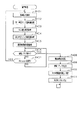
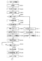
次に、パチンコ機10の電気的構成について、図25のブロック図に基づいて説明する。図25では、電力の供給ラインを二重線矢印で示し、信号ラインを実線矢印で示す。   Next, the electrical configuration of the pachinko machine 10 will be described based on the block diagram of FIG. In FIG. 25, the power supply line is indicated by a double arrow, and the signal line is indicated by a solid arrow.

主制御装置107に設けられた主制御基板311には、主制御回路312と停電監視回路313とが内蔵されている。主制御回路312には、CPU321が搭載されている。CPU321には、当該CPU321により実行される各種の制御プログラムや固定値データを記憶したROM(不揮発性記憶手段)322と、そのROM322内に記憶される制御プログラムの実行に際して各種のデータ等を一時的に記憶するためのメモリであるRAM(揮発性記憶手段)323と、割込回路やタイマ回路、データ入出力回路などの各種回路が内蔵されている。   A main control board 311 provided in the main controller 107 incorporates a main control circuit 312 and a power failure monitoring circuit 313. The main control circuit 312 is equipped with a CPU 321. The CPU 321 temporarily stores various control programs executed by the CPU 321 and ROM (non-volatile storage means) 322 storing fixed value data, and various data when executing the control program stored in the ROM 322. A RAM (volatile storage means) 323, which is a memory for storing data, and various circuits such as an interrupt circuit, a timer circuit, and a data input / output circuit are incorporated.

RAM323は、パチンコ機10の電源の遮断後においても電源及び発射制御装置147に設けられた電源及び発射制御基板331からバックアップ電力(データ記憶保持用電力)が供給されてデータが保持される構成となっている。   The RAM 323 has a configuration in which backup power (data storage holding power) is supplied from the power source and launch control board 331 provided in the power source and launch control device 147 even after the power of the pachinko machine 10 is shut off, and data is retained. It has become.

CPU321には、アドレスバス及びデータバスで構成されるバスラインを介して入出力ポートが接続されている。主制御回路312の入力側には、主制御基板311に設けられた停電監視回路313、払出制御装置146に設けられた払出制御基板332及びその他図示しないスイッチ群などが接続されている。この場合に、停電監視回路313には電源及び発射制御基板331が接続されており、主制御回路312には停電監視回路313を介して電力が供給される。   An input / output port is connected to the CPU 321 via a bus line including an address bus and a data bus. Connected to the input side of the main control circuit 312 are a power failure monitoring circuit 313 provided on the main control board 311, a payout control board 332 provided on the payout control device 146, and other switches not shown. In this case, a power supply and launch control board 331 is connected to the power failure monitoring circuit 313, and power is supplied to the main control circuit 312 via the power failure monitoring circuit 313.

ちなみに、主制御回路312の入力側に接続されるスイッチ群としては、入賞検知センサ325〜328がある。入賞検知センサ325〜328としては、一般入賞口62に入球した遊技球を検知する一般入賞口センサ325と、可変入賞装置63に入球した遊技球を検知するカウントセンサ326と、上作動口64に入球した遊技球を検知する上作動口センサ327と、下作動口65に入球した遊技球を検知する下作動口センサ328とがある。なお、一般入賞口センサ325は、一般入賞口62に対して1対1で対応させて設けられている。これら入賞検知センサ325〜328からの検知結果に基づいて、主制御回路312のCPU321において、各種入賞口62〜65への遊技球の入球の有無が特定される。   Incidentally, as a group of switches connected to the input side of the main control circuit 312, there are winning detection sensors 325 to 328. The winning detection sensors 325 to 328 include a general winning port sensor 325 that detects a game ball that has entered the general winning port 62, a count sensor 326 that detects a game ball that has entered the variable winning device 63, and an upper operating port. There are an upper operation port sensor 327 that detects a game ball that has entered the ball 64 and a lower operation port sensor 328 that detects a game ball that has entered the lower operation port 65. The general prize opening sensor 325 is provided in one-to-one correspondence with the general prize opening 62. Based on the detection results from these winning detection sensors 325 to 328, the CPU 321 of the main control circuit 312 specifies whether or not a game ball has entered the various winning ports 62 to 65.

一方、主制御回路312の出力側には、停電監視回路313、払出制御基板332及び中継端子板333が接続されている。払出制御基板332には、賞球コマンドなどといった各種コマンドが出力される。中継端子板333を介して主制御回路312から音声ランプ制御装置103に設けられた音声ランプ制御基板334に対して各種コマンドなどが出力される。   On the other hand, a power failure monitoring circuit 313, a payout control board 332 and a relay terminal board 333 are connected to the output side of the main control circuit 312. Various commands such as a prize ball command are output to the payout control board 332. Various commands and the like are output from the main control circuit 312 to the sound lamp control board 334 provided in the sound lamp control device 103 via the relay terminal plate 333.

停電監視回路313は、主制御回路312と電源及び発射制御基板331とを中継し、また電源及び発射制御基板331から出力される最大電源である直流安定24ボルトの電源を監視する。   The power failure monitoring circuit 313 relays the main control circuit 312 and the power source and launch control board 331, and monitors the DC stable 24 volt power source that is the maximum power source output from the power source and launch control board 331.

払出制御基板332は、払出装置135により賞球や貸し球の払出制御を行うものである。演算装置であるCPU341は、そのCPU341により実行される制御プログラムや固定値データ等を記憶したROM(不揮発性記憶手段)342と、ワークメモリ等として使用されるRAM(揮発性記憶手段)343とを備えている。   The payout control board 332 performs payout control of prize balls and rental balls by the payout device 135. The CPU 341 which is an arithmetic unit includes a ROM (non-volatile storage means) 342 storing a control program executed by the CPU 341, fixed value data, and the like, and a RAM (volatile storage means) 343 used as a work memory or the like. I have.

払出制御基板332のRAM343は、主制御回路312のRAM323と同様に、パチンコ機10の電源の遮断後においても電源及び発射制御基板331からバックアップ電力(データ記憶保持用電力)が供給されてデータが保持される構成となっている。   Similarly to the RAM 323 of the main control circuit 312, the RAM 343 of the payout control board 332 is supplied with backup power (data storage holding power) from the power supply and the launch control board 331 even after the power supply of the pachinko machine 10 is cut off. It has a configuration to be held.

払出制御基板332のCPU341には、アドレスバス及びデータバスで構成されるバスラインを介して入出力ポートが接続されている。払出制御基板332の入力側には、主制御回路312、電源及び発射制御基板331、及び裏パック基板136が接続されている。ちなみに、裏パック基板136を通じて、球無検知センサ186の検知結果及び球抜きボタン206の操作の有無が払出制御基板332に入力される。また、払出制御基板332の出力側には、主制御回路312及び裏パック基板136が接続されている。   An input / output port is connected to the CPU 341 of the payout control board 332 through a bus line including an address bus and a data bus. A main control circuit 312, a power and launch control board 331, and a backpack board 136 are connected to the input side of the payout control board 332. Incidentally, the detection result of the ball non-detection sensor 186 and the presence / absence of the operation of the ball removal button 206 are input to the payout control board 332 through the back pack board 136. Further, the main control circuit 312 and the back pack board 136 are connected to the output side of the payout control board 332.

電源及び発射制御基板331は、電源部と発射制御部とを備えている。電源部は、二重線矢印で示す経路を通じて、主制御回路312や払出制御基板332等に対して各々に必要な動作電力を供給する。発射制御部は、遊技者による遊技球発射ハンドル84の操作にしたがって遊技球発射機構80の発射制御を担うものであり、遊技球発射機構80は所定の発射条件が整っている場合に駆動される。   The power supply and launch control board 331 includes a power supply unit and a launch control unit. The power supply unit supplies necessary operating power to each of the main control circuit 312 and the payout control board 332 through a path indicated by a double line arrow. The launch control unit is responsible for launch control of the game ball launch mechanism 80 in accordance with the operation of the game ball launch handle 84 by the player, and the game ball launch mechanism 80 is driven when predetermined launch conditions are met. .

また、電源及び発射制御基板331には、バックアップ電源部331aが設けられている。バックアップ電源部331aはコンデンサからなり、パチンコ機10の電源がON状態の場合(外部電源からの電力供給が行われている場合)に充電される。また、パチンコ機10の電源がOFF状態の場合や商用電源における停電発生時といった電源遮断状態(外部電源からの電力供給が遮断されている場合)では、バックアップ電源部331aから放電され主制御回路312のRAM323及び払出制御基板332のRAM343に対してバックアップ電力が供給される。よって、かかる状況であっても、バックアップ電源部331aからバックアップ電力が供給されている間は、各RAM323,343に記憶された情報が消去されることなく記憶保持される。   Further, the power source and launch control board 331 is provided with a backup power source unit 331a. The backup power supply unit 331a includes a capacitor, and is charged when the power of the pachinko machine 10 is in an ON state (when power is supplied from an external power supply). Further, when the power of the pachinko machine 10 is in an OFF state or in a power cut-off state such as when a power failure occurs in a commercial power supply (when power supply from an external power supply is cut off), the main control circuit 312 is discharged from the backup power supply unit 331a. Backup power is supplied to the RAM 323 and the RAM 343 of the payout control board 332. Therefore, even in such a situation, while the backup power is being supplied from the backup power supply unit 331a, the information stored in the RAMs 323 and 343 is stored and held without being erased.

ちなみに、バックアップ電源部331aの容量は比較的大きく確保されており、電源遮断前に各RAM323,343に記憶されていた情報は所定の期間内(例えば、1日や2日)保持される。また、バックアップ電源部331aは、コンデンサに限定されることはなく、バッテリや非充電式電池などであってもよい。非充電式電池の場合、パチンコ機10の電源がON状態の際に電断時用電源手段への蓄電を行う必要はないが、定期的に交換する必要が生じる。   Incidentally, the backup power supply unit 331a has a relatively large capacity, and the information stored in each of the RAMs 323 and 343 before the power supply is cut off is retained within a predetermined period (for example, 1 day or 2 days). Further, the backup power supply unit 331a is not limited to a capacitor, and may be a battery or a non-rechargeable battery. In the case of a non-rechargeable battery, it is not necessary to store power in the power supply means for power interruption when the power of the pachinko machine 10 is ON, but it is necessary to replace it periodically.

音声ランプ制御基板334は、各電飾部175〜177、スピーカ部178、エラー表示部179及び表示制御装置101を制御するものである。演算装置であるCPU351は、そのCPU351により実行される制御プログラムや固定値データ等を記憶したROM352と、ワークメモリ等として使用されるRAM353とを備えている。   The sound lamp control board 334 controls each of the illumination units 175 to 177, the speaker unit 178, the error display unit 179, and the display control device 101. The CPU 351, which is an arithmetic device, includes a ROM 352 that stores a control program executed by the CPU 351, fixed value data, and the like, and a RAM 353 that is used as a work memory or the like.

音声ランプ制御基板334のCPU351にはアドレスバス及びデータバスで構成されるバスラインを介して入出力ポートが接続されている。音声ランプ制御基板334の入力側には中継端子板333に中継されて主制御回路312が接続されており、主制御回路312から出力される各種コマンドに基づいて、各電飾部175〜177、スピーカ部178、エラー表示部179及び表示制御装置101を制御する。表示制御装置101は、音声ランプ制御基板334から入力する表示コマンドに基づいて図柄表示装置71を制御する。   An input / output port is connected to the CPU 351 of the sound lamp control board 334 via a bus line including an address bus and a data bus. A main control circuit 312 is connected to the input side of the sound lamp control board 334 by being relayed to the relay terminal plate 333, and based on various commands output from the main control circuit 312, the lighting units 175 to 177, The speaker unit 178, the error display unit 179, and the display control apparatus 101 are controlled. The display control device 101 controls the symbol display device 71 based on a display command input from the sound lamp control board 334.

次に、主制御回路312のCPU321により実行される各制御処理を図26〜図29のフローチャート等を参照しながら説明する。かかるCPU321の処理としては大別して、電源投入に伴い起動されるメイン処理と、定期的に(本実施形態では2msec周期で)起動されるタイマ割込み処理と、NMI端子(ノンマスカブル端子)への停電信号の入力により起動されるNMI割込み処理とがあり、説明の便宜上、はじめにNMI割込み処理とタイマ割込み処理とを説明し、その後メイン処理を説明する。   Next, each control process executed by the CPU 321 of the main control circuit 312 will be described with reference to the flowcharts of FIGS. The processing of the CPU 321 is roughly divided into main processing that is started when the power is turned on, timer interrupt processing that is started periodically (in this embodiment, at a cycle of 2 msec), and a power failure signal to the NMI terminal (non-maskable terminal). For convenience of explanation, the NMI interrupt process and the timer interrupt process will be described first, and then the main process will be described.

図26は、NMI割込み処理であり、当該処理は、停電の発生等によるパチンコ機10の電源遮断時に実行される。すなわち、停電の発生等によりパチンコ機10の電源が遮断されると、停電信号が停電監視回路313からCPU321のNMI端子に出力され、CPU321は実行中の制御を中断してNMI割込み処理を開始する。NMI割込み処理では、ステップS101にてRAM323に設けられた停電フラグ格納エリアに停電フラグをセットし、本処理を終了する。その後、後述する通常処理にて停電フラグがセットされていることが確認されることで、停電時処理が実行される。   FIG. 26 shows an NMI interrupt process, which is executed when the power of the pachinko machine 10 is shut off due to the occurrence of a power failure or the like. That is, when the power of the pachinko machine 10 is cut off due to the occurrence of a power failure or the like, a power failure signal is output from the power failure monitoring circuit 313 to the NMI terminal of the CPU 321 and the CPU 321 interrupts the control being executed and starts NMI interrupt processing. . In the NMI interrupt processing, the power failure flag is set in the power failure flag storage area provided in the RAM 323 in step S101, and this processing is terminated. Thereafter, when it is confirmed that the power failure flag is set in the normal processing described later, the power failure processing is executed.

次に、タイマ割込み処理について図27のフローチャートを用いて説明する。   Next, timer interrupt processing will be described with reference to the flowchart of FIG.

先ずステップS201では、各種スイッチや払出制御基板332などからの信号読み込み処理を実行する。ここで、信号読み込み処理では、一般入賞口センサ325、カウントセンサ326、上作動口センサ327及び下作動口センサ328から遊技球を検知している旨の検知結果を入力しているか否かを特定し、その特定結果に基づいて賞球コマンドのセットを行う処理を実行する。具体的には、一般入賞口センサ325の検知結果に基づいて一般入賞口62への遊技球の入球を特定した場合には10個賞球コマンドをセットする。また、カウントセンサ326の検知結果に基づいて可変入賞装置63への遊技球の入球を特定した場合には15個賞球コマンドをセットする。また、上作動口センサ327の検知結果に基づいて上作動口64への遊技球の入球を特定した場合には3個賞球コマンドをセットする。また、下作動口センサ328の検知結果に基づいて下作動口65への遊技球の入球を特定した場合には4個賞球コマンドをセットする。ここで、セットされた賞球コマンドは、後述する外部出力処理にて払出制御基板332に出力される。   First, in step S201, signal reading processing from various switches and the payout control board 332 is executed. Here, in the signal reading process, it is specified whether or not a detection result indicating that a game ball is detected is input from the general winning opening sensor 325, the count sensor 326, the upper operation port sensor 327, and the lower operation port sensor 328. Then, a process for setting a prize ball command is executed based on the specified result. Specifically, when a game ball is entered into the general prize opening 62 based on the detection result of the general prize opening sensor 325, ten prize ball commands are set. Further, when a game ball is entered into the variable winning device 63 based on the detection result of the count sensor 326, 15 prize ball commands are set. Further, when a game ball entering the upper operation port 64 is specified based on the detection result of the upper operation port sensor 327, three prize ball commands are set. In addition, when a game ball enters the lower operation port 65 based on the detection result of the lower operation port sensor 328, four prize ball commands are set. Here, the set prize ball command is output to the payout control board 332 in an external output process described later.

その後、ステップS202では、始動入賞処理を実行する。始動入賞処理では、上作動口センサ327及び下作動口センサ328から入力した検知結果に基づいて、遊技球が上作動口64又は下作動口65に入球したか否かを判定する。そして、遊技球が上作動口64又は下作動口65に入球している場合には、第1特定ランプ部73及び図柄表示装置71の作動保留球数が上限値未満であることを条件として、その入球に対して大当たりを発生させるか否かの指標となるカウンタ値のRAM323への格納処理を実行する。当該カウンタ値が大当たりの発生に対応した値である場合には、その入球に対応した遊技回において大当たりが発生することとなる。つまり、始動入賞処理において、大当たりといった特別遊技状態への移行抽選機能(移行判定手段)が果たされる。   Thereafter, in step S202, a start winning process is executed. In the start winning process, it is determined whether or not a game ball has entered the upper operating port 64 or the lower operating port 65 based on the detection results input from the upper operating port sensor 327 and the lower operating port sensor 328. And when a game ball is entering the upper operation port 64 or the lower operation port 65, the number of operation reservation balls of the 1st specific lamp part 73 and the symbol display apparatus 71 is less than an upper limit. Then, a process of storing in the RAM 323 a counter value serving as an index as to whether or not to generate a big hit for the incoming ball is executed. If the counter value is a value corresponding to the occurrence of the jackpot, the jackpot is generated in the game times corresponding to the entry. That is, in the start winning process, a lottery function (transition determination means) for transitioning to a special gaming state such as a big win is performed.

始動入賞処理の後、CPU321は本タイマ割込み処理を一旦終了する。なお、タイマ割込み処理において、大当たりを発生させるか否かの指標となるカウンタ値を更新する処理なども実行するようにしてもよい。   After the start winning process, the CPU 321 once ends the timer interrupt process. In the timer interrupt process, a process of updating a counter value serving as an index as to whether or not to generate a jackpot may be executed.

次に、電源投入時のリセットに伴い起動されるメイン処理について、図28のフローチャートを用いて説明する。   Next, the main process started by the reset at the time of power-on is demonstrated using the flowchart of FIG.

先ずステップS301では、電源投入に伴う初期設定処理を実行する。具体的には、従側の制御基板(払出制御基板332等)が動作可能な状態になるのを待つために例えば1秒程度、ウェイト処理を実行する。続くステップS302では、RAM323のアクセスを許可する。   First, in step S301, an initial setting process associated with power-on is executed. Specifically, a wait process is executed, for example, for about 1 second in order to wait for the slave control board (such as the payout control board 332) to be operable. In the subsequent step S302, access to the RAM 323 is permitted.

その後、ステップS303では、電源及び発射制御装置147に設けたRAM消去スイッチ149aがオンされているか否かを判定し、続くステップS304ではRAM323の停電フラグ格納バッファに停電フラグが格納されているか否かを判定する。また、ステップS305ではRAM判定値を算出し、続くステップS306では、そのRAM判定値が電源遮断時に保存したRAM判定値と一致するか否か、すなわち記憶保持されたデータの有効性を判定する。RAM判定値は、例えばRAM323の作業領域アドレスにおけるチェックサム値である。なお、RAM323の所定のエリアに書き込まれたキーワードが正しく保存されているか否かにより記憶保持されたデータの有効性を判断することも可能である。   Thereafter, in step S303, it is determined whether or not the RAM erase switch 149a provided in the power supply and launch control device 147 is turned on. In subsequent step S304, whether or not the power failure flag is stored in the power failure flag storage buffer of the RAM 323 is determined. Determine. In step S305, a RAM determination value is calculated. In subsequent step S306, it is determined whether or not the RAM determination value matches the RAM determination value stored when the power is turned off, that is, the validity of the stored data. The RAM determination value is a checksum value at the work area address of the RAM 323, for example. It is also possible to determine the validity of the data stored and held based on whether or not the keywords written in a predetermined area of the RAM 323 are correctly stored.

上述したように、本パチンコ機10では、例えばホールの営業開始時など、電源投入時にRAMデータを初期化する場合にはRAM消去スイッチ149aを押しながら電源が投入される。従って、RAM消去スイッチ149aが押されていれば、ステップS309〜S311の処理に移行する。また、電源遮断の発生情報が設定されていない場合や、RAM判定値(チェックサム値等)により記憶保持されたデータの異常が確認された場合も同様にステップS309〜S311の処理に移行する。   As described above, in the pachinko machine 10, for example, when RAM data is initialized when the power is turned on, such as at the start of business in a hall, the power is turned on while pressing the RAM erase switch 149a. Therefore, if the RAM erase switch 149a is pressed, the process proceeds to steps S309 to S311. Similarly, when the information on occurrence of power shutdown is not set, or when an abnormality of data stored and held is confirmed by the RAM determination value (checksum value or the like), the process proceeds to steps S309 to S311.

ステップS309では、従側の制御基板となる払出制御基板332等を初期化するために、払出初期化コマンド等を出力する。続くステップS310ではRAM323の使用領域を0にクリアし、ステップS311ではRAM323の初期化処理を実行する。その後、ステップS312にて割込み許可を設定し、後述する通常処理に移行する。   In step S309, a payout initialization command or the like is output in order to initialize the payout control board 332 or the like serving as the slave control board. In subsequent step S310, the used area of the RAM 323 is cleared to 0, and in step S311, initialization processing of the RAM 323 is executed. Thereafter, interrupt permission is set in step S312, and the routine proceeds to normal processing described later.

一方、RAM消去スイッチ149aが押されていない場合には、停電フラグが格納されていること、及びRAM判定値(チェックサム値等)が正常であることを条件に、ステップS307に進む。ステップS307では、停電フラグ格納バッファに格納されている停電フラグをクリアし、ステップS308にて従側の制御基板を電源遮断前の遊技状態に復帰させるための復電コマンドを出力する。その後、ステップS312にて割込み許可を設定し、後述する通常処理に移行する。これにより、電源遮断前の状態に復帰する。   On the other hand, if the RAM erase switch 149a has not been pressed, the process proceeds to step S307 on condition that the power failure flag is stored and the RAM determination value (checksum value etc.) is normal. In step S307, the power failure flag stored in the power failure flag storage buffer is cleared, and in step S308, a power recovery command for returning the slave control board to the gaming state before power-off is output. Thereafter, interrupt permission is set in step S312, and the routine proceeds to normal processing described later. Thereby, it returns to the state before power-off.

次に、通常処理について、図29のフローチャートを用いて説明する。この通常処理では遊技の主要な処理が実行される。   Next, normal processing will be described with reference to the flowchart of FIG. In this normal process, the main process of the game is executed.

通常処理において、ステップS401では、前回の処理で更新されたコマンド等の出力データを従側の各制御基板に出力する。具体的には、上述した信号読み込み処理にてセットされた賞球コマンドを払出制御基板332に対して出力する。また、図柄表示装置71による第1図柄の変動表示に際して停止図柄コマンド、変動態様コマンド等を音声ランプ制御基板334に出力する。   In the normal process, in step S401, output data such as a command updated in the previous process is output to each control board on the slave side. Specifically, the prize ball command set in the signal reading process described above is output to the payout control board 332. Further, a stop symbol command, a variation mode command, and the like are output to the sound lamp control board 334 when the symbol display device 71 displays the variation of the first symbol.

続くステップS402では、第1特定ランプ部73に表示される色の切り替えを行うための第1特定ランプ部制御処理を実行する。第1特定ランプ部制御処理では、大当たり判定や第1特定ランプ部73に配設されたLEDランプの光源スイッチのオンオフ制御などが行われる。そして、第1特定ランプ制御処理では、始動入賞処理にて格納されたカウンタ値に基づいて大当たりを発生させると判定した場合、遊技状態を大当たり状態に移行させる。つまり、第1特定ランプ制御処理において、特別遊技状態への移行機能(移行手段)が果たされる。なお、第1特定ランプ部制御処理において、図柄表示装置71による第1図柄の変動表示の設定も行われる。   In a succeeding step S402, a first specific lamp unit control process for switching the color displayed on the first specific lamp unit 73 is executed. In the first specific lamp unit control process, jackpot determination, on / off control of a light source switch of an LED lamp disposed in the first specific lamp unit 73, and the like are performed. Then, in the first specific lamp control process, when it is determined that the jackpot is generated based on the counter value stored in the start winning process, the gaming state is shifted to the jackpot state. That is, in the first specific lamp control process, a function for shifting to the special gaming state (transition means) is performed. In the first specific lamp unit control process, the variable display of the first symbol by the symbol display device 71 is also set.

第1特定ランプ部制御処理の後は、ステップS403にて大入賞口開閉処理を実行する。大入賞口開閉処理では、大当たり状態である場合において可変入賞装置63の大入賞口を開放又は閉鎖する。すなわち、大当たり状態のラウンド毎に大入賞口を開放し、大入賞口の最大開放時間が経過したか、又は大入賞口に遊技球が規定数だけ入賞したかを判定する。この規定数だけ入賞したか否かの判定は、上述した大入賞口用カウンタを確認することにより行われる。そして、これら何れかの条件が成立すると大入賞口を閉鎖する。つまり、大入賞口開閉処理において、特別遊技状態の進行機能(進行手段)が果たされる。   After the first specific lamp unit control process, a special winning opening opening / closing process is executed in step S403. In the big prize opening / closing process, the big prize opening of the variable prize winning device 63 is opened or closed in the case of a big hit state. That is, it is determined whether the big winning opening is opened for each round of the big hit state, and whether the maximum opening time of the big winning opening has elapsed or whether a predetermined number of game balls have been won in the big winning opening. The determination as to whether or not the prescribed number has been won is made by confirming the above-described counter for the big prize opening. When either of these conditions is satisfied, the special winning opening is closed. In other words, the special game state progression function (progress means) is performed in the special prize opening / closing process.

その後、ステップS404では、第2特定ランプ部74に表示される色の切り替え処理を行うための第2特定ランプ部制御処理を実行する。第2特定ランプ制御処理では、ゲート保留球数が1以上であることを条件に第2特定ランプ部74における表示色の切り換えを開始する。この際、表示色の切り換え時間も設定する。そして、下作動口65に付随する電動役物65aを所定時間開放する場合には、第2特定ランプ部74において所定の色の停止表示が行われる。   Thereafter, in step S404, a second specific lamp unit control process for switching the color displayed on the second specific lamp unit 74 is executed. In the second specific lamp control process, the switching of the display color in the second specific lamp unit 74 is started on the condition that the number of retained gate balls is 1 or more. At this time, the display color switching time is also set. Then, when the electric accessory 65 a attached to the lower working port 65 is opened for a predetermined time, a stop display of a predetermined color is performed in the second specific lamp unit 74.

ステップS404の後は、ステップS405にて、遊技球発射制御処理を実行する。遊技球発射制御処理では、電源及び発射制御基板331の発射制御部から発射許可信号を入力していることを条件として、所定期間(例えば、0.6sec)に1回、遊技球発射機構80のソレノイド81を励磁する。これにより、発射レール82上にある遊技球が遊技領域に向けて打ち出される。   After step S404, a game ball launch control process is executed in step S405. In the game ball launch control process, the game ball launch mechanism 80 of the game ball launch mechanism 80 is once in a predetermined period (for example, 0.6 sec) on condition that a launch permission signal is input from the launch control unit of the power source and launch control board 331. The solenoid 81 is excited. Thereby, the game ball on the launch rail 82 is launched toward the game area.

続くステップS406では、RAM323内に設けられた停電フラグ格納バッファに停電フラグが格納されているか否かを判定する。停電フラグが格納されていない場合は、繰り返し実行される複数の処理の最後の処理が終了したこととなるので、ステップS407にて次の通常処理の実行タイミングに至ったか否か、すなわち前回の通常処理の開始から所定時間(本実施形態では4msec)が経過したか否かを判定する。所定時間が経過していない場合には、ステップS406に戻り、所定時間が経過している場合には、ステップS401に戻る。   In a succeeding step S406, it is determined whether or not a power failure flag is stored in a power failure flag storage buffer provided in the RAM 323. If the power failure flag is not stored, the last process of the plurality of processes that are repeatedly executed is completed, so whether or not the execution timing of the next normal process is reached in step S407, that is, the previous normal process It is determined whether a predetermined time (4 msec in this embodiment) has elapsed since the start of the process. If the predetermined time has not elapsed, the process returns to step S406, and if the predetermined time has elapsed, the process returns to step S401.

一方、ステップ406にて、停電フラグが格納されている場合は、電源遮断が発生したことになるので、ステップS408以降の停電時処理を実行する。つまり、ステップS408では、タイマ割込み処理の発生を禁止する。続くステップS409では、電源が遮断されたことを示す停電コマンドを他の制御基板に対して出力する。そして、ステップS410にてRAM判定値を算出、保存し、ステップS411にてRAM323のアクセスを禁止した後に、電源が完全に遮断して処理が実行できなくなるまで無限ループを継続する。なお、電源が完全に遮断された後も、電源及び発射制御基板331のバックアップ電源部331aからバックアップ電力が供給されるため、電源遮断前にRAM323に記憶されていた情報はそのままの状態で所定の期間内(例えば、1日や2日)保持される。   On the other hand, if the power failure flag is stored in step 406, it means that the power supply has been cut off, and therefore, the power failure processing after step S408 is executed. That is, in step S408, the generation of timer interrupt processing is prohibited. In subsequent step S409, a power failure command indicating that the power supply has been shut off is output to another control board. In step S410, the RAM determination value is calculated and stored, and after the access to the RAM 323 is prohibited in step S411, the infinite loop is continued until the power supply is completely shut down and the process cannot be executed. Even after the power supply is completely shut down, the backup power is supplied from the power source and the backup power supply unit 331a of the launch control board 331. Therefore, the information stored in the RAM 323 before the power is shut off is left in a predetermined state. It is held within a period (for example, 1 day or 2 days).

次に、払出制御基板332のCPU341により実行される各制御処理を図30〜図33のフローチャートを参照しながら説明する。かかるCPU341の処理としては大別して、主制御回路312のCPU321からのコマンドの入力により起動される入力時割込み処理と、電源投入に伴い起動されるメイン処理と、定期的に(本実施の形態では2msec周期で)起動されるタイマ割込み処理とがあり、説明の便宜上、はじめに入力時割込み処理を説明し、その後、メイン処理、タイマ割込み処理の順で説明する。   Next, each control process executed by the CPU 341 of the payout control board 332 will be described with reference to the flowcharts of FIGS. The processing of the CPU 341 can be broadly divided into input interrupt processing activated by the input of a command from the CPU 321 of the main control circuit 312, main processing activated upon power-on, and periodically (in this embodiment). There is a timer interrupt process activated at a cycle of 2 msec). For convenience of explanation, the interrupt process at the time of input will be described first, and then the main process and the timer interrupt process will be described in this order.

入力時割込み処理は、主制御回路312のCPU321からコマンドを入力した場合に後述する他の処理を中断して実行される。入力時割込み処理では、図30のフローチャートに示すように、ステップS501にて主制御回路312のCPU321からのコマンドをRAM343のコマンド格納バッファに記憶し、その後、ステップS502にてRAM343に設けられたコマンド入力フラグ格納バッファにコマンド入力フラグを格納し、本処理を終了する。   The input interrupt process is executed by interrupting other processes described later when a command is input from the CPU 321 of the main control circuit 312. In the interrupt process at the time of input, as shown in the flowchart of FIG. 30, the command from the CPU 321 of the main control circuit 312 is stored in the command storage buffer of the RAM 343 in step S501, and then the command provided in the RAM 343 in step S502. The command input flag is stored in the input flag storage buffer, and this process is terminated.

次に、払出制御基板332のCPU341に実行されるメイン処理を、図31のフローチャートを用いて説明する。このメイン処理は、電源投入時のリセットに伴い起動される。   Next, main processing executed by the CPU 341 of the payout control board 332 will be described with reference to the flowchart of FIG. This main process is started upon reset at power-on.

まず、ステップS601では、電源投入に伴う初期設定処理を実行する。具体的には、割込みモードを設定する。そして、ステップS602に進んでRAMアクセスを許可すると共に、ステップS603で外部割込みベクタの設定を行う。   First, in step S601, an initial setting process associated with power-on is executed. Specifically, the interrupt mode is set. In step S602, RAM access is permitted and an external interrupt vector is set in step S603.

その後、ステップS604では、RAM343の停電フラグ格納バッファに停電フラグが格納されているか否かを判定する。また、ステップS605ではRAM判定値を算出し、続くステップS606では、そのRAM判定値が電源遮断時に保存したRAM判定値と一致するか否か、すなわち記憶保持されたデータの有効性を判定する。RAM判定値は、例えばRAM343の作業領域アドレスにおけるチェックサム値である。なお、RAM343の所定のエリアに書き込まれたキーワードが正しく保存されているか否かにより記憶保持されたデータの有効性を判断することも可能である。   Thereafter, in step S604, it is determined whether or not a power failure flag is stored in the power failure flag storage buffer of the RAM 343. In step S605, a RAM determination value is calculated. In subsequent step S606, it is determined whether or not the RAM determination value matches the RAM determination value stored when the power is turned off, that is, the validity of the stored data. The RAM determination value is a checksum value at a work area address in the RAM 343, for example. It is also possible to determine the validity of the stored data based on whether or not the keywords written in a predetermined area of the RAM 343 are correctly stored.

停電フラグが格納されていない場合や、RAM判定値(チェックサム値等)により記憶保持されたデータの異常が確認された場合はRAM343の初期化処理(ステップS611〜S613)に移行する。つまり、ステップS611ではRAM343の全領域を0にクリアし、続くステップS612ではRAM343の初期化処理を実行する。また、ステップS613ではCPU周辺デバイスの初期設定を行う。   When the power failure flag is not stored, or when abnormality of data stored and held is confirmed by the RAM determination value (check sum value or the like), the process proceeds to initialization processing (steps S611 to S613) of the RAM 343. That is, in step S611, the entire area of the RAM 343 is cleared to 0, and in the subsequent step S612, initialization processing of the RAM 343 is executed. In step S613, the CPU peripheral device is initialized.

一方、停電フラグが格納されており、さらにRAM判定値(チェックサム値等)が正常である場合は、復電時の処理(停電による電源遮断後の復旧時の処理)を実行する。つまり、ステップS607にて停電フラグをクリアすると共に、ステップS608にて賞球の払出を許可する払出許可フラグをクリアする。また、ステップS609ではCPU周辺デバイスの初期設定を行う。なお、RAM判定値は、例えばRAM343の作業領域アドレスにおけるチェックサム値である。   On the other hand, when the power failure flag is stored and the RAM determination value (checksum value or the like) is normal, processing at power recovery (processing at power recovery after power failure due to power failure) is executed. That is, in step S607, the power failure flag is cleared, and in step S608, the payout permission flag for permitting the payout of prize balls is cleared. In step S609, the CPU peripheral device is initialized. The RAM determination value is, for example, a checksum value at a work area address in the RAM 343.

ステップS609又はステップS613の処理の後は、ステップS610にて割込みを許可し、ステップS614にてRAM343の停電フラグ格納バッファに停電フラグが格納されているか否かを判定し、停電フラグが格納されていなければ、停電フラグが格納されるまで待機する。   After the process of step S609 or step S613, an interrupt is permitted in step S610, and it is determined in step S614 whether or not a power failure flag is stored in the power failure flag storage buffer of the RAM 343, and the power failure flag is stored. If not, it waits until the power failure flag is stored.

一方、停電フラグが格納されている場合には、停電が発生したことになるので、停電時処理としてステップS615移行の処理を実行する。停電時処理では、先ずステップS615にて各割込み処理の発生を禁止する。その後、ステップS616にてRAM判定値を算出、保存し、ステップS617にてRAM343のアクセスを禁止して、電源が完全に遮断して処理が実行できなくなるまで無限ループを継続する。なお、電源が完全に遮断された後も、電源及び発射制御基板331からRAM343のデータ記憶保持用電力が供給されるため、電源遮断前にRAM343に記憶されていた情報は所定の期間内(例えば、1日や2日)保持される。   On the other hand, if the power failure flag is stored, it means that a power failure has occurred, and therefore the process of step S615 is executed as a power failure process. In the power failure process, first, in step S615, the generation of each interrupt process is prohibited. Thereafter, the RAM determination value is calculated and stored in step S616, and access to the RAM 343 is prohibited in step S617, and the infinite loop is continued until the power supply is completely shut down and the process cannot be executed. Even after the power supply is completely shut off, the power for holding data storage in the RAM 343 is supplied from the power supply and launch control board 331. Therefore, the information stored in the RAM 343 before the power supply is shut off within a predetermined period (for example, 1 or 2 days).

ここで、本メイン処理では、ステップS601〜ステップS613の通常時における一連の処理の終了後に、停電フラグが格納されているか否か(電源遮断が発生したか否か)を判定しているので、各処理の途中の状態で停電時処理が実行されることがない。これにより、電源遮断発生時においてRAM343に記憶するデータ量を極力少なくすることができ、さらには電源遮断前の状態に復帰する場合には、処理の途中から開始する必要はなく、払出制御基板332の処理の負担を軽減することができる。   Here, in this main process, it is determined whether or not a power failure flag is stored (whether or not a power interruption has occurred) after the end of a series of processes at the normal times of steps S601 to S613. There is no power outage process in the middle of each process. As a result, the amount of data stored in the RAM 343 can be reduced as much as possible when the power interruption occurs, and further, when returning to the state before the power interruption, it is not necessary to start from the middle of the processing, and the payout control board 332 The burden of processing can be reduced.

次に、払出制御基板332のCPU341により例えば2msec毎に実行されるタイマ割込み処理について、図32のフローチャートを用いて説明する。   Next, timer interrupt processing executed by the CPU 341 of the payout control board 332, for example, every 2 msec will be described with reference to the flowchart of FIG.

先ずステップS701では、主制御回路312のCPU321から入力したコマンドの判定を行うコマンド判定処理を実行する。このコマンド判定処理では、図33に示すように、ステップS801にて、RAM343のコマンド入力フラグ格納バッファにコマンド入力フラグが格納されているか否かを判定する。コマンド入力フラグが格納されていない場合は、新たなコマンドが主制御回路312のCPU321から出力されていないので、そのまま本処理を終了する。一方、コマンド入力フラグが格納されていた場合は、ステップS802にてコマンド読出し処理を実行する。コマンド読出し処理では、入力したコマンドをRAM343のコマンドバッファから読出し、さらにコマンド入力フラグをクリアする。   First, in step S701, command determination processing for determining a command input from the CPU 321 of the main control circuit 312 is executed. In this command determination process, as shown in FIG. 33, in step S801, it is determined whether or not a command input flag is stored in the command input flag storage buffer of the RAM 343. If no command input flag is stored, a new command has not been output from the CPU 321 of the main control circuit 312, so this process is terminated. On the other hand, if the command input flag is stored, command read processing is executed in step S802. In the command read process, the input command is read from the command buffer of the RAM 343, and the command input flag is cleared.

その後、読み出されたコマンドの種類を、ステップS803、ステップS805、ステップS810及びステップS811の各処理にて判定し、各コマンドに対応した処理を実行する。つまり、ステップS803では、停電コマンドであるか否かを判定し、当該コマンドである場合には、ステップS804にてRAM343の停電フラグ格納バッファに停電フラグを格納して、本処理を終了する。   Thereafter, the type of the read command is determined in each process of step S803, step S805, step S810, and step S811, and the process corresponding to each command is executed. That is, in step S803, it is determined whether or not the command is a power failure command. If the command is the command, the power failure flag is stored in the power failure flag storage buffer of the RAM 343 in step S804, and the process is terminated.

ステップS805では、払出初期化コマンドであるか否かを判定し、当該コマンドである場合には、電源投入時に主制御回路312のCPU321からRAM343の初期化が指示されていることになるので、ステップS806〜ステップS809の処理を実行した後に本処理を終了する。ステップS806では、RAM343に設けられた払出許可フラグ格納バッファに払出許可フラグが格納されているか否かを判定し、当該フラグが格納されていない場合は、ステップS807にてRAM343の作業領域を0にクリアし、さらにステップS808にてRAM343の初期値を設定する。その後、ステップS809にて払出許可フラグを格納することで、賞球の払出が許可される。   In step S805, it is determined whether the command is a payout initialization command. If the command is the command, initialization of the RAM 343 is instructed from the CPU 321 of the main control circuit 312 when the power is turned on. After executing the processing of S806 to Step S809, this processing is terminated. In step S806, it is determined whether or not a payout permission flag is stored in the payout permission flag storage buffer provided in the RAM 343. If the flag is not stored, the work area of the RAM 343 is set to 0 in step S807. In step S808, the initial value of the RAM 343 is set. Thereafter, by storing a payout permission flag in step S809, payout of prize balls is permitted.

なお、ステップS806において払出許可フラグが格納されている場合は、ステップS807及びステップS808の処理を行うことなく本処理を終了する。かかる構成とすることにより、RAM消去スイッチ149aが押されていないにも関わらずノイズなどの原因で払出初期化コマンドの入力を認識したとしても、その際に残っている賞球が遊技者に払い出されることなく消去されることを防止できる。   If the payout permission flag is stored in step S806, the process ends without performing the processes in steps S807 and S808. With this configuration, even if the input of the payout initialization command is recognized due to noise or the like even though the RAM erase switch 149a is not pressed, the remaining prize ball is paid out to the player. Can be prevented without being erased.

ステップS810では、復電コマンドであるか否かを判定し、当該コマンドである場合には、払出制御基板332が停電による電源遮断の前の状態に復帰するので、ステップS809にて払出許可フラグを格納した後に本処理を終了する。かかる構成とすることにより、電源遮断前に賞球が残っていた場合に当該賞球を即座に払い出すことができる。   In step S810, it is determined whether the command is a power recovery command. If the command is the command, since the payout control board 332 returns to the state before the power cut-off due to a power failure, the payout permission flag is set in step S809. After storing, this process is terminated. With such a configuration, when a prize ball remains before the power is turned off, the prize ball can be paid out immediately.

ステップS811では、賞球コマンドである否かを判定し、当該コマンドである場合には、ステップS812にて賞球コマンドに対応した賞球個数を総賞球個数に加算した後に、ステップS809にて払出許可フラグを格納し本処理を終了する。   In step S811, it is determined whether or not the command is a prize ball command. If it is the command, the number of prize balls corresponding to the prize ball command is added to the total number of prize balls in step S812, and then in step S809. The payout permission flag is stored, and this process ends.

タイマ割込み処理(図32)の説明に戻り、コマンド判定処理を実行した後は、ステップS702にて払出許可フラグが格納されているか否かを判定する。払出許可フラグが格納されていない場合は、そのまま本処理を終了する。一方、払出許可フラグが格納されている場合は、ステップS703にて状態復帰スイッチ148aをチェックして、状態復帰動作開始と判定した場合に状態復帰動作を実行する。   Returning to the description of the timer interrupt process (FIG. 32), after executing the command determination process, it is determined in step S702 whether a payout permission flag is stored. If the payout permission flag is not stored, this processing is terminated as it is. On the other hand, if the payout permission flag is stored, the state return switch 148a is checked in step S703, and if it is determined that the state return operation has started, the state return operation is executed.

また、ステップS704では、タンク球の状態の変化に応じてタンク球無し状態又はタンク球無し解除状態の設定を実行する。すなわち、球無検知センサ186の検知結果によりタンク132の球無状態を判定し、球無状態であると判定した場合には球無状態の設定を実行し、球無状態でなくなった場合には球無状態の設定を解除する。   In step S704, setting of a tank ball absence state or a tank ball absence release state is executed according to a change in the state of the tank ball. That is, the absence of a sphere in the tank 132 is determined based on the detection result of the no-sphere detection sensor 186. If it is determined that there is no sphere, the setting of the no-sphere state is executed. Cancels the setting of no ball.

本パチンコ機10では、払出制御装置146のRAM343に期間計測手段としてカウンタエリアが設けられており、球無検知センサ186から球無状態である旨の検知結果を入力している場合、カウンタエリアにてその入力継続期間が計測される。そして、入力継続期間が1secに達した時点で払出装置135の払出速度をそれまでよりも遅い低速周期に変更する。例えば、通常周期は60msecに1個の遊技球を払い出す周期であり、低速周期は1.2secに1個の遊技球を払い出す周期である。また、低速周期で遊技球の払出を実行している状況であって、上記入力継続期間が10secに達した場合には払出装置135が停止されるとともにその状態が維持されるように規制される。ステップS704では、上記入力継続期間が1secに達した時点で、RAM343に低速設定フラグを格納するとともに、上記入力継続期間が10secに達した時点で、賞球の払出不可状態の設定を行う。なお、期間計測手段としてカウンタエリアに代えて、リアルタイマを設けてもよい。   In the pachinko machine 10, a counter area is provided as a period measuring means in the RAM 343 of the payout control device 146, and when a detection result indicating that there is no ball is input from the ball no detection sensor 186, The input duration is measured. Then, when the input continuation period reaches 1 sec, the payout speed of the payout device 135 is changed to a lower speed cycle than before. For example, the normal period is a period for paying out one game ball every 60 msec, and the low speed period is a period for paying out one game ball every 1.2 sec. Further, in a situation where game balls are paid out at a low speed cycle, when the input continuation period reaches 10 sec, the payout device 135 is stopped and restricted so that the state is maintained. . In step S704, a low speed setting flag is stored in the RAM 343 when the input continuation period reaches 1 sec. When the input continuation period reaches 10 sec, a prize ball payout disabled state is set. Note that a real timer may be provided as a period measuring means instead of the counter area.

また、払出装置135の払出速度が低速周期である状況及び遊技球の払出が停止されている状況において球無状態である旨の検知結果が途切れることで、これら球無状態の設定が解除される。これにより、上記低速状態及び上記賞球の払出不許可状態が解除される。   In addition, in the situation where the payout speed of the payout device 135 is a low-speed cycle and the situation where the payout of the game ball is stopped, the detection result indicating that there is no ball is interrupted, and the setting of these ball-free states is cancelled. . As a result, the low-speed state and the prize ball disapproval state are canceled.

ここで、球無状態となったことに基づいて払出装置135の払出動作を停止させることで、球無状態であるにも関わらず、払出装置135が払出動作を続けてしまうことが防止される。   Here, by stopping the payout operation of the payout device 135 based on the absence of the ball, it is possible to prevent the payout device 135 from continuing the payout operation despite the absence of the ball. .

また、払出装置135の払出動作を停止させる前段階で払出速度を低速周期に変更させたことにより、以下の効果が得られる。つまり、大当たり状態などのように多数の遊技球が短時間で払い出される場合、タンク132から上下通路ユニット134側への遊技球の流入が遅れることがある。この場合に、払出速度を低速周期に変更させない構成を想定すると、球無検知センサ186よりも下流側にある遊技球の払出が即座に完了してしまい、実際には大当たり状態に対する賞球数の情報が未だ残っているにも関わらず、遊技球の払出が停止されてしまう。そうすると、遊技者は大当たり状態における遊技球の払出が完了したと勘違いし、パチンコ機10から離れてしまう可能性がある。これに対して、上記のように払出速度を低速周期に変更させることで、上記状況となった場合には球無検知センサ186よりも下流側にある遊技球がゆっくりと払い出され、その間にタンク132から上下通路ユニット134側へ遊技球が流入する可能性が高まる。よって、上記のような不都合が発生する可能性が低減される。   In addition, the following effects can be obtained by changing the payout speed to the low speed cycle at the stage before the payout operation of the payout device 135 is stopped. That is, when a large number of game balls are paid out in a short time, such as in a big hit state, the flow of game balls from the tank 132 to the vertical passage unit 134 side may be delayed. In this case, assuming a configuration in which the payout speed is not changed to a low speed cycle, the payout of the game ball located downstream of the ball non-detection sensor 186 is immediately completed. Even though the information still remains, the payout of game balls is stopped. If it does so, a player may misunderstand that the payout of the game ball in the big hit state is completed, and there is a possibility that the player will be separated from the pachinko machine 10. On the other hand, by changing the payout speed to a low speed cycle as described above, the game ball on the downstream side of the ball non-detection sensor 186 is slowly paid out in the above situation. The possibility that a game ball flows from the tank 132 to the upper and lower passage unit 134 side is increased. Therefore, the possibility that the above inconvenience occurs is reduced.

ちなみに、遊技球の払出を通常周期である60msecで1sec継続した場合、16個の遊技球が払い出される。また、遊技球の払出を低速周期である1.2secで9sec継続した場合、7個の遊技球が払い出される。つまり、球無検知センサ186にて球無状態であることが検知されてから払出装置135の払出動作が停止されるまでの間に23個の遊技球が払い出されることとなる。これに対して、既に説明したように、残存遊技球数が29個であり、球無検知センサ186と払出装置135との間には少なくとも29個の遊技球が存在することとなる。したがって、球無状態となり払出装置135が停止したとしても、球無検知センサ186と払出装置135との間には遊技球が存在することとなる。   Incidentally, when the game balls are paid out for 1 sec at 60 msec, which is the normal cycle, 16 game balls are paid out. In addition, when the game balls are continuously dispensed for 9 seconds at the low speed of 1.2 seconds, seven game balls are paid out. In other words, 23 gaming balls are paid out after the ball non-detection sensor 186 detects that there is no ball, until the payout operation of the payout device 135 is stopped. On the other hand, as already described, the number of remaining game balls is 29, and at least 29 game balls exist between the ball non-detection sensor 186 and the payout device 135. Therefore, even if the ball is in a state of being absent and the payout device 135 is stopped, a game ball exists between the ball no detection sensor 186 and the payout device 135.

例えば、球無状態となり払出装置135が停止した場合に、球無検知センサ186と払出装置135との間に遊技球が存在しない構成を想定すると、払出装置135が停止した後にタンク132から払出装置135へ流入してくる遊技球は、タンク132の位置から払出装置135の回転体195までの距離分加速されながら流下し、その勢いのまま回転体195に衝突することとなる。そうすると回転体195の破損などが懸念される。これに対して、本パチンコ機10では球無検知センサ186と払出装置135との間に遊技球が存在するため、上記のような回転体195の破損の発生が抑制される。   For example, when it is assumed that there is no gaming ball between the ball non-detection sensor 186 and the payout device 135 when the payout device 135 stops due to the absence of a ball, the payout device from the tank 132 after the payout device 135 stops is assumed. The game ball flowing into 135 flows down while being accelerated by the distance from the position of the tank 132 to the rotating body 195 of the payout device 135 and collides with the rotating body 195 with its momentum. Then, there is a concern that the rotating body 195 is damaged. On the other hand, in this pachinko machine 10, since a game ball exists between the ball non-detection sensor 186 and the payout device 135, the occurrence of breakage of the rotating body 195 as described above is suppressed.

タイマ割込み処理(図32)の説明に戻り、ステップS704の後は、ステップS705にて、報知する状態の有無を判定し、報知する状態が有る場合には払出制御装置242に設けた7セグメントLEDにより報知する。   Returning to the description of the timer interrupt process (FIG. 32), after step S704, in step S705, the presence / absence of a notification state is determined, and if there is a notification state, a 7-segment LED provided in the payout control device 242. To inform.

ステップS706〜S709では、賞球払出の処理を実行する。先ずステップS706では、球抜きボタン206が操作されているか否かを判定する。球抜きボタン206が操作されていない場合には、ステップS707にて賞球の払出不可状態であるか否かを判定する。賞球の払出不可状態である場合にはRAM343に賞球数の情報が記憶されているか否かに関係なく、賞球払出の処理を終了する。この場合、図示は省略するが、払出モータ198の駆動制御が行われている場合にはその駆動制御を停止させ遊技球の払出を停止させる。   In steps S706 to S709, prize ball payout processing is executed. First, in step S706, it is determined whether or not the ball removal button 206 is operated. If the ball removal button 206 has not been operated, it is determined in step S707 whether or not a prize ball cannot be paid out. When the prize ball cannot be paid out, the prize ball payout process is terminated regardless of whether or not the information on the number of prize balls is stored in the RAM 343. In this case, although not shown, when the drive control of the payout motor 198 is being performed, the drive control is stopped and the payout of the game ball is stopped.

球抜きボタン206が操作されておりステップS706にて肯定判定をした場合又は賞球の払出不許可状態ではなくステップS707にて否定判定をした場合には、ステップS708にてRAM343に賞球数の情報が記憶されているか否かを判定する。賞球数の情報が記憶されている場合には、ステップS709に進み、賞球制御処理を開始する。   If the ball removal button 206 is operated and an affirmative determination is made in step S706, or if a negative determination is made in step S707 instead of a prize ball payout disapproval state, the number of award balls is stored in the RAM 343 in step S708. It is determined whether information is stored. If information on the number of prize balls is stored, the process proceeds to step S709 to start prize ball control processing.

賞球制御処理では、払出装置135を駆動制御の開始又は払出速度の設定を実行する。賞球数の情報が記憶されていない場合には、賞球の払出処理を終了する。この場合、図示は省略するが、払出モータ198の駆動制御が行われている場合にはその駆動制御を停止させ遊技球の払出を停止させる。   In the prize ball control process, the start of driving control of the payout device 135 or the setting of the payout speed is executed. If the information on the number of prize balls is not stored, the prize ball payout process is terminated. In this case, although not shown, when the drive control of the payout motor 198 is being performed, the drive control is stopped and the payout of the game ball is stopped.

賞球の払出処理を終了した後は、ステップS710〜S712の貸球払出の処理に移行する。貸球払出の処理において、貸球の払出不可状態でなく且つ貸球払出要求を入力していれば(ステップS710がNO、S711がYES)、ステップS712に進み、貸球制御処理を開始する。貸球制御処理では、払出装置135を駆動制御し、貸球払出要求に対応した数の遊技球を払い出す。また、貸球の払出不可状態又は貸球払出要求を入力していなければ(ステップS710がYES又はS711がNO)、ステップS713に進む。   After the award ball payout process is completed, the process proceeds to a rental ball payout process in steps S710 to S712. In the lending payout process, if the lending payout is not possible and a lending payout request is input (NO in step S710, YES in S711), the process proceeds to step S712 to start the lending control process. In the lending control process, the payout device 135 is driven and controlled, and a number of game balls corresponding to the lending payout request are paid out. Further, if the rental ball cannot be dispensed or a rental ball dispensing request has not been input (step S710 is YES or S711 is NO), the process proceeds to step S713.

ステップS713では、球詰まり状態であることを条件にタンク132に設けられたバイブレータの制御(バイブモータ制御)を実行する。その後、本タイマ割込み処理を終了する。   In step S713, the control of the vibrator provided in the tank 132 (vibration motor control) is executed on the condition that the ball is clogged. Thereafter, the timer interrupt process is terminated.

以上詳述した本実施の形態によれば、以下の優れた効果を奏する。   According to the embodiment described in detail above, the following excellent effects are obtained.

パチンコ機10からの遊技球の抜き出しは、例えば、パチンコ機10を中古で流通させる場合に行われる。遊技球には遊技ホール毎に固有の模様などが付されており、中古での流通に際してパチンコ機10内の遊技球を全て抜き出すことで、遊技ホール間で異なる遊技球が混ざらないようにすることができる。その一方、パチンコ機10を中古で流通する場合、その流通過程で払出制御装置146などが不正な制御装置に交換されてしまうことが懸念される。この場合、流通先の遊技ホールが多大な不利益を被ってしまうおそれがあり好ましくない。また、これを抑制すべく、払出制御装置146の不正交換を防止するために複雑な構成を付加すると、パチンコ機10のコストが高くなってしまう。   The game ball is extracted from the pachinko machine 10, for example, when the pachinko machine 10 is used and distributed. The game balls are given a unique pattern for each game hall, and by extracting all the game balls in the pachinko machine 10 for second-hand distribution, it is ensured that different game balls are not mixed between the game halls. Can do. On the other hand, when the pachinko machine 10 is used and distributed, there is a concern that the dispensing control device 146 and the like may be replaced with an unauthorized control device during the distribution process. In this case, there is a possibility that the distribution game hall may suffer a great disadvantage, which is not preferable. Moreover, if a complicated structure is added in order to prevent the payout control device 146 from being illegally exchanged in order to suppress this, the cost of the pachinko machine 10 is increased.

これに対して、上下通路ユニット134の切換片181を排出誘導状態としても、切換片181から払出装置135の回転体195までの位置に残存することとなる残存遊技球数を29個とした。この29個は、入賞口62〜65の一の入球に対して払出を行うべき遊技球の数として予め設定された単位遊技球数のいずれの整数倍とも一致しない数として設定されている。これにより、任意の一の入賞口を選択し、その選択した入賞口に複数の遊技球を手入れで入球させて当該残存遊技球を全て排出させようとすると、自ずと払出制御装置146に賞球数の情報が残ることとなる。そして、この賞球数の情報は、バックアップ電力が供給されることにより、パチンコ機10の電源が遮断されたとしても記憶保持される。これにより、パチンコ機10を中古で流通させる場合、流通先にて払出制御装置146に上記賞球数の情報が記憶保持されていることを確認することで、流通過程において払出制御装置146の不正交換が行われたか否かを確認することができる。この確認としては、例えば、島設備にパチンコ機10を設置し、タンク132に遊技球を補充した後に電源を立ち上げた場合に、遊技球が上皿95aに排出されるか否かを確認することで行うことができる。   On the other hand, even if the switching piece 181 of the vertical passage unit 134 is in the discharge induction state, the number of remaining game balls remaining at the position from the switching piece 181 to the rotating body 195 of the payout device 135 is 29. The 29 pieces are set as numbers that do not match any integer multiple of the number of unit game balls set in advance as the number of game balls to be paid out for one of the winning holes 62 to 65. As a result, when any one winning opening is selected, and a plurality of game balls are put into the selected winning opening and the remaining gaming balls are exhausted, the payout control device 146 automatically receives the winning balls. Number of information will remain. The information on the number of prize balls is stored and held even when the power of the pachinko machine 10 is shut off by supplying backup power. As a result, when the pachinko machine 10 is distributed in the secondhand, by confirming that the information on the number of prize balls is stored in the payout control device 146 at the distribution destination, the payout control device 146 is illegally distributed during the distribution process. It can be confirmed whether or not the exchange has been performed. As this confirmation, for example, when the pachinko machine 10 is installed in the island facility and the power supply is turned on after the game ball is replenished to the tank 132, it is confirmed whether or not the game ball is discharged to the upper plate 95a. Can be done.

特に、本パチンコ機10では、残存遊技球数が29個に設定されているため、いずれか一の入賞口に対して上記手入れでの遊技球の入球動作を行うことで、確実に払出制御装置146に賞球数の情報が残ることとなる。よって、流通過程において払出制御装置146の不正交換が行われたか否かの確認作業を確実に行うことができる。   In particular, in the present pachinko machine 10, since the number of remaining game balls is set to 29, the payout control is surely performed by performing the above-described maintenance operation of the game balls with respect to any one winning opening. Information on the number of winning balls will remain in the device 146. Therefore, it is possible to reliably check whether or not the payout control device 146 has been illegally exchanged during the distribution process.

ちなみに、残存遊技球数は最大単位遊技球数よりも大きい数であって素数となっている。これにより、パチンコ機10の設計変更として、各単位遊技球数の遊技球数を変更する場合に、2以上であって残存遊技球数の範囲内であれば、任意の数を選択することができ、当該設計変更を容易に行うことができる。   Incidentally, the number of remaining game balls is larger than the maximum unit game ball number and is a prime number. Thereby, as a design change of the pachinko machine 10, when changing the number of game balls of each unit game ball number, any number can be selected as long as it is 2 or more and within the range of the remaining game ball numbers. And the design change can be easily performed.

また、実際に上記球抜き動作を行う場合、その作業効率を考えて、単位遊技球数が最も多い可変入賞装置63を用いることが考えられる。この場合、可変入賞装置63に遊技球を2個入球させることで、払出制御装置146に記憶される賞球数の情報が30個となり、上記残存遊技球数を超えることとなる。また、払出制御装置146に記憶される賞球数の情報が30個の場合には、残存遊技球の排出後に残る賞球数は1個となる。そうすると、パチンコ機10を中古品で流通させた場合、払出制御装置146に記憶保持される賞球数の情報は1個となる。これにより、流通先でパチンコ機10の電源を立ち上げた場合に払い出される遊技球の数は1個となり、流通先の遊技ホールにおいて不正の有無の確認後における片付け作業に際してはその1個の遊技球を取り出すだけで済む。よって、当該片付け作業の作業効率を向上させることができる。つまり、本構成によれば、球抜き作業の作業効率及び片付け作業の作業効率の両方を向上させることができる。   Further, when the ball removing operation is actually performed, it is conceivable to use the variable winning device 63 having the largest number of unit game balls in consideration of the work efficiency. In this case, by entering two game balls in the variable winning device 63, the information on the number of prize balls stored in the payout control device 146 becomes 30, which exceeds the number of remaining game balls. When the information on the number of prize balls stored in the payout control device 146 is 30, the number of prize balls remaining after discharging the remaining game balls is one. Then, when the pachinko machine 10 is distributed as a used product, the information on the number of prize balls stored and held in the payout control device 146 is one. As a result, when the power source of the pachinko machine 10 is turned on at the distribution destination, the number of game balls to be paid out becomes one, and at the time of tidying up work after confirming whether there is fraud in the distribution destination game hall, that one game Just take out the ball. Therefore, the work efficiency of the tidying work can be improved. That is, according to this configuration, it is possible to improve both the work efficiency of the ball removal work and the work efficiency of the tidying work.

また、実際に上記球抜き動作を行う場合、その作業効率を考えて、手入れでの入球作業を最も行い易い入賞口を用いることが考えられる。本パチンコ機10では、当該入賞口は、遊技盤61において遊技機前面ユニット23の回動先端側に位置する一般入賞口62が考えられる。この場合、一般入賞口62に遊技球を3個入球させることで、払出制御装置146に記憶される賞球数の情報が30個となり、上記残存遊技球数を超えることとなる。また、払出制御装置146に記憶される賞球数の情報が30個の場合には、残存遊技球数の排出後に残る賞球数は1個となる。そうすると、パチンコ機10を中古品で流通させた場合、払出制御装置146に記憶保持される賞球数の情報は1個となる。これにより、流通先でパチンコ機10の電源を立ち上げた場合に払い出される遊技球の数は1個となり、流通先での遊技ホールにおいて不正の有無の確認後における片付け作業に際してはその1個の遊技球を取り出すだけで済む。よって、当該片付け作業の作業効率を向上させることができる。つまり、本構成によれば、球抜き作業の作業効率及び片付け作業の作業効率の両方を向上させることができる。   When actually performing the above-described ball removal operation, it is conceivable to use a winning opening that makes it easier to perform the ball entry work by taking into consideration the work efficiency. In the present pachinko machine 10, the winning port may be a general winning port 62 located on the rotating front end side of the gaming machine front unit 23 in the gaming board 61. In this case, by entering three game balls into the general winning opening 62, the information on the number of prize balls stored in the payout control device 146 becomes 30, which exceeds the number of remaining game balls. When the information on the number of prize balls stored in the payout control device 146 is 30, the number of prize balls remaining after the remaining number of game balls is discharged is one. Then, when the pachinko machine 10 is distributed as a used product, the information on the number of prize balls stored and held in the payout control device 146 is one. As a result, when the power source of the pachinko machine 10 is turned on at the distribution destination, the number of game balls to be paid out becomes one, and at the time of tidying up work after checking the presence / absence of fraud in the distribution hall at the distribution destination, Just take out the game ball. Therefore, the work efficiency of the tidying work can be improved. That is, according to this configuration, it is possible to improve both the work efficiency of the ball removal work and the work efficiency of the tidying work.

一方、残存遊技球数の29個は、例えば、一般入賞口62の単位遊技球数と、可変入賞装置63の単位遊技球数と、下作動口65の単位遊技球数との和と一致する数である。したがって、例えば、遊技ホールにおけるメンテナンス時や、製造メーカからの出荷時といった、中古品を流通させる必要がない場合には、一般入賞口62、可変入賞装置63及び下作動口65のそれぞれに1個ずつ遊技球を入球させることで、払出制御装置146に記憶される賞球数の情報は上記残存遊技球数と一致し、当該賞球数の情報が払出制御装置146に残らないようにすることができる。   On the other hand, 29 of the remaining game balls coincide with, for example, the sum of the number of unit game balls of the general winning opening 62, the number of unit game balls of the variable winning device 63, and the number of unit game balls of the lower operation port 65. Is a number. Therefore, for example, when there is no need to circulate second-hand goods, such as during maintenance in a game hall or when shipping from a manufacturer, one for each of the general winning port 62, the variable winning device 63, and the lower operating port 65. By entering the game balls one by one, the information on the number of prize balls stored in the payout control device 146 matches the number of remaining game balls so that the information on the number of prize balls does not remain in the payout control device 146. be able to.

また、残存遊技球数の29個は、一般入賞口62の単位遊技球数の2倍と、上作動口64の単位遊技球数の3倍との和と一致する数である。これら一般入賞口62及び上作動口64は、遊技球の入球を不可又は難しくする開閉手段が設けられていない入賞口であり、手入れでの入球作業に際して開閉手段の開放操作等を要しない。よって、賞球数の情報が払出制御装置146に残らないようにしながら残存遊技球の抜き出しを行う場合に、その作業効率を向上させることができる。   In addition, 29 of the remaining number of game balls is a number that is equal to the sum of twice the number of unit game balls of the general winning opening 62 and three times of the number of unit game balls of the upper operation port 64. The general winning port 62 and the upper operating port 64 are winning ports which are not provided with an opening / closing means for making it difficult or difficult for a game ball to enter, and do not require an opening / closing operation of the opening / closing means or the like in the case of entering a ball in the maintenance. . Therefore, when the remaining game balls are extracted while the information on the number of winning balls is not left in the payout control device 146, the work efficiency can be improved.

また、一般入賞口62の一部は、上記のとおり、遊技盤61において遊技機前面ユニット23の回動先端側に配置されている。また、下作動口65は、遊技盤61において左右方向の中央側に配置されている。この点、手入れでの入球作業に際して、これら一般入賞口62及び下作動口65に遊技球を入球させることで、賞球数の情報が払出制御装置146に残らないようにしながら残存遊技球の抜き出しを行う場合に、その作業効率を飛躍的に向上させることができる。   In addition, as described above, a part of the general winning opening 62 is disposed on the rotating front end side of the gaming machine front unit 23 in the gaming board 61. Further, the lower operating port 65 is disposed on the center side in the left-right direction on the game board 61. In this regard, in the case of a manually entering ball operation, the game balls are inserted into the general winning port 62 and the lower operation port 65, so that the information on the number of winning balls does not remain in the payout control device 146, and the remaining game balls The work efficiency can be drastically improved in the case of extracting.

また、パチンコ機10が中古で流通する場合以外にも、遊技ホールなどにおいて、払出装置135や上側ユニット161が、不正な部品を取り付けた不正用ユニットに交換されてしまうことが想定される。そして、その発見が行われないと、遊技ホールが多大な不利益を被ってしまうおそれがあり好ましくない。この場合に、不正用ユニットに交換されて上記残存遊技球数が変化した場合には、その残存遊技球数が単位遊技球数の整数倍と一致する可能性が生じる。   In addition to the case where the pachinko machine 10 is used and distributed, it is assumed that the payout device 135 and the upper unit 161 are replaced with fraudulent units equipped with unauthorized parts in a game hall or the like. And if the discovery is not performed, there is a possibility that the game hall suffers a great disadvantage, which is not preferable. In this case, when the number of remaining game balls is changed after being replaced with a fraud unit, there is a possibility that the number of remaining game balls coincides with an integral multiple of the number of unit game balls.

当該事情において、本パチンコ機10では、残存遊技球数の排出に際して、払出制御装置146に記憶されている賞球数の情報に対応した数の遊技球を払い出すように、払出装置135の回転体195を回転動作させることにより行われる。この場合に、上記のとおり残存遊技球数はいずれの単位遊技球数の整数倍とも一致しないため、残存遊技球の排出に際しては残存遊技球数よりも多い数に対応した賞球数の情報が記憶され、残存遊技球が全て排出された後も回転体195の回転動作が継続されることとなる。これに対して、不正用ユニットに交換されて残存遊技球数が単位遊技球数の整数倍と一致した場合には、残存遊技球数が全て排出されたタイミングで、回転体195の回転動作が停止されることとなる。したがって、遊技ホールの管理者等にとっては、残存遊技球数が全て排出されたタイミングで回転体195の回転動作が停止するか否かを確認することで、上記不正用ユニットの交換が行われているか否かを確認することができる。   In this situation, the pachinko machine 10 rotates the payout device 135 so that the number of game balls corresponding to the information on the number of prize balls stored in the payout control device 146 is paid out when the number of remaining game balls is discharged. This is done by rotating the body 195. In this case, as described above, the number of remaining game balls does not match an integer multiple of any number of unit game balls. Therefore, when discharging the remaining game balls, there is information on the number of prize balls corresponding to the number larger than the number of remaining game balls. Even after all the remaining game balls are stored and discharged, the rotating operation of the rotating body 195 is continued. On the other hand, when the number of remaining game balls matches an integral multiple of the number of unit game balls after being replaced with a fraud unit, the rotating operation of the rotating body 195 is performed at the timing when all the remaining number of game balls are discharged. It will be stopped. Therefore, for the game hall manager or the like, the fraudulent unit is replaced by checking whether or not the rotation operation of the rotating body 195 stops at the timing when all the remaining game balls are discharged. It can be confirmed whether or not.

なお、上述した実施の形態の記載内容に限定されず、例えば次のように実施してもよい。   In addition, it is not limited to the description content of embodiment mentioned above, For example, you may implement as follows.

(1)上記実施の形態では、残存遊技球数が29個となるように、上下通路ユニット134において切換片181から払出装置135の回転体195までの通路長を設定したが、残存遊技球数は29個に限定されることはなく、単位遊技球数のいずれの整数倍とも一致しない数であれば具体的な数は任意である。例えば、上記実施の形態における単位遊技球数の設定において、残存遊技球数を17個、19個、23個等としてもよい。   (1) In the above embodiment, the path length from the switching piece 181 to the rotating body 195 of the payout device 135 is set in the vertical path unit 134 so that the number of remaining game balls is 29. The number is not limited to 29, and the specific number is arbitrary as long as it does not match any integral multiple of the number of unit game balls. For example, in the setting of the number of unit game balls in the above embodiment, the number of remaining game balls may be 17, 19, 23, or the like.

(2)入賞口62〜65に対する単位遊技球数の設定は、上記実施の形態のものに限定されることはなく、任意である。但し、単位遊技球数の設定を変更した場合には、それら単位遊技球数のいずれの整数倍とも一致しないように残存遊技球数を変更する必要がある。ちなみに、可変入賞装置63に対する単位遊技球数を15個に代えて、14個としてもよい。当該構成であっても、残存遊技球数を29個とすることで、上記実施の形態と同様の効果を得ることができる。   (2) The setting of the number of unit game balls for the winning holes 62 to 65 is not limited to that of the above embodiment, and is arbitrary. However, when the setting of the number of unit game balls is changed, it is necessary to change the number of remaining game balls so as not to match any integral multiple of the number of unit game balls. Incidentally, the number of unit game balls for the variable winning device 63 may be 14 instead of 15. Even in this configuration, by setting the number of remaining game balls to 29, it is possible to obtain the same effect as in the above embodiment.

(3)上記実施の形態では、単位遊技球数が異なる入賞口の種類を4種類としたが、これに限定されることはなく、1種類、2種類、3種類又は5種類以上であってもよい。この場合であっても、残存遊技球数を単位遊技球数のいずれの整数倍とも一致しないようにすることで、上記実施の形態と同様の効果を得ることができる。   (3) In the above embodiment, the number of types of winning holes having different unit game balls is four, but this is not limited to this, and there are one type, two types, three types, or five or more types. Also good. Even in this case, the same effect as the above embodiment can be obtained by making the remaining number of game balls not coincide with any integer multiple of the number of unit game balls.

(4)上記実施の形態では、上下通路ユニット134において上側ユニット161には第1ケースレール部174と第2ケースレール部175との2列のケースレール部を形成したが、ケースレール部が1列のみ形成された構成としてもよく、3列以上のケースレール部が形成された構成としてもよい。当該構成であっても、残存遊技球数を単位遊技球数のいずれの整数倍とも一致しないようにすることで、上記実施の形態と同様の効果を得ることができる。   (4) In the above-described embodiment, the upper unit 161 in the vertical passage unit 134 is formed with two rows of case rail portions, the first case rail portion 174 and the second case rail portion 175, but the case rail portion is one. Only a row may be formed, or three or more case rail portions may be formed. Even in this configuration, the same effect as in the above embodiment can be obtained by making the number of remaining game balls not coincide with any integer multiple of the number of unit game balls.

(5)大当たり状態でない状況において、可変入賞装置63へ遊技球を入球させたとしても、その入球が無効化されるパチンコ機に対して本発明を適用してもよい。この場合、残存遊技球数を、可変入賞装置63の単位遊技球数の整数倍と一致する構成としてもよい。   (5) The present invention may be applied to a pachinko machine in which the winning ball is invalidated even if the game ball is thrown into the variable winning device 63 in a situation where the winning state is not. In this case, the number of remaining game balls may be configured to be equal to an integral multiple of the number of unit game balls of the variable winning device 63.

(6)上記実施の形態では、主制御基板311のRAM323及び払出制御基板332のRAM343の両方にバックアップ電力が供給される構成としたが、これに代えて、主制御基板311のRAM323のみにバックアップ電力が供給される構成としてもよい。但し、本構成においては、パチンコ機10の電源が遮断される場合に、その時点で払出制御基板332のRAM343に記憶されている賞球数情報を主制御基板311に出力し、その賞球数情報を主制御基板311のRAM323にて記憶保持する構成としてもよい。   (6) In the above embodiment, the backup power is supplied to both the RAM 323 of the main control board 311 and the RAM 343 of the payout control board 332. Instead, the backup power is supplied only to the RAM 323 of the main control board 311. It is good also as a structure by which electric power is supplied. However, in this configuration, when the power of the pachinko machine 10 is shut off, the award ball number information stored in the RAM 343 of the payout control board 332 at that time is output to the main control board 311, and the award ball number The information may be stored and held in the RAM 323 of the main control board 311.

(7)上記実施の形態において、払出制御基板332のRAM343に賞球数の情報が記憶されているにも関わらず、払い出すべき遊技球が払出装置135の回転体195よりも上流側に存在しない場合には、予め定められた球不足報知を実行するようにしてもよい。具体的には、球無状態であるか否かに関係なく、RAM343に賞球数の情報が記憶されている状況において回転体195を回転させた後に、所定期間に亘って払出検知センサ199にて遊技球を検知しない場合に上記球不足報知を実行する構成が考えられる。この球不足報知としては、例えば、パチンコ機10の前面のランプ部を発光させる構成や払出制御装置146に設置された7セグメントの表示器で所定の表示を行う構成が考えられる。これにより、中古品の流通先などにおいては、タンク132への遊技球の補充を行わない状況であっても、不正行為の有無の確認を行うことができる。   (7) In the above embodiment, the game ball to be paid out exists upstream of the rotating body 195 of the payout device 135 even though the information on the number of prize balls is stored in the RAM 343 of the payout control board 332. If not, a predetermined ball shortage notification may be executed. Specifically, regardless of whether or not there is no ball, after the rotating body 195 is rotated in a situation where the information on the number of prize balls is stored in the RAM 343, the payout detection sensor 199 is informed for a predetermined period. If the game ball is not detected, the above-mentioned ball shortage notification may be executed. As this ball shortage notification, for example, a configuration in which the lamp unit on the front surface of the pachinko machine 10 emits light or a configuration in which predetermined display is performed by a 7-segment display installed in the payout control device 146 can be considered. As a result, it is possible to confirm the presence or absence of fraudulent activity even in a situation in which the game balls are not replenished to the tank 132 at a used product distribution destination or the like.

また、パチンコ機10の前面のランプ部にて報知を行う構成においては、電源立ち上げ時においてRAM343に賞球数の情報が記憶されている場合に、上記報知を行う構成としてもよい。この場合、複数台の中古品が納入された遊技ホールにおいては、それらを島設備に取り付け各パチンコ機の電源を投入した場合に、前面のランプ部が点灯するか否かを確認するだけで、流通過程での不正行為の有無を容易に確認することができる。   Moreover, in the structure which performs alerting | reporting in the lamp | ramp part of the front surface of the pachinko machine 10, it is good also as a structure which performs the said alerting | reporting, when information on the number of prize balls is memorize | stored in RAM343 at the time of power activation. In this case, in the game hall where a plurality of second-hand goods were delivered, when they were attached to the island facility and each pachinko machine was turned on, it was confirmed whether the front lamp part would be lit or not. The presence or absence of fraud in the distribution process can be easily confirmed.

(8)上記実施の形態では、球無検知センサ186にて遊技球の球無状態が検知された場合、払出装置135の払出速度を低速周期に変更した後に払出動作を停止させるようにしたが、これに代えて、低速周期に変更させない構成としてもよい。また、低速周期が2段階以上設定された構成としてもよい。   (8) In the above-described embodiment, when the ball non-detection sensor 186 detects the absence of the game ball, the payout operation is stopped after changing the payout speed of the payout device 135 to the low speed cycle. Instead of this, it may be configured not to change to a low speed cycle. Moreover, it is good also as a structure by which the low speed period was set 2 steps or more.

また、低速周期への変更を行う場合であっても、低速周期に変更させるまでの期間及び払出動作を停止させるまでの期間は上記実施の形態のものに限定されることはなく、任意である。但し、残存遊技球数との関係において、払出動作を停止させた時点で球無検知センサ186と払出装置135の回転体195との間に遊技球が残っているように、上記各期間を設定することが好ましい。   Further, even when changing to the low speed cycle, the period until the low speed cycle is changed and the period until the payout operation is stopped are not limited to those of the above embodiment, and are arbitrary. . However, in relation to the number of remaining game balls, each period is set so that the game ball remains between the ball non-detection sensor 186 and the rotating body 195 of the payout device 135 when the payout operation is stopped. It is preferable to do.

また、払出装置135の通常周期及び低速周期は上記実施の形態のものに限定されることはなく、任意である。但し、残存遊技球数との関係において、払出動作を停止させた時点で球無検知センサ186と払出装置135の回転体195との間に遊技球が残っているように、上記各周期を設定することが好ましい。   Further, the normal period and the low speed period of the dispensing device 135 are not limited to those of the above-described embodiment, and are arbitrary. However, in relation to the number of remaining game balls, each of the above cycles is set so that the game ball remains between the ball non-detection sensor 186 and the rotating body 195 of the payout device 135 when the payout operation is stopped. It is preferable to do.

(9)上記実施の形態では、球抜きボタン206を裏パック基板136に設けたが、これに代えて、主制御装置107や払出制御装置146等に設けてもよい。また、音声ランプ制御装置103などのように、裏パックユニット24により覆われた領域に設けてもよい。また、球抜きボタン206を不具備とし、当該球抜きボタン206の機能を他のスイッチに兼用させてもよい。例えば、状態復帰スイッチ148やRAM消去スイッチ149aにその機能を兼用させてもよい。さらには、球抜きボタン206を不具備とし、所定の球抜き開始操作(解除操作)が行われた場合に、球無状態が特定されている場合であっても残存遊技球の排出が行われる構成としてもよい。例えば、所定の球検知センサ(例えば、スルーゲート66に設けられた球検知センサ)に通常の遊技では検知しないような期間に亘って遊技球を検知させることを、上記球抜き開始操作としてもよい。   (9) In the above embodiment, the ball removal button 206 is provided on the back pack substrate 136, but instead, it may be provided on the main control device 107, the payout control device 146, or the like. Moreover, you may provide in the area | region covered with the back pack unit 24 like the audio | voice lamp control apparatus 103. FIG. Further, the ball removal button 206 may be omitted, and the function of the ball removal button 206 may be shared with other switches. For example, the state return switch 148 and the RAM erase switch 149a may be used for the same function. Furthermore, when the ball removal button 206 is not provided and a predetermined ball removal start operation (cancellation operation) is performed, the remaining game balls are discharged even when a ball-free state is specified. It is good also as a structure. For example, letting a predetermined ball detection sensor (for example, a ball detection sensor provided in the through gate 66) detect a game ball over a period that is not detected in a normal game may be the above-described ball removal start operation. .

(10)上記実施の形態では、残存遊技球数を、球無検知センサ186にて球無状態が検知され、払出装置135の払出動作が停止されるまでに払い出される遊技球の数よりも多い数に設定したが、これに代えて、少ない数に設定してもよい。但し、球無検知センサ186から切換片181までに待機可能な遊技球数と残存遊技球数との和の数を、払出装置135の払出動作が停止されるまでに払い出される遊技球の数よりも多い数となるように設定することが好ましい。当該構成とすることにより、上記実施の形態と同様に、球無状態において払出装置135の払出動作が停止された場合に、回転体195よりも上流側に遊技球が残るようにすることができる。   (10) In the above embodiment, the number of remaining game balls is larger than the number of game balls to be paid out until the no-ball state detection sensor 186 detects a no-ball state and the payout operation of the payout device 135 is stopped. Although the number is set, it may be set to a small number instead. However, the sum of the number of game balls that can stand by from the ball non-detection sensor 186 to the switching piece 181 and the number of remaining game balls is calculated based on the number of game balls to be paid out before the payout operation of the payout device 135 is stopped. It is preferable to set so as to be a large number. With this configuration, as in the above embodiment, when the payout operation of the payout device 135 is stopped in the absence of a ball, the game ball can remain upstream from the rotating body 195. .

(11)球無検知センサ186を、払出装置135よりも上流側であって切換片181よりも下流側に設置してもよい。当該構成であっても、球無検知センサ186から回転体195までに待機可能な遊技球の数を、払出装置135の払出動作が停止されるまでに払い出される遊技球の数よりも多い数となるように設定することが好ましい。これにより、上記実施の形態と同様に、球無状態において払出装置135の払出動作が停止された場合に、回転体195よりも上流側に遊技球が残るようにすることができる。   (11) The ball non-detection sensor 186 may be installed upstream of the payout device 135 and downstream of the switching piece 181. Even in this configuration, the number of game balls that can wait from the ball non-detection sensor 186 to the rotating body 195 is greater than the number of game balls that are paid out before the payout operation of the payout device 135 is stopped. It is preferable to set so that As a result, as in the above embodiment, when the payout operation of the payout device 135 is stopped in the absence of a ball, the game ball can remain upstream from the rotating body 195.

(12)上記実施の形態では、図柄表示装置71を備えたパチンコ機10に対して本発明を適用したが、それ以外のタイプのパチンコ機に適用してもよい。例えば、遊技球転動部や有利口などが設けられた入賞役物装置を備えたパチンコ機や、他の役物を備えたパチンコ機、アレンジボール機、雀球等の遊技機にも、本発明を適用できる。また、球受け皿として上皿95a及び下皿96aが設けられているのではなく、単一の球受け皿が設けられたパチンコ機にも、本発明を適用できる。   (12) Although the present invention is applied to the pachinko machine 10 provided with the symbol display device 71 in the above embodiment, the present invention may be applied to other types of pachinko machines. For example, a pachinko machine equipped with a prize winning device provided with a game ball rolling part or an advantageous opening, a pachinko machine equipped with other bonuses, an arrangement ball machine, a sparrow ball, etc. The invention can be applied. Further, the present invention can be applied to a pachinko machine provided with a single ball receiving tray, instead of being provided with the upper tray 95a and the lower tray 96a as the ball receiving tray.

一実施の形態におけるパチンコ機を示す斜視図である。It is a perspective view which shows the pachinko machine in one embodiment. パチンコ機の主要な構成を展開して示す斜視図である。It is a perspective view which expands and shows the main structures of a pachinko machine. パチンコ機の主要な構成を展開して示す斜視図である。It is a perspective view which expands and shows the main structures of a pachinko machine. パチンコ機の構成を示す背面図である。It is a rear view which shows the structure of a pachinko machine. 遊技機ベースユニットの構成を示す正面図である。It is a front view which shows the structure of a gaming machine base unit. 遊技盤の構成を示す正面図である。It is a front view which shows the structure of a game board. 遊技機ベースユニットの構成を示す背面図である。It is a rear view which shows the structure of a gaming machine base unit. 遊技機前面ユニットの構成を示す背面図である。It is a rear view which shows the structure of a game machine front unit. 裏パックユニットの構成を示す正面図である。It is a front view which shows the structure of a back pack unit. 裏パックユニットの構成を示す分解斜視図である。It is a disassembled perspective view which shows the structure of a back pack unit. 上下通路ユニットの構成を示す斜視図である。It is a perspective view which shows the structure of an up-and-down passage unit. 上下通路ユニットの構成を示す分解斜視図である。It is a disassembled perspective view which shows the structure of an up-and-down passage unit. 上下通路ユニットの構成を示す分解斜視図である。It is a disassembled perspective view which shows the structure of an up-and-down passage unit. 上下通路ユニットに形成された通路の一部の構成を説明するための説明図である。It is explanatory drawing for demonstrating the structure of a part of channel | path formed in the vertical path unit. 払出装置の構成を示す分解斜視図である。It is a disassembled perspective view which shows the structure of a payout apparatus. 残存遊技球数を説明するための説明図である。It is explanatory drawing for demonstrating the number of remaining game balls. 残存遊技球数を説明するための説明図である。It is explanatory drawing for demonstrating the number of remaining game balls. 遊技球の払い出しに関する通路構成を説明するための説明図である。It is explanatory drawing for demonstrating the channel | path structure regarding payout of a game ball. 遊技球の払い出しに関する通路構成を説明するための説明図である。It is explanatory drawing for demonstrating the channel | path structure regarding payout of a game ball. 前面側通路ユニットの構成を示す斜視図である。It is a perspective view which shows the structure of a front surface side channel | path unit. 前面側通路ユニットの構成を示す分解斜視図である。It is a disassembled perspective view which shows the structure of a front side channel | path unit. 前面側通路ユニットの構成を示す正面図である。It is a front view which shows the structure of a front side channel | path unit. シャッタ機構の構成を示す分解斜視図である。It is a disassembled perspective view which shows the structure of a shutter mechanism. シャッタ機構の動きを説明するための説明図である。It is explanatory drawing for demonstrating a motion of a shutter mechanism. パチンコ機の電気的構成を示すブロック図である。It is a block diagram which shows the electric constitution of a pachinko machine. 主制御回路のCPUによるNMI割込み処理を示すフローチャートである。It is a flowchart which shows the NMI interruption process by CPU of a main control circuit. タイマ割込み処理を示すフローチャートである。It is a flowchart which shows a timer interruption process. メイン処理を示すフローチャートである。It is a flowchart which shows a main process. 通常処理を示すフローチャートである。It is a flowchart which shows a normal process. 払出制御基板のCPUによる入力時割込み処理を示すフローチャートである。It is a flowchart which shows the interruption process at the time of input by CPU of a payout control board. メイン処理を示すフローチャートである。It is a flowchart which shows a main process. タイマ割込み処理を示すフローチャートである。It is a flowchart which shows a timer interruption process. コマンド判定処理を示すフローチャートである。It is a flowchart which shows a command determination process.

符号の説明Explanation of symbols

10…遊技機としてのパチンコ機、22…遊技機本体としての遊技機ベースユニット、23…遊技機前面体としての遊技機前面ユニット、61…遊技盤、62…開放入球部としての一般入賞口、63…開閉入球部としての可変入賞装置、63a…開閉手段としての開閉扉、64…開放入球部としての上作動口、65…開閉入球部としての下作動口、65a…開閉手段としての電動役物、91…窓パネル部、95a…外側貯留部としての上皿、96a…外側貯留部としての下皿、107…主制御装置、132…内側貯留部としてのタンク、135…払出装置、146…払出制御装置、174…誘導通路部を構成する第1ケースレール部、175…誘導通路部を構成する第2ケースレール部、178…上側排出通路部、181…切換片、186…球無検知センサ、192…誘導通路部を構成する遊技球通路、195…球止め手段としての回転体、203…誘導通路部を構成する払出通路部、331a…バックアップ電源部、341…CPU。   DESCRIPTION OF SYMBOLS 10 ... Pachinko machine as a gaming machine, 22 ... Gaming machine base unit as a gaming machine body, 23 ... Gaming machine front unit as a gaming machine front body, 61 ... Gaming board, 62 ... General prize opening as an open pitching part , 63 ... Variable winning device as an open / close entrance part, 63a ... Open / close door as an opening / closing means, 64 ... Upper operation opening as an opening entry part, 65 ... Lower operation opening as an opening / closing entry part, 65a ... Opening / closing means 91 ... Window panel portion, 95a ... Upper plate as outer storage portion, 96a ... Lower plate as outer storage portion, 107 ... Main controller, 132 ... Tank as inner storage portion, 135 ... Dispensing Device, 146... Discharge control device, 174... First case rail portion constituting guide passage portion, 175... Second case rail portion constituting guide passage portion, 178... Upper discharge passage portion, 181. No detection sensor, 192 ... game ball passage comprising the guide passage portion, 195 ... ball rotating member as a stop means, dispensing passage constituting the 203 ... guide channel section, 331a ... backup power supply unit, 341 ... CPU.

Claims (5)

遊技球が流下する遊技領域に設けられ、当該流下する遊技球が入球可能な入球部と、
遊技機内部にて遊技球を貯留する内側貯留部と、
遊技機前面部にて遊技球を貯留する外側貯留部と、
前記内側貯留部に貯留されている遊技球を前記外側貯留部に誘導する誘導通路部と、
当該誘導通路部の途中位置に設けられ、上流側から流下してきた遊技球を一旦停止させる球止め手段を有し、前記一旦停止させられている遊技球を前記球止め手段の払出動作により下流側へ払い出す払出手段と、
前記入球部に遊技球が入球したことに基づいて払出を実行すべき遊技球数に対応した情報として賞球数情報を記憶するとともに、当該賞球数情報に対応した数の遊技球が前記外側貯留部に払い出されるように前記払出手段に前記払出動作を実行させる制御手段と、
前記払出手段よりも上流側の位置にて前記誘導通路部の一部を構成し、前記払出手段側へ遊技球を誘導する払出誘導状態と前記誘導通路部の外部へ遊技球を排出する排出通路部側へ遊技球を誘導する排出誘導状態とに切換可能に設けられた切換部と、
を備えており、
さらに、前記入球部への一の入球に対して払い出される単位遊技球数が複数の遊技球数となるように、前記制御手段に記憶される賞球数情報が設定されており、
外部電源から遊技機への電力供給が停止された状況において前記制御手段にバックアップ電力を供給する電力供給手段を備えているとともに、
前記切換部が前記排出誘導状態に切り換えられ当該切換部よりも上流側の遊技球が排出された場合に、当該切換部から前記球止め手段にて一旦停止される位置までの間に残存する残存遊技球数が前記単位遊技球数の整数倍と一致しないように、前記切換部から前記球止め手段にて一旦停止される位置までの待機通路長が設定されていることを特徴とする遊技機。
A game area where game balls flow down, and a ball-entry unit into which the game balls flowing down can enter;
An inner storage section for storing game balls inside the gaming machine;
An outer storage part for storing game balls at the front part of the gaming machine;
A guide passage section for guiding the game balls stored in the inner storage section to the outer storage section,
The ball stop means is provided in the middle of the guide passage portion and temporarily stops the game ball flowing down from the upstream side, and the game ball that has been temporarily stopped is provided downstream by the payout operation of the ball stop means. Withdrawing means to pay to
The award ball number information is stored as information corresponding to the number of game balls to be paid out based on the game ball having entered the pitching part, and the number of game balls corresponding to the award ball number information is stored. Control means for causing the payout means to execute the payout operation so as to be paid out to the outer storage section;
A payout guidance state that forms part of the guide passage portion at a position upstream of the payout means, guides the game ball to the payout means side, and a discharge passage that discharges the game ball to the outside of the guide passage portion A switching unit provided so as to be switchable to a discharge guiding state for guiding the game ball to the club side,
With
Furthermore, prize ball number information stored in the control means is set so that the number of unit game balls to be paid out with respect to one entrance to the entrance part becomes a plurality of game balls,
In addition to providing power supply means for supplying backup power to the control means in a situation where power supply from an external power source to the gaming machine is stopped,
When the switching unit is switched to the discharge guiding state and the game ball upstream of the switching unit is discharged, the remaining remaining from the switching unit to the position where the ball stopping means is temporarily stopped. A waiting path length from the switching unit to a position where the ball stopping means is temporarily stopped is set so that the number of game balls does not coincide with an integral multiple of the number of unit game balls. .
前記遊技領域には前記単位遊技球数が異なる入球部が複数設けられており、
それら入球部の前記単位遊技球数がいずれも複数の遊技球数となるように、前記制御手段に記憶される賞球数情報が設定されており、
前記残存遊技球数が、当該残存遊技球の排出を行う状況であっても入球が有効となる入球部に対応した単位遊技球数のいずれの整数倍とも一致しないように、前記待機通路長が設定されていることを特徴とする請求項1に記載の遊技機。
The game area is provided with a plurality of entrance parts with different unit game balls,
The prize ball number information stored in the control means is set so that the number of unit game balls in each of the entrance parts is a plurality of game balls,
The waiting path is set so that the number of remaining game balls does not coincide with any integer multiple of the number of unit game balls corresponding to the entrance portion where entry is valid even when the remaining game balls are discharged. The gaming machine according to claim 1, wherein a length is set.
前記残存遊技球数が、複数種類の前記単位遊技球数のうち2種類以上の各単位遊技球数をそれぞれ整数倍したものの和の数と一致するように、前記待機通路長が設定されていることを特徴とする請求項2に記載の遊技機。The waiting passage length is set so that the number of remaining game balls coincides with the sum of two or more types of unit game balls, each of which is an integer multiple of the plurality of types of unit game balls. The gaming machine according to claim 2, wherein: 前記入球部として、入球可能又は入球し易い状態と入球不可又は入球しがたい状態とに開閉される開閉手段を有する開閉入球部と、当該開閉手段を不具備である開放入球部と、を備えており、As the entrance part, an opening / closing entrance part having an opening / closing part that is opened and closed in a state in which entry is possible or easy to enter and a state in which entry is impossible or difficult to enter, and an opening without the opening / closing part. A ball club, and
さらに、前記単位遊技球数が異なる開放入球部が複数設けられており、Furthermore, there are provided a plurality of open entrance parts with different unit game balls,
前記残存遊技球数が、前記開放入球部における複数種類の単位遊技球数のうち2種類以上の各単位遊技球数をそれぞれ整数倍したものの和の数と一致するように、前記待機通路長が設定されていることを特徴とする請求項3に記載の遊技機。The waiting passage length is set so that the number of remaining game balls coincides with the sum of two or more types of unit game balls, each of which is an integral multiple of the number of unit game balls in the open entrance portion. The gaming machine according to claim 3, wherein is set.
遊技機本体に搭載され、前面に前記遊技領域が形成された遊技盤と、A gaming board mounted on a gaming machine body and having the gaming area formed on a front surface;
前記遊技機本体の左右の一方を開閉基端側とし他方を開閉先端側として当該遊技機本体に対して開閉可能に設けられ、遊技機前方から前記遊技領域を視認可能とする表示部を有する遊技機前面体と、A game having a display unit that can be opened and closed with respect to the gaming machine main body, with one of the left and right sides of the gaming machine main body being an opening / closing base end side and the other being an opening / closing distal end side, so that the gaming area can be viewed from the front of the gaming machine The front of the machine,
を備えており、With
前記遊技領域には、前記入球部が、前記遊技領域の左右方向の中央側、当該中央側よりも前記開閉基端側、及び当該中央側よりも前記開閉先端側にそれぞれ設置されており、In the game area, the ball-entry portion is installed on the center side in the left-right direction of the game area, the opening / closing base end side from the center side, and the opening / closing tip side from the center side, respectively.
前記残存遊技球数が、前記中央側又は前記開閉先端側に設けられた入球部における複数種類の単位遊技球数のうち2種類以上の各単位遊技球数をそれぞれ整数倍したものの和の数と一致するように、前記待機通路長が設定されていることを特徴とする請求項3又は4に記載の遊技機。The number of remaining game balls is the sum of two or more unit game balls, each of which is an integer multiple of the number of unit game balls of the plurality of types in the entrance provided at the center side or the opening / closing tip side. The gaming machine according to claim 3 or 4, wherein the waiting passage length is set so as to coincide with the game machine.
JP2007246331A 2007-09-24 2007-09-24 Game machine Active JP5088064B2 (en)

Priority Applications (1)

Application Number Priority Date Filing Date Title
JP2007246331A JP5088064B2 (en) 2007-09-24 2007-09-24 Game machine

Applications Claiming Priority (1)

Application Number Priority Date Filing Date Title
JP2007246331A JP5088064B2 (en) 2007-09-24 2007-09-24 Game machine

Related Child Applications (1)

Application Number Title Priority Date Filing Date
JP2012201207A Division JP5573903B2 (en) 2012-09-13 2012-09-13 Game machine

Publications (3)

Publication Number Publication Date
JP2009072482A JP2009072482A (en) 2009-04-09
JP2009072482A5 JP2009072482A5 (en) 2010-10-28
JP5088064B2 true JP5088064B2 (en) 2012-12-05

Family

ID=40608093

Family Applications (1)

Application Number Title Priority Date Filing Date
JP2007246331A Active JP5088064B2 (en) 2007-09-24 2007-09-24 Game machine

Country Status (1)

Country Link
JP (1) JP5088064B2 (en)

Families Citing this family (5)

* Cited by examiner, † Cited by third party
Publication number Priority date Publication date Assignee Title
JP5736665B2 (en) * 2010-05-11 2015-06-17 株式会社三洋物産 Game machine
JP5745880B2 (en) * 2011-02-07 2015-07-08 株式会社三共 Enclosed game machine
JP2014097327A (en) * 2013-10-03 2014-05-29 Sanyo Product Co Ltd Game machine
JP6073958B2 (en) * 2015-05-01 2017-02-01 株式会社三共 Enclosed game machine
JP2017056356A (en) * 2017-01-04 2017-03-23 株式会社三共 Enclosed type game machine

Family Cites Families (3)

* Cited by examiner, † Cited by third party
Publication number Priority date Publication date Assignee Title
JP3415118B2 (en) * 2000-12-21 2003-06-09 株式会社サンセイアールアンドディ Ball game machine
JP3895549B2 (en) * 2001-01-22 2007-03-22 株式会社サンセイアールアンドディ Bullet ball machine
JP2004261386A (en) * 2003-02-28 2004-09-24 Sankyo Kk Game machine

Also Published As

Publication number Publication date
JP2009072482A (en) 2009-04-09

Similar Documents

Publication Publication Date Title
JP5641322B2 (en) Game machine
JP5088064B2 (en) Game machine
JP5652566B2 (en) Game machine
JP5652563B2 (en) Game machine
JP5381214B2 (en) Game machine
JP5169103B2 (en) Game machine
JP4655647B2 (en) Game machine
JP5652570B2 (en) Game machine
JP5652571B2 (en) Game machine
JP5505495B2 (en) Game machine
JP5573903B2 (en) Game machine
JP2018143790A (en) Game machine
JP2018108465A (en) Game machine
JP5930097B2 (en) Game machine
JP2016187633A (en) Game machine
JP2016179301A (en) Game machine
JP6489503B2 (en) Game machine
JP2015037638A (en) Game machine
JP2015037637A (en) Game machine
JP6474027B2 (en) Game machine
JP5771903B2 (en) Game machine
JP5177248B2 (en) Game machine
JP4734937B2 (en) Game machine
JP4645207B2 (en) Game machine
JP2016135398A (en) Game machine

Legal Events

Date Code Title Description
A521 Request for written amendment filed

Free format text: JAPANESE INTERMEDIATE CODE: A523

Effective date: 20090109

A521 Request for written amendment filed

Free format text: JAPANESE INTERMEDIATE CODE: A523

Effective date: 20100909

A621 Written request for application examination

Free format text: JAPANESE INTERMEDIATE CODE: A621

Effective date: 20100909

RD02 Notification of acceptance of power of attorney

Free format text: JAPANESE INTERMEDIATE CODE: A7422

Effective date: 20120418

A977 Report on retrieval

Free format text: JAPANESE INTERMEDIATE CODE: A971007

Effective date: 20120727

TRDD Decision of grant or rejection written
A01 Written decision to grant a patent or to grant a registration (utility model)

Free format text: JAPANESE INTERMEDIATE CODE: A01

Effective date: 20120814

A01 Written decision to grant a patent or to grant a registration (utility model)

Free format text: JAPANESE INTERMEDIATE CODE: A01

A61 First payment of annual fees (during grant procedure)

Free format text: JAPANESE INTERMEDIATE CODE: A61

Effective date: 20120827

FPAY Renewal fee payment (event date is renewal date of database)

Free format text: PAYMENT UNTIL: 20150921

Year of fee payment: 3

R150 Certificate of patent or registration of utility model

Ref document number: 5088064

Country of ref document: JP

Free format text: JAPANESE INTERMEDIATE CODE: R150

Free format text: JAPANESE INTERMEDIATE CODE: R150

R250 Receipt of annual fees

Free format text: JAPANESE INTERMEDIATE CODE: R250

R250 Receipt of annual fees

Free format text: JAPANESE INTERMEDIATE CODE: R250

R250 Receipt of annual fees

Free format text: JAPANESE INTERMEDIATE CODE: R250

R250 Receipt of annual fees

Free format text: JAPANESE INTERMEDIATE CODE: R250

R250 Receipt of annual fees

Free format text: JAPANESE INTERMEDIATE CODE: R250

R250 Receipt of annual fees

Free format text: JAPANESE INTERMEDIATE CODE: R250

R250 Receipt of annual fees

Free format text: JAPANESE INTERMEDIATE CODE: R250

R250 Receipt of annual fees

Free format text: JAPANESE INTERMEDIATE CODE: R250

R250 Receipt of annual fees

Free format text: JAPANESE INTERMEDIATE CODE: R250