JP5084792B2 - Clutch device - Google Patents
Clutch device Download PDFInfo
- Publication number
- JP5084792B2 JP5084792B2 JP2009160387A JP2009160387A JP5084792B2 JP 5084792 B2 JP5084792 B2 JP 5084792B2 JP 2009160387 A JP2009160387 A JP 2009160387A JP 2009160387 A JP2009160387 A JP 2009160387A JP 5084792 B2 JP5084792 B2 JP 5084792B2
- Authority
- JP
- Japan
- Prior art keywords
- pressure
- piston
- balance
- housing
- clutch
- Prior art date
- Legal status (The legal status is an assumption and is not a legal conclusion. Google has not performed a legal analysis and makes no representation as to the accuracy of the status listed.)
- Expired - Fee Related
Links
- 230000007246 mechanism Effects 0.000 claims description 25
- 238000006243 chemical reaction Methods 0.000 claims description 15
- 238000005516 engineering process Methods 0.000 description 11
- 239000011796 hollow space material Substances 0.000 description 6
- 239000000969 carrier Substances 0.000 description 5
- 230000005540 biological transmission Effects 0.000 description 2
- 238000001816 cooling Methods 0.000 description 2
- 238000004519 manufacturing process Methods 0.000 description 2
- 238000002485 combustion reaction Methods 0.000 description 1
- 239000002826 coolant Substances 0.000 description 1
- 230000001419 dependent effect Effects 0.000 description 1
- 238000011161 development Methods 0.000 description 1
- 230000018109 developmental process Effects 0.000 description 1
- 238000012986 modification Methods 0.000 description 1
- 230000004048 modification Effects 0.000 description 1
- 238000007789 sealing Methods 0.000 description 1
Images


Classifications
-
- F—MECHANICAL ENGINEERING; LIGHTING; HEATING; WEAPONS; BLASTING
- F16—ENGINEERING ELEMENTS AND UNITS; GENERAL MEASURES FOR PRODUCING AND MAINTAINING EFFECTIVE FUNCTIONING OF MACHINES OR INSTALLATIONS; THERMAL INSULATION IN GENERAL
- F16D—COUPLINGS FOR TRANSMITTING ROTATION; CLUTCHES; BRAKES
- F16D25/00—Fluid-actuated clutches
- F16D25/06—Fluid-actuated clutches in which the fluid actuates a piston incorporated in, i.e. rotating with the clutch
- F16D25/062—Fluid-actuated clutches in which the fluid actuates a piston incorporated in, i.e. rotating with the clutch the clutch having friction surfaces
- F16D25/063—Fluid-actuated clutches in which the fluid actuates a piston incorporated in, i.e. rotating with the clutch the clutch having friction surfaces with clutch members exclusively moving axially
- F16D25/0635—Fluid-actuated clutches in which the fluid actuates a piston incorporated in, i.e. rotating with the clutch the clutch having friction surfaces with clutch members exclusively moving axially with flat friction surfaces, e.g. discs
- F16D25/0638—Fluid-actuated clutches in which the fluid actuates a piston incorporated in, i.e. rotating with the clutch the clutch having friction surfaces with clutch members exclusively moving axially with flat friction surfaces, e.g. discs with more than two discs, e.g. multiple lamellae
-
- F—MECHANICAL ENGINEERING; LIGHTING; HEATING; WEAPONS; BLASTING
- F16—ENGINEERING ELEMENTS AND UNITS; GENERAL MEASURES FOR PRODUCING AND MAINTAINING EFFECTIVE FUNCTIONING OF MACHINES OR INSTALLATIONS; THERMAL INSULATION IN GENERAL
- F16D—COUPLINGS FOR TRANSMITTING ROTATION; CLUTCHES; BRAKES
- F16D25/00—Fluid-actuated clutches
- F16D25/12—Details not specific to one of the before-mentioned types
Landscapes
- Engineering & Computer Science (AREA)
- General Engineering & Computer Science (AREA)
- Mechanical Engineering (AREA)
- Hydraulic Clutches, Magnetic Clutches, Fluid Clutches, And Fluid Joints (AREA)
Description
本発明は、自動車用クラッチ装置に関する。
本発明の基となっている周知のクラッチ装置には、現在の技術を織り込んだ様々な形態のあることが知られている。実際のクラッチに加えて、各種構成要素が、駆動軸によって駆動端部で燃焼機関に連接されており、また出力軸によって出力端部で変速装置或いは伝動装置に連接されている。例えば、クラッチを作動させると、駆動軸が出力軸に連結される。このようなクラッチ装置は、クラッチを作動させるための作動装置を含んでいる。
The present invention relates to an automobile clutch device.
It is known that the known clutch device on which the present invention is based has various forms incorporating the current technology. In addition to the actual clutch, various components are connected to the combustion engine at the drive end by the drive shaft, and are connected to the transmission or transmission at the output end by the output shaft. For example, when the clutch is operated, the drive shaft is connected to the output shaft. Such a clutch device includes an actuating device for actuating the clutch.
本発明は、圧力ピストンを有する作動装置を備えたクラッチ装置に関する。この圧力ピストンは、現在の技術に従ってハウジング内に配置されている。更に、この圧力ピストンは、このハウジング内で移動可能にガイドされている。圧力ピストンによる適切な滑動によって、クラッチを作動させることができる。 The present invention relates to a clutch device having an actuating device having a pressure piston. This pressure piston is arranged in the housing according to current technology. Further, the pressure piston is movably guided in the housing. The clutch can be actuated by proper sliding with the pressure piston.
圧力ピストンをこのように滑動させるためには、相当する圧力を発生させる必要がある。通常は液圧すなわち油圧を使う。具体的には、現在の技術によるハウジングと圧力ピストンは、両者で中空の空間を取り囲むように配置され、この空間を今後圧力室と呼ぶことにするが、この圧力室は、先に述べた圧力を発生させるために、通常はこの目的のために考案された合成油である適した加圧媒体を使って圧力を加えることができるようになっている。 In order to slide the pressure piston in this way, it is necessary to generate a corresponding pressure. Usually, hydraulic or hydraulic pressure is used. Specifically, the housing and the pressure piston according to the current technology are arranged so as to surround a hollow space, and this space will be referred to as a pressure chamber in the future. In order to generate the pressure, it is possible to apply pressure using a suitable pressurized medium, usually a synthetic oil devised for this purpose.
クラッチを作動させた後、圧力ピストンは、その始動位置に戻す必要がある。ピストンの滑動を引き起こす圧力を選択的に測定することが望ましい。従って、ハウジング及び圧力ピストンが駆動軸と共に回転する部品である場合、圧力を制御する必要がある。この場合、先に述べた圧力室内の加圧媒体の圧力は、回転運動の速度と共に上昇するので、一般的には望ましくない結果になる。 After actuating the clutch, the pressure piston needs to be returned to its starting position. It is desirable to selectively measure the pressure that causes piston sliding. Therefore, if the housing and pressure piston are parts that rotate with the drive shaft, the pressure needs to be controlled. In this case, the pressure of the pressurizing medium in the pressure chamber described above increases with the speed of the rotational movement, which generally results in an undesirable result.
圧力ピストンを始動位置まで戻し、更に、ピストンを滑動させる圧力を制御できるようにするため、現在の技術による作動装置は、先に述べた圧力に対抗して作用する反作用圧力を発生させるための機構を備えている。この反作用圧力を発生させるための機構は別のピストンを備えており、これを以後バランスピストンと呼ぶことにする。このバランスピストンは、圧力ピストン及びハウジングと共に中空の空間を取り囲むように配置されており、この空間を以後バランス室と呼ぶことにする。先に述べた圧力室と同様に、このバランス室は、望ましくは合成油である(反対方向)加圧媒体で加圧して、反対方向圧力を発生させることができる。 In order to be able to return the pressure piston to the starting position and to control the pressure with which the piston is slid, the actuating device according to the state of the art is a mechanism for generating a reaction pressure acting against the pressure mentioned above. It has. The mechanism for generating the reaction pressure includes another piston, which will be referred to as a balance piston hereinafter. This balance piston is arranged so as to surround a hollow space together with the pressure piston and the housing, and this space will be referred to as a balance chamber hereinafter. Similar to the pressure chamber described above, the balance chamber can be pressurized with a pressurizing medium, preferably synthetic oil (opposite direction), to generate an opposite pressure.
圧力ピストンに作用する反対方向圧力を発生させるためには、バランス室が(反対方向)加圧媒体によって加圧されるとき、バランスピストンをハウジングに対して動かないように保持する必要がである。現在の技術で知られている、この目的の機構は、クラッチ装置内に追加のスペースを必要とし、その上、製造するのに比較的経費が掛かり、及び/又は組み立てに時間を要するので、最終製品に高い価格となって反映される。 In order to generate an opposite pressure acting on the pressure piston, it is necessary to hold the balance piston against movement with respect to the housing when the balance chamber is pressurized by the pressurizing medium (in the opposite direction). This mechanism, known in the current art, requires additional space in the clutch device, and is relatively expensive to manufacture and / or time consuming to assemble. Reflected as a high price on the product.
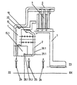
以上、極めて一般的に述べてきた事実を説明するため、問題となっている特性を、ここで再度、図4に示されている現在の技術による多板クラッチ装置に基づく例を使って示す。 In order to explain the facts that have been described very generally, the characteristic in question is again shown here using an example based on the multi-plate clutch device according to the current technology shown in FIG.
図示されている多板クラッチ装置は、基本的にOX軸に関し回転対称に設計され、駆動軸(図示せず)と駆動端部22で連接されているハウジングを備えており、このハウジングは、基本的に中空円筒形の外側プレートディスクキャリア5と、前記基本的に中空円筒形の外側プレートディスクキャリア5と同軸でその内に配置されている基本的に中空円筒形の中心部15.4とで構成されている。多板クラッチ装置のもう1つの構成部品は、出力端部23上で出力軸(図示せず)と連接され、OX軸に関し基本的に回転対称に設計されている、内側プレートディスクキャリア7である。
The illustrated multi-plate clutch device is basically designed to be rotationally symmetric with respect to the OX axis, and includes a housing connected to a driving shaft (not shown) and a
図面から推察できるように、外側及び内側プレートディスクキャリア5及び7は、いわゆる外側及び内側プレートディスク6及び8のキャリアである。これらプレートディスクは、それぞれ外側及び内側プレートディスクキャリア5及び7に基本的にはきつく、但し限定された軸方向運動ができるように取り付けられている。全体の接続装置(fitting arrangement)は、提示例では3枚の外側プレートディスク6、7と3枚の内側プレートディスク8、10で構成され、ディスクパック4と呼ばれる。外側及び内側プレートディスクは交互に配置され、対をなして摩擦接合を形成することができる。ディスクパック4の一方の端部にあり、その軸方向の運動が一方の端部でロッキングリング27により制限されているディスクプレート(ここでは外側プレートディスク)は、エンドプレートと呼ばれる。図4では、このエンドプレートに参照番号9が付されている。ディスクパック4の他方の端部にあるディスクプレート(ここでは内側プレートディスク)は、圧力プレートと呼ばれる。図4では、この圧力プレートに参照番号10が付されている。
As can be inferred from the drawing, the outer and inner
外側及び内側プレートディスクキャリア5、7上の何枚かのプレートディスク(この場合は6枚)で構成されるディスクパック4のこの接続装置は、「実際のクラッチ」と呼ばれる多板クラッチ装置の一部を形成しており、例えば、冷却油室13を経由して供給される冷却油26のような冷却剤によって冷却されるのが望ましい。
This connecting device of the
図4に示す現在の技術による多板クラッチ装置のもう1つの構成部品は、先にも述べた、このクラッチを作動させるための作動装置である。先に詳細に述べた様に、作動装置は、圧力ピストン1とバランスピストン2を備えている。
Another component of the multi-plate clutch device according to the current technology shown in FIG. 4 is an operating device for operating the clutch as described above. As described in detail above, the actuator comprises a
圧力ピストン1は基本的に円形に設計されている。ピストンの内壁は、中心部15.4の外壁上を滑るように案内されており、この中心部は基本的に円筒状のジャケットのような形をしている。圧力ピストン1は、適切な滑動により、ディスクパック4の圧力プレート10に対し、ここでは環状に設計されている適切な圧力要素14を介して押し付けられるので、ディスクパック4が一緒に、軸方向の逃げを持たないエンドプレート9に押し付けられ、個々の隣接するディスクプレート6、8が摩擦連接を形成し、クラッチを作動させる。
The
ハウジングと圧力ピストン1は、互いに嵌合して中空の空間を形成する。この中空の空間が、ここでは2個のシールリング20、21で周囲に対しシールされたいわゆる圧力室であり、図では参照番号11が付されている。
The housing and the
この圧力室11には、中心部15.4内を半径方向に伸びる1つ又は複数の穴を通して、圧力油24を供給できるようになっている。従ってこの穴は圧力油チャネルと呼ばれている。圧力油チャネルの1本を図4に示し、参照番号17を付している。
The
図4に示す代表的実施形態では、先に作動装置の構成部品として命名したバランスピストン2が、基本的に円形に設計されている。バランスピストン2は、圧力ピストン1及びハウジングの中心部15.4と協働して中空の空間を取り囲むように配置されている。この中空の空間はバランス室と呼ばれ、図4では参照番号12が付されている。
In the exemplary embodiment shown in FIG. 4, the
先に述べた圧力室11と同様に、バランス室12は(反対方向)加圧媒体で加圧できるようになっており、この加圧媒体は、今後補償油25と呼ぶことにするが、先に述べた反対方向の圧力を発生させるため適切な穴を通して加えられる。補償油25を加えるための穴を、今後補償油チャネルと呼ぶことにする。図4には、ハウジングの中心部15.4を半径方向に貫通する補償油チャネルの内の1本を示す。これに参照番号18.4を付す。
Similar to the
現在の技術による、提示した代表的な実施形態において、スプリングアッセンブリ3は、バランスピストン2の内壁で支持され、クラッチを作動させる際に圧力ピストン1が滑動する方向とは逆に、圧力ピストン1に対抗して保持されているが、このスプリングアッセンブリ3は、バランス室12内に、更に反対方向の圧力を発生させるように配置されている。
In the exemplary embodiment presented according to the current technology, the
クラッチを作動させる際に、ピストン1の軸方向の滑動でともかくもバランス室12内に適切な反作用圧力が発生するようにするためには、バランス室12をその周囲に対してシールすること、及びバランスピストン2を少なくとも軸方向には動かなくすることの両方が必要である。このうち最初の機能は、圧力ピストン1とバランスピストン2の互いに隣接する壁と壁の間をシールする円周シールリップ19で達成される。軸方向の滑動を止めるのは、現在のの技術によれば、通常、ロックリング16.4で達成される。
In order to ensure that an appropriate reaction pressure is generated in the balance chamber 12 by any axial sliding of the
この接続装置は、原理的には証明済みであるが、なお、費用が掛からずスペースをとらない代替の解決策を提供する必要性が存在している。 While this connection device has been proven in principle, there is still a need to provide an alternative solution that is inexpensive and space-saving.
従って、本発明の目的は、既知のクラッチ装置を、製造の費用が下がり、より小型であるのが特徴となるように、磨きを掛け開発することである。 Accordingly, it is an object of the present invention to polish and develop known clutch devices so that they are characterized by lower manufacturing costs and smaller size.
この課題は、本発明による、請求項1の特徴記載部分に述べる特性を備えた包括的なクラッチ装置によって解決される。本発明のクラッチ装置は、クラッチを動かすための圧力を発生させるための圧力ピストンを有し、前記圧力ピストンはハウジング内で滑動するように案内されており、前記ハウジングと前記圧力ピストンとは圧力室を取り囲み、前記圧力室は、圧力を発生させるために加圧媒体によって加圧できるようになっており、前記圧力ピストン上に反作用圧力を発生させるためのバランスピストンを有し、前記バランスピストンは、前記クラッチが前記圧力ピストンの滑動方向に動かされるとき、前記ハウジングに対して基本的に動かないように保持されており、前記ハウジングと前記圧力ピストンと前記バランスピストンとは、反作用圧力を発生させるために反作用加圧媒体によって加圧することのできるバランス室を取り囲んでおり、掛け止め機構は、前記クラッチが前記圧力ピストンの滑動方向に動かされるとき、基本的に、前記バランスピストンを前記ハウジングに対して動かないように保持することに特徴を有する。
This object is solved by a comprehensive clutch device according to the invention with the characteristics described in the characterizing part of
本発明の有用な実施形態及びその他の開発内容は、従属請求項に述べられている。
本発明の基本的な概念は、クラッチを作動させる際、基本的にバランスピストンをハウジングに対して動かないように保持するために、掛け止め機構または捕捉機構を設けることで構成されている。この型式の掛け止め又は捕捉機構を使うと、バランスピストンを迅速且つ容易に組み立てることができる。更に、掛け止め又は捕捉機構は他の多くの用途で既知なので、確実に、低コストで製造し、省スペースで設計することができる。
Useful embodiments of the invention and other developments are set out in the dependent claims.
The basic concept of the present invention is constituted by providing a latching mechanism or a catching mechanism in order to hold the balance piston so as not to move with respect to the housing when the clutch is operated. With this type of latch or catch mechanism, the balance piston can be assembled quickly and easily. In addition, the latch or capture mechanism is known in many other applications, so it can be reliably manufactured at low cost and designed in a space-saving manner.
本発明の有用な改良型は、ハウジングに割り当てられた少なくとも1つの第1型の掛け止め要素と、バランスピストンに割り当てられた少なくとも1つの第2型の掛け止め要素を備え、前記第1型及び第2型の掛け止め要素が互いに掛け止め又は捕捉係合するようになっている掛け止め又は捕捉機構で構成されており、以後、簡単のため、掛け止め又は捕捉機構を掛け止め機構と呼ぶことにする。この改良型は、ラッチ又はキャッチロックの最も簡単な形態を呈しているので、複雑なツイストキャッチ又はスクリューキャッチ機構よりも好適であるが、勿論これらも考えられる。 A useful refinement of the invention comprises at least one first-type latching element assigned to the housing and at least one second-type latching element assigned to the balance piston, said first type and The second type of latching element is comprised of a latching or catching mechanism that is adapted to latch or catch each other, and for the sake of simplicity, hereinafter the latching or catching mechanism will be referred to as the latching mechanism. To. This improved version is preferred over complex twist catch or screw catch mechanisms as it presents the simplest form of latch or catch lock, but of course these are also conceivable.
この改良型のある特定の実施形態では、本発明は、バランスピストンの構成部品となる第2型の掛け止め要素を提供している。しかし場合によっては、第2型の掛け止め要素が別体のバランスピストン保持装置の構成部品であると好都合なこともあり、恐らくこれが特に設けられている場合にはそうである。必要ならば、両方の改良型を組み合わせて利用することもできる。 In one particular embodiment of this improvement, the present invention provides a second type latching element that is a component of the balance piston. In some cases, however, it may be advantageous for the second type latching element to be a component of a separate balance piston holding device, perhaps if this is provided. If necessary, a combination of both types can be used.
いずれの場合も、提示された課題への解決策が提供される。
ハウジングが、基本的に軸に関し回転対称に設計され、基本的に円筒形ジャケットのような形をした中心部を備えており、中心部の外側壁は、基本的に円形に設計されている圧力ピストンの内側壁を、圧力ピストンが軸方向に滑動するように案内し、中心部の上には、クラッチを圧力ピストンの軸方向の滑動方向に作動させる際には、同様に円形に設計されているバランスピストンが動かないように保持される場合で、特に、図4に示されているように現在の技術による多板クラッチ装置を含んでいる場合には、本発明によれば、中心部の内側壁又は外側壁を基本的に同軸に回転する溝である第1型の掛け止め要素と、前記回転する溝と係合してロックすることのできる少なくとも1つの掛け止めクリップ又はデテントを備えている第2型の掛け止め要素とが提供される。
In either case, a solution to the presented problem is provided.
The housing is designed to be basically rotationally symmetric about an axis and has a central part essentially shaped like a cylindrical jacket, the outer wall of the central part being designed to be essentially circular The inner wall of the piston is guided in such a way that the pressure piston slides in the axial direction, and above the center, the clutch is likewise designed to be circular when operating in the axial sliding direction of the pressure piston. According to the present invention, in the case where the balance piston is held stationary, in particular when it includes a multi-plate clutch device according to the state of the art as shown in FIG. A first-type latching element that is a groove that rotates coaxially on the inner wall or the outer wall, and at least one latching clip or detent that can be engaged and locked with the rotating groove. The second type Only a stop element is provided.
前記少なくとも1つの掛け止めクリップ又はデテントは、バランスピストン又はバランスピストン保持装置から基本的に軸方向に離れているフィンガの端部に形成されるのが望ましい。フィンガの端部に取り付けられている多数のこれら掛け止めクリップは、通常、バランスピストン又はバランスピストン保持装置の円形の端部に同軸に取り付けられている。この他、本発明によれば、同軸に回転するよう設計された単一の掛け止めクリップも提供されている。 The at least one latching clip or detent is preferably formed at the end of the finger that is essentially axially away from the balance piston or balance piston retainer. A number of these latching clips attached to the ends of the fingers are usually attached coaxially to the circular end of the balance piston or balance piston retainer. In addition, according to the present invention, a single latching clip designed to rotate coaxially is also provided.
本発明の別の実施形態では、更に、図4のバランスピストンと同様なバランスピストンと嵌合するよう設計されている、円形であるのが望ましいバランスピストン保持装置が提供されている。 In another embodiment of the present invention, there is further provided a balance piston holding device, preferably circular, designed to mate with a balance piston similar to the balance piston of FIG.
本発明の3つの代表的な実施形態を図面に示して、現在の技術による多板クラッチ装置の1つの実例と比較することとする。 Three representative embodiments of the present invention are shown in the drawings and will be compared with one example of a multi-plate clutch device according to the state of the art.
本発明の代表的な実施形態を、以下に更に詳しく説明する。
本発明の全ての代表的な実施形態は、上に詳細に説明し、図4に示している既知の多板クラッチ装置から進化させたものである。従って、以下に記載する多板クラッチ装置の全ての代表的実施形態に関し、全ての個々の構成要素は全く同じに説明される。同じ構成要素を割り当て易くするために、全ての図面で、同じ構成要素には同じ参照番号を付している。
Exemplary embodiments of the invention are described in further detail below.
All exemplary embodiments of the present invention are an evolution of the known multi-plate clutch device described in detail above and shown in FIG. Thus, for all exemplary embodiments of the multi-plate clutch device described below, all individual components are described identically. To facilitate the assignment of the same components, the same components are denoted by the same reference numerals in all drawings.
以下に言及する全ての多板クラッチ装置は、基本的に軸OXに関し回転対称になるよう設計され、駆動軸(図示せず)に駆動端部22で接合されているハウジングを備えており、ハウジングは、基本的に中空の円筒形の外側プレートディスクキャリア5と、前記基本的に中空の円筒形の外側プレートディスクキャリア5と同軸で、その中に配置されている基本的に中空の円筒形中心部とで構成され、前記中心部には、本発明による改良に基づく本発明の異なる代表的実施形態の各図面で、15.1から15.3の異なる参照番号が割り当てられている。
All the multi-plate clutch devices mentioned below are basically designed to be rotationally symmetric with respect to the axis OX, and include a housing joined to a drive shaft (not shown) at a
更に、図4に示す現在の技術による多板クラッチ装置に対応する、図1から図3に示す多板クラッチ装置は、先に述べた軸OXに関し基本的に回転対称に設計され、駆動軸(図示せず)に駆動端部23で接続されている内側プレートディスクキャリア7を備えている。
Further, the multi-plate clutch device shown in FIGS. 1 to 3 corresponding to the multi-plate clutch device according to the current technology shown in FIG. An inner
更に、ディスクパック4を形成する3つの外側ディスクプレート及び3つの内側ディスクプレート6及び8が備えられており、ディスクプレート6、8は、それぞれ外側及び内側ディスクプレートキャリア5及び7に、基本的にはきつく、但し限定された軸方向運動ができるように取り付けられている。
In addition, three outer disk plates and three
ディスクパック4の一方の端部に位置し、軸方向の運動がその端部で係止リング27によって拘束されている外側ディスクプレート、いわゆるエンドプレートに、図1、2、3では、図4と同じく参照番号9が付されている。ディスクパック4の他方の端部に位置している内側ディスクプレート、いわゆる圧力プレートに、図1、2、3では、図4と同じく参照番号10が付されている。
The outer disk plate, so-called end plate, which is located at one end of the
多板クラッチ装置の構成部品は、この他に、圧力ピストン1とバランスピストン2がある。本発明による全ての代表的実施形態(図1から3)では、圧力ピストン1に、クラッチを動かすための環状に設計された圧力要素14が設けられている。
Other components of the multi-plate clutch device include a
圧力ピストン1の内側壁は、基本的に円筒形ジャケットのような形をした中心部15.1(図1a)、15.2(図2)、15.3(図3a)の外側壁上を滑動するように案内されている。ハウジングと圧力ピストン1は、協働していわゆる圧力室11を形成するように配置されている。この圧力室11は、その周囲に対し2つのシールリング20、21によってシールされている。図1から3を見ると分かるように、中心部15.1、15.2、15.3内には圧力油チャネルが設けられている。
The inner wall of the
図1から3の全ての実施形態において、バランスピストン2は基本的に円形に設計されており、各圧力ピストン1及びハウジングの各中心部15.1、15.2、15.3と協働して、いわゆるバランス室12を取り囲むように配置されている。
In all the embodiments of FIGS. 1 to 3, the
バランス室12をその周囲に対してシールするため、シールリップ19が、圧力ピストン1とバランスピストン2の互いに隣接する環状壁の間に設けられている。
In order to seal the balance chamber 12 against its surroundings, a sealing
現在の技術に相当する代表的な実施形態と同じく、本発明による全ての各実施形態においても、スプリングアッセンブリ3は、バランスピストン2の内壁で支持され、クラッチを作動させる際に圧力ピストン1が滑動する方向とは逆に、圧力ピストン1に対抗して保持されており、各バランス室12内に配置されている。
As in the typical embodiments corresponding to the current technology, in all the embodiments according to the present invention, the
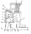
図1a及び図1bは、本発明による掛け止め機構を備えた、自動車用クラッチ装置の第1の代表的実施形態を示している。本例では、掛け止め機構は、基本的にリング状のバランスピストン2の内側周辺上に、独立した(ここでは6個の)フィンガ30.1を、等間隔に、基本的に先端を軸方向に向けて配置し、各フィンガの自由端上に、掛け止めクリップ即ちデテント31.1を半径方向外側に向いた返りとして形成することによって実現されている。これに対応して、中心部15.1には、円筒ジャケット形状の壁の内側に同軸に周回する溝28.1を巡らし、半径方向内側に向いた、同軸に周回する掛け止めクリップ即ちデテント29.1を形成して、この溝に、フィンガ30.1の先端に形成されたバランスピストン2の掛け止めクリップ31.1が係合してバランスピストン2をハウジングにロックすることができるようになっている。なお、個々のフィンガ30.1の間の空隙は、補償油25用の補償油チャネル18.1の役も果たしている。
1a and 1b show a first exemplary embodiment of an automotive clutch device with a latch mechanism according to the invention. In this example, the latching mechanism basically has independent (in this case, six) fingers 30.1 on the inner periphery of the ring-shaped
図2は、本発明による掛け止め機構を備えた自動車用クラッチ装置の第2の代表的実施形態を示している。本実施形態では、掛け止め機構は、基本的にリング状のバランスピストン2の内側周辺上に、独立したフィンガ30.2を、基本的に先端を軸方向に向けて配置し、各フィンガの自由端上に、掛け止めクリップ即ちデテント31.2を半径方向内側に向いた返りとして形成することによって実現されている。これに対応して、中心部15.2には、円筒ジャケット形状の壁の外側に同軸に周回する溝28.2を巡らし、半径方向外側に向いた、同軸に周回する掛け止めクリップ即ちデテント29.2を形成している。この場合も、個々のフィンガ30.2の間の空隙は、補償油25用の補償油チャネル18.2の役も果たしている。
FIG. 2 shows a second exemplary embodiment of an automotive clutch device provided with a latching mechanism according to the present invention. In the present embodiment, the latching mechanism basically has an independent finger 30.2 arranged on the inner periphery of the ring-shaped
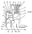
図3a及び図3bは、本発明による掛け止め機構を備えた自動車用クラッチ装置の第3の代表的実施形態を示している。ここで示されている例では、掛け止め機構は、バランスピストン2に、基本的にリング状の専用の円筒形リテイニングリング32.3を設けることによって実現されている。このリテイニングリング32.3の一方の端部は、バランスピストン2の内側周辺を囲んでいる。先に述べたバランスピストン2と同じ様に、このリテイニングリング32.3の他方の側はフィンガ30.3となり、フィンガは基本的に軸方向に伸び、フィンガの端部は、ここでは図1a及び図1bに示した第1の代表的実施形態と同じ掛け止めクリップ即ちデテント31.3を形成している。先の例とは異なり、外向きの掛け止めクリップ即ちデテント31.3は、周回形状(円周方向に連続する形状)に設計されているので、フィンガ30.3の端部は閉じたリングを形成している。当業者には自明であるように、この型式のリテイニングリング32.3の掛け止め機構は、先に述べたバランスピストン2の掛け止め機構と同様に設計することもできるし、その逆でもよい。
3a and 3b show a third exemplary embodiment of an automotive clutch device with a latching mechanism according to the invention. In the example shown here, the latching mechanism is realized by providing the
完全を期すために述べるが、これに対応して、中心部15.3には、円筒ジャケット形状の壁の内側に同軸に周回する溝28.3を巡らし、半径方向内側に向いた、同軸に周回する掛け止めクリップ即ちデテント29.3を形成して、この溝28.3に、フィンガ30.3の先端に形成されている、リテイニングリング32.2の掛け止めクリップ即ちデテント31.3が係合してバランスピストン2をハウジングにロックすることができるようになっている。
Correspondingly, for the sake of completeness, correspondingly, the central part 15.3 has a groove 28.3 that circulates coaxially inside the cylindrical jacket-shaped wall and is coaxially oriented radially inward. A looping latch clip or detent 29.3 is formed, and in this groove 28.3 there is a latch clip or detent 31.3 of the retaining ring 32.2 formed at the tip of the finger 30.3. By engaging, the
本発明の上記詳細な説明は、解説を目的としたものである。当業者には自明であるように、本発明の範囲から逸脱することなく様々な変更及び修正を施すことができる。従って、上記説明は全て、解説のためのもので限定する意図はなく、本発明の範囲は、特許請求の範囲に述べる事項によってのみ定義されるものと理解されたい。 The above detailed description of the present invention is for illustrative purposes. It will be apparent to those skilled in the art that various changes and modifications can be made without departing from the scope of the invention. Accordingly, it is to be understood that the above description is illustrative only and is not intended to be limiting, and that the scope of the present invention is defined only by the matters recited in the claims.
1 圧力ピストン 2 バランスピストン
3 スプリングアッセンブリ 4 ディスクパック
5 外側プレートディスクキャリア 6 外側プレートディスク
7 内側プレートディスクキャリア 8 内側プレートディスク
9 エンドプレート 10 圧力プレート
11 圧力室 12 バランス室
15 中心部 27 係止リング
28 溝 29、31 掛け止めクリップ
30 フィンガー 32 リテイニングリング
DESCRIPTION OF
Claims (11)
クラッチ(4、9、8、10、27)を動かすための圧力を発生させるための圧力ピストン(1)を有し、前記圧力ピストン(1)はハウジング(5、15.1、15.2)内で滑動するように案内されており、前記ハウジング(5、15.1、15.2)と前記圧力ピストン(1)とは圧力室(11)を取り囲み、前記圧力室は、圧力を発生させるために加圧媒体(24)によって加圧できるようになっており、前記圧力ピストン(1)上に反作用圧力を発生させるためのバランスピストン(2)を有し、前記バランスピストン(2)は、リング状であり、前記バランスピストン(2)は、前記クラッチ(4、9、8、10、27)が前記圧力ピストン(1)の滑動方向に動かされるとき、前記ハウジング(5、15.1、15.2)に対して動かないように保持されており、前記ハウジング(5、15.1、15.2)と前記圧力ピストン(1)と前記バランスピストン(2)とは、反作用圧力を発生させるために反作用加圧媒体によって加圧することのできるバランス室(12)を取り囲んでおり、
掛け止め機構(28.1、28.2、29.1、29.2、30.1、30.2、31.1、31.2)は、前記クラッチ(4、9、8、10、27)が前記圧力ピストン(1)の滑動方向に動かされるとき、前記バランスピストン(2)を前記ハウジング(5、15.1、15.2)に対して動かないように保持し、
前記掛け止め機構(28.1、28.2、29.1、29.2、30.1、30.2、31.1、31.2)は、前記ハウジング(5、15.1、15.2)の一部である少なくとも1つの第1型の掛け止め要素(28.1、28.2、29.1、29.2)と、前記バランスピストン(2)の一部である少なくとも1つの第2型の掛け止め要素とを備えており、前記第2型の掛け止め要素は、軸方向に延在する複数のフィンガ(30.1、30.2)の端部に、半径方向に延在する複数のデテント(31.1、31.2)を有し、前記第1型及び第2型の掛け止め要素(28.1、28.2、29.1、29.2、30.1、30.2、31.1、31.2)が、互いに掛け止め係合するようになっており、
前記バランスピストン(2)は、前記複数のフィンガ(30.1、30.2)の間に配置された複数の油チャネル(18.1,18.2)を有することを特徴とするクラッチ装置。 In the clutch device,
A pressure piston (1) for generating pressure for moving the clutch (4, 9 , 8 , 10 , 27), said pressure piston (1) being a housing (5 , 15.1 , 15.2 ); The housing (5 , 15.1 , 15.2 ) and the pressure piston (1) surround a pressure chamber (11), which generates pressure. The pressure piston (1) has a balance piston (2) for generating a reaction pressure on the pressure piston (1), and the balance piston (2) It is ring-shaped and the balance piston (2) is arranged such that when the clutch (4 , 9 , 8 , 10 , 27) is moved in the sliding direction of the pressure piston (1), the housing (5 , 15.1,. 15.2) It is held stationary against the housing (5,15.1, 15.2) and the and the pressure piston (1) and the balance piston (2), reaction pressure in order to generate a reaction pressure balance chamber that can be pressurized by the pressure medium (12) surrounds,
Multiplying only stop mechanism (28.1, 28.2, 29.1, 29.2, 30.1, 30.2, 31.1, 31.2), the clutch (4,9,8,10, 27) holds the balance piston (2) against movement with respect to the housing (5 , 15.1 , 15.2 ) when moved in the sliding direction of the pressure piston (1);
The latch mechanism (28.1 , 28.2 , 29.1 , 29.2 , 30.1 , 30.2 , 31.1 , 31.2 ) is connected to the housing (5 , 15.1 , 15.1 ) . 2 ) at least one first-type latching element (28.1, 28.2, 29.1, 29.2 ) that is part of the balance piston (2) and a element latched in the second type, the latching element of the second type are the ends of the plurality of fingers (30.1, 30.2) extending in the axial direction, the radial direction A plurality of extending detents (31.1, 31.2) and the first and second type latching elements (28.1, 28.2, 29.1, 29.2, 30. 1, 30.2, 31.1 , 31.2 ) are engaged with each other ,
The clutch device according to claim 1, wherein the balance piston (2) has a plurality of oil channels (18.1, 18.2) disposed between the plurality of fingers (30.1, 30.2) .
クラッチ(4、9、8、10、27)を動かすための圧力を発生させるための圧力ピストン(1)を有し、前記圧力ピストン(1)はハウジング(5、15.3)内で滑動するように案内されており、前記ハウジング(5、15.3)と前記圧力ピストン(1)とは圧力室(11)を取り囲み、前記圧力室は、圧力を発生させるために加圧媒体(24)によって加圧できるようになっており、前記圧力ピストン(1)上に反作用圧力を発生させるためのバランスピストン(2)を有し、前記バランスピストン(2)は、リング状であり、前記バランスピストン(2)は、前記クラッチ(4、9、8、10、27)が前記圧力ピストン(1)の滑動方向に動かされるとき、前記ハウジング(5、15.3)に対して動かないように保持されており、前記ハウジング(5、15.3)と前記圧力ピストン(1)と前記バランスピストン(2)とは、反作用圧力を発生させるために反作用加圧媒体によって加圧することのできるバランス室(12)を取り囲んでおり、
円筒形のバランスピストン保持装置(32.3)は、前記バランスピストンの内側周辺を囲む一方の端部を有し、かつ、軸方向に延在するフィンガと、前記フィンガ(30.3)の端部において、半径方向に延在しているデテント(31.3)とを有し、
掛け止め機構(28.3、29.3、30.3、31.3)は、前記クラッチ(4、9、8、10、27)が前記圧力ピストン(1)の滑動方向に動かされるとき、前記バランスピストン(2)を前記ハウジング(5、15.3)に対して動かないように保持し、
前記掛け止め機構(28.3、29.3、30.3、31.3)は、前記ハウジング(5、15.3)の一部である少なくとも1つの第1型の掛け止め要素(28.3、29.3)と、前記バランスピストン保持装置(32.3)の一部である少なくとも1つの第2型の掛け止め要素(30.3、31.3)とを備えており、前記第1型及び第2型の掛け止め要素(28.3、29.3、30.3、31.3)が、互いに掛け止め係合するようになっていることを特徴とするクラッチ装置。 In the clutch device,
Having a pressure piston (1) for generating pressure for moving the clutch (4, 9, 8, 10, 27), said pressure piston (1) sliding in the housing (5, 15.3 ) The housing (5, 15.3 ) and the pressure piston (1) surround a pressure chamber (11), which is pressurized medium (24) for generating pressure. And a balance piston (2) for generating a reaction pressure on the pressure piston (1), the balance piston (2) is ring-shaped, and the balance piston (2) is held so as not to move relative to the housing (5, 15.3 ) when the clutch (4, 9, 8, 10, 27) is moved in the sliding direction of the pressure piston (1) Is Cage, the housing (5, 15.3) and the pressure piston (1) and said A balance piston (2), the balance chamber that can be pressurized by the reaction pressure medium in order to generate a reaction pressure (12) Surrounding
Cylindrical balance piston holding device (32.3) has one end portion surrounding the inner periphery of said balance piston, and a finger extending axially, before Symbol fingers (30.3) a Oite detent extending radially and (31.3) at the end portion,
The latching mechanism ( 28.3, 29.3, 30.3, 31.3 ) is used when the clutch (4, 9, 8, 10, 27 ) is moved in the sliding direction of the pressure piston (1). Holding the balance piston (2) against movement with respect to the housing (5, 15.3 );
The latching mechanism (28.3, 29.3, 30.3, 31.3) is at least one first-type latching element ( 28. 3) that is part of the housing (5, 15.3 ) . 3, 29.3 ) and at least one second-type latching element (30.3, 31.3) that is part of the balance piston holding device (32.3) , A clutch device, wherein the first type and second type latching elements ( 28.3, 29.3, 30.3, 31.3 ) are adapted to latch and engage with each other.
クラッチ(4、9、8、10、27)を動かすための圧力を発生させるための圧力ピストン(1)を有し、前記圧力ピストン(1)はハウジング(5、15.1、15.2、15.3)内で滑動するように案内されており、前記ハウジング(5、15.1、15.2、15.3)と前記圧力ピストン(1)とは圧力室(11)を取り囲み、前記圧力室は、圧力を発生させるために加圧媒体(24)によって加圧できるようになっており、前記圧力ピストン(1)上に反作用圧力を発生させるためのバランスピストン(2)を有し、前記バランスピストン(2)は、リング状であり、前記バランスピストン(2)は、前記クラッチ(4、9、8、10、27)が前記圧力ピストン(1)の滑動方向に動かされるとき、前記ハウジング(5、15.1、15.2、15.3)に対して動かないように保持されており、前記ハウジング(5、15.1、15.2、15.3)と前記圧力ピストン(1)と前記バランスピストン(2)とは、反作用圧力を発生させるために反作用加圧媒体によって加圧することのできるバランス室(12)を取り囲んでおり、
掛け止め機構(28.1、28.2、28.3、29.1、29.2、29.3、30.1、30.2、30.3、31.1、31.2、31.3)は、前記クラッチ(4、9、8、10、27)が前記圧力ピストン(1)の滑動方向に動かされるとき、前記バランスピストン(2)を前記ハウジング(5、15.1、15.2、15.3)に対して動かないように保持し、
前記掛け止め機構(28.1、28.2、28.3、29.1、29.2、29.3、30.1、30.2、30.3、31.1、31.2、31.3)は、前記ハウジング(5、15.1、15.2、15.3)の一部である少なくとも1つの第1型の掛け止め要素(28.1、28.2、28.3、29.1、29.2、29.3)と、前記バランスピストン(2)又はバランスピストン保持装置(32.3)の一部である少なくとも1つの第2型の掛け止め要素とを備えており、前記第2型の掛け止め要素は、軸方向に延在する複数のフィンガ(30.1、30.2、30.3)の端部に、半径方向に延在する複数のデテント(31.1、31.2、31.3)を有し、前記第1型及び第2型の掛け止め要素(28.1、28.2、28.3、29.1、29.2、29.3、30.1、30.2、30.3、31.1、31.2、31.3)が、互いに掛け止め係合するようになっており、
複数の油チャネル(18.1,18.2、18.3)が前記複数のフィンガ(30.1、30.2)の間に配置されていることを特徴とするクラッチ装置。 In the clutch device,
A pressure piston (1) for generating pressure for moving the clutch (4, 9 , 8 , 10 , 27), said pressure piston (1) being a housing (5 , 15.1 , 15.2, 15.3 ) are slidably guided in the housing (5 , 15.1, 15.2 , 15.3 ) and the pressure piston (1) surround the pressure chamber (11), The pressure chamber can be pressurized by a pressurizing medium (24) to generate pressure, and has a balance piston (2) for generating a reaction pressure on the pressure piston (1), The balance piston (2) is ring-shaped, and the balance piston (2) is configured such that when the clutch (4, 9, 8, 10, 27) is moved in the sliding direction of the pressure piston (1), Housing (5, 1 5.1 , 15.2, 15.3 ) are held against movement , the housing (5 , 15.1, 15.2 , 15.3 ), the pressure piston (1) and the The balance piston (2) surrounds a balance chamber (12) that can be pressurized with a reaction pressurizing medium to generate a reaction pressure ,
Multiplied only stop mechanism (28.1, 28.2,28.3, 29.1, 29.2,29.3, 30.1, 30.2,30.3, 31.1, 31.2,31 .3 ) when the clutch (4, 9, 8, 10, 27) is moved in the sliding direction of the pressure piston (1), the balance piston (2) is moved into the housing (5 , 15.1 , 15). .2, 15.3 ) hold against movement ,
The latch mechanism (28.1, 28.2, 28.3, 29.1, 29.2, 29.3, 30.1, 30.2, 30.3, 31.1, 31.2, 31) .3) at least one first-type latching element (28.1, 28.2, 28.3, which is part of said housing (5 , 15.1, 15.2 , 15.3 ) , and 29.1,29.2,29.3), said balance piston (2) or and at least one second-type latching element which is a part of the balance piston holding device (32.3) The second type latching element has a plurality of detents (31) extending in the radial direction at ends of a plurality of fingers (30.1, 30.2, 30.3) extending in the axial direction. has .1,31.2,31.3), the first-type and second-type latching element (28.1, 28.2 28.3,29.1,29.2,29.3,30.1,30.2,30.3,31.1,31.2,31.3) is, to stop engaging over each other We have been,
A clutch device, wherein a plurality of oil channels (18.1, 18.2, 18.3) are arranged between the plurality of fingers (30.1, 30.2) .
Applications Claiming Priority (2)
| Application Number | Priority Date | Filing Date | Title |
|---|---|---|---|
| EP02010541.7 | 2002-05-10 | ||
| EP02010541A EP1361374B1 (en) | 2002-05-10 | 2002-05-10 | Clutch device for motor vehicle or the like |
Related Parent Applications (1)
| Application Number | Title | Priority Date | Filing Date |
|---|---|---|---|
| JP2003128588A Division JP4373124B2 (en) | 2002-05-10 | 2003-05-07 | Clutch device |
Publications (2)
| Publication Number | Publication Date |
|---|---|
| JP2009264593A JP2009264593A (en) | 2009-11-12 |
| JP5084792B2 true JP5084792B2 (en) | 2012-11-28 |
Family
ID=29225638
Family Applications (2)
| Application Number | Title | Priority Date | Filing Date |
|---|---|---|---|
| JP2003128588A Expired - Fee Related JP4373124B2 (en) | 2002-05-10 | 2003-05-07 | Clutch device |
| JP2009160387A Expired - Fee Related JP5084792B2 (en) | 2002-05-10 | 2009-07-07 | Clutch device |
Family Applications Before (1)
| Application Number | Title | Priority Date | Filing Date |
|---|---|---|---|
| JP2003128588A Expired - Fee Related JP4373124B2 (en) | 2002-05-10 | 2003-05-07 | Clutch device |
Country Status (5)
| Country | Link |
|---|---|
| US (1) | US6935481B2 (en) |
| EP (1) | EP1361374B1 (en) |
| JP (2) | JP4373124B2 (en) |
| KR (1) | KR20030087529A (en) |
| DE (1) | DE50213287D1 (en) |
Families Citing this family (9)
| Publication number | Priority date | Publication date | Assignee | Title |
|---|---|---|---|---|
| GB0508275D0 (en) * | 2005-04-25 | 2005-06-01 | Visual Edge Ltd | Fastening system |
| DE102006057915A1 (en) | 2006-10-11 | 2008-05-15 | Borg Warner Inc., Auburn Hills | Clutch and clutch assembly with such a clutch |
| US9464808B2 (en) * | 2008-11-05 | 2016-10-11 | Parker-Hannifin Corporation | Nozzle tip assembly with secondary retention device |
| US8453819B2 (en) | 2010-02-22 | 2013-06-04 | Twin Disc, Inc. | Balanced clutch system |
| DE102018201781A1 (en) | 2018-02-06 | 2019-08-08 | Zf Friedrichshafen Ag | coupling device |
| DE102018201782A1 (en) | 2018-02-06 | 2019-08-08 | Zf Friedrichshafen Ag | clutch assembly |
| KR102089482B1 (en) * | 2018-06-27 | 2020-04-23 | 평화오일씰공업 주식회사 | Automatic transmission clutch unit |
| US11512747B2 (en) * | 2020-01-09 | 2022-11-29 | Cnh Industrial America Llc | Balanced piston clutch |
| DE102020128743B4 (en) | 2020-07-22 | 2024-02-22 | Schaeffler Technologies AG & Co. KG | Coupling device |
Family Cites Families (12)
| Publication number | Priority date | Publication date | Assignee | Title |
|---|---|---|---|---|
| JPS54163257U (en) * | 1978-05-08 | 1979-11-15 | ||
| JPS5682313U (en) * | 1979-11-30 | 1981-07-03 | ||
| US4813808A (en) * | 1983-08-19 | 1989-03-21 | Gkn Automotive Components Inc. | Axial retaining member and method for interconnecting male and female splined members |
| JP2832440B2 (en) * | 1988-11-04 | 1998-12-09 | アイシン・エィ・ダブリュ株式会社 | Automatic transmission clutch mounting structure |
| US4898493A (en) * | 1989-03-16 | 1990-02-06 | Karl Blankenburg | Method and apparatus for assembling parts |
| US5048656A (en) * | 1990-08-29 | 1991-09-17 | Eaton Corporation | Fluid operated clutch control system having latch member |
| DE4035686C1 (en) * | 1990-11-09 | 1992-01-23 | Ford-Werke Ag, 5000 Koeln, De | |
| JPH04191530A (en) * | 1990-11-21 | 1992-07-09 | Nissan Motor Co Ltd | Wet multiple disc clutch device |
| US5172799A (en) * | 1991-02-08 | 1992-12-22 | Toyota Jidosha Kabushiki Kaisha | Centrifugal hydraulic cancel mechanism for the rotating clutch |
| JP2768133B2 (en) * | 1992-05-18 | 1998-06-25 | 三菱自動車工業株式会社 | Fluid pressure clutch device |
| US6202814B1 (en) * | 1999-08-24 | 2001-03-20 | Borgwarner Inc. | Automatic transmission having grounded clutch with convergent cooling |
| JP6003229B2 (en) * | 2012-05-24 | 2016-10-05 | コベルコ建機株式会社 | Boom drive device for construction machinery |
-
2002
- 2002-05-10 EP EP02010541A patent/EP1361374B1/en not_active Expired - Lifetime
- 2002-05-10 DE DE50213287T patent/DE50213287D1/en not_active Expired - Lifetime
-
2003
- 2003-04-09 KR KR10-2003-0022155A patent/KR20030087529A/en not_active Ceased
- 2003-05-02 US US10/428,545 patent/US6935481B2/en not_active Expired - Fee Related
- 2003-05-07 JP JP2003128588A patent/JP4373124B2/en not_active Expired - Fee Related
-
2009
- 2009-07-07 JP JP2009160387A patent/JP5084792B2/en not_active Expired - Fee Related
Also Published As
| Publication number | Publication date |
|---|---|
| DE50213287D1 (en) | 2009-04-02 |
| EP1361374A1 (en) | 2003-11-12 |
| US6935481B2 (en) | 2005-08-30 |
| EP1361374B1 (en) | 2009-02-18 |
| KR20030087529A (en) | 2003-11-14 |
| JP4373124B2 (en) | 2009-11-25 |
| JP2004003648A (en) | 2004-01-08 |
| US20050072647A1 (en) | 2005-04-07 |
| JP2009264593A (en) | 2009-11-12 |
Similar Documents
| Publication | Publication Date | Title |
|---|---|---|
| JP5084792B2 (en) | Clutch device | |
| KR102320710B1 (en) | Hydraulic control system for a wet double clutch | |
| KR102320711B1 (en) | Wet double clutch supported on its control system | |
| JP2005527758A (en) | Speed change transmission for automobiles with multiple clutches operable by hydraulic pressure | |
| JP5282316B2 (en) | SEAL HOLDER DEVICE AND POWER TRANSMISSION DEVICE HAVING SEAL HOLDER DEVICE | |
| JP7293866B2 (en) | friction fastening device | |
| KR102382445B1 (en) | Wet double clutch with centered force transmission mechanisms | |
| JP2006010080A (en) | Start clutch and fixed disc assembly having torque detector | |
| JP7255357B2 (en) | friction fastening device | |
| US20080121483A1 (en) | Hydrodynamic torque converter | |
| JP2011002054A (en) | Centrifugal oil pressure cancel structure for automatic transmission | |
| JP7051272B2 (en) | Friction fastening device | |
| JP2790063B2 (en) | mechanical seal | |
| JP6779083B2 (en) | Torque converter | |
| JP6976775B2 (en) | Torque converter | |
| CN116438386A (en) | Friction device and transmission device with return spring element | |
| US10634228B2 (en) | Torque converter | |
| US11365769B2 (en) | Energy efficient A/C compressor clutch | |
| KR950006273A (en) | Clutch release assembly | |
| JP7232649B2 (en) | pulley device | |
| JP2000039035A (en) | Spring holding structure for annular rotating member | |
| JP2005083558A (en) | Hydraulic clutch blocking device | |
| JP2007155071A (en) | Piston for automatic transmission for vehicle | |
| JP6060929B2 (en) | Automatic transmission | |
| CN114096757A (en) | Actuating device for multi-disc brake and transmission comprising actuating device and multi-disc brake |
Legal Events
| Date | Code | Title | Description |
|---|---|---|---|
| A521 | Written amendment |
Free format text: JAPANESE INTERMEDIATE CODE: A523 Effective date: 20100427 |
|
| A131 | Notification of reasons for refusal |
Free format text: JAPANESE INTERMEDIATE CODE: A131 Effective date: 20111209 |
|
| A977 | Report on retrieval |
Free format text: JAPANESE INTERMEDIATE CODE: A971007 Effective date: 20111215 |
|
| A601 | Written request for extension of time |
Free format text: JAPANESE INTERMEDIATE CODE: A601 Effective date: 20120308 |
|
| A602 | Written permission of extension of time |
Free format text: JAPANESE INTERMEDIATE CODE: A602 Effective date: 20120313 |
|
| A521 | Written amendment |
Free format text: JAPANESE INTERMEDIATE CODE: A523 Effective date: 20120405 |
|
| TRDD | Decision of grant or rejection written | ||
| A01 | Written decision to grant a patent or to grant a registration (utility model) |
Free format text: JAPANESE INTERMEDIATE CODE: A01 Effective date: 20120806 |
|
| A01 | Written decision to grant a patent or to grant a registration (utility model) |
Free format text: JAPANESE INTERMEDIATE CODE: A01 |
|
| A61 | First payment of annual fees (during grant procedure) |
Free format text: JAPANESE INTERMEDIATE CODE: A61 Effective date: 20120904 |
|
| R150 | Certificate of patent or registration of utility model |
Ref document number: 5084792 Country of ref document: JP Free format text: JAPANESE INTERMEDIATE CODE: R150 Free format text: JAPANESE INTERMEDIATE CODE: R150 |
|
| FPAY | Renewal fee payment (event date is renewal date of database) |
Free format text: PAYMENT UNTIL: 20150914 Year of fee payment: 3 |
|
| R250 | Receipt of annual fees |
Free format text: JAPANESE INTERMEDIATE CODE: R250 |
|
| R250 | Receipt of annual fees |
Free format text: JAPANESE INTERMEDIATE CODE: R250 |
|
| R250 | Receipt of annual fees |
Free format text: JAPANESE INTERMEDIATE CODE: R250 |
|
| R250 | Receipt of annual fees |
Free format text: JAPANESE INTERMEDIATE CODE: R250 |
|
| R250 | Receipt of annual fees |
Free format text: JAPANESE INTERMEDIATE CODE: R250 |
|
| LAPS | Cancellation because of no payment of annual fees |