JP5074032B2 - Fuel cell system and control method thereof - Google Patents
Fuel cell system and control method thereof Download PDFInfo
- Publication number
- JP5074032B2 JP5074032B2 JP2006532669A JP2006532669A JP5074032B2 JP 5074032 B2 JP5074032 B2 JP 5074032B2 JP 2006532669 A JP2006532669 A JP 2006532669A JP 2006532669 A JP2006532669 A JP 2006532669A JP 5074032 B2 JP5074032 B2 JP 5074032B2
- Authority
- JP
- Japan
- Prior art keywords
- fuel
- amount
- fuel cell
- aqueous
- solution
- Prior art date
- Legal status (The legal status is an assumption and is not a legal conclusion. Google has not performed a legal analysis and makes no representation as to the accuracy of the status listed.)
- Expired - Fee Related
Links
Images


Classifications
-
- H—ELECTRICITY
- H01—ELECTRIC ELEMENTS
- H01M—PROCESSES OR MEANS, e.g. BATTERIES, FOR THE DIRECT CONVERSION OF CHEMICAL ENERGY INTO ELECTRICAL ENERGY
- H01M8/00—Fuel cells; Manufacture thereof
- H01M8/04—Auxiliary arrangements, e.g. for control of pressure or for circulation of fluids
- H01M8/04298—Processes for controlling fuel cells or fuel cell systems
- H01M8/043—Processes for controlling fuel cells or fuel cell systems applied during specific periods
- H01M8/04302—Processes for controlling fuel cells or fuel cell systems applied during specific periods applied during start-up
-
- H—ELECTRICITY
- H01—ELECTRIC ELEMENTS
- H01M—PROCESSES OR MEANS, e.g. BATTERIES, FOR THE DIRECT CONVERSION OF CHEMICAL ENERGY INTO ELECTRICAL ENERGY
- H01M8/00—Fuel cells; Manufacture thereof
- H01M8/04—Auxiliary arrangements, e.g. for control of pressure or for circulation of fluids
- H01M8/04082—Arrangements for control of reactant parameters, e.g. pressure or concentration
- H01M8/04186—Arrangements for control of reactant parameters, e.g. pressure or concentration of liquid-charged or electrolyte-charged reactants
-
- H—ELECTRICITY
- H01—ELECTRIC ELEMENTS
- H01M—PROCESSES OR MEANS, e.g. BATTERIES, FOR THE DIRECT CONVERSION OF CHEMICAL ENERGY INTO ELECTRICAL ENERGY
- H01M8/00—Fuel cells; Manufacture thereof
- H01M8/04—Auxiliary arrangements, e.g. for control of pressure or for circulation of fluids
- H01M8/04223—Auxiliary arrangements, e.g. for control of pressure or for circulation of fluids during start-up or shut-down; Depolarisation or activation, e.g. purging; Means for short-circuiting defective fuel cells
- H01M8/04225—Auxiliary arrangements, e.g. for control of pressure or for circulation of fluids during start-up or shut-down; Depolarisation or activation, e.g. purging; Means for short-circuiting defective fuel cells during start-up
-
- H—ELECTRICITY
- H01—ELECTRIC ELEMENTS
- H01M—PROCESSES OR MEANS, e.g. BATTERIES, FOR THE DIRECT CONVERSION OF CHEMICAL ENERGY INTO ELECTRICAL ENERGY
- H01M8/00—Fuel cells; Manufacture thereof
- H01M8/10—Fuel cells with solid electrolytes
- H01M8/1009—Fuel cells with solid electrolytes with one of the reactants being liquid, solid or liquid-charged
- H01M8/1011—Direct alcohol fuel cells [DAFC], e.g. direct methanol fuel cells [DMFC]
-
- Y—GENERAL TAGGING OF NEW TECHNOLOGICAL DEVELOPMENTS; GENERAL TAGGING OF CROSS-SECTIONAL TECHNOLOGIES SPANNING OVER SEVERAL SECTIONS OF THE IPC; TECHNICAL SUBJECTS COVERED BY FORMER USPC CROSS-REFERENCE ART COLLECTIONS [XRACs] AND DIGESTS
- Y02—TECHNOLOGIES OR APPLICATIONS FOR MITIGATION OR ADAPTATION AGAINST CLIMATE CHANGE
- Y02E—REDUCTION OF GREENHOUSE GAS [GHG] EMISSIONS, RELATED TO ENERGY GENERATION, TRANSMISSION OR DISTRIBUTION
- Y02E60/00—Enabling technologies; Technologies with a potential or indirect contribution to GHG emissions mitigation
- Y02E60/30—Hydrogen technology
- Y02E60/50—Fuel cells
Description
この発明は燃料電池システムおよびその制御方法に関し、より特定的には、燃料電池のアノードに燃料水溶液を循環供給する燃料電池システムおよびその制御方法に関する。 The present invention relates to a fuel cell system and a control method thereof, and more particularly to a fuel cell system that circulates and supplies a fuel aqueous solution to an anode of a fuel cell and a control method thereof.
近年、直接メタノール型燃料電池システムにおいて、起動開始から発電量を最大にするまでの時間を短くすることが望まれており、その方策として燃料電池に供給されるメタノール水溶液の所定温度までの昇温時間を短くすることが提案されている。 In recent years, in direct methanol fuel cell systems, it has been desired to shorten the time from the start of startup until the amount of power generation is maximized. As a measure for this, the temperature of the aqueous methanol solution supplied to the fuel cell is increased to a predetermined temperature. It has been proposed to shorten the time.
たとえば特許文献1では、燃料貯蔵部とセルスタックとの間に昇温手段を設け、起動時に燃料貯蔵部からメタノール水溶液の一部を昇温手段に供給してメタノール水溶液の温度を上昇させる技術が開示されている。この昇温手段は白金触媒を含み、メタノール水溶液を白金触媒と空気に接触させることによって酸化させ反応熱を発生させる。
特許文献1の技術を用いれば、燃料電池に供給されるメタノール水溶液の昇温を早めることはできるが、メタノール水溶液の一部は酸化されてしまうのでメタノールの利用効率が悪くなる。
If the technique of
それゆえに、この発明の主たる目的は、燃料の利用効率を悪化することなく燃料電池に供給される燃料水溶液の所定温度までの昇温時間を短くすることができる燃料電池システムおよびその制御方法を提供することである。 SUMMARY OF THE INVENTION Therefore, a main object of the present invention is to provide a fuel cell system and a control method therefor that can shorten the temperature rise time of the aqueous fuel solution supplied to the fuel cell to a predetermined temperature without deteriorating the fuel utilization efficiency. It is to be.
この発明のある見地によれば、アノードを有する燃料電池、燃料電池のアノードに燃料水溶液を循環供給する燃料供給手段、燃料供給手段によって循環される燃料水溶液の量を調整する水溶液量調整手段、および燃料電池から排出される液体を収容する水タンクを備え、水溶液量調整手段は、燃料供給手段内の燃料水溶液を水タンクに移送可能に構成され、起動時の燃料供給手段内の燃料水溶液の量を通常運転時より少なく設定する、燃料電池システムが提供される。 According to an aspect with the present invention, a fuel cell, the fuel supply means to circulate and supply the aqueous fuel solution to the anode of the fuel cell, fuel aqueous solution amount adjusting means for adjusting the amount of the aqueous fuel solution to be circulated by the supply means having an anode, And a water tank for storing the liquid discharged from the fuel cell , the aqueous solution amount adjusting means is configured to be able to transfer the aqueous fuel solution in the fuel supply means to the water tank, and the aqueous fuel solution in the fuel supply means at startup A fuel cell system is provided in which the amount is set lower than during normal operation.
この発明では、燃料電池システムの起動時における燃料供給手段内の燃料水溶液の量を通常運転時のそれより少なくする、すなわち、燃料電池システムの起動時における燃料水溶液の循環量を通常運転時のそれより少なくする。これによって、燃料電池に循環供給される燃料水溶液の熱容量を小さくできるので、燃料水溶液の所定温度までの昇温時間を短くでき、起動後に短時間で発電量を最大近傍にまでできる。また、燃料水溶液の酸化によって加熱するものではないので、燃料の利用効率も悪化しない。さらに、燃料供給手段内の余分な燃料水溶液を水タンクに移送すればよいので、他のタンクを別途準備する必要がない。 In the present invention, the amount of the aqueous fuel solution in the fuel supply means at the time of starting the fuel cell system is made smaller than that at the time of normal operation, that is, the circulation amount of the aqueous fuel solution at the time of starting the fuel cell system is that of the normal operation. Less. As a result, the heat capacity of the aqueous fuel solution circulated and supplied to the fuel cell can be reduced, so that the time for raising the temperature of the aqueous fuel solution to a predetermined temperature can be shortened, and the amount of power generation can be brought close to the maximum in a short time after startup. Moreover, since it does not heat by oxidation of fuel aqueous solution, the utilization efficiency of fuel does not deteriorate. Furthermore, since it is only necessary to transfer the excess fuel aqueous solution in the fuel supply means to the water tank, it is not necessary to prepare another tank separately.
この発明の他の見地によれば、アノードを有する燃料電池、燃料電池のアノードに燃料水溶液を循環供給する燃料供給手段、燃料供給手段によって循環される燃料水溶液の量を調整する水溶液量調整手段、および燃料供給手段内の燃料水溶液を退避させるための退避用タンクを備え、水溶液量調整手段は、燃料供給手段内の燃料水溶液を退避用タンクに退避可能に構成され、起動時の燃料供給手段内の燃料水溶液の量を通常運転時より少なく設定する、燃料電池システムが提供される。According to another aspect of the present invention, a fuel cell having an anode, a fuel supply means for circulatingly supplying a fuel aqueous solution to the anode of the fuel cell, an aqueous solution amount adjusting means for adjusting the amount of the aqueous fuel solution circulated by the fuel supply means, And a retreat tank for retreating the aqueous fuel solution in the fuel supply means, and the aqueous solution amount adjusting means is configured to retreat the aqueous fuel solution in the fuel supply means to the retreat tank, and in the fuel supply means at the time of startup. A fuel cell system is provided in which the amount of the aqueous fuel solution is set to be smaller than that during normal operation.
この発明では、燃料電池システムの起動時における燃料供給手段内の燃料水溶液の量を通常運転時のそれより少なくする、すなわち、燃料電池システムの起動時における燃料水溶液の循環量を通常運転時のそれより少なくする。これによって、燃料電池に循環供給される燃料水溶液の熱容量を小さくできるので、燃料水溶液の所定温度までの昇温時間を短くでき、起動後に短時間で発電量を最大近傍にまでできる。また、燃料水溶液の酸化によって加熱するものではないので、燃料の利用効率も悪化しない。さらに、燃料供給手段内の余分な燃料水溶液を退避用タンクに退避させることによって、既存の燃料電池システムに手を加える必要はなく、また燃料電池システムを構成する他の構成部材に影響を及ぼすこともない。In the present invention, the amount of the aqueous fuel solution in the fuel supply means at the time of starting the fuel cell system is made smaller than that at the time of normal operation. Less. As a result, the heat capacity of the aqueous fuel solution circulated and supplied to the fuel cell can be reduced, so that the time for raising the temperature of the aqueous fuel solution to a predetermined temperature can be shortened and the amount of power generation can be brought to the maximum in a short time after startup. Moreover, since it does not heat by oxidation of fuel aqueous solution, the utilization efficiency of fuel does not deteriorate. Furthermore, by retracting the excess aqueous fuel solution in the fuel supply means to the retreat tank, there is no need to modify the existing fuel cell system, and other components constituting the fuel cell system are affected. Nor.
好ましくは、燃料電池の温度を検出する温度検出手段をさらに備え、水溶液量調整手段は温度検出手段によって検出された燃料電池の温度に基づいて燃料供給手段内の燃料水溶液の量を調整する。この場合、燃料電池の温度安定性を確保しつつ燃料水溶液を早く昇温できる。また、燃料水溶液量を過度に少なくすることはなく、ポンプを用いて液量を制御する場合には当該ポンプの駆動時間を最適にし消費電力を少なくできる。Preferably, temperature detection means for detecting the temperature of the fuel cell is further provided, and the aqueous solution amount adjustment means adjusts the amount of the aqueous fuel solution in the fuel supply means based on the temperature of the fuel cell detected by the temperature detection means. In this case, the temperature of the fuel aqueous solution can be increased quickly while ensuring the temperature stability of the fuel cell. Further, the amount of the aqueous fuel solution is not excessively reduced, and when the amount of liquid is controlled using a pump, the driving time of the pump can be optimized to reduce power consumption.
この発明のその他の見地によれば、アノードを有する燃料電池、燃料電池のアノードに燃料水溶液を循環供給する燃料供給手段、燃料供給手段によって循環される燃料水溶液の量を調整する水溶液量調整手段、燃料電池に電気的に接続される二次電池、および二次電池の蓄電量を検出するための蓄電量検出手段を備え、水溶液量調整手段は、蓄電量検出手段によって検出された蓄電量に応じて燃料供給手段内の燃料水溶液の量を調整し、起動時の燃料供給手段内の燃料水溶液の量を通常運転時より少なく設定する、燃料電池システムが提供される。According to another aspect of the present invention, a fuel cell having an anode, a fuel supply unit that circulates and supplies a fuel aqueous solution to the anode of the fuel cell, an aqueous solution amount adjustment unit that adjusts the amount of the aqueous fuel solution circulated by the fuel supply unit, A secondary battery electrically connected to the fuel cell, and a storage amount detection means for detecting the storage amount of the secondary battery, the aqueous solution amount adjustment means depending on the storage amount detected by the storage amount detection means Thus, a fuel cell system is provided in which the amount of the aqueous fuel solution in the fuel supply means is adjusted, and the amount of the aqueous fuel solution in the fuel supply means at startup is set to be smaller than that during normal operation.
この発明のさらにその他の見地によれば、アノードを有する燃料電池と、燃料電池のアノードに燃料水溶液を循環供給する燃料供給手段と、燃料電池に電気的に接続される二次電池とを備える燃料電池システムの制御方法であって、起動時の燃料供給手段内の燃料水溶液の量を通常運転時より少なく設定するように、二次電池の蓄電量に基づいて燃料供給手段内の燃料水溶液の量を調整する、燃料電池システムの制御方法が提供される。According to still another aspect of the present invention, a fuel comprising a fuel cell having an anode, fuel supply means for circulatingly supplying a fuel aqueous solution to the anode of the fuel cell, and a secondary battery electrically connected to the fuel cell. A control method for a battery system, wherein the amount of aqueous fuel solution in the fuel supply means at the time of start-up is set to be less than that during normal operation, based on the charged amount of the secondary battery. A method for controlling the fuel cell system is provided.
この発明では、燃料電池システムの起動時における燃料供給手段内の燃料水溶液の量を通常運転時のそれより少なくする、すなわち、燃料電池システムの起動時における燃料水溶液の循環量を通常運転時のそれより少なくする。これによって、燃料電池に循環供給される燃料水溶液の熱容量を小さくできるので、燃料水溶液の所定温度までの昇温時間を短くでき、起動後に短時間で発電量を最大近傍にまでできる。また、燃料水溶液の酸化によって加熱するものではないので、燃料の利用効率も悪化しない。さらに、二次電池の蓄電量に応じて初期の燃料供給手段内の燃料水溶液の量を調整することによって、二次電池の蓄電量がなくなる前に燃料水溶液を所定の発電温度にまで昇温できる。In the present invention, the amount of the aqueous fuel solution in the fuel supply means at the time of starting the fuel cell system is made smaller than that at the time of normal operation. Less. As a result, the heat capacity of the aqueous fuel solution circulated and supplied to the fuel cell can be reduced, so that the time for raising the temperature of the aqueous fuel solution to a predetermined temperature can be shortened and the amount of power generation can be brought to the maximum in a short time after startup. Moreover, since it does not heat by oxidation of fuel aqueous solution, the utilization efficiency of fuel does not deteriorate. Furthermore, by adjusting the amount of the aqueous fuel solution in the initial fuel supply means according to the amount of electricity stored in the secondary battery, the aqueous fuel solution can be raised to a predetermined power generation temperature before the amount of electricity stored in the secondary battery runs out. .
また、好ましくは、燃料供給手段は燃料水溶液を収容する水溶液タンクを含み、水溶液量調整手段は水溶液タンク内の燃料水溶液の量を調整する。この場合、水溶液タンク内の燃料水溶液の量を調整すればよいので、燃料供給手段内の燃料水溶液の量の調整が容易になる。 Preferably, the fuel supply means includes an aqueous solution tank that stores the aqueous fuel solution, and the aqueous solution amount adjusting means adjusts the amount of the aqueous fuel solution in the aqueous solution tank. In this case, it is only necessary to adjust the amount of the aqueous fuel solution in the aqueous solution tank, so that the adjustment of the amount of the aqueous fuel solution in the fuel supply means is facilitated.
さらに、好ましくは、水溶液量調整手段は燃料供給手段内の燃料水溶液の量を起動後の通常運転時には所定量となるように増加させる。この場合、起動時には燃料水溶液の量を少なくすることによって昇温を早くできるとともに、所定温度に達した後の通常運転時には燃料水溶液の量が所定量まで増加しているので熱容量を確保でき、系の温度および燃料水溶液の濃度等が安定する。 Further preferably, the aqueous solution amount adjusting means increases the amount of the aqueous fuel solution in the fuel supply means so that it becomes a predetermined amount during normal operation after startup. In this case, the temperature can be increased quickly by reducing the amount of the aqueous fuel solution at the start-up, and the heat capacity can be secured because the amount of the aqueous fuel solution has increased to the predetermined amount during normal operation after reaching the predetermined temperature. The temperature and the concentration of the aqueous fuel solution are stabilized.
好ましくは、燃料電池の温度を検出する温度検出手段をさらに備え、水溶液量調整手段は温度検出手段によって検出された燃料電池の温度に応じて燃料供給手段内の燃料水溶液の量を増加させる。この場合、燃料電池の温度に応じて燃料供給手段内の燃料水溶液の量を徐々に増加させていくので、燃料電池の温度安定性を損なうことなく燃料水溶液を所定量まで戻すことができる。 Preferably, temperature detection means for detecting the temperature of the fuel cell is further provided, and the aqueous solution amount adjustment means increases the amount of the aqueous fuel solution in the fuel supply means according to the temperature of the fuel cell detected by the temperature detection means. In this case, since the amount of the aqueous fuel solution in the fuel supply means is gradually increased according to the temperature of the fuel cell, the aqueous fuel solution can be returned to a predetermined amount without deteriorating the temperature stability of the fuel cell.
また、好ましくは、燃料電池の温度を検出する温度検出手段をさらに備え、水溶液量調整手段は、温度検出手段によって検出された燃料電池の温度が所定温度に達したとき、燃料電池の温度が当該所定温度を維持するように燃料供給手段内の燃料水溶液の量を増加させる。この場合、燃料電池の温度が所定温度を維持するように、燃料供給手段内の燃料水溶液の量を増加させていくので、燃料電池の温度安定性を損なうことなく燃料水溶液を所定量まで戻すことができる。 Preferably, the apparatus further comprises temperature detecting means for detecting the temperature of the fuel cell, and the aqueous solution amount adjusting means is configured such that when the temperature of the fuel cell detected by the temperature detecting means reaches a predetermined temperature, the temperature of the fuel cell The amount of the aqueous fuel solution in the fuel supply means is increased so as to maintain a predetermined temperature. In this case, the amount of the aqueous fuel solution in the fuel supply means is increased so that the temperature of the fuel cell is maintained at the predetermined temperature. Therefore, the aqueous fuel solution can be returned to the predetermined amount without impairing the temperature stability of the fuel cell. Can do.
さらに、好ましくは、燃料電池の温度を検出する温度検出手段をさらに備え、水溶液量調整手段は、温度検出手段によって検出された燃料電池の温度が所定温度に達したとき、燃料供給手段内の燃料水溶液の量を所定量まで増加させる。このように、燃料電池の温度が所定温度に達したとき、燃料供給手段内の燃料水溶液の量を通常運転時の所定量まで一気に増加させることによって、迅速に通常運転に移行することができる。 Further, preferably, the apparatus further comprises temperature detecting means for detecting the temperature of the fuel cell, and the aqueous solution amount adjusting means is configured to detect the fuel in the fuel supply means when the temperature of the fuel cell detected by the temperature detecting means reaches a predetermined temperature. The amount of aqueous solution is increased to a predetermined amount. As described above, when the temperature of the fuel cell reaches a predetermined temperature, it is possible to quickly shift to the normal operation by increasing the amount of the aqueous fuel solution in the fuel supply means to the predetermined amount during the normal operation.
輸送機器の場合には据え置き型の場合よりも燃料電池システムを小さくすることが要求され、たとえば二次電池の容量にも制限があり、起動時に燃料水溶液を早く昇温させ短時間で通常運転に移行することが要求される。したがって、この発明は輸送機器に好適に用いられる。 In the case of transportation equipment, it is required to make the fuel cell system smaller than in the case of the stationary type, for example, the capacity of the secondary battery is also limited. It is required to migrate. Therefore, this invention is suitably used for transportation equipment.
この発明において、燃料電池のアノードに燃料水溶液を「循環供給」するとは、燃料電池のアノードから排出された燃料水溶液をも含んで燃料水溶液を燃料電池のアノードに供給することをいう。 In this invention, “circulating supply” of the aqueous fuel solution to the anode of the fuel cell means that the aqueous fuel solution including the aqueous fuel solution discharged from the anode of the fuel cell is supplied to the anode of the fuel cell.
また、燃料電池システムの「起動時」とは、燃料電池システムのメインスイッチをONした後、通常運転に入るまでをいう。燃料電池システムの「通常運転」とは、定常的な発電状態をいい、たとえば燃料電池の温度と通常の水溶液量で設定されている燃料電池の目標温度との差が10℃以内の範囲にある運転状態をいう。 Further, “at the time of start-up” of the fuel cell system refers to a period from when the main switch of the fuel cell system is turned on until normal operation is started. “Normal operation” of the fuel cell system refers to a steady power generation state. For example, the difference between the temperature of the fuel cell and the target temperature of the fuel cell set by the amount of the normal aqueous solution is within 10 ° C. The driving state.
この発明の上述の目的およびその他の目的、特徴、局面および利点は、添付図面に関連して行われる以下の実施例の詳細な説明から一層明らかとなろう。 The above and other objects, features, aspects and advantages of the present invention will become more apparent from the detailed description of the following examples given in conjunction with the accompanying drawings.
10 燃料電池システム
12 燃料電池
12b アノード
15,22,54 水位センサ
18 水溶液タンク
40,42,108 パイプ
41 燃料供給手段
44 水タンク
58 水還流パイプ
60 水ポンプ
66 温度センサ
70 制御回路
72 CPU
76 メモリ
102 二次電池
103 蓄電量検出装置
106 退避用タンク
110 ポンプ
200 車体フレーム
202 モータ
S メタノール水溶液DESCRIPTION OF
76
以下、図面を参照してこの発明の実施の形態について説明する。
図1〜図4に示すように、この発明の一実施形態の燃料電池システム10は、直接メタノール型燃料電池システムとして構成される。直接メタノール型燃料電池システムは改質器が不要であるので、携帯性を要する機器や小型化が望まれる機器に好適に用いられる。ここでは、燃料電池システム10を輸送機器の一例である自動二輪車に用いる場合について説明する。なお、図2に示すように、自動二輪車については車体フレーム200のみを示し、図2において左側が車両前方、右側が車両後方である。燃料電池システム10は車体フレーム200に沿って配置される。Embodiments of the present invention will be described below with reference to the drawings.
As shown in FIGS. 1-4, the
図1を主に参照して、燃料電池システム10は燃料電池12を含む。燃料電池12は、電解質12aと電解質12aを両側から挟むアノード(燃料極)12bおよびカソード(空気極)12cとを含む複数の直接メタノール型燃料電池セルを直列に接続(積層)した燃料電池セルスタックとして構成される。
Referring mainly to FIG. 1, the
また、燃料電池システム10は、高濃度のメタノール燃料(メタノールを約50wt%程度含む水溶液)Fを収容する燃料タンク14を含み、燃料タンク14は燃料供給パイプ16を介して燃料水溶液としてのメタノール水溶液Sが収容される水溶液タンク18に接続される。燃料供給パイプ16には燃料ポンプ20が介挿され、燃料ポンプ20の駆動によって燃料タンク14内のメタノール燃料Fが水溶液タンク18に供給される。
The
燃料タンク14には水位センサ15が装着され、燃料タンク14内のメタノール燃料Fの水位が検出される。また、水溶液タンク18には水位センサ22が装着され、水溶液タンク18内のメタノール水溶液Sの水位が検出される。水位センサ15,22は、たとえばフロートセンサからなり、タンク内の水位の変化に伴ってフロート部(図示せず)が浮動することによってタンク内の水位を検出できる。言い換えれば、浮動するフロート部の位置に基づいてタンク内の液量(水量)を検出できる。後述する水位センサ54についても同様である。
A
水溶液タンク18は、水溶液パイプ24を介して燃料電池12のアノード12bに接続される。水溶液パイプ24には、上流側から水溶液ポンプ26、熱交換器として機能するラジエータ28、および水溶液フィルタ30が順に介挿される。ラジエータ28の近傍にはラジエータ28を冷却するための冷却ファン32が配置される。水溶液タンク18内のメタノール水溶液Sは、水溶液ポンプ26によってアノード12bに向けて供給され、必要に応じてラジエータ28によって冷却され、さらに水溶液フィルタ30によって浄化されてアノード12bに供給される。
The
一方、燃料電池12のカソード12cにはエアポンプ34がエア側パイプ36を介して接続され、エア側パイプ36にはエアフィルタ38が介挿される。したがって、エアポンプ34からの酸素を含む空気がエアフィルタ38によって浄化されたのちカソード12cに与えられる。
On the other hand, an
また、アノード12bと水溶液タンク18とはパイプ40を介して接続され、アノード12bから排出される未反応のメタノール水溶液や生成された二酸化炭素が水溶液タンク18に与えられる。
The
この実施形態では、水溶液タンク18、水溶液パイプ24、水溶液ポンプ26、ラジエータ28、水溶液フィルタ30、冷却ファン32およびパイプ40を含んで、燃料供給手段41が構成され、燃料供給手段41によってメタノール水溶液Sが燃料電池12のアノード12bに循環供給される。
In this embodiment, the fuel supply means 41 is configured including the
さらに、カソード12cにはパイプ42を介して水タンク44が接続される。パイプ42には気液分離器として機能するラジエータ46が介挿され、ラジエータ46近傍にはラジエータ46を冷却するための冷却ファン48が配置される。カソード12cから排出される水分(水および水蒸気)を含む排気がパイプ42を介して水タンク44に与えられる。エアポンプ34の駆動によって水タンク44への当該排気の導入が促進される。
Further, a
また、水溶液タンク18と水タンク44とはCO2ベントパイプ50を介して接続される。CO2ベントパイプ50にはメタノール水溶液Sを分離するためのメタノールトラップ52が介挿される。これによって、水溶液タンク18から排出される二酸化炭素が水タンク44に与えられる。The
水タンク44には、水位センサ54が装着され、水タンク44内の水位が検出される。また、水タンク44には排気ガスパイプ56が取り付けられ、排気ガスパイプ56から二酸化炭素とカソード12cからの排気とが排出される。水タンク44内には、液体として、反応で生成された水とクロスオーバーされた微量のメタノールとが収容される。
A
水タンク44は水還流パイプ58を介して水溶液タンク18に接続され、水還流パイプ58には水ポンプ60が介挿される。この実施形態では、水ポンプ60は、水溶液や水の圧送方向をA方向またはB方向に切り替えることができる。水溶液タンク18の状況に応じて水ポンプ60による圧送方向を切り替えることによって、水溶液が水タンク44から水溶液タンク18へ(矢印A方向)あるいはその逆方向に(矢印B方向)送られる。この実施形態では、水還流パイプ58の一方端部は、水溶液タンク18内において水溶液中に浸かるように延ばされている。換言すると、この燃料電池システム10では、メタノール水溶液Sを循環供給する経路から一時的に別の収容空間(タンク)に収容して、循環する水溶液量を容易に減少させることができる。
The
また、水溶液パイプ24において、ラジエータ28と水溶液フィルタ30との間には、バイパスパイプ62が形成される。
In the
図4をも参照して、さらに燃料電池システム10においては、バイパスパイプ62にメタノール水溶液Sの濃度を検出するための濃度センサ64が設けられ、燃料電池12の温度を検出するための温度センサ66が燃料電池12に装着され、外気温度を検出するための外気温度センサ68がエアポンプ34近傍に設けられる。この実施形態では、温度センサ66によって検出された燃料電池12の温度を、循環するメタノール水溶液Sの温度とみなす。燃料電池12の温度として、セルスタック自体の温度を検出してもよいし、カソード12cからの排気の温度を検出してもよい。
Referring also to FIG. 4, in the
図4に示すように、燃料電池システム10は制御回路70を含む。
制御回路70は、必要な演算を行い燃料電池システム10の動作を制御するための制御手段としてのCPU72、CPU72にクロックを与えるクロック回路74、燃料電池システム10の動作を制御するためのプログラムやデータおよび演算データ等を格納するための、たとえばEEPROMからなるメモリ76、燃料電池システム10の誤動作を防ぐためのリセットIC78、外部機器と接続するためのインターフェイス回路80、自動二輪車を駆動するモータ202に燃料電池12を接続するための電気回路82における電圧を検出するための電圧検出回路84、電気回路82を流れる電流を検出するための電流検出回路86、電気回路82を開閉するためのON/OFF回路88、電気回路82の過電圧を防止するための電圧保護回路90、電気回路82に設けられるダイオード92、および電気回路82に所定の電圧を供給するための電源回路94を含む。As shown in FIG. 4, the
The
このような制御回路70のCPU72には、濃度センサ64、温度センサ66および外気温度センサ68からの検出信号が入力され、また転倒の有無を検知する転倒スイッチ96からの検知信号や各種設定や情報入力のための入力部98からの信号が与えられる。さらに、CPU72には、水位センサ15,22および54からの検出信号も与えられる。
Detection signals from the
また、CPU72によって、燃料ポンプ20、水溶液ポンプ26、エアポンプ34、熱交換器用冷却ファン32、気液分離器用冷却ファン48および水ポンプ60等の補機類が制御される。また、CPU72によって、各種情報を表示し、自動二輪車の搭乗者に各種情報を報知するための表示部100が制御される。
Further, the
また、燃料電池12には二次電池102と二次電池102の蓄電量(残存容量)を検出するための蓄電量検出装置103とが接続される。二次電池102および蓄電量検出装置103の直列接続はモータ202に並列接続される。二次電池102は、燃料電池12からの出力を補完するものであり、燃料電池12からの電気エネルギーによって充電され、その放電によってモータ202や補機類に電気エネルギーを与える。
Further, the
モータ202には、モータ202の各種データを計測するためのメータ204が接続され、メータ204によって計測されたデータやモータ202の状況は、インターフェイス回路104を介してCPU72に与えられる。
A
なお、メモリ76には、図5(a)に示すような燃料電池12の温度と目標水溶液量との対応関係を示すテーブルデータが格納され、さらに、図6〜図8に示すような動作を実行するためのプログラム等が格納される。なお、図5(b)は、燃料電池12の温度と目標水溶液量との対応関係を示すグラフである。ここで、目標水溶液量とは、水溶液タンク18内に収容されるメタノール水溶液Sの目標量をいう。
The
図5からわかるように、燃料電池温度が高いほど、目標水溶液量が多く設定されるので、この場合に水溶液タンク18内が満タンであれば、起動時に水溶液タンク18から減少(退避)させる液量を少なくでき、別のタンクに移送するための電力量を小さくできる。一方、燃料電池温度が低いほど目標水溶液量は小さく設定され、この場合、多くの水溶液が別のタンクに移送され、起動初期における昇温速度を上げることができる。
As can be seen from FIG. 5, the higher the fuel cell temperature, the larger the target aqueous solution amount is set. In this case, if the inside of the
なお、通常運転時においては、水溶液タンク18内のメタノール水溶液Sの量が多ければ多いほど、燃料電池12および燃料供給手段41を循環するメタノール水溶液Sの温度を安定させ、水溶液中のメタノールの濃度むらを少なくできる。したがって、メタノール水溶液量は多いほど燃料電池システム10の運転上、好ましいといえる。
During normal operation, the greater the amount of aqueous methanol solution S in the
この実施形態では、水還流パイプ58、水ポンプ60および制御回路70を含んで、水溶液量調整手段が構成される。
In this embodiment, the aqueous solution amount adjusting means includes the
このような燃料電池システム10の発電時の動作について説明する。
発電開始時には、水溶液タンク18内に収容された所望の濃度のメタノール水溶液Sが水溶液ポンプ26の駆動によって燃料電池12に向けて送られ、必要に応じてラジエータ28で冷却され、水溶液フィルタ30によって浄化されてアノード12bに供給される。一方、酸素を含む空気がエアポンプ34の駆動によって燃料電池12に向けて送られ、エアフィルタ38によって浄化されカソード12cに供給される。The operation of the
At the start of power generation, a methanol aqueous solution S having a desired concentration stored in the
燃料電池12のアノード12bでは、メタノール水溶液Sのメタノールと水とが電気化学反応して二酸化炭素と水素イオンとが生成され、生成された水素イオンは、電解質12aを通ってカソード12cに流入する。この水素イオンは、カソード12cに供給された空気中の酸素と電気化学反応して、水(水蒸気)と電気エネルギーとが生成される。
In the
燃料電池12のアノード12bで生成された二酸化炭素はパイプ40、水溶液タンク18およびCO2ベントパイプ50を通って水タンク44に与えられ、排気ガスパイプ56から排出される。Carbon dioxide produced at the
一方、燃料電池12のカソード12cで生成された水蒸気の大部分は液化して水となって排出されるが、飽和水蒸気分はガス状態で排出される。カソード12cから排出された水蒸気の一部は、ラジエータ46で冷却され露点を下げることによって液化される。ラジエータ46による水蒸気の液化動作は、冷却ファン48を動作させることによって行われる。カソード12cからの水分(水および水蒸気)ならびに未反応の空気はパイプ42を通って水タンク44に与えられる。また、水のクロスオーバーによってカソード12cに移動した水がカソード12cから排出され水タンク44に与えられる。さらに、メタノールのクロスオーバーによってカソード12cで生成された水と二酸化炭素がカソード12cから排出され水タンク44に与えられる。
On the other hand, most of the water vapor generated at the
なお、水のクロスオーバーとは、アノード12bで生成された水素イオンのカソード12cへの移動に伴って、数モルの水がカソード12cへ移動する現象である。メタノールのクロスオーバーとは、水素イオンのカソード12cへの移動に伴って、メタノールがカソード12cへ移動する現象である。カソード12cにおいて、メタノールはエアポンプ34から供給される空気と反応して水と二酸化炭素とに分解される。
The water crossover is a phenomenon in which several moles of water move to the
水タンク44に回収された水(液体)は、水ポンプ60の駆動によって水還流パイプ58を経由して水溶液タンク18に適宜還流され、メタノール水溶液Sの水として利用される。
The water (liquid) collected in the
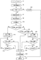
ついで、燃料電池システム10の起動時の主要動作の一例について説明する。
図6を参照して、まず、図示しないメインスイッチがオンされ、メインスイッチオンの信号がCPU72に入力される(ステップS1)。すると、電源電圧が立ち上がるまで待機し安定状態になると、蓄電量検出装置103によって二次電池102の蓄電量(残存容量)が検出される(ステップS3)。検出された二次電池102の蓄電量に基づいて水ポンプ60を駆動できるか否かが判断される(ステップS5)。Next, an example of the main operation at the start-up of the
Referring to FIG. 6, first, a main switch (not shown) is turned on, and a main switch on signal is input to CPU 72 (step S1). Then, when it waits until the power supply voltage rises and becomes stable, the charged amount (remaining capacity) of the
検出された二次電池102の蓄電量が、発電に必要な電力(補機類駆動用電力)を供給するのに十分な量であるならば、水ポンプ60を駆動できると判断され、温度センサ66によって燃料電池12の温度が検出される(ステップS7)。
If the detected amount of power stored in the
図5に示すテーブルデータを参照して、ステップS7で検出された温度に対応する目標水溶液量が選択・決定される(ステップS9)。そして、水位センサ22によって水溶液タンク18内の現在のメタノール水溶液Sの量が検出される(ステップS11)。検出された水溶液量が燃料電池温度すなわち燃料水溶液温度によって決定される目標水溶液量より多いか否かが判断される(ステップS13)。検出された水溶液量の方が多ければ(ステップS13がYES)、二次電池102の電力によって水ポンプ60が駆動され、水溶液タンク18内のメタノール水溶液Sが水還流パイプ58を経由して水タンク44へ(図1に示すB方向へ)送られる(ステップS15)。そして、水溶液タンク18内の水溶液量が目標水溶液量になったか否かが判断される(ステップS17)。水溶液タンク18内の水溶液量がまだ目標水溶液量になっていなければ、ステップS19において一定時間経過するまでメタノール水溶液Sの圧送が継続される。一定時間経過すれば再びステップS17において目標水溶液量になったか否かが判断される。ステップS17において、水溶液タンク18内の水溶液量が目標水溶液量になるまで上述のメタノール水溶液Sの圧送が継続され、ステップS17がYESになれば、水ポンプ60が停止される(ステップS21)。
With reference to the table data shown in FIG. 5, the target aqueous solution amount corresponding to the temperature detected in step S7 is selected and determined (step S9). Then, the current amount of the methanol aqueous solution S in the
一方、ステップS13において水溶液タンク18内の水溶液量が目標水溶液量より多くなければ、水溶液量が目標水溶液量より少ないか否かが判断される(ステップS23)。水溶液量が目標水溶液量より少なければ、二次電池102の電力によって水ポンプ60が駆動され、水タンク44内の水または水溶液が水還流パイプ58を経由して水溶液タンク18へ(図1に示すA方向へ)送られる(ステップS25)。水溶液タンク18内の水溶液量の方が目標水溶液量より少ない場合としては、運転停止後長時間経過していてクロスオーバーによって水溶液が水溶液タンク18から漏れ出した場合が考えられる。
On the other hand, if the amount of the aqueous solution in the
そして、上記の水溶液量調整動作によって水溶液タンク18内の水溶液量が目標水溶液量に到達したか否かが判断される(ステップS27)。水溶液タンク18内の水溶液量がまだ目標水溶液量になっていなければ、ステップS29において一定時間経過するまで水または水溶液の圧送が継続される。一定時間経過すれば再びステップS27において目標水溶液量になったか否かが判断される。ステップS27において、水溶液タンク18内の水溶液量が目標水溶液量になるまで上述の圧送が継続され、ステップS27がYESになれば、水ポンプ60が停止される(ステップS21)。
Then, it is determined whether or not the amount of the aqueous solution in the
また、ステップS23がNOであれば、すなわち水溶液タンク18内の水溶液量が目標水溶液量と等しければ、直接ステップS21に進む。
If step S23 is NO, that is, if the amount of the aqueous solution in the
ステップS21の後に、水溶液タンク18内の水溶液濃度が所望値になるように調整される(ステップS30)。このとき、たとえば、水溶液タンク18内に濃度センサ(図示せず)を設けておき、その濃度センサによって水溶液濃度を検出する。そして、水溶液濃度が所望値より低ければ燃料タンク14からメタノール燃料を補充し、水溶液濃度が所望値より高ければ水タンク44から水または水溶液を補充する。
After step S21, the aqueous solution concentration in the
その後、燃料ポンプ20、水溶液ポンプ26、エアポンプ34、熱交換器用冷却ファン32、気液分離器用冷却ファン48および水ポンプ60等の補機類が駆動され、発電が行われる(ステップS31)。
Thereafter, the auxiliary devices such as the
なお、二次電池102の蓄電量が、発電に必要な電力(補機類駆動用電力)を供給できないほど少なければ、ステップS5において水ポンプ60を駆動できないと判断される。この場合には、燃料電池システム10がダウンしてしまうことを防止するため、水ポンプ60を駆動せずに別の処理を施して(ステップS33)、ステップS31に進み発電を開始する。
Note that if the amount of power stored in the
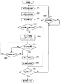
ついで、図7を参照して、燃料電池システム10の発電開始後の主要動作の一例について説明する。この例では、燃料電池12の温度上昇に応じて水溶液タンク18内の水溶液を徐々に増加させて所定量まで復帰させる。
Next, an example of the main operation after the start of power generation in the
燃料電池システム10の発電が開始されると、温度センサ66によって燃料電池12の温度が検出される(ステップS51)。図5に示すテーブルデータを参照して、検出された温度に対応する目標水溶液量が選択・決定される(ステップS53)。そして、水位センサ22によって水溶液タンク18内の現在のメタノール水溶液Sの量が検出され(ステップS55)、検出された水溶液量が目標水溶液量以上か否かが判断される(ステップS57)。水溶液量が目標水溶液量未満であれば、水ポンプ60が駆動され、水タンク44内の水または水溶液が水還流パイプ58を経由して水溶液タンク18へ(図1の矢印A方向へ)送られる(ステップS59)。そして、水溶液タンク18内の水溶液量が目標水溶液量になったか否かが判断される(ステップS61)。水溶液タンク18内の水溶液量がまだ目標水溶液量になっていなければ、ステップS63において一定時間経過するまで水または水溶液の圧送が継続される。一定時間経過すれば再びステップS61において目標水溶液量になったか否かが判断される。ステップS61において、水溶液タンク18内の水溶液量が目標水溶液量になるまで上述の圧送が継続され、ステップS61がYESになれば、水ポンプ60が停止される(ステップS65)。その後、水溶液タンク18内の水溶液濃度が所望値になるように調整される(ステップS66)。
When the power generation of the
ついで、水溶液タンク18が満タンすなわち通常運転時の液量(この実施形態では3L)になったか否かが判断される(ステップS67)。水溶液タンク18が満タンになっていれば通常運転へ移行する。水溶液タンク18が満タンでなければ一定時間経過後(ステップS69がYES)、ステップS51に戻る。そして水溶液タンク18が満タンになるまで上述の動作が繰り返される。
Next, it is determined whether or not the
このような燃料電池システム10によれば、起動時におけるメタノール水溶液Sの循環量を通常運転時のそれより少なくすることによって、燃料電池12に循環供給されるメタノール水溶液Sの熱容量を小さくできる。したがって、メタノール水溶液Sの所定温度(たとえば65℃)までの昇温時間を短くでき、起動後に発電量を素早く上昇させることができる。また、メタノール水溶液Sの酸化によって加熱するものではないので、燃料の利用効率も悪化しない。
According to such a
また、水溶液タンク18内のメタノール水溶液Sの量を調整すればよいので、燃料供給手段41内のメタノール水溶液Sの量の調整が容易になる。
Further, since the amount of the methanol aqueous solution S in the
さらに、燃料供給手段41内の余分なメタノール水溶液Sを水タンク44に移送すればよいので、他のタンクを別途準備する必要がない。
Furthermore, since the excess methanol aqueous solution S in the fuel supply means 41 may be transferred to the
また、燃料電池12の温度に基づいて初期の燃料供給手段41内のメタノール水溶液Sの量を調整することによって、燃料電池12の温度安定性を確保しつつメタノール水溶液Sを早く昇温できる。また、メタノール水溶液Sの量を過度に少なくすることはなく、水ポンプ60の駆動時間を最適にし消費電力を少なくできる。
Further, by adjusting the amount of the aqueous methanol solution S in the initial fuel supply means 41 based on the temperature of the
さらに、所定温度に達した後の通常運転時にはメタノール水溶液Sの量が所定量すなわち水溶液タンク18内が満タンになるまで増加しているので熱容量を確保でき、系の温度およびメタノール水溶液Sの濃度等が安定する。
Further, during normal operation after reaching the predetermined temperature, the amount of the aqueous methanol solution S increases until the predetermined amount, that is, until the inside of the
また、発電開始後には、燃料電池12の温度に応じて燃料供給手段41内のメタノール水溶液Sの量を段階的に設定して徐々に増加させていくので、燃料電池12の温度安定性を損なうことなくメタノール水溶液Sを所定量まで戻すことができる。
Further, after the start of power generation, the amount of the aqueous methanol solution S in the fuel supply means 41 is set stepwise according to the temperature of the
つぎに、図8を参照して、燃料電池システム10の発電開始後の主要動作の他の例について説明する。この例では、燃料電池温度を所定温度まで上昇させてからその温度で安定させつつ水溶液の量を所定量まで戻していく。
Next, with reference to FIG. 8, another example of the main operation after the start of power generation in the
燃料電池システム10の発電が開始されると、温度センサ66によって燃料電池12の温度が検出され(ステップS101)、燃料電池12の温度が所定温度(たとえば65℃)になったか否かが判断される(ステップS103)。燃料電池12の温度が所定温度になっていなければ一定時間経過後(ステップS105がYES)、再びステップS101に戻り、所定温度になるまで上述の処理が繰り返される。そして、ステップS103において燃料電池12の温度が所定温度になれば、水溶液タンク18が満タンか否かが判断される(ステップS107)。水溶液タンク18が満タンでなければ、燃料電池12の温度が所定温度(たとえば65℃)以上か否かが判断される(ステップS109)。燃料電池12の温度が所定温度以上でなければ一定時間経過後(ステップS111がYES)、再びステップS107に戻る。そして、水溶液タンク18が満タンでなく(ステップS107がNO)かつ燃料電池12の温度が所定温度以上(ステップS109がYES)であれば、水ポンプ60が駆動され、水タンク44内の水または水溶液が水還流パイプ58を経由して水溶液タンク18へ送られる(ステップS113)。そして、燃料電池12の温度が所定温度(たとえば65℃)以上か否かが判断される(ステップS115)。燃料電池12の温度が所定温度以上であれば一定時間経過後(ステップS117がYES)、再びステップS115に戻る。すなわち、燃料電池12の温度が所定温度(たとえば65℃)未満になるまで、水または水溶液の圧送が継続され、水溶液タンク18内の水溶液量を増加させていく。
When power generation of the
そして、燃料電池12の温度が所定温度(たとえば65℃)未満になると、水ポンプ60が停止され(ステップS119)、水溶液タンク18内の水溶液濃度が所望値になるように調整され(ステップS120)、ステップS107に戻る。そして、水溶液タンク18内が満タンになるまで上述の処理が繰り返され、水溶液タンク18内が満タンになると、通常運転に移行する。
When the temperature of the
このように動作する燃料電池システム10によれば、燃料電池12の温度が所定温度を維持するように、燃料供給手段41内のメタノール水溶液Sの量を増加させていくので、燃料電池12の温度安定性を損なうことなくメタノール水溶液Sを所定量まで戻すことができる。
According to the
また、燃料電池システム10の発電開始後において、燃料電池12の温度が所定温度まで上昇すると、水溶液タンク18内が満タン(通常運転時の所定量)になるように、水溶液タンク18内の水溶液量を一気に増加させるようにしてもよい。この場合には、迅速に通常運転に移行することができる。
Further, after the
さらに、メモリ76に、図9(a)に示すような二次電池102の蓄電量と目標水溶液量との対応関係を示すテーブルデータを格納しておき、二次電池102の蓄電量に応じて初期の水溶液タンク18内のメタノール水溶液Sの量を設定するようにしてもよい。二次電池102の蓄電量が少なくなるほど、短時間で燃料電池12を所定温度(65℃程度)まで昇温させなければならないので、水溶液タンク18内の水溶液量を少なく設定する。なお、図9(b)は、二次電池12の蓄電量と目標水溶液量との対応関係を示すグラフである。
Further, the
このように二次電池12の蓄電量に基づいて初期の燃料供給手段41内のメタノール水溶液Sの量を調整することによって、二次電池12の蓄電量がなくなる前にメタノール水溶液Sを所定の発電温度にまで昇温できる。
In this way, by adjusting the amount of the aqueous methanol solution S in the fuel supply means 41 based on the amount of electricity stored in the
また、図1に示すように、水溶液タンク18内のメタノール水溶液Sを、水タンク44に送るのではなく、別途設けられた退避用タンク106に退避させるようにしてもよい。退避用タンク106はパイプ108によって水溶液タンク18に接続され、パイプ108には双方向に圧送可能なポンプ110が介挿される。図4に示すようにポンプ110はCPU72によって制御される。この場合、パイプ108、ポンプ110および制御回路70を含んで、水溶液量調整手段が構成される。ポンプ110を駆動させることによって水溶液タンク18から退避用タンク106へあるいはその逆方向へ水溶液が送られる。
In addition, as shown in FIG. 1, the methanol aqueous solution S in the
燃料供給手段41内の余分なメタノール水溶液Sを退避用タンク106に退避させることによって、既存の燃料電池システム10に手を加える必要はなく、また燃料電池システム10を構成する他の構成部材に影響を及ぼすこともない。
By retreating the excess methanol aqueous solution S in the fuel supply means 41 to the
なお、上述の実施形態では、水溶液タンク18内の水溶液量を増減させて燃料供給手段41内の水溶液量を調整しひいては燃料供給手段41によって循環される水溶液量を調整するようにしたが、これに限定されず、燃料供給手段41内の任意の部分、たとえば水溶液パイプ24やパイプ40等から水溶液量を増減させてもよい。
In the above-described embodiment, the amount of the aqueous solution in the
また、他の例として、水溶液タンク18内に出没可能な仕切り板を設けておき、この仕切り板によって水溶液タンク18内の水溶液を循環可能な部分と循環不可能な部分とに仕切ることで、燃料電池12および燃料供給手段41を循環するメタノール水溶液Sの量を調整するようにしてもよい。
Further, as another example, a partition plate capable of appearing and retracting is provided in the
さらに、水溶液タンク18内の水溶液量の検出手段は、タンク内の水位に基づいて検出するものに限定されず、その他の任意の手段を適用できる。
Further, the means for detecting the amount of the aqueous solution in the
燃料水溶液はメタノール水溶液に限定されず、他のアルコール水溶液等が用いられてもよい。 The fuel aqueous solution is not limited to the methanol aqueous solution, and other alcohol aqueous solutions may be used.
また、燃料電池12の温度を検出するのではなく、燃料水溶液の温度を直接検出するようにしてもよい。
Further, instead of detecting the temperature of the
燃料電池システム10は自動二輪車だけではなく、自動車、船舶等の任意の輸送機器にも好適に用いることができる。
The
この発明は、改質器搭載タイプの燃料電池システムにも適用できる。また、この発明は、小型の据え付けタイプの燃料電池システムにも適用できる。 The present invention can also be applied to a reformer-mounted fuel cell system. The present invention can also be applied to a small installation type fuel cell system.
この発明が詳細に説明され図示されたが、それは単なる図解および一例として用いたものであり、限定であると解されるべきではないことは明らかであり、この発明の精神および範囲は添付された請求の範囲の文言のみによって限定される。 Although the present invention has been described and illustrated in detail, it is clear that it has been used merely as an illustration and example and should not be construed as limiting, and the spirit and scope of the present invention are attached Limited only by the language of the claims.
Claims (15)
前記燃料電池の前記アノードに燃料水溶液を循環供給する燃料供給手段、
前記燃料供給手段によって循環される前記燃料水溶液の量を調整する水溶液量調整手段、および
前記燃料電池から排出される液体を収容する水タンクを備え、
前記水溶液量調整手段は、前記燃料供給手段内の燃料水溶液を前記水タンクに移送可能に構成され、起動時の前記燃料供給手段内の燃料水溶液の量を通常運転時より少なく設定する、燃料電池システム。A fuel cell having an anode,
Fuel supply means for circulatingly supplying an aqueous fuel solution to the anode of the fuel cell ;
Solution amount adjusting means for adjusting the amount of the aqueous fuel solution to be circulated by the previous SL fuel supply means, and
A water tank for storing the liquid discharged from the fuel cell ;
The aqueous solution amount adjusting means is configured to be able to transfer the aqueous fuel solution in the fuel supply means to the water tank, and sets the amount of the aqueous fuel solution in the fuel supply means at the time of startup smaller than that during normal operation. system.
前記燃料電池の前記アノードに燃料水溶液を循環供給する燃料供給手段、
前記燃料供給手段によって循環される前記燃料水溶液の量を調整する水溶液量調整手段、および
前記燃料供給手段内の前記燃料水溶液を退避させるための退避用タンクを備え、
前記水溶液量調整手段は、前記燃料供給手段内の燃料水溶液を前記退避用タンクに退避可能に構成され、起動時の前記燃料供給手段内の燃料水溶液の量を通常運転時より少なく設定する、燃料電池システム。A fuel cell having an anode,
Fuel supply means for circulatingly supplying an aqueous fuel solution to the anode of the fuel cell ;
Solution amount adjusting means for adjusting the amount of the aqueous fuel solution to be circulated by the previous SL fuel supply means, and
A retreat tank for retreating the aqueous fuel solution in the fuel supply means ;
The aqueous solution amount adjusting means is configured to be able to retract the aqueous fuel solution in the fuel supply means to the evacuation tank, and sets the amount of the aqueous fuel solution in the fuel supply means at the time of startup smaller than that during normal operation. Battery system.
前記水溶液量調整手段は前記温度検出手段によって検出された前記燃料電池の温度に応じて前記燃料供給手段内の燃料水溶液の量を調整する、請求項1または2に記載の燃料電池システム。Temperature detecting means for detecting the temperature of the fuel cell,
3. The fuel cell system according to claim 1, wherein the aqueous solution amount adjusting unit adjusts the amount of the aqueous fuel solution in the fuel supply unit according to the temperature of the fuel cell detected by the temperature detecting unit.
前記燃料電池の前記アノードに燃料水溶液を循環供給する燃料供給手段、
前記燃料供給手段によって循環される前記燃料水溶液の量を調整する水溶液量調整手段、
前記燃料電池に電気的に接続される二次電池、および
前記二次電池の蓄電量を検出するための蓄電量検出手段を備え、
前記水溶液量調整手段は、前記蓄電量検出手段によって検出された前記蓄電量に応じて前記燃料供給手段内の燃料水溶液の量を調整し、起動時の前記燃料供給手段内の燃料水溶液の量を通常運転時より少なく設定する、燃料電池システム。A fuel cell having an anode,
Fuel supply means for circulatingly supplying an aqueous fuel solution to the anode of the fuel cell ;
Solution amount adjusting means for adjusting the amount of the aqueous fuel solution to be circulated by the previous SL fuel supply means,
A secondary battery electrically connected to the fuel cell; and
A storage amount detecting means for detecting a storage amount of the secondary battery ;
The aqueous solution amount adjusting means adjusts the amount of the aqueous fuel solution in the fuel supply means according to the charged amount detected by the charged amount detection means, and determines the amount of the aqueous fuel solution in the fuel supply means at the time of startup. A fuel cell system that requires fewer settings than normal operation.
前記水溶液量調整手段は前記水溶液タンク内の燃料水溶液の量を調整する、請求項1、2または4に記載の燃料電池システム。The fuel supply means includes an aqueous solution tank containing the aqueous fuel solution,
5. The fuel cell system according to claim 1 , wherein the aqueous solution amount adjusting means adjusts the amount of the aqueous fuel solution in the aqueous solution tank.
前記水溶液量調整手段は前記温度検出手段によって検出された前記燃料電池の温度に応じて前記燃料供給手段内の燃料水溶液の量を増加させる、請求項6に記載の燃料電池システム。Temperature detecting means for detecting the temperature of the fuel cell,
7. The fuel cell system according to claim 6 , wherein the aqueous solution amount adjusting means increases the amount of the aqueous fuel solution in the fuel supply means in accordance with the temperature of the fuel cell detected by the temperature detecting means.
前記水溶液量調整手段は、前記温度検出手段によって検出された前記燃料電池の温度が所定温度に達したとき、前記燃料電池の温度が当該所定温度を維持するように前記燃料供給手段内の燃料水溶液の量を増加させる、請求項6に記載の燃料電池システム。Temperature detecting means for detecting the temperature of the fuel cell,
When the temperature of the fuel cell detected by the temperature detecting means reaches a predetermined temperature, the aqueous solution amount adjusting means is configured to maintain the predetermined temperature of the fuel cell so that the temperature of the fuel cell is maintained at the predetermined temperature. The fuel cell system according to claim 6 , wherein the amount of is increased.
前記水溶液量調整手段は、前記温度検出手段によって検出された前記燃料電池の温度が所定温度に達したとき、前記燃料供給手段内の燃料水溶液の量を前記所定量まで増加させる、請求項6に記載の燃料電池システム。Temperature detecting means for detecting the temperature of the fuel cell,
The aqueous solution amount adjusting means, when the temperature of the fuel cell detected by said temperature detecting means reaches a predetermined temperature, increasing the amount of aqueous fuel solution in the fuel supply means to the predetermined amount, to claim 6 The fuel cell system described.
起動時の前記燃料供給手段内の燃料水溶液の量を通常運転時より少なく設定するように、前記二次電池の蓄電量に基づいて前記燃料供給手段内の燃料水溶液の量を調整する、燃料電池システムの制御方法。A control method for a fuel cell system, comprising: a fuel cell having an anode; fuel supply means for circulatingly supplying a fuel aqueous solution to the anode of the fuel cell; and a secondary battery electrically connected to the fuel cell. ,
A fuel cell that adjusts the amount of the aqueous fuel solution in the fuel supply means based on the amount of electricity stored in the secondary battery so that the amount of the aqueous fuel solution in the fuel supply means at startup is set to be smaller than that during normal operation. How to control the system.
Priority Applications (1)
| Application Number | Priority Date | Filing Date | Title |
|---|---|---|---|
| JP2006532669A JP5074032B2 (en) | 2004-08-31 | 2005-08-29 | Fuel cell system and control method thereof |
Applications Claiming Priority (4)
| Application Number | Priority Date | Filing Date | Title |
|---|---|---|---|
| JP2004251385 | 2004-08-31 | ||
| JP2004251385 | 2004-08-31 | ||
| JP2006532669A JP5074032B2 (en) | 2004-08-31 | 2005-08-29 | Fuel cell system and control method thereof |
| PCT/JP2005/015655 WO2006025321A1 (en) | 2004-08-31 | 2005-08-29 | Fuel cell system and method for controlling the same |
Publications (2)
| Publication Number | Publication Date |
|---|---|
| JPWO2006025321A1 JPWO2006025321A1 (en) | 2008-05-08 |
| JP5074032B2 true JP5074032B2 (en) | 2012-11-14 |
Family
ID=35999975
Family Applications (1)
| Application Number | Title | Priority Date | Filing Date |
|---|---|---|---|
| JP2006532669A Expired - Fee Related JP5074032B2 (en) | 2004-08-31 | 2005-08-29 | Fuel cell system and control method thereof |
Country Status (4)
| Country | Link |
|---|---|
| US (1) | US8263283B2 (en) |
| EP (1) | EP1821358A4 (en) |
| JP (1) | JP5074032B2 (en) |
| WO (1) | WO2006025321A1 (en) |
Families Citing this family (6)
| Publication number | Priority date | Publication date | Assignee | Title |
|---|---|---|---|---|
| JP5201902B2 (en) * | 2006-07-31 | 2013-06-05 | ヤマハ発動機株式会社 | Fuel cell system and control method thereof |
| DE602007011164D1 (en) * | 2006-07-31 | 2011-01-27 | Yamaha Motor Co Ltd | Fuel cell system and control method for it |
| JP2008257945A (en) * | 2007-04-03 | 2008-10-23 | Hitachi Ltd | Starting method of fuel cell and fuel cell power generating system |
| EP2323208A4 (en) | 2008-08-18 | 2014-01-08 | Sony Corp | Fuel cell system and electronic device |
| JP6021630B2 (en) * | 2012-12-19 | 2016-11-09 | ダイハツ工業株式会社 | Fuel cell system |
| CN107464944B (en) | 2016-05-27 | 2021-02-02 | 通用电气公司 | Fuel cell system and method of operating the same |
Citations (5)
| Publication number | Priority date | Publication date | Assignee | Title |
|---|---|---|---|---|
| JPS63168971A (en) * | 1986-12-29 | 1988-07-12 | Hitachi Ltd | Fuel feeding method for fuel cell |
| JP2002373684A (en) * | 2001-06-18 | 2002-12-26 | Yamaha Motor Co Ltd | Fuel cell system |
| WO2004027913A1 (en) * | 2002-09-18 | 2004-04-01 | Nec Corporation | Fuel cell system and application method therefor |
| WO2004030134A1 (en) * | 2002-09-30 | 2004-04-08 | Gs Yuasa Corporation | Liquid fuel direct supply fuel cell system and its operation controlling method and controller |
| JP2004152741A (en) * | 2002-06-12 | 2004-05-27 | Toshiba Corp | Direct-type methanol fuel cell system, fuel cartridge, and memory for fuel cartridge |
Family Cites Families (19)
| Publication number | Priority date | Publication date | Assignee | Title |
|---|---|---|---|---|
| JPS5159353A (en) | 1974-11-20 | 1976-05-24 | Matsushita Electric Ind Co Ltd | Nenryodenchino sadoho |
| JPS5823167A (en) | 1981-08-03 | 1983-02-10 | Nissan Motor Co Ltd | Power device for fuel cell |
| JPS58165274A (en) | 1982-03-26 | 1983-09-30 | Hitachi Ltd | Fuel cell |
| JPS6145569A (en) * | 1984-08-09 | 1986-03-05 | Nissan Motor Co Ltd | Power supply for automobile |
| JPS62128459A (en) | 1985-11-28 | 1987-06-10 | Shin Kobe Electric Mach Co Ltd | Control for liquid fuel cell |
| AU1369200A (en) * | 1998-12-01 | 2000-06-19 | Ballard Power Systems Inc. | Method and apparatus for controlling the temperature within an electrochemical fuel cell |
| DE10000514C2 (en) | 2000-01-08 | 2002-01-10 | Daimler Chrysler Ag | Fuel cell system and method for operating such a system |
| JP2002246052A (en) | 2001-02-20 | 2002-08-30 | Equos Research Co Ltd | Fuel cell device and starting method therefor |
| US6821658B2 (en) | 2001-03-02 | 2004-11-23 | Mti Microfuel Cells Inc. | Cold start and temperature control method and apparatus for fuel cell system |
| US6878473B2 (en) * | 2001-05-02 | 2005-04-12 | Kabushiki Kaisha Toshiba | Fuel cell power generating apparatus, and operating method and combined battery of fuel cell power generating apparatus |
| JP3460703B2 (en) | 2001-05-28 | 2003-10-27 | 日産自動車株式会社 | Antifreezing device for fuel cell cooling system |
| JP4547554B2 (en) | 2001-06-13 | 2010-09-22 | ヤマハ発動機株式会社 | Electric vehicle |
| US20030003336A1 (en) * | 2001-06-28 | 2003-01-02 | Colbow Kevin Michael | Method and apparatus for adjusting the temperature of a fuel cell by facilitating methanol crossover and combustion |
| DE10297626B4 (en) | 2002-01-04 | 2013-04-18 | Utc Fuel Cells, Llc | A method of starting up a fuel cell system having an anode exhaust gas recycle loop |
| US6884529B2 (en) | 2002-02-06 | 2005-04-26 | E. I. Du Pont Canada Company | Method of heating up a solid polymer electrolyte fuel cell system |
| JP4013609B2 (en) | 2002-03-26 | 2007-11-28 | 松下電器産業株式会社 | Fuel cell system |
| JP3918999B2 (en) | 2002-07-23 | 2007-05-23 | 株式会社ジーエス・ユアサコーポレーション | Direct methanol fuel cell system and its operation method |
| JP3764426B2 (en) | 2003-01-21 | 2006-04-05 | 株式会社東芝 | Electronic device and operation control method |
| JP5082220B2 (en) * | 2005-10-05 | 2012-11-28 | トヨタ自動車株式会社 | Fuel cell system |
-
2005
- 2005-08-29 WO PCT/JP2005/015655 patent/WO2006025321A1/en active Application Filing
- 2005-08-29 JP JP2006532669A patent/JP5074032B2/en not_active Expired - Fee Related
- 2005-08-29 US US11/574,457 patent/US8263283B2/en not_active Expired - Fee Related
- 2005-08-29 EP EP05775106A patent/EP1821358A4/en not_active Withdrawn
Patent Citations (5)
| Publication number | Priority date | Publication date | Assignee | Title |
|---|---|---|---|---|
| JPS63168971A (en) * | 1986-12-29 | 1988-07-12 | Hitachi Ltd | Fuel feeding method for fuel cell |
| JP2002373684A (en) * | 2001-06-18 | 2002-12-26 | Yamaha Motor Co Ltd | Fuel cell system |
| JP2004152741A (en) * | 2002-06-12 | 2004-05-27 | Toshiba Corp | Direct-type methanol fuel cell system, fuel cartridge, and memory for fuel cartridge |
| WO2004027913A1 (en) * | 2002-09-18 | 2004-04-01 | Nec Corporation | Fuel cell system and application method therefor |
| WO2004030134A1 (en) * | 2002-09-30 | 2004-04-08 | Gs Yuasa Corporation | Liquid fuel direct supply fuel cell system and its operation controlling method and controller |
Also Published As
| Publication number | Publication date |
|---|---|
| US8263283B2 (en) | 2012-09-11 |
| EP1821358A4 (en) | 2007-11-21 |
| US20090214903A1 (en) | 2009-08-27 |
| JPWO2006025321A1 (en) | 2008-05-08 |
| WO2006025321A1 (en) | 2006-03-09 |
| EP1821358A1 (en) | 2007-08-22 |
Similar Documents
| Publication | Publication Date | Title |
|---|---|---|
| JP5191129B2 (en) | Fuel cell system and starting method thereof | |
| JP3832417B2 (en) | Fuel cell system | |
| JP5350619B2 (en) | Fuel cell system and transportation equipment including the same | |
| JP5074032B2 (en) | Fuel cell system and control method thereof | |
| JP5191130B2 (en) | Fuel cell system and starting method thereof | |
| JP5103740B2 (en) | Fuel cell system and method for starting fuel cell system | |
| JP2009110848A (en) | Fuel cell system | |
| JP2005276784A (en) | Fuel cell system | |
| JP5113634B2 (en) | Fuel cell system | |
| US20090123785A1 (en) | Fuel cell system and control method therefor | |
| JP5103739B2 (en) | Fuel cell system and fuel cell vehicle | |
| JP5304863B2 (en) | Fuel cell system | |
| JP2007258061A (en) | Vehicular power generation system | |
| JP2007012548A (en) | Fuel cell system | |
| JP5252887B2 (en) | Fuel cell system and control method thereof | |
| JP4550491B2 (en) | Fuel cell system and transportation equipment using the same | |
| JP5147165B2 (en) | Fuel cell system and control method thereof | |
| JP2005203355A (en) | Fuel cell system and method of generating electric power in fuel cell system | |
| JP2007128811A (en) | Fuel cell system and its control method | |
| JP5057278B2 (en) | Polymer electrolyte fuel cell and method for starting polymer electrolyte fuel cell | |
| JP2006114261A (en) | Fuel cell system and transport equipment using the same | |
| JP4493479B2 (en) | Fuel cell system and transportation equipment using the same | |
| JP2007188829A (en) | Fuel cell system | |
| JP2008257932A (en) | Fuel cell system | |
| JP2006351279A (en) | Fuel cell starter and starting method of fuel cell |
Legal Events
| Date | Code | Title | Description |
|---|---|---|---|
| A621 | Written request for application examination |
Free format text: JAPANESE INTERMEDIATE CODE: A621 Effective date: 20080417 |
|
| A131 | Notification of reasons for refusal |
Free format text: JAPANESE INTERMEDIATE CODE: A131 Effective date: 20111122 |
|
| A521 | Written amendment |
Free format text: JAPANESE INTERMEDIATE CODE: A523 Effective date: 20120112 |
|
| A131 | Notification of reasons for refusal |
Free format text: JAPANESE INTERMEDIATE CODE: A131 Effective date: 20120612 |
|
| A521 | Written amendment |
Free format text: JAPANESE INTERMEDIATE CODE: A523 Effective date: 20120724 |
|
| TRDD | Decision of grant or rejection written | ||
| A01 | Written decision to grant a patent or to grant a registration (utility model) |
Free format text: JAPANESE INTERMEDIATE CODE: A01 Effective date: 20120821 |
|
| A01 | Written decision to grant a patent or to grant a registration (utility model) |
Free format text: JAPANESE INTERMEDIATE CODE: A01 |
|
| A61 | First payment of annual fees (during grant procedure) |
Free format text: JAPANESE INTERMEDIATE CODE: A61 Effective date: 20120823 |
|
| R150 | Certificate of patent or registration of utility model |
Ref document number: 5074032 Country of ref document: JP Free format text: JAPANESE INTERMEDIATE CODE: R150 Free format text: JAPANESE INTERMEDIATE CODE: R150 |
|
| FPAY | Renewal fee payment (event date is renewal date of database) |
Free format text: PAYMENT UNTIL: 20150831 Year of fee payment: 3 |
|
| R250 | Receipt of annual fees |
Free format text: JAPANESE INTERMEDIATE CODE: R250 |
|
| R250 | Receipt of annual fees |
Free format text: JAPANESE INTERMEDIATE CODE: R250 |
|
| R250 | Receipt of annual fees |
Free format text: JAPANESE INTERMEDIATE CODE: R250 |
|
| R250 | Receipt of annual fees |
Free format text: JAPANESE INTERMEDIATE CODE: R250 |
|
| LAPS | Cancellation because of no payment of annual fees |