JP5113634B2 - Fuel cell system - Google Patents
Fuel cell system Download PDFInfo
- Publication number
- JP5113634B2 JP5113634B2 JP2008149694A JP2008149694A JP5113634B2 JP 5113634 B2 JP5113634 B2 JP 5113634B2 JP 2008149694 A JP2008149694 A JP 2008149694A JP 2008149694 A JP2008149694 A JP 2008149694A JP 5113634 B2 JP5113634 B2 JP 5113634B2
- Authority
- JP
- Japan
- Prior art keywords
- fuel cell
- temperature
- fuel
- refrigerant
- control
- Prior art date
- Legal status (The legal status is an assumption and is not a legal conclusion. Google has not performed a legal analysis and makes no representation as to the accuracy of the status listed.)
- Expired - Fee Related
Links
Images


Classifications
-
- Y—GENERAL TAGGING OF NEW TECHNOLOGICAL DEVELOPMENTS; GENERAL TAGGING OF CROSS-SECTIONAL TECHNOLOGIES SPANNING OVER SEVERAL SECTIONS OF THE IPC; TECHNICAL SUBJECTS COVERED BY FORMER USPC CROSS-REFERENCE ART COLLECTIONS [XRACs] AND DIGESTS
- Y02—TECHNOLOGIES OR APPLICATIONS FOR MITIGATION OR ADAPTATION AGAINST CLIMATE CHANGE
- Y02E—REDUCTION OF GREENHOUSE GAS [GHG] EMISSIONS, RELATED TO ENERGY GENERATION, TRANSMISSION OR DISTRIBUTION
- Y02E60/00—Enabling technologies; Technologies with a potential or indirect contribution to GHG emissions mitigation
- Y02E60/30—Hydrogen technology
- Y02E60/50—Fuel cells
Description
本発明は、燃料電池システムに関するものである。 The present invention relates to a fuel cell system.
近年、水素(燃料ガス、反応ガス)がアノードに、酸素を含む空気(酸化剤ガス、反応ガス)がカソードに、それぞれ供給されることで発電する固体高分子型燃料電池(Polymer Electrolyte Fuel Cell:PEFC)等の燃料電池の開発が盛んである。 In recent years, a polymer electrolyte fuel cell (Polymer Electrolyte Fuel Cell) that generates electricity by supplying hydrogen (fuel gas, reactive gas) to the anode and oxygen-containing air (oxidant gas, reactive gas) to the cathode, respectively. The development of fuel cells such as PEFC is active.
従来、この種の燃料電池では、長時間発電が停止すると、カソード極に供給された空気に含まれる窒素が固体高分子電解質膜を透過してアノード極に混入する。このような窒素が、燃料電池の起動時にアノード極に存在していると、電圧が上昇し難くなるので、安定した起動が得られなくなる。
そこで、燃料電池の起動時には、アノード極内に残留している窒素などの不純物を排出させる処理が行われている。例えば、特許文献1では、燃料電池の起動時に、アノード極の出口側に設けられたパージ弁を開弁して水素置換を行い、電圧を所定値まで上昇させてから発電を開始させることが行われている。
Conventionally, in this type of fuel cell, when power generation is stopped for a long time, nitrogen contained in the air supplied to the cathode electrode permeates the solid polymer electrolyte membrane and enters the anode electrode. If such nitrogen is present in the anode electrode at the start of the fuel cell, the voltage is unlikely to rise, so that stable start-up cannot be obtained.
Therefore, when the fuel cell is started, a process of discharging impurities such as nitrogen remaining in the anode electrode is performed. For example, in Patent Document 1, when the fuel cell is started, a purge valve provided on the outlet side of the anode electrode is opened to perform hydrogen replacement, and after the voltage is increased to a predetermined value, power generation is started. It has been broken.
ところで、アノード系内が完全に水素に置換されていない状況において、燃料電池から外部負荷に向けて発電電流を高く引いてしまうと、燃料電池に負担がかかって、燃料電池が劣化するおそれ、例えば、燃料電池のアノード極やカソード極の電極(触媒等)が劣化(腐食)するおそれがあることが分かってきた。 By the way, in a situation where the inside of the anode system is not completely replaced with hydrogen, if the generated current is pulled high from the fuel cell toward the external load, the fuel cell may be burdened and the fuel cell may deteriorate, for example, It has been found that there is a risk of deterioration (corrosion) of the electrodes (catalyst, etc.) of the anode and cathode of the fuel cell.
そこで、本発明は、このような新規な課題を解決するためになされたものであり、アノード系内が完全に水素に置換されるまでの間の発電で、燃料電池が劣化するのを抑制することができる燃料電池システムを提供することを目的とする。 Therefore, the present invention has been made to solve such a new problem, and suppresses deterioration of the fuel cell by power generation until the inside of the anode system is completely replaced with hydrogen. It is an object of the present invention to provide a fuel cell system that can be used.
前記目的を達成するために、本発明の燃料電池システムは、燃料ガスと酸化剤ガスとの反応により発電する燃料電池と、前記燃料ガスを前記燃料電池に供給する燃料ガス供給手段と、前記燃料電池の起動時に、前記燃料ガスが流通する燃料ガス流通路内を前記燃料ガスで置換する置換手段と、前記置換手段によりガス置換を実行後、前記燃料電池の発電を開始する燃料電池起動手段と、前記燃料電池内の前記燃料ガスの濃度を求める濃度特定手段と、前記燃料電池内の温度を検出する温度検出手段と、を有する燃料電池システムであって、前記燃料電池システムの制御を行う制御手段をさらに有し、前記制御手段は、前記燃料電池起動手段により前記燃料電池の発電が開始された後に、前記温度検出手段によって検出された前記燃料電池内の温度が、暖機が完了した暖機完了温度に到達しているか否かを判定し、暖機完了温度に到達している場合には、前記燃料電池の暖機が完了していると判断し、暖機完了温度に到達していない場合には、特定された前記燃料ガスの濃度値が所定値に到達しているか否かを判定し、前記燃料ガスの濃度値が所定値に到達している場合には、前記燃料電池の定格発電を許可し、到達していない場合には、前記燃料電池の発電電流を制限し、発電電流を制限する制御時に、特定された前記濃度値が低いほど発電電流の電流値が小さくなるように制御し、検出された前記燃料電池内の温度が高いほど発電電流の電流値が小さくなるように制御することを特徴とする。 In order to achieve the above object, a fuel cell system according to the present invention includes a fuel cell that generates electric power by a reaction between a fuel gas and an oxidant gas, fuel gas supply means for supplying the fuel gas to the fuel cell, and the fuel. A replacement means for replacing the inside of the fuel gas flow passage through which the fuel gas flows with the fuel gas when the battery is started, and a fuel cell starting means for starting the power generation of the fuel cell after performing the gas replacement by the replacement means; A fuel cell system comprising: concentration specifying means for obtaining the concentration of the fuel gas in the fuel cell; and temperature detecting means for detecting the temperature in the fuel cell, wherein the control controls the fuel cell system. The control means further includes a control means for controlling the inside of the fuel cell detected by the temperature detecting means after the fuel cell starting means starts power generation of the fuel cell. When the temperature has reached the warm-up completion temperature at which the warm-up has been completed, it is determined that the warm-up of the fuel cell has been completed. When the warm-up completion temperature has not been reached, it is determined whether or not the specified concentration value of the fuel gas has reached a predetermined value, and the concentration value of the fuel gas has reached a predetermined value. If you are permits the rated power generation of the fuel cell, when it has not reached limits the power generation current of the fuel cell, when control for limiting the generated current, the lower the said concentration values specified controlled so that the current value of the generated current reduces temperature within said detected fuel cell current value a higher power generation current and controls so as to decrease.
この燃料電池システムによれば、燃料電池の暖機が完了していない場合、つまり、燃料電池の発電安定性が確保されていないときに、燃料ガスの濃度値を検出して、その濃度値が所定値に到達していない低い濃度値である場合には、燃料電池の発電を制限するので、燃料ガスの濃度と温度に見合った電流値で発電することができる。これにより、燃料電池の負担を軽減することができ、燃料電池の劣化を好適に抑制することができるようになる。 According to this fuel cell system, when the warm-up of the fuel cell is not completed, that is, when the power generation stability of the fuel cell is not ensured, the concentration value of the fuel gas is detected and the concentration value is When the concentration value is a low concentration value that does not reach the predetermined value, the power generation of the fuel cell is limited, so that it is possible to generate power with a current value that matches the concentration and temperature of the fuel gas. Accordingly, Ki out to reduce the burden on the fuel cell, it is possible to suitably suppress degradation of the fuel cell.
また、本発明の燃料電池システムは、燃料ガスと酸化剤ガスとの反応により発電する燃料電池と、前記燃料ガスを前記燃料電池に供給する燃料ガス供給手段と、前記燃料電池の起動時に、前記燃料ガスが流通する燃料ガス流通路内を前記燃料ガスで置換する置換手段と、前記置換手段によりガス置換を実行後、前記燃料電池の発電を開始する燃料電池起動手段と、前記燃料電池内の前記燃料ガスの濃度を求める濃度特定手段と、前記燃料電池内の温度を検出する温度検出手段と、を有する燃料電池システムであって、前記燃料電池システムの制御を行う制御手段をさらに有し、前記制御手段は、前記燃料電池起動手段により前記燃料電池の発電が開始された後に、前記温度検出手段によって検出された前記燃料電池内の温度が、暖機が完了した暖機完了温度に到達しているか否かを判定し、暖機完了温度に到達している場合には、前記燃料電池の暖機が完了していると判断し、暖機完了温度に到達していない場合には、特定された前記燃料ガスの濃度値が所定値に到達しているか否かを判定し、前記燃料ガスの濃度値が所定値に到達している場合には、前記燃料電池の定格発電を許可し、到達していない場合には、前記燃料電池の発電電流を制限し、発電電流を制限する制御時に、前記燃料電池内を通流する冷媒の通流量を増大させるように制御することを特徴とする。 The fuel cell system of the present invention includes a fuel cell that generates electric power by a reaction between a fuel gas and an oxidant gas, fuel gas supply means for supplying the fuel gas to the fuel cell, and when the fuel cell is activated, A replacement means for replacing the inside of the fuel gas flow passage through which the fuel gas flows with the fuel gas; a fuel cell starting means for starting the power generation of the fuel cell after performing the gas replacement by the replacement means; wherein a density identifying means for determining the concentration of the fuel gas, a fuel cell system having a to that temperature detecting means detecting the temperature in the fuel cell, further have a control means for controlling the fuel cell system The control means, after the fuel cell starting means starts the power generation of the fuel cell, the temperature inside the fuel cell detected by the temperature detecting means is warmed up. It is determined whether or not the warm-up completion temperature has been reached. If the warm-up completion temperature has been reached, it is determined that the fuel cell has been warmed up, and the warm-up completion temperature has been reached. If not, it is determined whether or not the specified concentration value of the fuel gas has reached a predetermined value. If the concentration value of the fuel gas has reached a predetermined value, the fuel cell When the rated power generation of the fuel cell is permitted and not reached, the generated current of the fuel cell is limited, and the flow rate of the refrigerant flowing through the fuel cell is increased during the control for limiting the generated current. It is characterized by controlling.
この燃料電池システムによれば、燃料電池の暖機が完了していない場合、つまり、燃料電池の発電安定性が確保されていないときに、燃料ガスの濃度値を検出して、その濃度値が所定値に到達していない低い濃度値である場合には、燃料電池内を通流する冷媒の通流量を増大させるように制御するので、燃料電池内の反応性を低下させることができる。これにより、燃料電池の負担を軽減することができ、燃料電池の劣化を好適に抑制することができるようになる。 According to this fuel cell system, when the warm-up of the fuel cell is not completed, that is, when the power generation stability of the fuel cell is not ensured, the concentration value of the fuel gas is detected and the concentration value is In the case of a low concentration value that does not reach the predetermined value, control is performed so as to increase the flow rate of the refrigerant flowing in the fuel cell, so that the reactivity in the fuel cell can be reduced. Thereby, the burden on the fuel cell can be reduced, and the deterioration of the fuel cell can be suitably suppressed.
また、前記制御手段は、発電電流を制限する制御時に、前記燃料電池内を通流する冷媒の通流量を増大させるように制御する構成とするのがよい。 The front Symbol control means, when control for limiting the generated current, it is preferable to configured to control so as to increase the passing flow rate of the refrigerant flowing through the inside of the fuel cell.
この燃料電池システムによれば、燃料電池内を通流する冷媒の通流量を増大させ、燃料電池内の反応性を低下させるので、燃料電池の負担を軽減することができ、燃料電池の劣化を好適に抑制することができるようになる。 According to this fuel cell system, since the flow rate of the refrigerant flowing through the fuel cell is increased and the reactivity within the fuel cell is lowered, the burden on the fuel cell can be reduced and the deterioration of the fuel cell can be reduced. It becomes possible to suppress suitably.
また、前記制御手段は、前記濃度値が所定値になったときに、検出された前記燃料電池内の温度が暖機完了温度に到達するまで、前記冷媒の通流量を減少させるように制限する構成とするのがよい。 Also, the control unit, when the density value becomes a predetermined value, until the temperature in the detected said fuel cell reaches a warm-up completion temperature, to reduce the passing flow rate of the refrigerant restriction It is good to set it as the structure to do.
この燃料電池システムによれば、濃度値が所定値になったときに、冷媒の通流量が減少されることで、暖機が促進されるようになり、燃料電池が劣化するのを抑制しつつ、好適な発電を行うことができる。 According to this fuel cell system, when the concentration value reaches a predetermined value, the flow rate of the refrigerant is reduced, so that warm-up is promoted and the deterioration of the fuel cell is suppressed. Suitable power generation can be performed.
また、前記制御手段は、検出された前記燃料電池内の温度が暖機完了温度に到達したときに、前記冷媒の通流量の制限を解除する構成とするのがよい。 Also, the control unit, when the temperature in the detected the fuel cell has reached the warm-up completion temperature, it is preferable to configured to remove the restriction of passage flow rate of the coolant.
この燃料電池システムによれば、燃料電池が劣化するのを抑制しつつ、好適な発電を行うことができる。 According to this fuel cell system, suitable power generation can be performed while suppressing deterioration of the fuel cell.
また、前記燃料電池から排出される燃料ガスをパージするパージ手段を備え、前記制御手段は、発電電流を制限する制御時に、前記パージ手段によって排出される燃料ガスの量を増大させるように制御する構成とするのがよい。 In addition, a purge unit that purges the fuel gas discharged from the fuel cell is provided, and the control unit controls to increase the amount of the fuel gas discharged by the purge unit during the control for limiting the generated current. It is good to have a configuration.
この燃料電池システムによれば、制御手段は、パージ手段で排出される燃料ガスの量を増大させるように制御するので、燃料電池内が燃料ガスで好適に置換されるようになり、燃料電池の負担が軽減されて、燃料電池の劣化を一層好適に抑制することができる。また、起動時間の短縮を図ることもできる。 According to this fuel cell system, the control means performs control so as to increase the amount of the fuel gas discharged by the purge means, so that the inside of the fuel cell is suitably replaced with the fuel gas. The burden is reduced, and the deterioration of the fuel cell can be more suitably suppressed. In addition, the activation time can be shortened.
また、前記制御手段は、前記濃度値が所定値になったときに発電電流の制限を解除することを特徴とする。 Further, the control means releases the restriction of the generated current when the concentration value reaches a predetermined value.
この燃料電池システムによれば、濃度値が所定値になったときに発電電流の制限が解除され、燃料電池から外部負荷に向けて定格で発電電流が引かれるようになる。これにより、燃料電池が劣化するのを抑制しつつ、好適な発電を行うことができる。
また、前記燃料電池内を通流する冷媒の温度を検出する冷媒温度検出手段を備え、前記温度検出手段は、前記冷媒温度検出手段によって検出された前記冷媒の温度を前記燃料電池内の温度とする構成とするのがよい。
また、前記燃料電池から排出される燃料ガスをパージするパージ手段を備え、前記制御手段は、前記燃料電池の定格発電を許可する制御時に、前記パージ手段によって排出される燃料ガスの量を、前記燃料電池の発電電流を制限する制御時よりも少ない通常量としてパージを行った上で前記冷媒の通流量を減少させるように制御する構成とするのがよい。
また、前記濃度特定手段は、前記燃料電池が停止してからの経過時間および前記冷媒温度検出手段により検出された冷媒の温度に基づいて前記燃料電池の起動時の水素濃度を求める起動時水素濃度算出手段を備え、前記起動時水素濃度算出手段により求められた水素濃度は、経過時間が長く冷媒の温度が高いほど水素濃度が低くなる構成とするのがよい。
According to this fuel cell system, when the concentration value reaches a predetermined value, the limit of the generated current is released, and the generated current is drawn from the fuel cell toward the external load with a rating. Thereby, suitable power generation can be performed while suppressing deterioration of the fuel cell.
The apparatus further comprises a refrigerant temperature detecting means for detecting a temperature of the refrigerant flowing through the fuel cell, wherein the temperature detecting means uses the temperature of the refrigerant detected by the refrigerant temperature detecting means as a temperature inside the fuel cell. It is good to set it as the structure to do.
In addition, a purge unit that purges the fuel gas discharged from the fuel cell is provided, and the control unit determines the amount of the fuel gas discharged by the purge unit during the control for permitting rated power generation of the fuel cell. It is preferable to perform control so as to reduce the flow rate of the refrigerant after purging as a normal amount smaller than that at the time of control for limiting the generated current of the fuel cell.
Further, the concentration specifying means obtains a hydrogen concentration at start-up of the fuel cell based on an elapsed time since the fuel cell stopped and a refrigerant temperature detected by the refrigerant temperature detecting means. The hydrogen concentration obtained by the start-up hydrogen concentration calculating means is preferably configured such that the hydrogen concentration becomes lower as the elapsed time is longer and the refrigerant temperature is higher.
本発明によれば、アノード系内が完全に水素に置換されるまでの間の発電で、燃料電池が劣化するのを抑制することができる燃料電池システムが得られる。 According to the present invention, it is possible to obtain a fuel cell system capable of suppressing deterioration of the fuel cell by power generation until the inside of the anode system is completely replaced with hydrogen.
以下、本発明の一実施形態について、図面を適宜参照して説明する。
≪燃料電池システムの構成≫
図1に示す本実施形態に係る燃料電池システム1は、図示しない燃料電池自動車(移動体)に搭載されている。燃料電池システム1は、燃料電池スタック10と、燃料電池スタック10のアノードに対して水素(燃料ガス、反応ガス)を給排するアノード系と、燃料電池スタック10のカソードに対して酸素を含む空気(酸化剤ガス、反応ガス)を給排するカソード系と、燃料電池スタック10の発電電力を消費する電力消費系と、ラジエータ液(熱交換流体)を流通させる冷媒循環系と、これらを電子制御するECU60(Electronic Control Unit、電子制御装置)と、を主に備えている。
Hereinafter, an embodiment of the present invention will be described with reference to the drawings as appropriate.
≪Configuration of fuel cell system≫
A fuel cell system 1 according to this embodiment shown in FIG. 1 is mounted on a fuel cell vehicle (moving body) (not shown). The fuel cell system 1 includes a
<燃料電池>
燃料電池スタック10は、複数(例えば200〜400枚)の固体高分子型の単セル11が積層されることで構成されたスタックであり、複数の単セル11は電気的に直列で接続されている。単セル11は、MEA(Membrane Electrode Assembly:膜電極接合体)と、これを挟み2枚の導電性を有するアノードセパレータおよびカソードセパレータと、を備えている。
<Fuel cell>
The
MEAは、1価の陽イオン交換膜(例えばパーフルオロスルホン酸型)からなる電解質膜(固体高分子膜)と、これを挟むアノードおよびカソードとを備えている。アノードおよびカソードは、カーボンペーパ等の導電性を有する多孔質体から主に構成されるとともに、アノードおよびカソードにおける電極反応を生じさせるための触媒(Pt、Ru等)を含んでいる。 The MEA includes an electrolyte membrane (solid polymer membrane) made of a monovalent cation exchange membrane (for example, perfluorosulfonic acid type), and an anode and a cathode sandwiching the electrolyte membrane. The anode and the cathode are mainly composed of a conductive porous material such as carbon paper, and contain a catalyst (Pt, Ru, etc.) for causing an electrode reaction in the anode and the cathode.
アノードセパレータには、各MEAのアノードに対して水素を給排するため単セル11の積層方向に延びる貫通孔(内部マニホールドと称される)や、単セル11の面方向に延びる溝が形成されており、これら貫通孔および溝がアノード流路12(燃料ガス通流路)として機能している。
カソードセパレータには、各MEAのカソードに対して空気を給排するため単セルの積層方向に延びる貫通孔(内部マニホールドと称される)や、単セル11の面方向に延びる溝が形成されており、これら貫通孔および溝がカソード流路13(酸化剤ガス流路)として機能している。
The anode separator is formed with a through-hole (referred to as an internal manifold) extending in the stacking direction of the
The cathode separator is formed with a through-hole (called an internal manifold) extending in the stacking direction of the single cells and a groove extending in the surface direction of the
そして、このようなアノード流路12を介して各アノードに水素が供給されると、後記式(1)の電極反応が起こり、また、カソード流路13を介して各カソードに空気が供給されると、後記式(2)の電極反応が起こり、各単セル11で電位差(OCV(Open Circuit Voltage)、開回路電圧)が発生するようになっている。そして、燃料電池スタック2と走行モータ等の外部回路とが電気的に接続されて電流が取り出されると、燃料電池スタック10が発電するようになっている。
2H2→4H++4e− …(1)
O2+4H++4e−→2H2O …(2)
When hydrogen is supplied to each anode via the
2H 2 → 4H + + 4e − (1)
O 2 + 4H + + 4e − → 2H 2 O (2)
また、燃料電池スタック10は、暖機移行水素濃度(例えば、水素置換後の水素濃度が95%)、暖機完了温度(例えば、60℃以上)を固有している。暖機移行水素濃度とは、燃料電池スタック10の水素置換がほぼ完了されたとされる濃度であり、燃料電池スタック10の金属材料(セパレータや触媒等)を保護することができて、燃料電池スタック10の劣化を抑制することが可能な濃度である。暖機完了温度とは、燃料電池スタック10の暖機が完了したとされる温度であり、この温度では、アノード及びカソードに含まれる触媒の活性が良好に高くなるため、前記電気化学反応が速やかに進むようになっている。なお、暖機完了温度の設定は、燃料電池スタック10の仕様、例えば、電解質膜の耐熱温度等に依存するが良好に活性化する。
The
<アノード系>
アノード系は、水素が高圧で貯蔵された水素タンク21と、常閉型の遮断弁22と、エゼクタ23と、パージ弁24とを主に備えている。
<Anode system>
The anode system mainly includes a
水素タンク21は、配管21a、遮断弁22、配管22a、エゼクタ23、配管23aを順に介して、アノード流路12の入口に接続されている。配管21aには水素を所定圧力に減圧する減圧弁(不図示)が設けられている。この減圧弁には、カソード流路13に向かう空気の圧力が信号圧(パイロット圧)として入力されており、減圧弁は、前記空気の圧力とアノード流路12における水素の圧力とが対応して変動するように制御するようになっている。遮断弁22は、ECU60と接続されており、ECU60に制御される。
そして、燃料電池自動車のIG(イグニッション)60aがオンされ、燃料電池スタック10の起動が要求されて、ECU60により遮断弁22が開かれると、水素タンク21の水素が配管21a等を介してアノード流路12に供給されるようになっている。
The
When the IG (ignition) 60a of the fuel cell vehicle is turned on, the activation of the
アノード流路12の出口は、配管23bを介してエゼクタ23の吸込口に接続されている。そして、エゼクタ23に戻されたアノードオフガスは、水素タンク21からの水素と混合された後、アノード流路12に再供給されるようになっている。つまり、本実施形態では、配管23bによって、水素を循環させて再利用する水素の循環路が構成されている。
The outlet of the
[パージ弁]
パージ弁(パージ手段)24は、常閉型の電磁弁であり、燃料電池スタック10の発電時において、配管23bを循環するアノードオフガス(水素)に含まれる不純物(水蒸気、窒素等)を排出(パージ)する場合に、ECU60によって開かれるとともに、後記するように、OCVチェック(OCVパージ:置換手段)においてアノード流路12内をガス置換(水素濃度を高める置換)する場合に、ECU60によって適宜に開かれるようになっている。パージ弁24を通じて排出されたアノードオフガスは、配管24bを介して希釈器32に送られ、希釈器32で希釈された後、外部に排出されるようになっている。
[Purge valve]
The purge valve (purge means) 24 is a normally closed electromagnetic valve that discharges impurities (water vapor, nitrogen, etc.) contained in the anode off-gas (hydrogen) circulating through the
アノード流路12内のガス置換について、さらに説明すると、遮断弁22が開いた状態で、ECU60によってパージ弁24が適宜に開かれると、アノード流路12内の水素が排出されるとともに、水素タンク21から高濃度の水素がアノード流路12に流れ込むようになり、アノード流路12内の水素濃度が高まる。つまり、燃料電池スタック10内が、良好な発電が可能となる水素濃度、詳細には、アノードの触媒上で良好に電極反応が進む水素濃度となるように置換される。
The gas replacement in the
<カソード系>
カソード系は、コンプレッサ30(スーパーチャージャ)と、背圧弁31と、希釈器32とを主に備えている。
コンプレッサ30は、配管30aを介してカソード流路13の入口に接続されており、ECU60から送られる指令回転速度にしたがって作動すると、酸素を含む空気を取り込み、これをカソード流路13に供給するようになっている。なお、コンプレッサ30の回転速度は、通常、図示しないアクセルペダルの踏み込み量(アクセル開度)が大きくなると、空気を大流量・高圧で供給すべく、高められる設定となっている。
<Cathode system>
The cathode system mainly includes a compressor 30 (supercharger), a
The
配管30aには、カソード流路13に向かう空気を加湿する加湿器(図示しない)が設けられている。この加湿器は、水分交換可能な中空糸膜を備えており、この中空糸膜を介して、カソード流路13に向かう空気と、多湿のカソードオフガスとの間で水分交換させるようになっている。
The
カソード流路13の出口は、配管31a、背圧弁31、配管31bを介して、希釈器32に接続されている。そして、カソード流路13(カソード)から排出された多湿のカソードオフガスは、配管31a等を介して希釈器32に排出され、希釈器32は、カソードオフガスによって、配管24bから導入されるアノードオフガス中の水素を希釈した後、車外に排出するようになっている。
The outlet of the
背圧弁31は、バタフライ弁等から構成された常閉型の弁であり、その開度はECU60によって制御される。詳細には、アクセルペダルの踏み込み量が大きくなると、ECU60は、空気を高圧で供給すべく、背圧弁31の開度を小さく制御するようになっている。
The
<電力消費系>
電力消費系は、走行モータ51と、VCU(Voltage Control Unit)52、バッテリ(充放電装置)53と、コンタクタ54と、電流センサ55とを備えている。
走行モータ51は、VCU52、コンタクタ54を介して燃料電池スタック10の出力端子(図示しない)に接続されている。バッテリ53はVCU52に接続されている。なお、走行モータ51とVCU52との間に配置されているインバータ(PDU:Power Drive Unit)は省略している。
<Power consumption system>
The power consumption system includes a traveling
The
走行モータ51は、燃料電池自動車の動力源となる外部負荷である。
VCU52は、ECU60(後記する発電電流制御手段67(図2参照))からの指令に従って燃料電池スタック10の発電電力(出力電流、出力電圧)を制御(制限)する機器であり、DC/DCチョッパ、DC/DCコンバータ等の電子回路を備えている。すなわち、VCU52への指令電流が大きくなると、燃料電池スタック10から取り出される電流が大きくなり(電流取り出しの制限が緩和され)、燃料電池スタック10で消費される水素および空気の消費量が多くなる。また、後記する発電電流制御手段67により、発電電流の上限値が設定されると、VCU52は、燃料電池スタック10の出力電流が、その設定された発電電流の上限値を超えないように制御する。
The
The
また、VCU52は、ECU60からの指令に従ってバッテリ53の電力を制御、つまり、バッテリ53の充電/放電を制御する電子回路も備えている。
バッテリ53は、例えば、複数のリチウムイオン型の二次電池を備えて構成されている。
The
The
コンタクタ54は、燃料電池スタック10とVCU52との電気的接続をON/OFFするスイッチである。また、コンタクタ54はECU60と接続されており、ECU60によってOFFされると、燃料電池スタック10から電流の取り出しは不能となり、燃料電池スタック10が発電しない設定となっている。これに対し、ECU60によりコンタクタ54がONされると、燃料電池スタック10から電流の取り出しは可能、つまり、燃料電池スタック10が発電可能となる。つまり、コンタクタ54のON状態で、VCU52が適宜に制御されると、燃料電池スタック10が発電するようになっている。
The
電流センサ55は、燃料電池スタック10が発電しているときの電流値を検出するようになっている。電流センサ55で検出された電流値は、ECU60に出力され、後記するECU60による燃料電池スタック10の運転制御に供される。
The
<冷媒循環系>
以下の冷媒循環系の説明において、「上流」、「下流」というときは、冷媒の流れる方向を基準としている。
冷媒循環系は、冷媒ポンプ40と、流量調整弁41と、ラジエータ42と、電磁式の切替弁43とを有している。つまり、冷媒ポンプ40の下流側には、配管40a、流量調整弁41、配管41aを介して燃料電池スタック10が接続され、燃料電池スタック10の下流側には、配管41bを通じてラジエータ42が接続され、ラジエータ42の下流側には、配管42aを通じて切替弁43が接続され、さらに、切替弁43の下流側には、配管43aを通じて冷媒ポンプ40が接続されている。また、燃料電池スタック10の下流側の配管41bには、温度検出手段(冷媒温度検出手段)としての冷媒温度センサ44が設けられている。
<Refrigerant circulation system>
In the following description of the refrigerant circulation system, “upstream” and “downstream” are based on the direction in which the refrigerant flows.
The refrigerant circulation system includes a
冷媒ポンプ40は、冷媒を図1中の右回り方向に、つまり、配管40aを通じて燃料電池スタック10の冷媒通路14に、冷却水を圧送するものであり、ECU60の指令によって駆動する。
The
流量調整弁41は、弁体としてバタフライバルブ(図示しない)を有しており、このバタフライバルブの開度調整によって冷媒の流量を制御するようになっている。開度調整は、ECU60の指令によって行われ、これによって、燃料電池スタック10に送られる冷媒の流量が制御される。
The flow
ラジエータ42は、配管41bを通じて通流する冷媒を介して外気と熱交換し、燃料電池スタック10の放熱を行うものである。
The
切替弁43は、冷媒の流れる方向を切替制御する弁であり、ラジエータ42を冷媒が通流するように、また、ラジエータ42を冷媒がバイパスして通流するように切り替える弁である。つまり、切替弁43は、燃料電池スタック10の下流側の配管41bから配管41cを通じて、冷媒ポンプ40に冷媒が通流するように切り替えるバイパスモードと、燃料電池スタック10の下流側の配管41bからラジエータ42、配管42aを通じて冷媒ポンプ40に冷媒が通流するように切り替えるラジエータ通流モードとを有している。これらのモードの切り替えは、ECU60の後記する冷媒流量調整手段69(図2参照)の制御によって行われる。
本実施形態では、後記するOCVパージ後に、燃料電池スタック10内が完全に水素に置換されていない状態で、水素濃度が所定値より低いときに、ラジエータ通流モードが選択され、また、水素濃度が所定値となったときに、バイパスモードが選択されるようになっている。制御の詳細は後記する。
The switching
In this embodiment, after the OCV purge described later, when the hydrogen concentration is lower than a predetermined value in a state where the inside of the
冷媒温度センサ44は、燃料電池スタック10の出口側における冷媒の温度を検出するセンサであり、検出された温度値は、ECU60に取得される。本実施形態では、この冷媒温度センサ44で検出された温度値を、燃料電池スタック10内の温度値として後記する制御手段61(図2参照)の制御に利用している。
The
<ECU>
ECU60は、燃料電池システム1を電子制御する制御装置であり、CPU、ROM、RAM、各種インタフェイス、電子回路等を含んで構成されている。そして、ECU60は、その内部に記憶されたプログラムに従って各種機器を適宜に制御するようになっている。
<ECU>
The
そして、ECU60は、燃料電池スタック10の起動後、前記したOCVパージによる水素置換後において、アノード系内が完全に水素に置換されるまでの間の発電を制御するための、制御手段61(図2参照)を備えている。
図2に示すように、制御手段61は、水素濃度を算出することで特定する水素濃度算出手段61A(濃度特定手段)と、水素濃度算出手段61Aにより算出された水素濃度に基づいて燃料電池スタック10の運転を制御する運転制御手段61Bとを備えている。
The
As shown in FIG. 2, the control means 61 includes a hydrogen concentration calculating means 61A (concentration specifying means) that is specified by calculating a hydrogen concentration, and a fuel cell stack based on the hydrogen concentration calculated by the hydrogen concentration calculating means 61A. And an operation control means 61B for controlling 10 operations.
水素濃度算出手段61Aは、起動時水素濃度算出手段62と、タイマ62bと、パージ積算量算出手段63と、水素濃度上昇量算出手段64と、推定水素濃度算出手段65とを備えている。
The hydrogen concentration calculation means 61A includes a startup hydrogen concentration calculation means 62, a
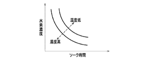
起動時水素濃度算出手段62は、燃料電池スタック10が停止してからの経過時間、いわゆるソーク時間と、冷媒の温度とから、燃料電池スタック10の起動時の水素濃度を算出する。具体的に、ここでは、マップ記憶部62aに予め記憶されたマップや関数に基づいて水素濃度を取得する。
マップ記憶部62aが記憶しているマップとしては、例えば、図3に示すようなものであり、例えば、ソーク時間と水素濃度との関係を、冷媒の温度を加味した曲線で表される関数に対応させたものを用いることができる。図3では、ソーク時間が短く、冷媒温度が低いほど、水素濃度は高くなる傾向を示しており、ソーク時間が長く、冷媒温度が高いほど、水素濃度は低くなる傾向を示している。起動時水素濃度算出手段62で算出された水素濃度は、推定水素濃度算出手段65に出力される。
このような起動時水素濃度算出手段62による水素濃度の算出は、起動直後、つまり、OCVパージが行われる前に行われる。
The startup hydrogen concentration calculating means 62 calculates the hydrogen concentration at startup of the
The map stored in the
The calculation of the hydrogen concentration by the start time hydrogen concentration calculation means 62 is performed immediately after the start, that is, before the OCV purge is performed.
ここで、ソーク時間の計測は、起動時水素濃度算出手段62に接続されたタイマ62bによって行われる。このタイマ62bは、燃料電池スタック10の駆動が停止すると、ECU60によりリセットされ、このリセットされた時刻からの経過時間を計測する。
Here, the soak time is measured by a
パージ積算量算出手段63は、燃料電池スタック10が起動されてからパージに使用された水素の積算量を算出する。具体的には、例えば、遮断弁22(図1参照)以降の圧力を図示しないセンサで検出し、この圧力値とパージ時間とからパージ積算量を求めることができる。算出されたパージ積算量は、水素濃度上昇量算出手段64に出力される。
The purge integrated amount calculation means 63 calculates the integrated amount of hydrogen used for purging after the
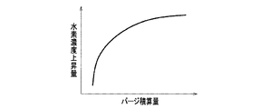
水素濃度上昇量算出手段64は、入力されたパージ積算量から水素濃度上昇量を算出する。具体的に、ここでは、マップ記憶部64aに予め記憶されたマップや関数に基づいて水素濃度上昇量を取得する。
マップ記憶部64aが記憶しているマップとしては、例えば、図4に示すような関数を用いることができる。算出された水素濃度上昇量は、推定水素濃度算出手段65に出力される。
The hydrogen concentration increase amount calculating means 64 calculates the hydrogen concentration increase amount from the input purge integrated amount. Specifically, here, the hydrogen concentration increase amount is acquired based on a map or function stored in advance in the
As the map stored in the
推定水素濃度算出手段65は、起動時水素濃度算出手段62で算出された起動時の水素濃度と、水素濃度上昇量算出手段64で算出された水素濃度上昇量とから、現在推定される水素濃度を算出する。具体的に、起動時の水素濃度に水素濃度上昇量を加算して、現在推定される水素濃度を算出する。算出された水素濃度の値は、運転制御手段61Bの水素濃度判定手段66に出力される。 The estimated hydrogen concentration calculation means 65 is a currently estimated hydrogen concentration from the hydrogen concentration at startup calculated by the startup hydrogen concentration calculation means 62 and the hydrogen concentration increase calculated by the hydrogen concentration increase calculation means 64. Is calculated. Specifically, the hydrogen concentration increase amount is added to the hydrogen concentration at the time of startup to calculate the currently estimated hydrogen concentration. The calculated hydrogen concentration value is output to the hydrogen concentration determination means 66 of the operation control means 61B.
運転制御手段61Bの水素濃度判定手段66は、算出された前記水素濃度の値が、予め設定された所定値よりも大きいか否かを判定する。つまり、OCVパージによる水素置換後の水素濃度が、所定値よりも大きくなっているか(燃料電池スタック10に負担のかからない発電が可能な水素濃度となっているか)否かを判定する。 The hydrogen concentration determination means 66 of the operation control means 61B determines whether or not the calculated hydrogen concentration value is larger than a predetermined value set in advance. That is, it is determined whether the hydrogen concentration after hydrogen replacement by the OCV purge is higher than a predetermined value (whether the hydrogen concentration is such that power generation that does not impose a burden on the fuel cell stack 10) is possible.
発電電流制御手段67は、水素濃度判定手段66による判定に基づいてVCU52を制御する。例えば、水素濃度の値(濃度値)が所定値よりも小さいときには、その水素濃度の値と検出された冷媒の温度値とから発電可能な発電電流上限値を算出する。
ここで、発電電流制御手段67は、特定された水素濃度の値が所定値より低いほど発電電流の電流値が小さくなるように、また、検出された温度値が所定値より高いほど発電電流の電流値が小さくなるように制御するようになっている。具体的に、ここでは、マップ記憶部67aに予め記憶されたマップや関数に基づいて発電電流上限値を取得する。
マップ記憶部67aが記憶しているマップとしては、例えば、図5に示すようなものであり、例えば、水素濃度と発電電流上限値との関係を、冷媒の温度を加味した直線で表される関数に対応させたものを用いることができる。図5では、水素濃度の値が所定値より低いほど、発電電流上限値は低くなる傾向を示し、発電電流の電流値が小さくなるように制御され、また、検出された温度値が所定値より高いほど、発電電流上限値は低くなる傾向を示し、発電電流の電流値が小さくなるように制御される。算出された発電電流上限値は、VCU52に出力される。
また、前記した水素濃度の値が所定値よりも大きいと水素濃度判定手段66により判定されたときには、発電電流制御手段67は、定格発電を許可する信号をVCU52に出力する。
The generated
Here, the generated current control means 67 is configured so that the current value of the generated current decreases as the specified hydrogen concentration value is lower than the predetermined value, and the generated current value increases as the detected temperature value is higher than the predetermined value. The current value is controlled to be small. Specifically, here, the generated current upper limit value is acquired based on a map or function stored in advance in the
The map stored in the
When the hydrogen
パージ制御手段68は、水素濃度判定手段66による判定に基づいてパージ弁24を制御する。例えば、水素濃度の値が所定値よりも小さいときには、パージ量が増大するように、パージ頻度(回数/時間)をそれまでよりも増やす制御を行ったり、1回あたりのパージ時間が長くなるように設定を変更したりする制御を行う。
また、前記した水素濃度の値が所定値よりも大きいと水素濃度判定手段66により判定されたときには、パージ量が増大する制御を行わず、通常のパージ量となるように制御する。
The
In addition, when the hydrogen concentration determination means 66 determines that the above-described hydrogen concentration value is larger than a predetermined value, the control is performed so that the purge amount becomes a normal purge amount without performing control to increase the purge amount.
冷媒流量調整手段69は、水素濃度判定手段66による判定に基づいてパージ弁24を制御する。例えば、水素濃度の値が所定値よりも小さいときには、冷媒の温度を低く維持して燃料電池スタック10の負担を軽くするために、流量調整弁41を開方向に制御する。
また、前記した水素濃度の値が所定値よりも大きいと水素濃度判定手段66により判定されたときには、燃料電池スタック10に負担がかからない状態であるとして、暖機運転を行うべく、流量調整弁41を閉方向に制御する。
The refrigerant flow
Further, when the hydrogen concentration determination means 66 determines that the hydrogen concentration value is larger than a predetermined value, it is determined that the
また、必要に応じて、冷媒流量調整手段69は、水素濃度判定手段66による判定に基づいてパージ弁24を制御する。例えば、水素濃度の値が所定値よりも小さいときには、冷媒の温度を低く維持して燃料電池スタック10の負担を軽くするために、切替弁43を制御して、冷媒がラジエータ42(図1参照)に通流するように設定する(ラジエータ通流モード)。
また、前記した水素濃度の値が所定値よりも大きいと水素濃度判定手段66により判定されたときには、燃料電池スタック10に負担がかからない状態であるとして、暖機運転を行うべく、切替弁43を制御して、冷媒がラジエータ42(図1参照)をバイパスして通流するように設定する(バイパスモード)。
Further, as necessary, the refrigerant flow
Further, when the hydrogen concentration determination means 66 determines that the above-described hydrogen concentration value is larger than the predetermined value, it is determined that the
≪燃料電池システムの動作≫
次に、燃料電池システム1の動作について、図6を主に参照しつつ適宜各図を参照して説明する。
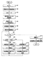
ステップS1において、IG60aがオンされると、このオン信号を検知したECU60は、起動時の各種処理を実行し、ステップS2において、制御手段61の水素濃度算出手段61Aにより、起動時の水素濃度を算出する。つまり、タイマ62bにより計測されたソーク時間、冷媒温度センサ44からの温度値に基づいて、図3から水素濃度が取得される。
≪Operation of fuel cell system≫
Next, the operation of the fuel cell system 1 will be described with reference to each drawing as appropriate with reference mainly to FIG.
When the
ステップS3において、OCVパージが実行される。ここで、OCVパージは、燃料電池スタック10が発電を行う前に、発電可能な状態かどうかを判断するために必要な手順であり、燃料電池スタック10の起動に際して、アノード内の水素をフレッシュな水素に置き換え、水素濃度を高める操作である。OCVパージは、例えば、開回路電圧(開放端電圧ともいう)を用いて判断する。このOCVは、電圧計(図示しない)から得られる電圧値Vによって判断される。また、OCVパージは、パージ弁24を開くことにより行われる。これは、ソーク中(システム停止中)にアノード系内の水素濃度が低下することがあり、水素濃度が低いと燃料電池スタック10の安定発電が行えなくなるからである。
なお、OCVチェックの完了の条件としては、例えば電圧値Vが所定電圧を超えたことにより判断することができる。
In step S3, OCV purge is executed. Here, the OCV purge is a procedure necessary for determining whether or not the
The condition for completing the OCV check can be determined, for example, when the voltage value V exceeds a predetermined voltage.
ステップS4において、OCVチェックの完了により燃料電池スタック10が発電を開始する。すなわち、ECU60は、コンタクタ54をON状態にするとともに、VCU52に対して燃料電池スタック10から電流を取り出す指令を発する(燃料電池起動手段)。
In step S4, the
ステップS5において、パージ積算量算出手段63により、燃料電池スタック10が起動されてからパージに使用された水素の積算量を算出する。
In step S5, the integrated
ステップS6において、水素濃度上昇量算出手段64により、入力されたパージ積算量から水素濃度上昇量を算出する。 In step S6, the hydrogen concentration increase amount calculating means 64 calculates the hydrogen concentration increase amount from the input purge integrated amount.
ステップS7において、推定水素濃度算出手段65は、起動時水素濃度算出手段62で算出された起動時の水素濃度と、水素濃度上昇量算出手段64で算出された水素濃度上昇量とから、現在推定される水素濃度を算出する。
In step S <b> 7, the estimated hydrogen
ステップS8において、ECU60により、暖機が完了したか否かが判定される。ここでは、燃料電池スタック10が固有する暖機完了温度(例えば、60℃以上)に、冷媒の温度値Tが到達したか否かを判定する。
In step S8, the
暖機完了温度(例えば、60℃以上)に、冷媒の温度値Tが到達していない(ステップS8:No)ときは、ステップS9において、運転制御手段61Bの水素濃度判定手段66によって、水素濃度(ステップS7で算出)の値が所定値(暖機移行水素濃度、例えば、水素濃度が95%)よりも大きいか否かを判定する。
When the temperature value T of the refrigerant has not reached the warm-up completion temperature (for example, 60 ° C. or higher) (step S8: No), the hydrogen concentration is determined by the hydrogen
水素濃度(ステップS7で算出)の値が所定値よりも小さい(ステップS9:No)ときは、ステップS10において、発電電流制御手段67により発電電流上限値を算出する。つまり、水素濃度の値と冷媒の温度値Tとから、図5に基づいて、発電可能な発電電流上限値を取得し、その取得した発電電流上限値を超えないようにVCU52を制御する。つまり、水素濃度の値が所定値より低いほど、発電電流の電流値が小さくなるように、また、検出された温度値Tが所定値より高いほど、発電電流の電流値が小さくなるようにVCU52を制御する。
When the value of the hydrogen concentration (calculated in step S7) is smaller than the predetermined value (step S9: No), the generated current upper limit value is calculated by the generated current control means 67 in step S10. That is, a power generation current upper limit value that can be generated is acquired from the hydrogen concentration value and the refrigerant temperature value T based on FIG. 5, and the
そして、ステップS11において、パージ制御手段68によりパージ量が増大するようにパージ弁24を制御する。
In step S11, the purge control means 68 controls the
さらに、ステップS12において、冷媒流量調整手段69により冷媒の温度値Tを低く維持して燃料電池スタック10の負担を軽くするために、流量調整弁41を開方向に制御する。なお、水素濃度が下がれば、冷媒の通流は、バイパスモード、ラジエータ通流モードのどちらでもよい。
その後、ステップS8以降を繰り返す。
Further, in step S12, the flow
Thereafter, step S8 and subsequent steps are repeated.
一方、前記ステップS9において、水素濃度(ステップS7で算出)が所定値よりも大きい(Yes)ときは、ステップS13において、発電電流制御手段67により、VCU52の定格発電を許可する。
On the other hand, in step S9, when the hydrogen concentration (calculated in step S7) is larger than the predetermined value (Yes), in step S13, the power generation current control means 67 permits the rated power generation of the
また、ステップS14において、パージ制御手段68により、パージ弁24を通常のパージ量に制御するとともに、ステップS15において、冷媒流量調整手段69により、燃料電池スタック10に負担がかからない状態であるとして、暖機運転を行うべく、流量調整弁41を開方向に制御する。その後、ステップS8以降を繰り返す。
In step S14, the purge control means 68 controls the
その後、ステップS8において、暖機完了温度(例えば、60℃以上)に、冷媒の温度値Tが到達した(Yes)ときは、ステップS16において、暖機を完了し、ステップS17において、冷媒流量調整手段69による流量調整弁41の制御を解除し、その後、終了する。
Thereafter, in step S8, when the temperature value T of the refrigerant reaches the warm-up completion temperature (for example, 60 ° C. or higher) (Yes), the warm-up is completed in step S16, and the refrigerant flow rate adjustment is performed in step S17. The control of the flow
以上説明した本実施形態の燃料電池システムによれば、燃料電池スタック10の暖機が完了していない場合(暖機完了温度に到達していない場合(ステップS8:No))、つまり、燃料電池スタック10の発電安定性が確保されていないときに、水素濃度の値を検出して、その水素濃度の値が所定値に到達していない低い濃度である場合(ステップS9:No)には、燃料電池スタック10の発電を制限するので、ガス置換後の、アノード系内が完全に水素に置換されていない状況において、水素濃度と燃料電池スタック10内の温度に見合った電流値で発電することができる。これにより、燃料電池スタック10の負担を軽減することができ、燃料電池スタック10の劣化を好適に抑制することができるようになる。
According to the fuel cell system of the present embodiment described above, when the warm-up of the
また、制御手段61は、特定された水素濃度の値が所定値より低く、かつ、温度値Tが所定値よりも低いときに、冷媒の通流量を増大させるように制御するので、燃料電池スタック10内の温度が低下され、ガス置換後の、アノード系内が完全に水素に置換されていない状況において反応性を低下させることができ、電極(触媒等)を保護することができる。これにより、燃料電池スタック10の劣化を好適に抑制することができるようになる。
Further, the control unit 61, the value of the specified hydrogen concentration is lower than the predetermined value, and, when the temperature value T is lower than the predetermined value, and controls so as to increase the passing flow rate of the refrigerant, the fuel cell In the situation where the temperature in the
また、制御手段61は、パージ弁24によって排出されるアノードオフガスの量を増大させるように制御するので、燃料電池スタック10内が水素で好適に置換されるようになり、燃料電池スタック10の負担が軽減されて、燃料電池スタック10の劣化を一層好適に抑制することができる。また、起動時間の短縮を図ることもできる。
Further, since the control means 61 performs control so as to increase the amount of anode off-gas discharged by the
また、制御手段61は、水素濃度の値が所定値になったときに発電電流の制限を解除するので、燃料電池スタック10から外部負荷に向けて定格で発電電流が引かれるようになる。これにより、燃料電池スタック10が劣化するのを抑制しつつ、好適な発電を行うことができる。
Further, since the control means 61 releases the limit of the generated current when the value of the hydrogen concentration reaches a predetermined value, the generated current is drawn from the
また、制御手段61は、水素濃度の値が所定値になっても、燃料電池スタック10内の温度が暖機完了温度に到達するまで、冷媒の通流量を減少させるように制限するので、暖機が促進されるようになり、燃料電池スタック10が劣化するのを抑制しつつ、好適な発電を行うことができる。
Further, the control unit 61, even if the value of the hydrogen concentration reaches a predetermined value, until the temperature of the
また、制御手段61は、燃料電池スタック10内の温度が暖機完了温度に到達したときに、冷媒の通流量の制限を解除するので、燃料電池スタック10が劣化するのを抑制しつつ、好適な発電を行うことができる。
Further, the control unit 61, when the temperature of the
前記した実施形態では、流量調整弁41を主として用いて、冷媒の流量を調整するようにしたが、これに限られることはなく、冷媒ポンプ40の回転数をECU60の制御によって適宜制御することにより、流量調整弁41を用いたときと同様に、冷媒の流量を調整するようにしてもよい。
In the above-described embodiment, the flow rate of the refrigerant is adjusted mainly using the flow
また、流量調整弁41の開閉制御、切替弁43の切替制御、および冷媒ポンプ40の回転数の制御を単独で、あるいは複数組み合わせることにより、冷媒の流量を調整するようにしてもよい。
The flow rate of the refrigerant may be adjusted by singly or in combination of the opening / closing control of the flow
また、冷媒温度センサ44に代えて、膜電極接合体(MEA)の温度を直接測定して、これを温度値としてもよい。
Further, instead of the
また、前記実施形態では、水素濃度算出手段61Aにより水素濃度を算出することで特定するようにしたが、これに限られることはなく、水素濃度センサを設けて水素濃度を検出するようにしてもよい。また、カソード系に酸素濃度センサを設けて、その値から水素濃度を推定することで特定するようにしてもよい。 In the above embodiment, the hydrogen concentration is calculated by calculating the hydrogen concentration using the hydrogen concentration calculation means 61A. However, the present invention is not limited to this, and a hydrogen concentration sensor may be provided to detect the hydrogen concentration. Good. Alternatively, an oxygen concentration sensor may be provided in the cathode system, and the hydrogen concentration may be estimated based on the value.
1 燃料電池システム
10 燃料電池スタック
24 パージ弁(パージ手段)
41 流量調整弁
43 切替弁
44 冷媒温度センサ
52 VCU
55 電流センサ
60 ECU
61 制御手段
DESCRIPTION OF SYMBOLS 1
41
55
61 Control means
Claims (10)
前記燃料ガスを前記燃料電池に供給する燃料ガス供給手段と、
前記燃料電池の起動時に、前記燃料ガスが流通する燃料ガス流通路内を前記燃料ガスで置換する置換手段と、
前記置換手段によりガス置換を実行後、前記燃料電池の発電を開始する燃料電池起動手段と、
前記燃料電池内の前記燃料ガスの濃度を求める濃度特定手段と、
前記燃料電池内の温度を検出する温度検出手段と、を有する燃料電池システムであって、
前記燃料電池システムの制御を行う制御手段をさらに有し、
前記制御手段は、
前記燃料電池起動手段により前記燃料電池の発電が開始された後に、前記温度検出手段によって検出された前記燃料電池内の温度が、暖機が完了した暖機完了温度に到達しているか否かを判定し、
暖機完了温度に到達している場合には、前記燃料電池の暖機が完了していると判断し、
暖機完了温度に到達していない場合には、特定された前記燃料ガスの濃度値が所定値に到達しているか否かを判定し、
前記燃料ガスの濃度値が所定値に到達している場合には、前記燃料電池の定格発電を許可し、到達していない場合には、前記燃料電池の発電電流を制限し、
発電電流を制限する制御時に、特定された前記濃度値が低いほど発電電流の電流値が小さくなるように制御し、検出された前記燃料電池内の温度が高いほど発電電流の電流値が小さくなるように制御することを特徴とする燃料電池システム。 A fuel cell that generates electricity by a reaction between the fuel gas and the oxidant gas;
Fuel gas supply means for supplying the fuel gas to the fuel cell;
Replacement means for replacing the inside of the fuel gas flow path through which the fuel gas flows with the fuel gas when the fuel cell is activated;
Fuel cell starting means for starting power generation of the fuel cell after performing gas replacement by the replacement means;
A concentration specifying means for determining the concentration of the fuel gas in the fuel cell;
A temperature detecting means for detecting the temperature in the fuel cell, and a fuel cell system comprising:
A control means for controlling the fuel cell system;
The control means includes
Whether or not the temperature in the fuel cell detected by the temperature detection means has reached the warm-up completion temperature at which the warm-up has been completed after the fuel cell start-up means starts the power generation of the fuel cell. Judgment,
If the warm-up completion temperature has been reached, it is determined that the fuel cell has been warmed-up,
When the warm-up completion temperature has not been reached, it is determined whether or not the specified concentration value of the fuel gas has reached a predetermined value,
If the concentration value of the fuel gas has reached a predetermined value, the rated power generation of the fuel cell is permitted, and if not, the power generation current of the fuel cell is limited,
When control for limiting the generated current, and controlled so that the current value of the generator current the lower the density values specified decreases, the current value of the temperature in said detected fuel cell The higher generated current A fuel cell system that is controlled to be small.
前記燃料ガスを前記燃料電池に供給する燃料ガス供給手段と、
前記燃料電池の起動時に、前記燃料ガスが流通する燃料ガス流通路内を前記燃料ガスで置換する置換手段と、
前記置換手段によりガス置換を実行後、前記燃料電池の発電を開始する燃料電池起動手段と、
前記燃料電池内の前記燃料ガスの濃度を求める濃度特定手段と、
前記燃料電池内の温度を検出する温度検出手段と、を有する燃料電池システムであって、
前記燃料電池システムの制御を行う制御手段をさらに有し、
前記制御手段は、
前記燃料電池起動手段により前記燃料電池の発電が開始された後に、前記温度検出手段によって検出された前記燃料電池内の温度が、暖機が完了した暖機完了温度に到達しているか否かを判定し、
暖機完了温度に到達している場合には、前記燃料電池の暖機が完了していると判断し、
暖機完了温度に到達していない場合には、特定された前記燃料ガスの濃度値が所定値に到達しているか否かを判定し、
前記燃料ガスの濃度値が所定値に到達している場合には、前記燃料電池の定格発電を許可し、到達していない場合には、前記燃料電池の発電電流を制限し、
発電電流を制限する制御時に、前記燃料電池内を通流する冷媒の通流量を増大させるように制御することを特徴とする燃料電池システム。 A fuel cell that generates electricity by a reaction between the fuel gas and the oxidant gas;
Fuel gas supply means for supplying the fuel gas to the fuel cell;
Replacement means for replacing the inside of the fuel gas flow path through which the fuel gas flows with the fuel gas when the fuel cell is activated;
Fuel cell starting means for starting power generation of the fuel cell after performing gas replacement by the replacement means;
A concentration specifying means for determining the concentration of the fuel gas in the fuel cell;
A fuel cell system having a temperature detecting means that detect the temperature in the fuel cell,
A control means for controlling the fuel cell system;
The control means includes
Whether or not the temperature in the fuel cell detected by the temperature detection means has reached the warm-up completion temperature at which the warm-up has been completed after the fuel cell start-up means starts the power generation of the fuel cell. Judgment,
If the warm-up completion temperature has been reached, it is determined that the fuel cell has been warmed-up,
When the warm-up completion temperature has not been reached, it is determined whether or not the specified concentration value of the fuel gas has reached a predetermined value,
If the concentration value of the fuel gas has reached a predetermined value, the rated power generation of the fuel cell is permitted, and if not, the power generation current of the fuel cell is limited,
A fuel cell system, wherein control is performed so as to increase a flow rate of a refrigerant flowing through the fuel cell at the time of control for limiting a generated current .
前記制御手段は、発電電流を制限する制御時に、前記パージ手段によって排出される燃料ガスの量を増大させるように制御することを特徴とする請求項1から請求項5のいずれか1項に記載の燃料電池システム。 Purge means for purging the fuel gas discharged from the fuel cell;
6. The control unit according to claim 1, wherein the control unit performs control so as to increase an amount of fuel gas discharged by the purge unit during control for limiting the generated current. 7. Fuel cell system.
前記温度検出手段は、前記冷媒温度検出手段によって検出された前記冷媒の温度を前記燃料電池内の温度とすることを特徴とする請求項1から請求項7のいずれか1項に記載の燃料電池システム。The fuel cell according to any one of claims 1 to 7, wherein the temperature detection means uses the temperature of the refrigerant detected by the refrigerant temperature detection means as a temperature inside the fuel cell. system.
前記制御手段は、前記燃料電池の定格発電を許可する制御時に、前記パージ手段によって排出される燃料ガスの量を、前記燃料電池の発電電流を制限する制御時よりも少ない通常量としてパージを行った上で前記冷媒の通流量を減少させるように制御することを特徴とする請求項4または請求項5に記載の燃料電池システム。The control means performs purging by setting the amount of fuel gas discharged by the purge means at a normal amount smaller than that at the time of control for limiting the power generation current of the fuel cell during control for permitting rated power generation of the fuel cell. 6. The fuel cell system according to claim 4, wherein the control is performed so that the flow rate of the refrigerant is reduced.
前記起動時水素濃度算出手段により求められた水素濃度は、経過時間が長く冷媒の温度が高いほど水素濃度が低くなることを特徴とする請求項8に記載の燃料電池システム。9. The fuel cell system according to claim 8, wherein the hydrogen concentration obtained by the start-up hydrogen concentration calculating means is such that the hydrogen concentration decreases as the elapsed time is longer and the temperature of the refrigerant is higher.
Priority Applications (1)
| Application Number | Priority Date | Filing Date | Title |
|---|---|---|---|
| JP2008149694A JP5113634B2 (en) | 2008-06-06 | 2008-06-06 | Fuel cell system |
Applications Claiming Priority (1)
| Application Number | Priority Date | Filing Date | Title |
|---|---|---|---|
| JP2008149694A JP5113634B2 (en) | 2008-06-06 | 2008-06-06 | Fuel cell system |
Publications (2)
| Publication Number | Publication Date |
|---|---|
| JP2009295505A JP2009295505A (en) | 2009-12-17 |
| JP5113634B2 true JP5113634B2 (en) | 2013-01-09 |
Family
ID=41543499
Family Applications (1)
| Application Number | Title | Priority Date | Filing Date |
|---|---|---|---|
| JP2008149694A Expired - Fee Related JP5113634B2 (en) | 2008-06-06 | 2008-06-06 | Fuel cell system |
Country Status (1)
| Country | Link |
|---|---|
| JP (1) | JP5113634B2 (en) |
Cited By (2)
| Publication number | Priority date | Publication date | Assignee | Title |
|---|---|---|---|---|
| US10707506B2 (en) | 2017-07-03 | 2020-07-07 | Hyundai Motor Company | Hydrogen supply method for fuel cell system |
| US10930945B2 (en) | 2017-10-17 | 2021-02-23 | Hyundai Motor Company | Fuel cell system and control method thereof |
Families Citing this family (5)
| Publication number | Priority date | Publication date | Assignee | Title |
|---|---|---|---|---|
| US20140272645A1 (en) * | 2013-03-15 | 2014-09-18 | SOCIéTé BIC | Fuel cell dc-dc converter |
| KR101679970B1 (en) * | 2015-05-11 | 2016-11-25 | 현대자동차주식회사 | Apparatus for controlling purge valve of fuel cell vehicle and method thereof |
| JP6451668B2 (en) * | 2016-03-04 | 2019-01-16 | トヨタ自動車株式会社 | FUEL CELL SYSTEM AND CONTROL METHOD FOR FUEL CELL SYSTEM |
| JP6857846B2 (en) * | 2016-06-29 | 2021-04-14 | パナソニックIpマネジメント株式会社 | Fuel cell system and how to operate it |
| JP6160757B1 (en) * | 2016-09-16 | 2017-07-12 | 富士電機株式会社 | Fuel cell system and operation method thereof |
Family Cites Families (5)
| Publication number | Priority date | Publication date | Assignee | Title |
|---|---|---|---|---|
| JP4106960B2 (en) * | 2002-05-14 | 2008-06-25 | 日産自動車株式会社 | Fuel cell system |
| JP2004172026A (en) * | 2002-11-22 | 2004-06-17 | Toyota Motor Corp | Operation control of fuel cell system |
| JP4575693B2 (en) * | 2004-03-30 | 2010-11-04 | トヨタ自動車株式会社 | Fuel cell system |
| JP4796361B2 (en) * | 2005-09-07 | 2011-10-19 | 本田技研工業株式会社 | Fuel cell system |
| JP4997804B2 (en) * | 2006-03-27 | 2012-08-08 | 日産自動車株式会社 | Fuel cell system |
-
2008
- 2008-06-06 JP JP2008149694A patent/JP5113634B2/en not_active Expired - Fee Related
Cited By (2)
| Publication number | Priority date | Publication date | Assignee | Title |
|---|---|---|---|---|
| US10707506B2 (en) | 2017-07-03 | 2020-07-07 | Hyundai Motor Company | Hydrogen supply method for fuel cell system |
| US10930945B2 (en) | 2017-10-17 | 2021-02-23 | Hyundai Motor Company | Fuel cell system and control method thereof |
Also Published As
| Publication number | Publication date |
|---|---|
| JP2009295505A (en) | 2009-12-17 |
Similar Documents
| Publication | Publication Date | Title |
|---|---|---|
| JP4591721B2 (en) | Fuel cell system | |
| CN110767924B (en) | Fuel cell system | |
| JP4644064B2 (en) | Fuel cell system | |
| JP5476408B2 (en) | Fuel cell system | |
| JP5576902B2 (en) | Fuel cell system and operation method thereof | |
| US9093679B2 (en) | Method of shutting down fuel cell system | |
| US9225028B2 (en) | Fuel cell system | |
| JP5155734B2 (en) | Fuel cell system and operation method thereof | |
| US20080248351A1 (en) | Fuel Cell System | |
| JP5113634B2 (en) | Fuel cell system | |
| JP2013206625A (en) | Fuel cell system | |
| JP4814930B2 (en) | Fuel cell system | |
| JP6137124B2 (en) | Fuel cell system and vehicle equipped with fuel cell | |
| JP5061453B2 (en) | Fuel cell system | |
| US8148033B2 (en) | Fuel cell system with suppressed noise and vibration | |
| JP5314332B2 (en) | Fuel cell system and operation method thereof | |
| JP2007141744A (en) | Fuel cell system | |
| US8092947B1 (en) | Fuel cell system | |
| JP5097016B2 (en) | Fuel cell system and method for determining open / close state of shut-off valve | |
| JP5326220B2 (en) | Fuel cell system and hybrid vehicle system | |
| JP2013232407A (en) | Fuel cell system and fuel cell system purge control method | |
| JP5144152B2 (en) | Discharge system | |
| JP5319160B2 (en) | Fuel cell system | |
| JP2005129243A (en) | Fuel cell system and operation method of fuel cell | |
| JP2007149511A (en) | Fuel cell system and starting method therefor |
Legal Events
| Date | Code | Title | Description |
|---|---|---|---|
| A977 | Report on retrieval |
Free format text: JAPANESE INTERMEDIATE CODE: A971007 Effective date: 20120228 |
|
| A131 | Notification of reasons for refusal |
Free format text: JAPANESE INTERMEDIATE CODE: A131 Effective date: 20120313 |
|
| A521 | Written amendment |
Free format text: JAPANESE INTERMEDIATE CODE: A523 Effective date: 20120514 |
|
| TRDD | Decision of grant or rejection written | ||
| A01 | Written decision to grant a patent or to grant a registration (utility model) |
Free format text: JAPANESE INTERMEDIATE CODE: A01 Effective date: 20121002 |
|
| A01 | Written decision to grant a patent or to grant a registration (utility model) |
Free format text: JAPANESE INTERMEDIATE CODE: A01 |
|
| A61 | First payment of annual fees (during grant procedure) |
Free format text: JAPANESE INTERMEDIATE CODE: A61 Effective date: 20121012 |
|
| FPAY | Renewal fee payment (event date is renewal date of database) |
Free format text: PAYMENT UNTIL: 20151019 Year of fee payment: 3 |
|
| R150 | Certificate of patent or registration of utility model |
Ref document number: 5113634 Country of ref document: JP Free format text: JAPANESE INTERMEDIATE CODE: R150 Free format text: JAPANESE INTERMEDIATE CODE: R150 |
|
| LAPS | Cancellation because of no payment of annual fees |