JP5073796B2 - Laser oscillator controller - Google Patents
Laser oscillator controller Download PDFInfo
- Publication number
- JP5073796B2 JP5073796B2 JP2010186277A JP2010186277A JP5073796B2 JP 5073796 B2 JP5073796 B2 JP 5073796B2 JP 2010186277 A JP2010186277 A JP 2010186277A JP 2010186277 A JP2010186277 A JP 2010186277A JP 5073796 B2 JP5073796 B2 JP 5073796B2
- Authority
- JP
- Japan
- Prior art keywords
- signal
- laser oscillator
- controller
- communication line
- stop
- Prior art date
- Legal status (The legal status is an assumption and is not a legal conclusion. Google has not performed a legal analysis and makes no representation as to the accuracy of the status listed.)
- Expired - Fee Related
Links
Images
Classifications
-
- H—ELECTRICITY
- H01—ELECTRIC ELEMENTS
- H01S—DEVICES USING THE PROCESS OF LIGHT AMPLIFICATION BY STIMULATED EMISSION OF RADIATION [LASER] TO AMPLIFY OR GENERATE LIGHT; DEVICES USING STIMULATED EMISSION OF ELECTROMAGNETIC RADIATION IN WAVE RANGES OTHER THAN OPTICAL
- H01S3/00—Lasers, i.e. devices using stimulated emission of electromagnetic radiation in the infrared, visible or ultraviolet wave range
- H01S3/09—Processes or apparatus for excitation, e.g. pumping
- H01S3/097—Processes or apparatus for excitation, e.g. pumping by gas discharge of a gas laser
- H01S3/09702—Details of the driver electronics and electric discharge circuits
-
- B—PERFORMING OPERATIONS; TRANSPORTING
- B23—MACHINE TOOLS; METAL-WORKING NOT OTHERWISE PROVIDED FOR
- B23K—SOLDERING OR UNSOLDERING; WELDING; CLADDING OR PLATING BY SOLDERING OR WELDING; CUTTING BY APPLYING HEAT LOCALLY, e.g. FLAME CUTTING; WORKING BY LASER BEAM
- B23K26/00—Working by laser beam, e.g. welding, cutting or boring
- B23K26/70—Auxiliary operations or equipment
- B23K26/702—Auxiliary equipment
-
- G—PHYSICS
- G05—CONTROLLING; REGULATING
- G05B—CONTROL OR REGULATING SYSTEMS IN GENERAL; FUNCTIONAL ELEMENTS OF SUCH SYSTEMS; MONITORING OR TESTING ARRANGEMENTS FOR SUCH SYSTEMS OR ELEMENTS
- G05B19/00—Program-control systems
- G05B19/02—Program-control systems electric
- G05B19/04—Program control other than numerical control, i.e. in sequence controllers or logic controllers
- G05B19/042—Program control other than numerical control, i.e. in sequence controllers or logic controllers using digital processors
- G05B19/0428—Safety, monitoring
-
- H—ELECTRICITY
- H01—ELECTRIC ELEMENTS
- H01S—DEVICES USING THE PROCESS OF LIGHT AMPLIFICATION BY STIMULATED EMISSION OF RADIATION [LASER] TO AMPLIFY OR GENERATE LIGHT; DEVICES USING STIMULATED EMISSION OF ELECTROMAGNETIC RADIATION IN WAVE RANGES OTHER THAN OPTICAL
- H01S3/00—Lasers, i.e. devices using stimulated emission of electromagnetic radiation in the infrared, visible or ultraviolet wave range
- H01S3/23—Arrangements of two or more lasers not provided for in groups H01S3/02 - H01S3/22, e.g. tandem arrangements of separate active media
- H01S3/2383—Parallel arrangements
Landscapes
- Engineering & Computer Science (AREA)
- Physics & Mathematics (AREA)
- Optics & Photonics (AREA)
- Electromagnetism (AREA)
- Plasma & Fusion (AREA)
- General Physics & Mathematics (AREA)
- Microelectronics & Electronic Packaging (AREA)
- Automation & Control Theory (AREA)
- Mechanical Engineering (AREA)
- Lasers (AREA)
- Numerical Control (AREA)
- Semiconductor Lasers (AREA)
- Laser Surgery Devices (AREA)
Description
本発明は、コントローラとの通信によりレーザ発振器を制御するレーザ発振器制御装置に関する。 The present invention relates to a laser oscillator control device that controls a laser oscillator by communicating with a controller.
この種のレーザ発振器制御装置として、従来、制御プログラムの実行異常を検出するウォッチドッグタイマを備え、制御プログラムに異常が発生した場合に、レーザ光線照射手段のゲート信号を遮断して、レーザ照射を停止させるようにした装置が知られている(例えば特許文献1参照)。また、コントローラとの通信により制御されるI/Oモジュールを有する装置において、コントローラからの周期的な信号の有無をI/Oモジュール内に備えたウォッチドッグタイマで検出し、周期的な信号がなくなるとI/Oモジュールからの出力を停止させるようにした装置が知られている(例えば特許文献2参照)。 Conventionally, this type of laser oscillator control device has been equipped with a watchdog timer that detects abnormalities in the execution of the control program. When an abnormality occurs in the control program, the gate signal of the laser beam irradiating means is shut off to perform laser irradiation. An apparatus that is stopped is known (see, for example, Patent Document 1). Further, in an apparatus having an I / O module controlled by communication with a controller, the presence or absence of a periodic signal from the controller is detected by a watchdog timer provided in the I / O module, and the periodic signal disappears. And an apparatus that stops output from the I / O module is known (see, for example, Patent Document 2).
ところで、コントローラとの通信によりレーザ発振器を制御する場合には、レーザ出力データ、レーザガス圧のデータ、励起用電源出力データ等、レーザ発振器の動作状態を表す状態信号がレーザ発振器からコントローラに送信され、この状態信号に基づきコントローラがレーザ発振器をフィードバック制御する。したがって、レーザ発振器からの信号の送信に異常があると、コントローラがレーザ発振器を適切に制御できなくなる。 By the way, when controlling the laser oscillator by communication with the controller, a status signal indicating the operating state of the laser oscillator, such as laser output data, laser gas pressure data, excitation power output data, is transmitted from the laser oscillator to the controller. Based on this status signal, the controller feedback-controls the laser oscillator. Therefore, if there is an abnormality in the signal transmission from the laser oscillator, the controller cannot properly control the laser oscillator.
しかしながら、上記特許文献1,2記載の装置は、コントローラから出力される信号の異常を検出するものであり、レーザ発振器からコントローラに送信される信号の異常を検出することはできない。したがって、レーザ発振器からの送信に異常があった場合に、レーザ発振器が不所望に動作するおそれがある。
However, the devices described in
本発明は、送信部および受信部を有するコントローラと、送信部および受信部を有し、通信ラインを介してコントローラと通信するレーザ発振器とを備え、レーザ発振器からコントローラに送信されたレーザ発振器の動作状態を表す状態信号に基づいて、コントローラからレーザ発振器に制御信号を出力するレーザ発振器制御装置であって、通信ラインは、第1の通信ラインと第2の通信ラインとを有し、コントローラは、所定周期で変化する交番信号を生成し、この交番信号を第1の通信ラインおよび第2の通信ラインを介してそれぞれレーザ発振器に送信する交番信号送信回路を有し、レーザ発振器は、第1の通信ラインおよび第2の通信ラインを介して送信されたコントローラからの交番信号をそれぞれ戻り信号として第1の通信ラインおよび第2の通信ラインを介してそれぞれコントローラに送信する戻り信号送信回路を有し、さらにコントローラは、第1の通信ラインおよび第2の通信ラインを介してそれぞれ送信されたレーザ発振器からの戻り信号を監視し、戻り信号が異常であると判定すると、レーザ発振器によるレーザ照射を停止するための停止制御信号を出力する監視回路と、監視回路からの停止制御信号をレーザ発振器に送信する停止制御信号送信回路とを有し、さらにレーザ発振器は、停止制御信号を受信すると、レーザ発振器によるレーザ照射を停止させる照射停止信号を出力する停止信号出力回路を有し、停止制御信号送信回路は、第1の通信ラインを介して送信された戻り信号に基づく監視回路からの停止制御信号を、第2の通信ラインを介してレーザ発振器に送信する一方、第2の通信ラインを介して送信された戻り信号に基づく監視回路からの停止制御信号を、第1の通信ラインを介してレーザ発振器に送信することを特徴とする。 The present invention comprises a controller having a transmitter and a receiver, and a laser oscillator having a transmitter and a receiver, and communicating with the controller via a communication line, and the operation of the laser oscillator transmitted from the laser oscillator to the controller A laser oscillator control device that outputs a control signal from a controller to a laser oscillator based on a state signal representing a state, wherein the communication line includes a first communication line and a second communication line, and the controller includes: An alternating signal transmitting circuit that generates an alternating signal that changes at a predetermined cycle and transmits the alternating signal to the laser oscillator via the first communication line and the second communication line, respectively , the first communication line is transmitted through the communication line and a second communication line the alternating signal from the controller as each return signal And have respective return signal transmitting circuit for transmitting to the controller via the second communication line, and further the controller, the return signal from the laser oscillator are respectively transmitted through the first communication line and a second communication line When a return signal is determined to be abnormal, a monitoring circuit that outputs a stop control signal for stopping laser irradiation by the laser oscillator, and a stop control signal that transmits a stop control signal from the monitoring circuit to the laser oscillator have a transmission circuit, the further laser oscillator receives a stop control signal has a stop signal output circuit for outputting an irradiation stop signal to stop the laser irradiation by the laser oscillator, the stop control signal transmission circuit includes a first A stop control signal from the monitoring circuit based on the return signal transmitted through the communication line of the second communication line is transmitted via the second communication line. While it is transmitting to the oscillator, and transmits the stop control signal from the monitoring circuit based on the transmitted return signal through a second communication line, the laser oscillator via the first communication line.
本発明によれば、コントローラがレーザ発振器からの戻り信号を監視し、戻り信号が異常であると判定すると、停止制御信号を出力するようにしたので、レーザ発振器からの送信に異常があった場合のレーザ発振器の不所望な動作を防止できる。 According to the present invention, when the controller monitors the return signal from the laser oscillator and determines that the return signal is abnormal, it outputs a stop control signal. Undesirable operation of the laser oscillator can be prevented.
−第1の実施の形態−
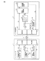
以下、図1、図2を参照して本発明の第1の実施の形態について説明する。図1は、本発明の第1の実施の形態に係るレーザ発振器制御装置の全体構成を示す図である。このレーザ発振器制御装置は、コントローラ1とレーザ発振器2とを有し、両者はシリアル通信用の通信ケーブル3を介して互いに通信可能に接続されている。
-First embodiment-
Hereinafter, a first embodiment of the present invention will be described with reference to FIGS. FIG. 1 is a diagram showing an overall configuration of a laser oscillator control device according to a first embodiment of the present invention. This laser oscillator control device has a
図1に示すように、コントローラ1は、レーザ発振器2に信号を送信する送信部11と、レーザ発振器2からの信号を受信する受信部12とを有する。同様に、レーザ発振器2は、コントローラ1に信号を送信する送信部21と、コントローラ1からの信号を受信する受信部22とを有する。各送信部11,21は、パラレル信号をシリアル信号に変換する変換回路を有し、各受信部12,22は、シリアル信号をパラレル信号に変換する変換回路を有する。
As illustrated in FIG. 1, the
コントローラ1は、CPU,ROM,RAM,その他の周辺回路などを有する演算処理装置を含んで構成され、レーザ発振器2の制御用の制御信号S1を出力する制御信号出力部13と、交番信号S2を生成する交番信号生成部14と、交番信号S2に対応したレーザ発振器2からの戻り信号S3を監視する信号監視部15とを有する。
The
制御信号出力部13には、受信部12で受信されたレーザ発振器2の動作状態を表す状態信号S4、例えばレーザ出力データ、レーザガス圧のデータ、励起用電源出力データ等の信号が入力される。制御信号出力部13は、これらの入力信号に基づいて送信部11に制御信号S1を出力し、レーザ発振器2が所定の動作を実行するようにレーザ発振器2をフィードバック制御する。
The control
交番信号生成部14は、CPUのクロック信号に応じて発振する発振回路を有し、図示のように所定周期でオンオフ的(パルス状)に変化する交番信号S2を生成して、この交番信号S2を送信部11に出力する。コントローラ1が正常に動作していれば、交番信号生成部14から交番信号S2が出力され続け、コントローラ1(CPU)の動作が異常になると、交番信号S2の出力が停止する。
The alternating
信号監視部15は、レーザ発振器2からの戻り信号S3を監視する。戻り信号S3は、図示のように交番信号S2に対応して周期的に変化(交番)する信号であり、信号監視部15では、戻り信号S3が交番する周期を監視し、戻り信号S3が異常であるか否かを判定する。例えば、予め定めた所定時間を経過しても戻り信号S3の交番が検出されない場合に、戻り信号S3が異常であると判定する。戻り信号S3が異常であると判定されると、信号監視部15は交番信号生成部14に停止信号S5を出力する。停止信号S5が出力されると、交番信号生成部14は交番信号S2の出力を停止する。
The
レーザ発振器2は、コントローラ1からの制御信号S1によりレーザ発振器本体23の駆動を制御する駆動回路部24と、受信部22で受信した交番信号S2を監視するウォッチドッグタイマ25と、交番信号S2に対応した戻り信号S3を生成する戻り信号生成部26とを有する。
The
レーザ発振器本体23は、例えば放電管と、放電管の両側に配置された一対のミラーとにより光共振器を構成する周知のものであり、放電励起用の電源が起動されて放電管の電極に高周波電圧が印加されると放電が発生し、放電管内の媒質ガスが励起され、光共振器からレーザ光が出力される。光共振器のレーザ出力部には、レーザ光を光学的に遮断または通過させるシャッタが設けられている。
The laser oscillator
駆動回路部24は、コントローラ1からの制御信号S1に応じてレーザ発振器本体23に制御信号を出力し、レーザ発振器本体23における放電のオンオフ、放電電圧の大きさ、シャッタの開閉等、レーザ発振器本体23の動作を制御する。レーザ発振器本体23の動作状態を表す状態信号S4は、コントローラ1のフィードバック制御に供するために送信部21に出力される。
The
ウォッチドッグタイマ25は、交番信号S2のパルスが入力される度にタイマをリセットする。リセット後に予め定めた所定時間t0を経過しても交番信号S2のパルスの入力がないとき、ウォッチドッグタイマ25はタイムアップし、駆動回路部24に停止信号S6を出力する。この停止信号S6により駆動回路部24は、レーザ発振器本体23の放電を停止するとともに、レーザ出力部のシャッタを閉じ、レーザ発振器2のレーザ照射を停止させる。
The
戻り信号生成部26は、交番信号S2に対応して周期的に変化する戻り信号S3を生成する。例えば、戻り信号生成部26では交番信号S2の信号線と戻り信号S3の信号線を短絡し、交番信号S2をそのまま戻り信号S3として送信部21に出力し、コントローラ1に送信する。
The
第1の実施の形態に係るレーザ発振器制御装置の主要な動作を説明する。コントローラ1のCPUに異常がなく、レーザ発振器2から送信される信号にも異常がなければ、レーザ発振器2から交番信号S1に対応した戻り信号S3がコントローラ1に送信される。この場合、信号監視部15は戻り信号S3が正常状態であると判定するため、交番信号生成部14で生成された交番信号S2がレーザ発振器2に送信され続け、ウォッチドッグタイマ25が繰り返しリセットされる。したがって、ウォッチドッグタイマ25から駆動回路部24に停止信号S6は出力されず、コントローラ1はレーザ発振器本体23の状態信号S4に応じた制御信号S1を出力し、レーザ発振器2を適切にフィードバック制御する。
The main operation of the laser oscillator control device according to the first embodiment will be described. If there is no abnormality in the CPU of the
これに対し、レーザ発振器2の送信部21または受信部22における通信状態に異常が生じると、戻り信号生成部26で正常状態の戻り信号S3が生成されず、あるいは送信部21から戻り信号S3が正常状態のまま送信されない。このため、信号監視部15は、戻り信号S3の交番周期が異常であると判定し、交番信号生成部14に停止信号S5を出力する。停止信号S5が出力されると、交番信号生成部14からの交番信号S2の出力が停止し、ウォッチドッグタイマ25はタイムアップして、駆動回路部24に停止信号S6を出力する。
On the other hand, if an abnormality occurs in the communication state in the
これにより、レーザ発振器本体23の放電が停止されるとともに、レーザ出力部のシャッタが閉じられ、レーザ発振器2の動作が停止される。レーザ発振器2の通信状態に異常が生じた場合には、戻り信号S3だけでなくレーザ発振器本体23の状態信号S4もコントローラ1に正常に送信されないが、この場合に、レーザ発振器2の動作が停止されることで、レーザ発振器2の誤動作を防止できる。なお、コントローラ1のCPUに異常が生じた場合には、交番信号S2のパルスが出力されないため、ウォッチドッグタイマ25が同様にタイムアップし、レーザ発振器2の動作が停止される。
Thereby, the discharge of the
第1の実施の形態によれば以下のような作用効果を得ることができる。
(1)コントローラ1に設けられた交番信号生成部14により、交番信号S2を生成してレーザ発振器2に送信し、レーザ発振器2に設けられた戻り信号生成部26により、コントローラ1からの交番信号S2に対応した戻り信号S3を生成してコントローラ1に送信し、さらにコントローラ1に設けられた信号監視部15により、レーザ発振器2からの戻り信号S3を監視し、戻り信号S3が異常であると判定すると、交番信号生成部14に停止信号S5を出力して交番信号S2の出力を停止するようにした。これによりレーザ発振器2の通信状態に異常が発生した場合に、レーザ発振器2のウォッチドッグタイマ25がタイムアップして、レーザ発振器2の動作が停止され、レーザ発振器2の不所望な動作を防止できる。
According to the first embodiment, the following operational effects can be obtained.
(1) The alternating
(2)レーザ発振器2に、コントローラ1からの交番信号S2により作動するウォッチドッグタイマ25を設けるようにしたので、コントローラ1の異常時にもレーザ発振器2の動作を停止できる。
(3)コントローラ1の異常時およびレーザ発振器2の異常時に、それぞれ共通のウォッチドッグタイマ25を用いてレーザ発振器2の動作を停止させるので、部品構成を簡素化できる。
(2) Since the
(3) Since the operation of the
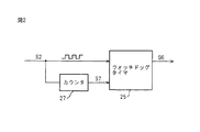
なお、以上では、コントローラ1の交番信号生成部14で交番信号S2を生成するようにしたが、コントローラ1の起動初期においては、動作が不安定となり、交番信号S2の交番周期が一定とならず、レーザ発振器2で通信異常を誤検知してしまうおそれがある。そこで、図2に示すように、レーザ発振器2に、交番信号S2の交番回数をカウンタするカウンタ27を設け、コントローラ1の起動後に交番回数が所定回数に達すると、カウンタ27から駆動開始信号S7を出力し、ウォッチドッグタイマ25に交番信号S2の監視を開始させるようにしてもよい。これにより通信状態が安定してから交番信号S2の監視が行われるため、通信異常の誤検知を防止できる。
In the above, the alternating
−第2の実施の形態−
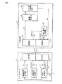
図3、図4を参照して本発明の第2の実施の形態について説明する。第2の実施の形態では、戻り信号S3の異常時に、その戻り信号S3が送信される通信ケーブル3を介さずに、コントローラ1からレーザ発振器2に停止信号を出力する。図3は、本発明の第2の実施の形態に係るレーザ発振器制御装置の全体構成を示す図である。なお、図1と同一の箇所には同一の符号を付し、以下では第1の実施の形態との相違点を主に説明する。
-Second Embodiment-
A second embodiment of the present invention will be described with reference to FIGS. In the second embodiment, when the return signal S3 is abnormal, a stop signal is output from the
図3に示すように、レーザ発振器2にウォッチドッグタイマ25(図1)は設けられず、コントローラ1からの交番信号S2は、戻り信号生成部26を介して戻り信号S3とされて送信部21に出力される。コントローラ1の信号監視部15は、レーザ発振器2からの戻り信号S3の異常の有無を判定し、戻り信号S3が異常であると判定されると、交番信号生成部14以外に停止信号S5を出力する。この停止信号S5は、レーザ発振器2によるレーザ照射を停止させるための制御信号であり、戻り信号S3が送信された通信ケーブル3を介さずに信号監視部15から出力される。なお、レーザ発振器2に第1の実施の形態と同様、ウォッチドッグタイマ25を設けてもよい。
As shown in FIG. 3, the watchdog timer 25 (FIG. 1) is not provided in the
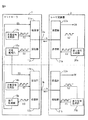
図4は、図3の停止信号S5の出力形態を含む、レーザ発振器制御装置の全体構成を示す図である。なお、図4では、制御信号出力部13とレーザ発振器本体23と駆動回路部24の図示を省略している。
FIG. 4 is a diagram showing the overall configuration of the laser oscillator control device including the output form of the stop signal S5 of FIG. In FIG. 4, the control
図4では、図3の制御構成を2系統設けて制御装置全体を構成している。すなわち、コントローラ1には、一対の送信部11a,11bと一対の受信部12a,12bと一対の信号生成部14a,14bと一対の信号監視部15a,15bとがそれぞれ設けられ、レーザ発振器2には、一対の送信部21a,21bと一対の受信部22a,22bと一対の戻り信号生成部26a,26bとがそれぞれ設けられている。コントローラ1の送受信部11a,12aとレーザ発振器2の送受信部21a,22aとは第1通信ケーブル3aを介して接続され、コントローラ1の送受信部11b,12bとレーザ発振器2の送受信部21b,22bとは第2通信ケーブル3bを介して接続されている。各信号生成部14a,14b、各信号監視部15a,15b、および各戻り信号生成部26a,26bは、それぞれ互いに同一の処理を行い、第1通信ケーブル3aおよび第2通信ケーブル3bを介してそれぞれレーザ発振器2からコントローラ1に戻り信号S3が送信される。
In FIG. 4, the entire control apparatus is configured by providing two systems of the control configuration of FIG. That is, the
一方の信号監視部15aが、第1通信ケーブル3aからの戻り信号S3が異常であると判定すると、信号監視部15aは送信部11bに停止信号S5を出力し、送信部11bは第2通信ケーブル3bを介してレーザ発振器2に停止信号S5を送信する。この停止信号S5を受信部22bが受信すると、受信部22bは駆動回路部24に停止信号S6を出力する。これにより駆動回路部24がレーザ発振器2の動作を停止する。また、他方の信号監視部15bが、第2通信ケーブル3bからの戻り信号S3が異常であると判定すると、信号監視部15bは送信部11aに停止信号S5を出力し、送信部11aは第1通信ケーブル3aを介してレーザ発振器2に停止信号S5を送信する。この停止信号S5を受信部22aが受信すると、受信部22aは駆動回路部24に停止信号S6を出力する。これにより駆動回路部24がレーザ発振器2の動作を停止する。
When one
このように第2の実施の形態では、コントローラ1とレーザ発振器2とを一対の通信ケーブル3a,3bで接続し、一方の通信ケーブル3a(3b)からの戻り信号S3が異常であると判定すると、他方の通信ケーブル3b(3a)を介してレーザ発振器2に停止信号S5を送信するようにした。これにより、一方の通信ラインに異常が生じた場合に、他方の通信ラインを介して確実に停止信号S5を送信することができ、レーザ発振器2の誤動作を確実に防止することができる。
As described above, in the second embodiment, when the
上記実施の形態(図1〜図3)では、通信ケーブル3(通信ライン)を介してコントローラ1とレーザ発振器2とが通信する際に、交番信号送信回路として、交番信号生成部14で交番信号S2を生成して送信部11から送信し、戻り信号送信回路として、戻り信号生成部26で戻り信号S3を生成して送信部21から送信し、監視回路として、信号監視部15で戻り信号S3の異常の有無を判定し、異常と判定した時に交番信号生成部14に停止信号S5(停止制御信号)を出力するようにした。とくに、図1では、ウォッチドッグタイマ回路として、交番信号S2の異常時にウォッチドッグタイマ25から停止信号S6(照射停止信号)を出力し、図2では、カウンタ回路として、交番回数をカウンタ27でカウントし、交番回数が所定回数に達してから交番信号S2の監視を開始させるようにした。また、上記実施の形態(図4)では、交番信号送信回路および戻り信号送信回路をそれぞれ2系統設けるとともに、停止制御信号送信回路として、信号監視部15a,15bで第1通信ケーブル3a(第1の通信ライン)からの戻り信号S3が異常であると判定すると、第2通信ケーブル3b(第2の通信ライン)を介してレーザ発振器2に停止信号S5(停止制御信号)を出力し、停止信号出力回路として、停止信号S5を受信した受信部22bから駆動回路部24に停止信号S6(照射停止信号)を出力するようにした。
In the above embodiment (FIGS. 1 to 3), when the
これらの構成は一例であり、レーザ発振器2でコントローラ1からの交番信号S2に対応した戻り信号S3を生成し、レーザ発振器からの戻り信号S3の異常の有無をコントローラ1で判定して異常判定時に停止信号S5を出力するのであれば、レーザ発振器制御装置の構成はいかなるものでもよい。すなわち、本発明の特徴、機能を実現できる限り、本発明は実施の形態のレーザ発振器制御装置に限定されない。
These configurations are examples, and the
1 コントローラ
11,11a,11b 送信部
12,12a,12b 受信部
13 制御信号出力部
14,14a,14b 交番信号生成部
15,15a,15b 信号監視部
2 レーザ発振器
21,21a,21b 送信部
22,22a,22b 受信部
23 レーザ発振器本体
24 駆動回路部
25 ウォッチドッグタイマ
26,26a,26b 戻り信号生成部
27 カウンタ
DESCRIPTION OF
Claims (1)
前記通信ラインは、第1の通信ラインと第2の通信ラインとを有し、
前記コントローラは、
所定周期で変化する交番信号を生成し、この交番信号を前記第1の通信ラインおよび前記第2の通信ラインを介してそれぞれ前記レーザ発振器に送信する交番信号送信回路を有し、
前記レーザ発振器は、
前記第1の通信ラインおよび前記第2の通信ラインを介して送信された前記コントローラからの前記交番信号をそれぞれ戻り信号として前記第1の通信ラインおよび前記第2の通信ラインを介してそれぞれ前記コントローラに送信する戻り信号送信回路を有し、
さらに前記コントローラは、
前記第1の通信ラインおよび前記第2の通信ラインを介してそれぞれ送信された前記レーザ発振器からの戻り信号を監視し、前記戻り信号が異常であると判定すると、前記レーザ発振器によるレーザ照射を停止するための停止制御信号を出力する監視回路と、
前記監視回路からの前記停止制御信号を前記レーザ発振器に送信する停止制御信号送信回路とを有し、
さらに前記レーザ発振器は、
前記停止制御信号を受信すると、前記レーザ発振器によるレーザ照射を停止させる照射停止信号を出力する停止信号出力回路を有し、
前記停止制御信号送信回路は、前記第1の通信ラインを介して送信された前記戻り信号に基づく前記監視回路からの前記停止制御信号を、前記第2の通信ラインを介して前記レーザ発振器に送信する一方、前記第2の通信ラインを介して送信された前記戻り信号に基づく前記監視回路からの前記停止制御信号を、前記第1の通信ラインを介して前記レーザ発振器に送信することを特徴とするレーザ発振器制御装置。 An operation of the laser oscillator transmitted from the laser oscillator to the controller, comprising a controller having a transmitter and a receiver, and a laser oscillator having a transmitter and a receiver and communicating with the controller via a communication line A laser oscillator control device that outputs a control signal from the controller to the laser oscillator based on a state signal representing a state,
The communication line has a first communication line and a second communication line,
The controller is
An alternating signal transmitting circuit that generates an alternating signal that changes at a predetermined period and transmits the alternating signal to the laser oscillator via the first communication line and the second communication line ,
The laser oscillator is
The controller through the first communication line and the second communication line , respectively, using the alternating signal from the controller transmitted through the first communication line and the second communication line as return signals. A return signal transmission circuit for transmitting to
Furthermore, the controller
Monitor the return signal from the laser oscillator transmitted through the first communication line and the second communication line, respectively , and stop laser irradiation by the laser oscillator when it is determined that the return signal is abnormal a monitoring circuit for outputting a stop control signal to,
Possess a stop control signal transmission circuit for transmitting the stop control signal from the monitoring circuit to said laser oscillator,
Further, the laser oscillator is
A stop signal output circuit for outputting an irradiation stop signal for stopping the laser irradiation by the laser oscillator when receiving the stop control signal;
The stop control signal transmission circuit transmits the stop control signal from the monitoring circuit based on the return signal transmitted via the first communication line to the laser oscillator via the second communication line. On the other hand, the stop control signal from the monitoring circuit based on the return signal transmitted via the second communication line is transmitted to the laser oscillator via the first communication line. Laser oscillator control device.
Priority Applications (4)
| Application Number | Priority Date | Filing Date | Title |
|---|---|---|---|
| JP2010186277A JP5073796B2 (en) | 2010-08-23 | 2010-08-23 | Laser oscillator controller |
| US13/208,598 US8611381B2 (en) | 2010-08-23 | 2011-08-12 | Laser oscillator control device |
| DE102011110717A DE102011110717B4 (en) | 2010-08-23 | 2011-08-16 | Laser oscillator control device |
| CN2011102518952A CN102377102B (en) | 2010-08-23 | 2011-08-16 | Laser oscillator control device |
Applications Claiming Priority (1)
| Application Number | Priority Date | Filing Date | Title |
|---|---|---|---|
| JP2010186277A JP5073796B2 (en) | 2010-08-23 | 2010-08-23 | Laser oscillator controller |
Publications (2)
| Publication Number | Publication Date |
|---|---|
| JP2012044103A JP2012044103A (en) | 2012-03-01 |
| JP5073796B2 true JP5073796B2 (en) | 2012-11-14 |
Family
ID=45594056
Family Applications (1)
| Application Number | Title | Priority Date | Filing Date |
|---|---|---|---|
| JP2010186277A Expired - Fee Related JP5073796B2 (en) | 2010-08-23 | 2010-08-23 | Laser oscillator controller |
Country Status (4)
| Country | Link |
|---|---|
| US (1) | US8611381B2 (en) |
| JP (1) | JP5073796B2 (en) |
| CN (1) | CN102377102B (en) |
| DE (1) | DE102011110717B4 (en) |
Cited By (1)
| Publication number | Priority date | Publication date | Assignee | Title |
|---|---|---|---|---|
| KR101729158B1 (en) * | 2015-02-25 | 2017-04-21 | 정중섭 | Emergency position indicaing radio beacon measure calibrator |
Families Citing this family (15)
| Publication number | Priority date | Publication date | Assignee | Title |
|---|---|---|---|---|
| CN104903593B (en) | 2013-02-21 | 2017-05-17 | 三菱重工业株式会社 | Fluid machinery and its fluid machinery system |
| KR101721814B1 (en) * | 2013-06-26 | 2017-03-30 | 미쓰비시덴키 가부시키가이샤 | Remote unit and remote unit abnormality determining method |
| JP6619410B2 (en) * | 2017-12-05 | 2019-12-11 | ファナック株式会社 | Laser processing equipment |
| CN108683843B (en) * | 2018-04-28 | 2020-02-18 | Oppo广东移动通信有限公司 | Electronic device control method, device, electronic device, and readable storage medium |
| CN108539575B (en) * | 2018-05-30 | 2021-04-02 | Oppo广东移动通信有限公司 | Control system and mobile terminal for laser projector |
| CN108717280B (en) * | 2018-05-30 | 2021-04-02 | Oppo广东移动通信有限公司 | Control system and mobile terminal of laser projector |
| WO2019227975A1 (en) | 2018-05-30 | 2019-12-05 | Oppo广东移动通信有限公司 | Control system of laser projector, terminal and control method of laser projector |
| CN108539576B (en) * | 2018-05-30 | 2020-06-12 | Oppo广东移动通信有限公司 | Control system and mobile terminal for laser projector |
| WO2019228020A1 (en) | 2018-05-30 | 2019-12-05 | Oppo广东移动通信有限公司 | Control system for laser projector and mobile terminal |
| CN109066288A (en) * | 2018-05-30 | 2018-12-21 | Oppo广东移动通信有限公司 | Laser projector control system, terminal, and laser projector control method |
| CN108767653A (en) * | 2018-05-30 | 2018-11-06 | Oppo广东移动通信有限公司 | Control system and terminal of laser projector and control method of laser projector |
| EP3888351A4 (en) * | 2018-11-29 | 2022-07-20 | Ha, Hieu Thuan Charles | Projection device for displaying construction plans |
| JP6975187B2 (en) * | 2019-01-31 | 2021-12-01 | ファナック株式会社 | Laser control device, laser control system and laser device and laser control method |
| JP7381237B2 (en) * | 2019-07-25 | 2023-11-15 | ラピスセミコンダクタ株式会社 | Audio playback device and audio playback system |
| JP7317664B2 (en) * | 2019-10-25 | 2023-07-31 | 株式会社Screenホールディングス | SUBSTRATE PROCESSING APPARATUS AND SUBSTRATE PROCESSING METHOD |
Family Cites Families (16)
| Publication number | Priority date | Publication date | Assignee | Title |
|---|---|---|---|---|
| JPS623828A (en) * | 1985-06-28 | 1987-01-09 | Amada Co Ltd | Abnormality detector in serial communication |
| JPS62107301A (en) * | 1985-11-05 | 1987-05-18 | Mitsubishi Electric Corp | Programmable controller |
| JPH01156888U (en) | 1988-04-19 | 1989-10-27 | ||
| US5579328A (en) * | 1995-08-10 | 1996-11-26 | Northern Telecom Limited | Digital control of laser diode power levels |
| AU1326601A (en) * | 1999-08-09 | 2001-03-19 | Perceptron, Inc. | Method and system for maximizing safe laser power of structured laser light projectors |
| JP2002123301A (en) * | 2000-10-12 | 2002-04-26 | Yaskawa Electric Corp | Control device |
| US6998567B2 (en) | 2003-01-31 | 2006-02-14 | Trimedyne, Inc. | Generation and application of efficient solid-state laser pulse trains |
| JP2004341995A (en) * | 2003-05-19 | 2004-12-02 | Hitachi Ltd | Remote control device |
| US7574277B2 (en) * | 2003-10-10 | 2009-08-11 | Mitsubishi Denki Kabushiki Kaisha | Control system utilizing serial communication |
| JP2005158984A (en) | 2003-11-26 | 2005-06-16 | Fanuc Ltd | Laser oscillator |
| JP4292404B2 (en) * | 2004-01-07 | 2009-07-08 | 株式会社安川電機 | Drive shaft operation system |
| JP3918950B2 (en) * | 2005-04-19 | 2007-05-23 | オムロン株式会社 | Safety device |
| US7515619B2 (en) * | 2005-06-22 | 2009-04-07 | Intel Corporation | Laser control circuit |
| JP2007279933A (en) * | 2006-04-05 | 2007-10-25 | Oki Electric Ind Co Ltd | Clock signal generation circuit |
| JP2008126252A (en) | 2006-11-17 | 2008-06-05 | Disco Abrasive Syst Ltd | Laser processing equipment |
| US20080138080A1 (en) * | 2006-12-08 | 2008-06-12 | Alcatel Lucent | Controller detection |
-
2010
- 2010-08-23 JP JP2010186277A patent/JP5073796B2/en not_active Expired - Fee Related
-
2011
- 2011-08-12 US US13/208,598 patent/US8611381B2/en not_active Expired - Fee Related
- 2011-08-16 CN CN2011102518952A patent/CN102377102B/en not_active Expired - Fee Related
- 2011-08-16 DE DE102011110717A patent/DE102011110717B4/en not_active Expired - Fee Related
Cited By (1)
| Publication number | Priority date | Publication date | Assignee | Title |
|---|---|---|---|---|
| KR101729158B1 (en) * | 2015-02-25 | 2017-04-21 | 정중섭 | Emergency position indicaing radio beacon measure calibrator |
Also Published As
| Publication number | Publication date |
|---|---|
| JP2012044103A (en) | 2012-03-01 |
| CN102377102A (en) | 2012-03-14 |
| DE102011110717B4 (en) | 2013-06-06 |
| US8611381B2 (en) | 2013-12-17 |
| DE102011110717A1 (en) | 2012-03-29 |
| US20120044962A1 (en) | 2012-02-23 |
| CN102377102B (en) | 2013-06-12 |
Similar Documents
| Publication | Publication Date | Title |
|---|---|---|
| JP5073796B2 (en) | Laser oscillator controller | |
| US20100308868A1 (en) | Clock supervision unit | |
| WO2016170840A1 (en) | Drive control device | |
| JP2011189918A (en) | Vehicular control device | |
| KR102644538B1 (en) | System monitoring computational procedure of pwm duty for controlling motor | |
| JP3980422B2 (en) | Optical transmitter | |
| JP2010277313A (en) | Signal transmission between modules | |
| JP2009202612A (en) | Electric power steering device | |
| JP5666067B1 (en) | Motor control device and motor control system | |
| JP2019128638A (en) | Duplex control system | |
| CN104903945A (en) | Arrangement with actuator | |
| JP5511475B2 (en) | Signal processing system and signal source unit and signal processing unit used therefor | |
| JP5905100B2 (en) | SENSOR DEVICE IN VEHICLE AND METHOD FOR DRIVING SENSOR DEVICE IN VEHICLE | |
| JP2016118885A (en) | Control device for outputting maintenance diagnosis information and diagnosis information recording display device | |
| JP4200856B2 (en) | Power converter | |
| US10965226B2 (en) | Power conversion apparatus and power conversion system | |
| JP2018156450A (en) | Control system, control device, monitoring device | |
| KR20090030765A (en) | How to send CAN message during vehicle network communication | |
| JP2007065868A (en) | Encoder with clock oscillation stop detection function | |
| EP1132788B1 (en) | Fail-safe controller | |
| KR100731506B1 (en) | Microcontroller with Watchdog Circuit and its Control Method | |
| JP5134926B2 (en) | Monitoring system and controller | |
| KR101449274B1 (en) | Watchdog using effective channel and operating method thereof | |
| JP4062738B2 (en) | Data transmission apparatus and data transmission method | |
| JP2005188939A (en) | Power monitoring reset system |
Legal Events
| Date | Code | Title | Description |
|---|---|---|---|
| A131 | Notification of reasons for refusal |
Free format text: JAPANESE INTERMEDIATE CODE: A131 Effective date: 20111213 |
|
| A521 | Request for written amendment filed |
Free format text: JAPANESE INTERMEDIATE CODE: A523 Effective date: 20120208 |
|
| A131 | Notification of reasons for refusal |
Free format text: JAPANESE INTERMEDIATE CODE: A131 Effective date: 20120410 |
|
| A521 | Request for written amendment filed |
Free format text: JAPANESE INTERMEDIATE CODE: A523 Effective date: 20120605 |
|
| TRDD | Decision of grant or rejection written | ||
| A01 | Written decision to grant a patent or to grant a registration (utility model) |
Free format text: JAPANESE INTERMEDIATE CODE: A01 Effective date: 20120731 |
|
| A01 | Written decision to grant a patent or to grant a registration (utility model) |
Free format text: JAPANESE INTERMEDIATE CODE: A01 |
|
| A61 | First payment of annual fees (during grant procedure) |
Free format text: JAPANESE INTERMEDIATE CODE: A61 Effective date: 20120822 |
|
| R150 | Certificate of patent or registration of utility model |
Ref document number: 5073796 Country of ref document: JP Free format text: JAPANESE INTERMEDIATE CODE: R150 Free format text: JAPANESE INTERMEDIATE CODE: R150 |
|
| FPAY | Renewal fee payment (event date is renewal date of database) |
Free format text: PAYMENT UNTIL: 20150831 Year of fee payment: 3 |
|
| LAPS | Cancellation because of no payment of annual fees |