JP5073765B2 - Control device and control method for internal combustion engine - Google Patents
Control device and control method for internal combustion engine Download PDFInfo
- Publication number
- JP5073765B2 JP5073765B2 JP2010021026A JP2010021026A JP5073765B2 JP 5073765 B2 JP5073765 B2 JP 5073765B2 JP 2010021026 A JP2010021026 A JP 2010021026A JP 2010021026 A JP2010021026 A JP 2010021026A JP 5073765 B2 JP5073765 B2 JP 5073765B2
- Authority
- JP
- Japan
- Prior art keywords
- valve
- intake
- exhaust
- internal combustion
- combustion engine
- Prior art date
- Legal status (The legal status is an assumption and is not a legal conclusion. Google has not performed a legal analysis and makes no representation as to the accuracy of the status listed.)
- Expired - Fee Related
Links
Images

Landscapes
- Output Control And Ontrol Of Special Type Engine (AREA)
- Electrical Control Of Air Or Fuel Supplied To Internal-Combustion Engine (AREA)
Description
本発明は、燃焼モードとして圧縮着火燃焼モードを有する内燃機関の制御装置および制御方法に関し、特に、圧縮着火燃焼モードにおいて、気筒内の気体を自己着火によって燃焼させる内燃機関の制御装置および制御方法に関する。 The present invention relates to a control device and control method for an internal combustion engine having a compression ignition combustion mode as a combustion mode, and more particularly to a control device and control method for an internal combustion engine that burns gas in a cylinder by self-ignition in the compression ignition combustion mode. .
本出願人は、この種の制御装置を、例えば特願2009−273902号(公開公報は未発行)ですでに提案している。この制御装置では、圧縮着火燃焼モード時、吸気行程中に吸気弁を開弁することによって新気を気筒内に吸入するとともに、気筒内に燃料を供給することによって、燃料が混合された新気を低温ガスとして生成する。また、吸気行程の終期に、吸気弁を閉弁する前に排気弁を開弁することによって、排気通路に排出され、燃料が混合された排ガスを、高温ガスとして気筒内に再度、吸入し、これらの低温ガスと高温ガスを成層化する。成層化された低温ガスおよび高温ガスは、その後の圧縮上死点付近において、燃焼する。この燃焼は、高温ガスの部分から自己着火によって開始され、低温ガスの部分に至る。 The present applicant has already proposed such a control device in, for example, Japanese Patent Application No. 2009-273902 (published publication is not issued). In this control apparatus, in the compression ignition combustion mode, fresh air is sucked into the cylinder by opening the intake valve during the intake stroke, and fuel is mixed into the cylinder by supplying fuel into the cylinder. Is produced as a low temperature gas. In addition, by opening the exhaust valve before closing the intake valve at the end of the intake stroke, the exhaust gas discharged into the exhaust passage and mixed with fuel is again sucked into the cylinder as high-temperature gas, These low temperature gas and high temperature gas are stratified. The stratified low temperature gas and high temperature gas burn in the vicinity of the compression top dead center. This combustion is started by auto-ignition from the hot gas portion and reaches the cold gas portion.
しかし、従来の制御装置では、排気弁の開弁によって排ガスを再吸入する際、吸気弁が開弁した状態になっているため、気筒内に負圧が発生しないことでポンピングロスが小さいという利点を有するものの、高温ガスを気筒内に勢いよく吸入することができない。このため、気筒内の温度を排ガスで十分に上昇させることができず、自己着火による燃焼状態が不安定になることがあり、この点において改善の余地がある。 However, in the conventional control device, when the exhaust gas is re-inhaled by opening the exhaust valve, the intake valve is in the open state, so that no negative pressure is generated in the cylinder and the pumping loss is small. However, hot gas cannot be sucked into the cylinder vigorously. For this reason, the temperature in the cylinder cannot be sufficiently increased by the exhaust gas, and the combustion state due to self-ignition may become unstable, and there is room for improvement in this respect.
本発明は、このような課題を解決するためになされたものであり、圧縮着火燃焼モードにおいて、気筒内の温度を適切に制御し、自己着火による燃焼を安定して行うことができる内燃機関の制御装置および制御方法を提供することを目的とする。 The present invention has been made to solve such a problem, and in an internal combustion engine that can appropriately control the temperature in a cylinder and stably perform combustion by self-ignition in a compression ignition combustion mode. It is an object to provide a control device and a control method.
上記の目的を達成するため、請求項1に係る発明は、燃焼モードとして圧縮着火燃焼モードを有するとともに、圧縮着火燃焼モードにおいて内燃機関3を制御する内燃機関3の制御装置1であって、ピストン3cが下降する吸気行程中に吸気弁12を開閉するとともに、吸気弁12の閉弁タイミングTIMCを変更可能に構成された吸気側動弁機構40と、吸気行程から圧縮行程までの間の所定期間において排気弁13を開弁することによって、排気通路5に排出された排ガスを気筒C内に再度、吸入するための排ガス吸入機構(実施形態における(以下、本項において同じ)EGR吸入機構80)と、を備え、排ガス吸入機構は、吸気弁12が吸気行程中の開弁後に閉弁している状態で排気弁13を閉弁状態に維持する負のオーバーラップを生じさせることによって、ピストン3cの下降に伴って負圧を発生させるとともに、その後、排気弁13を所定期間に開弁することによって、発生した負圧によって排ガスを気筒C内に吸入し、内燃機関3の負荷を検出する負荷検出手段(クランク角センサ21、アクセル開度センサ25およびECU2)と、検出された内燃機関3の負荷(要求トルクPMCMD)が低いほど、負のオーバーラップをより長くし、より大きな負圧を発生させるために、吸気弁12の閉弁タイミングTIMCをより早いタイミングに設定する閉弁タイミング設定手段(ECU2、図13のステップ43)と、をさらに備えることを特徴とする。
In order to achieve the above object, the invention according to
この内燃機関の制御装置によれば、圧縮着火燃焼モードにおいて、内燃機関が次のように制御される。まず、ピストンが下降する吸気行程中に、吸気側動弁機構によって吸気弁を開弁することによって、気筒内に新気が吸入される。また、吸気行程から圧縮行程までの間の所定期間において、排ガス吸入機構により、排気弁を開弁することによって、排気通路に排出された、新気よりも高温の排ガスが気筒内に再度、吸入される。これらの新気および排ガスは、その後の圧縮上死点付近において、自己着火により燃焼する。この燃焼は、より高温の排ガスの部分から開始され、新気の部分に至る。 According to the control device for an internal combustion engine, the internal combustion engine is controlled as follows in the compression ignition combustion mode. First, during the intake stroke in which the piston descends, the intake valve is opened by the intake side valve mechanism, whereby fresh air is drawn into the cylinder. Further, during a predetermined period from the intake stroke to the compression stroke , the exhaust valve is opened by the exhaust gas intake mechanism, so that exhaust gas having a temperature higher than fresh air is again sucked into the cylinder. Is done. These fresh air and exhaust gas burn by self-ignition near the compression top dead center. This combustion starts from the hot exhaust gas part and reaches the fresh air part.
図17は、排気通路に排出された排ガスを再吸入したときの気筒内の温度(以下「筒内温度」という)の推移の一例を示している。同図の実線は、吸気弁が吸気行程中の開弁後に完全に閉弁している状態で排気弁を閉弁状態に維持する(以下、このような状態を「負のオーバーラップ」という)とともに、その後に排気弁が開弁した場合の筒内温度の推移を示しており、同図の破線は、吸気弁が閉弁する前に排気弁が開弁した場合(以下、このような状態を「正のオーバーラップ」という)の筒内温度の推移を示している。 FIG. 17 shows an example of transition of the temperature in the cylinder (hereinafter referred to as “in-cylinder temperature”) when the exhaust gas discharged into the exhaust passage is re-inhaled. The solid line in the figure shows that the exhaust valve is kept closed with the intake valve fully closed after the intake valve is opened during the intake stroke (hereinafter, this state is referred to as “negative overlap”). In addition, the transition of the in-cylinder temperature when the exhaust valve is opened thereafter is shown. The broken line in the figure shows the case where the exhaust valve is opened before the intake valve is closed (hereinafter, this state) (Referred to as “positive overlap”).
この図から明らかなように、負のオーバーラップ時には、圧縮行程中の筒内温度が正のオーバーラップ時よりも高くなる。これは、以下の理由による。すなわち、負のオーバーラップ時には、ピストンの下降に伴い、正のオーバーラップ時よりも大きな負圧が気筒内に発生する。このため、その状態で排気弁が開弁することによって、より多量の排ガスが勢いよく気筒内に再吸入される。これにより、再吸入された排ガスの大きな運動エネルギが、気筒内で排ガスの粘性により大きな熱エネルギに変換されることによって、気筒内の温度がより上昇するためである。 As is clear from this figure, the temperature in the cylinder during the compression stroke is higher during the negative overlap than during the positive overlap. This is due to the following reason. That is, at the time of negative overlap, a negative pressure larger than that at the time of positive overlap is generated in the cylinder as the piston descends. For this reason, when the exhaust valve opens in that state, a larger amount of exhaust gas is vigorously re-inhaled into the cylinder. As a result, the large kinetic energy of the re-inhaled exhaust gas is converted into large thermal energy due to the viscosity of the exhaust gas in the cylinder, thereby increasing the temperature in the cylinder.
このような観点に基づき、本発明によれば、吸気弁が吸気行程中の開弁後に閉弁している状態で排ガス吸入機構で排気弁を閉弁状態に維持する負のオーバーラップを生じさせることによって、ピストンの下降に伴う大きな負圧を気筒内に発生させることができる。その後、排気弁を吸気行程から圧縮行程までの間の所定期間において開弁することによって、発生した負圧によって排ガスを気筒内に吸入するので、そのような大きな負圧を用いて、大きな流速の排ガスを気筒内に再吸入することができる。これにより、排ガスの大きな運動エネルギ、ひいては大きな熱エネルギを確保でき、気筒内の温度を確実に上昇させることができる結果、自己着火による燃焼を安定して行うことができる。 Based on this viewpoint, according to the present invention, the negative overlap intake valves is that to maintain the exhaust valve in a closed state by the exhaust gas suction mechanism in a state in which the closed after opening of the intake stroke As a result , a large negative pressure accompanying the downward movement of the piston can be generated in the cylinder. After that, the exhaust valve is opened in a predetermined period from the intake stroke to the compression stroke, so that exhaust gas is sucked into the cylinder by the generated negative pressure. Therefore, using such a large negative pressure, The exhaust gas can be re-inhaled into the cylinder. As a result, a large kinetic energy of the exhaust gas, and thus a large heat energy, can be ensured, and the temperature in the cylinder can be reliably increased. As a result, combustion by self-ignition can be performed stably.
さらに、気筒内の温度は、内燃機関の負荷が低いほど、低下しやすい。本発明によれば、検出された内燃機関の負荷が低いほど、負のオーバーラップをより長くし、より大きな負圧を発生させるために、吸気行程中に閉弁される吸気弁の閉弁タイミングをより早いタイミングに設定する。これにより、内燃機関の負荷が低いほど、吸気弁がより早いタイミングで閉弁することで、負のオーバーラップの期間をより長く確保することによって、より大きな負圧を発生させることができる。その結果、内燃機関の負荷が低く、気筒内の温度が低下しやすい場合においても、気筒内の温度を確実に上昇させることができ、自己着火による燃焼を安定して行うことができる。Furthermore, the temperature in the cylinder tends to decrease as the load on the internal combustion engine is lower. According to the present invention, the lower the detected load of the internal combustion engine, the longer the negative overlap and the higher the negative pressure, so that the intake valve closing timing during the intake stroke is closed. Is set to an earlier timing. As a result, the lower the load of the internal combustion engine, the larger the negative pressure can be generated by securing the negative overlap period longer by closing the intake valve at an earlier timing. As a result, even when the load on the internal combustion engine is low and the temperature in the cylinder tends to decrease, the temperature in the cylinder can be reliably increased, and combustion by self-ignition can be performed stably.
請求項2に係る発明は、請求項1に記載の内燃機関3の制御装置1において、排ガス吸入機構による排気弁13の開弁のタイミングは、一定のタイミングに設定されていることを特徴とする。
The invention according to
この構成によれば、排ガス吸入機構による排気弁の開弁のタイミングは一定のタイミングに設定されている。前述したように、内燃機関の負荷が低いほど、吸気側動弁機構による吸気弁の閉弁タイミングはより早いタイミングに設定される。このため、内燃機関の負荷が低いほど、負のオーバーラップの期間をより長く確保することができる。したがって、吸気側動弁機構により吸気弁の閉弁タイミングを変更するだけで、請求項2による前述した作用を容易かつ確実に得ることができる。
According to this configuration, the opening timing of the exhaust valve by the exhaust gas suction mechanism is set to a constant timing. As described above, the lower the load on the internal combustion engine, the earlier the closing timing of the intake valve by the intake side valve mechanism is set. For this reason, the lower the load of the internal combustion engine, the longer the period of negative overlap can be secured. Therefore, the above-described operation according to
請求項3に係る発明は、請求項2に記載の内燃機関3の制御装置1において、閉弁タイミング設定手段は、内燃機関3の負荷が所定値REFよりも高いときに、吸気弁12の閉弁タイミングTIMCを、排気弁13が開弁した後のタイミングに設定することを特徴とする。
According to a third aspect of the present invention, in the
内燃機関の負荷が高いほど、気筒内の温度は上昇しやすい。本発明によれば、内燃機関の負荷が所定値よりも高いときに、排気弁が開弁した後に吸気弁を閉弁するので、気筒内に発生する負圧を小さくすることができる。これにより、再吸入される排ガス量を抑制することによって、気筒内の温度の過度の上昇を回避でき、内燃機関の負荷が高い場合においても、自己着火による燃焼を安定して行うことができる。 The higher the load on the internal combustion engine, the higher the temperature in the cylinder. According to the present invention, when the load of the internal combustion engine is higher than a predetermined value, the intake valve is closed after the exhaust valve is opened, so that the negative pressure generated in the cylinder can be reduced. Thus, by suppressing the amount of exhaust gas that is re-inhaled, an excessive increase in the temperature in the cylinder can be avoided, and combustion by self-ignition can be stably performed even when the load on the internal combustion engine is high.
請求項4に係る発明は、燃焼モードとして圧縮着火燃焼モードを有するとともに、圧縮着火燃焼モードにおいて内燃機関3を制御する内燃機関3の制御方法であって、ピストン3cが下降する吸気行程中に吸気弁12を開閉し、吸気弁12が吸気行程中の開弁後に閉弁している状態で排気弁13を閉弁状態に維持する負のオーバーラップを生じさせることによって、ピストン3cの下降に伴って負圧を発生させ、その後、排気弁13を吸気行程から圧縮行程までの間の所定期間において開弁することによって、発生した負圧によって排ガスを気筒C内に吸入し、内燃機関3の負荷を検出し、検出された内燃機関3の負荷(要求トルクPMCMD)が低いほど、負のオーバーラップをより長くし、より大きな負圧を発生させるために、吸気弁12をより早いタイミングで閉弁することを特徴とする。
The invention according to
この内燃機関の制御方法によれば、請求項1の制御装置と同様、圧縮着火燃焼モードにおいて、ピストンが下降する吸気行程中に、吸気弁を開弁することによって、気筒内に新気が吸入される。また、吸気弁が吸気行程中の開弁後に閉弁している状態で排気弁を閉弁状態に維持する負のオーバーラップを生じさせることによって、ピストンの下降に伴って大きな負圧を発生させる。その後、排気弁を吸気行程から圧縮行程までの間の所定期間において開弁することによって、発生した負圧によって排ガスを気筒内に再吸入する。以上により、請求項1の場合と同様、排ガスの大きな運動エネルギ、ひいては大きな熱エネルギを確保でき、気筒内の温度を確実に上昇させることができる結果、自己着火による燃焼を安定して行うことができる。
According to this control method for an internal combustion engine, in the compression ignition combustion mode, fresh air is drawn into the cylinder by opening the intake valve during the intake stroke in which the piston descends in the compression ignition combustion mode. Is done. In addition, a large negative pressure is generated as the piston descends by generating a negative overlap that keeps the exhaust valve closed while the intake valve is closed after the intake valve is opened during the intake stroke . . Thereafter, the exhaust valve is opened during a predetermined period from the intake stroke to the compression stroke , whereby the exhaust gas is re-inhaled into the cylinder by the generated negative pressure. As described above, as in the case of
さらに、請求項1と同様、負のオーバーラップの期間をより長く確保できる結果、内燃機関の負荷が低く、気筒内の温度が低下しやすい場合においても、自己着火による燃焼を安定して行うことができる。Further, as in the first aspect, as a result of ensuring a longer negative overlap period, even when the load on the internal combustion engine is low and the temperature in the cylinder tends to decrease, combustion by self-ignition can be performed stably. Can do.
請求項5に係る発明は、請求項4に記載の内燃機関3の制御方法において、排気弁13を一定のタイミングで開弁することを特徴とする。
The invention according to
この構成によれば、請求項2と同様、吸気弁の閉弁タイミングを変更するだけで、請求項4による前述した作用を容易かつ確実に得ることができる。 According to this configuration, similarly to the second aspect , the above-described operation according to the fourth aspect can be obtained easily and reliably by only changing the closing timing of the intake valve.
請求項6に係る発明は、請求項5に記載の内燃機関3の制御方法において、内燃機関3の負荷が所定値REFよりも高いときに、排気弁13が開弁した後に吸気弁12を閉弁することを特徴とする。
The invention according to claim 6 is the method for controlling the
この構成によれば、請求項3と同様、再吸入される排ガス量を抑制することによって、気筒内の温度の過度の上昇を回避でき、内燃機関の負荷が高い場合においても、自己着火による燃焼を安定して行うことができる。
According to this configuration, similarly to the third aspect , by suppressing the amount of exhaust gas that is re-inhaled, an excessive increase in the temperature in the cylinder can be avoided, and even when the load on the internal combustion engine is high, combustion by self-ignition Can be performed stably.
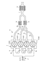
以下、図面を参照しながら、本発明の好ましい実施形態について説明する。図1は、本発明の実施形態による制御装置1、およびこれを適用した内燃機関(以下「エンジン」という)3の概略構成を示している。このエンジン3は、#1〜#4(1番〜4番)気筒Cを有する4気筒のガソリンエンジンであり、車両(図示せず)に搭載されている。
Hereinafter, preferred embodiments of the present invention will be described with reference to the drawings. FIG. 1 shows a schematic configuration of a
このエンジン3では、燃焼サイクルの位相が、#1気筒C→#3気筒C→#4気筒C→#2気筒C→#1気筒Cの順序で180°ずつずれており、気筒Cでの燃焼がこの順序で行われる。
In this
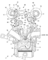
エンジン3のシリンダヘッド3aには、吸気通路4および排気通路5が接続されるとともに、図3に示すように、気筒Cごとに、筒内燃料噴射弁10および点火プラグ11が、燃焼室3bに臨むように取り付けられている。この筒内燃料噴射弁10は、吸気ポート4aの下側に設けられており、燃焼室3b内に燃料を直接、噴射するように構成された直噴タイプのものである。筒内燃料噴射弁10の開弁時間および開弁時期は、後述するECU2によって制御され、それにより、筒内燃料噴射弁10による燃料噴射量および燃料噴射時期が制御される。点火プラグ11の点火時期もまた、ECU2によって制御される。
An
また、エンジン3には、筒内燃料噴射弁10に加え、ポート燃料噴射弁9が気筒Cごとに設けられている。各ポート燃料噴射弁9は、吸気マニホルドの各分岐通路4bに取り付けられ、吸気ポート4aに臨んでいる。このポート燃料噴射弁9の開弁時間および開弁時期もまた、ECU2によって制御され、それにより、ポート燃料噴射弁9による燃料噴射量および燃料噴射時期が制御される。
The
また、このエンジン3では、燃焼モードとして、ポート燃料噴射弁9および筒内燃料噴射弁10から燃料を吸気行程中に噴射することにより生成された均質混合気を、点火プラグ11による火花点火によって燃焼させる火花点火燃焼モード(以下「SI燃焼モード」という)と、後述するように生成された成層混合気を、自己着火によって燃焼させる圧縮着火燃焼モード(以下「CI燃焼モード」という)とを有し、その切替は、ECU2によって制御される。
In this
図1に示すように、排気通路5は、#1〜#4気筒Cにそれぞれ接続された#1〜#4第1排気通路5a〜5dと、#1および#4第1排気通路5a,5dの合流部と#2および#3第1排気通路5b,5cの合流部にそれぞれ接続された第2排気通路6a,6bと、これらの第2排気通路6a,6bの合流部に接続された第3排気通路7で構成されている。
As shown in FIG. 1, the
これらの第2排気通路6a,6bおよび第3排気通路7にはそれぞれ、フィルタ14が設けられている。フィルタ14は、排ガス中の煤などのPMを捕集することによって、大気中に排出されるPMの量を低減する。
A
図3に示すように、気筒Cには、一対の吸気弁12,12および一対の排気弁13,13(ともに1つのみ図示)が設けられている。吸気弁12は、吸気側動弁機構40によって開閉され、排気弁13は、排気側動弁機構60によって開閉される。これらの吸気側動弁機構40および排気側動弁機構60の構成は、本出願人が特願2009−168228号ですでに提案したものと同様であるので、以下、その概略を簡単に説明する。
As shown in FIG. 3, the cylinder C is provided with a pair of
吸気側動弁機構40は、吸気弁12のリフトおよびバルブタイミングを変更する可変機構で構成されている。なお、吸気弁12のリフトおよび後述する排気弁13のリフトはそれぞれ、吸気弁12および排気弁13の最大揚程を表すものとする。
The intake
吸気側動弁機構40は、回転自在の吸気カムシャフト41、吸気カムシャフト41に一体に設けられた一対の吸気カム42,42(1つのみ図示)、吸気コントロールシャフト43、この吸気コントロールシャフト43を駆動するアクチュエータ44(図2参照)、支持軸47に揺動自在に支持された一対の揺動カム45,45(1つのみ図示)、コントロールアーム機構46、および吸気カム位相可変機構50などを備えている。この吸気カム位相可変機構50は、吸気カムシャフト41のクランクシャフト(図示せず)に対する相対的な位相を無段階に変更するものである。
The intake
吸気カムシャフト41は、吸気スプロケットおよびタイミングチェーン(いずれも図示せず)を介して、クランクシャフトに連結されており、クランクシャフトが2回転するごとに1回転する。
The
コントロールアーム機構46は、コントロールアーム46a、ローラ46bおよび吸気ロッカアーム46cなどを備えている。コントロールアーム46aは、基端部において、吸気コントロールシャフト43の偏心軸43aに回動自在に支持されている。コントロールアーム46aの他端部には、ローラ46bが設けられている。コントロールアーム46aは、ローラ46bを介して揺動カム45に当接している。
The
吸気ロッカアーム46cは、吸気コントロールシャフト43に回動自在に支持された本体部46dと、本体部46dから延びる延出部46eなどを備えており、延出部46eにおいて、ローラ46bと吸気弁12に当接している。
The
以上の構成により、揺動カム45が吸気カム42で押圧されていない状態では、吸気弁12は図3に示す閉弁位置に保持される。また、吸気カムシャフト41の回転に伴い、揺動カム45が吸気カム42で押圧されると、揺動カム45は、支持軸47を中心として、図3の反時計方向に回動する。その際、ローラ46bが揺動カム45で押圧されることによって、ローラ46bを介して吸気ロッカアーム46cが吸気コントロールシャフト43を中心として、図3の反時計方向に回動し、吸気弁12を下方に押し下げることによって、吸気弁12が開弁する。
With the above configuration, when the
また、前述したアクチュエータ44を介して吸気コントロールシャフト43を回動させると、コントロールアーム46aが、偏心軸43を中心として図3の左右方向に移動する。この移動に伴い、コントロールアーム46aの揺動カム45への当接位置が変更され、それにより、吸気弁12のリフトおよびバルブタイミングが無段階に変更される。
When the
前述した排気側動弁機構60は、回転自在の排気カムシャフト61、排気カムシャフト61に一体に設けられた一対の排気カム62,62(1つのみ図示)、排気コントロールシャフト63、この排気コントロールシャフト63に回動自在に支持されるとともに、排気弁13,13の上端にそれぞれ当接する一対のロッカアーム64,64(1つのみ図示)、ロッカアーム64に設けられたローラ65、および排気カム位相可変機構70などを備えている。この排気カム位相可変機構70は、排気カムシャフト61のクランクシャフトに対する相対的な位相を無段階に変更するものである。
The exhaust
排気カムシャフト61は、排気スプロケットおよびタイミングチェーンを介して、クランクシャフト(いずれも図示せず)に連結されており、クランクシャフトが2回転するごとに1回転する。排気カムシャフト61が回転すると、ロッカアーム64,64が排気カム62で押圧され、排気コントロールシャフト63を中心として、図3の時計方向に回動することにより、排気弁13,13が開弁する。
The
また、エンジン3は、CI燃焼モードにおいて、排ガスを気筒C内に再度、吸入させるためのEGR吸入機構80を備えている。
Further, the
このEGR吸入機構80は、吸気行程から圧縮行程までの間の所定期間において、排気弁13を開弁することによって、排気通路5の第1排気通路5a〜5dに一旦、排出された排ガスを気筒C内に再吸入するものである。図3および図4に示すように、EGR吸入機構80は、2つの吸気カム42,42の間に設けられ、吸気カムシャフト41と一体のEGRカム81、支持軸47に回動自在に支持されたロッカカム82、コントロールアーム83、レバー84、および切替機構85などを備えている。EGRカム81は、ロッカカム82のローラ82aに当接している。
The
コントロールアーム83は、基端部において、排気コントロールシャフト63の偏心軸63aに回動自在に支持されている。コントロールアーム83の他端部には、ローラ83aが設けられている。コントロールアーム83は、ローラ83aを介してロッカカム82に当接している。
The
レバー84は、2つのロッカアーム64,64の間に設けられている。レバー84は、三角形状を有しており、その頂角部において、排気コントロールシャフト63に回動自在に支持されており、一方の底角部において、コントロールアーム83の押圧部83bに当接している。
The
以上の構成により、吸気カムシャフト41の回転に伴い、ローラ82aがEGRカム81で押圧されると、ロッカカム82は、支持軸47を中心として、図3の時計方向に回動する。その際、コントロールアーム83のローラ83aがロッカカム82で押圧されることによって、コントロールアーム83が排気コントロールシャフト63を中心として、図3の時計方向に回動し、それに伴って、押圧部83bがレバー84を押圧する。これにより、レバー84は、排気コントロールシャフト63を中心として、図3の時計方向に回動する。
With the above configuration, when the
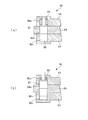
図4に示すように、切替機構85は、ロッカアーム64,64およびレバー84に形成されたシリンダ86a〜86c、シリンダ86a〜86cに収容された連結ピストン87,88などで構成されている。シリンダ86aには、連結ピストン87,88を反対側のシリンダ86c側に付勢する戻しばね89が設けられている。さらに、シリンダ86cには、排気コントロールシャフト63に形成された油路(図示せず)を介して、油圧が供給される。このシリンダ86cへの油圧の供給は、ECU2により、ポンプ(図示せず)から油路への油圧の供給・停止を制御することによって、行われる。
As shown in FIG. 4, the
以上の構成により、シリンダ86cに油圧が供給されていない状態では、戻しばね89の付勢力によって、連結ピストン87がシリンダ86bに収容され、連結ピストン88がシリンダ86cに収容される(図4(a))。これにより、ロッカアーム64とレバー84が互いに遮断され、フリーな状態になることによって、レバー84の動きは、ロッカアーム64には伝達されず、レバー84のみがEGRカム81によって駆動される。
With the above configuration, when no hydraulic pressure is supplied to the
一方、シリンダ86cに油圧が供給されると、この油圧により、連結ピストン87,88が戻しばね89の付勢力に抗してシリンダ86a側に移動することによって、連結ピストン87がシリンダ86aとシリンダ86bにまたがった状態で係合し、連結ピストン88がシリンダ86bとシリンダ86cにまたがった状態で係合する(図4(b))。これにより、レバー84とロッカアーム64が連結され、EGRカム81の動きがレバー84を介してロッカアーム64に伝達されることによって、排気弁13は、一定のリフトおよび一定のバルブタイミングで開閉される。
On the other hand, when the hydraulic pressure is supplied to the
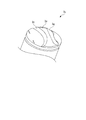
また、シリンダヘッド3aには、複数のガイド壁3dが取り付けられている。図3に示すように、ガイド壁3dは、#1〜#4排気ポート8a〜8dのそれぞれの開口にその周方向の一部にわたって延びるとともに、燃焼室3b内に突出している。各ガイド壁3dは、吸気ポート4a側に配置されており、その長さは#1〜#4排気ポート8a〜8dの開口の半径よりも小さい。また、ガイド壁3dの突出高さは、排気弁13のリフトとほぼ同じであり、例えば2〜3mmに設定されている。
A plurality of
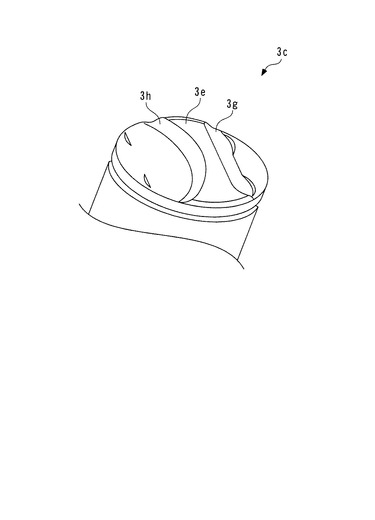
図5に示すように、ピストン3cの頂面には、凸部3eが形成されている。この凸部3eは、その中心が吸気弁12側になるように配置されている。また、凸部3eの吸気弁12側の縁部3gはほぼ直線状に形成されているのに対して、排気弁13側の縁部3hは、吸気弁12側にくぼんだ状態で湾曲している。
As shown in FIG. 5, a
以上の構成により、CI燃焼モードにおいて、EGR吸入機構80により排気弁13が開弁されると、排気通路5に排出された排ガスは、排気弁13を介して気筒C内に再吸入される。このとき、排ガスは、ガイド壁3dによって、排気弁13側の内壁に沿うように下方に案内されながら気筒C内に吸入されるとともに、ピストン3cの凸部3eによって、吸入された排ガスの吸気弁12側への流出が阻止される。その結果、排ガスは、図1に実線Aで示すように気筒C内に流入する。これにより、気筒C内の排気弁13側には、より高温の排ガスによる高温ガス層T1が形成され、吸気弁12側には、より低温の新気による低温ガス層T2が形成されることによって、新気と排ガスが成層化される。
With the above configuration, when the
また、EGR吸入機構80によって排気弁13が開弁する気筒Cに対して燃焼サイクルの位相が360°ずれた、排気行程にある気筒Cから、第1排気通路5a〜5dを介して圧力が導入される。例えば、#1気筒Cと#4気筒Cの位相が互いに360°ずれているため、#1気筒Cが吸気行程から圧縮行程の間にあるときに、#4気筒Cは、膨張行程から排気行程の間にある。このため、#1気筒Cに排ガスを再吸入する場合、#4気筒Cから排出される排ガスの圧力によって、#1気筒Cへの排ガスの再吸入を適切に行わせることができる。
In addition, pressure is introduced through the
また、エンジン3には、クランク角センサ21が設けられている。このクランク角センサ21は、クランクシャフトの回転に伴い、パルス信号であるCKR信号およびTDC信号をECU2に出力する。
The
CRK信号は、所定クランク角(例えば30°)ごとに出力される。ECU2は、このCRK信号に基づき、エンジン3の回転数(以下「エンジン回転数」という)NEを算出する。また、TDC信号は、いずれかの気筒Cにおいてピストン3cが吸気行程の開始時の上死点よりも若干、手前の所定のクランク角位置にあることを表す信号であり、本実施形態のようにエンジン3が4気筒の場合には、クランク角180゜ごとに出力される。
The CRK signal is output every predetermined crank angle (for example, 30 °). The
吸気通路4には、上流側から順に、吸気温センサ22およびエアフローセンサ23が設けられている。吸気温センサ22は、吸気通路4内の温度(以下「吸気温」という)TAを検出し、それを表す検出信号をECU2に出力する。エアフローセンサ23は、エンジン3に吸入される新気量GAIRを検出し、それを表す検出信号をECU2に出力する。
An intake
また、エンジン3の本体には、水温センサ24が設けられている。この水温センサ24は、エンジン3のシリンダブロック3f内を循環する冷却水の温度(以下「エンジン水温」という)TWを検出し、それを表す検出信号をECU2に出力する。
A
ECU2には、アクセル開度センサ25から、車両のアクセルペダル(図示せず)の踏み込み量(以下「アクセル開度」という)APを表す検出信号が出力される。
The
ECU2は、CPU、RAM、ROMおよびI/Oインターフェース(いずれも図示せず)などから成るマイクロコンピュータで構成されている。ECU2は、前述した各種のセンサ21〜25の検出信号などに応じて、エンジン3の運転状態を判別するとともに、判別した運転状態に応じて、エンジン3の燃焼モードを、SI燃焼モードまたはCI燃焼モードに決定する。また、ECU2は、決定した燃焼モードに応じて、燃焼制御処理や吸気弁12の閉弁制御処理などの各種の制御処理を実行する。なお、本実施形態では、ECU2が、負荷検出手段および閉弁タイミング設定手段に相当する。
The
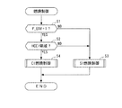
図6は、上述した燃焼制御処理を示すフローチャートである。本処理は、TDC信号の発生に同期して実行される。本処理では、まずステップ1(「S1」と図示。以下同じ)において、環境条件フラグF_ENVが「1」であるか否かを判別する。この環境条件フラグF_ENVは、自己着火による燃焼に適した温度状態が燃焼室3b内に確保されていると判定されているときに「1」にセットされるものであり、吸気温TAおよびエンジン水温TWがそれぞれの所定温度以上のときに、そのような温度状態が確保されていると判定される。
FIG. 6 is a flowchart showing the combustion control process described above. This process is executed in synchronization with the generation of the TDC signal. In this process, first, in step 1 (illustrated as “S1”, the same applies hereinafter), it is determined whether or not the environmental condition flag F_ENV is “1”. This environmental condition flag F_ENV is set to “1” when it is determined that a temperature state suitable for combustion by self-ignition is secured in the
このステップ1の判別結果がNOのときには、自己着火に適した燃焼室3b内の温度状態が確保されていないとして、燃焼モードをSI燃焼モードに決定し、SI燃焼制御を実行した(ステップ3)後、本処理を終了する。
When the determination result in
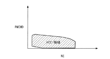
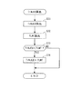
一方、ステップ1の判別結果がYESのときには、エンジン3がCI燃焼を実行すべき運転領域(以下「HCCI領域」という)にあるか否かを判別する(ステップ2)。この判別は、図7に示すマップに基づき、エンジン回転数NEおよび要求トルクPMCMDに応じて行われる。このマップでは、HCCI領域は、エンジン回転数NEが低〜中回転域にあり、かつ要求トルクPMCMDが低〜中負荷域にある運転領域に設定されている。
On the other hand, when the determination result in
このステップ2の判別結果がNOで、エンジン3がHCCI領域にないときには、燃焼モードをSI燃焼モードに決定し、前記ステップ3でSI燃焼制御を実行した後、本処理を終了する。
If the determination result in
このSI燃焼制御は、以下のようにして行われる。まず、エンジン回転数NEおよび要求トルクPMCMDに応じ、所定のマップ(図示せず)を検索することによって、燃料噴射量QINJを算出する。次に、エンジン回転数NEが所定値以下で、かつ要求トルクPMCMDが所定値以下のときには、燃料噴射量QINJの燃料を筒内燃料噴射弁10から気筒Cに噴射する。一方、それ以外のときには、燃料噴射量QINJに対して所定割合(例えば80%)の燃料をポート燃料噴射弁9から吸気ポート4aに噴射し、残りの割合の燃料を筒内燃料噴射弁10から気筒Cに噴射する。なお、要求トルクPMCMDは、エンジン回転数NEおよびアクセル開度APに応じ、所定のマップ(図示せず)を検索することによって算出される。
This SI combustion control is performed as follows. First, the fuel injection amount QINJ is calculated by searching a predetermined map (not shown) according to the engine speed NE and the required torque PMCMD. Next, when the engine speed NE is equal to or lower than a predetermined value and the required torque PMCMD is equal to or lower than the predetermined value, fuel of the fuel injection amount QINJ is injected from the in-cylinder
一方、ステップ2の判別結果がYESで、エンジン3がHCCI領域にあるときには、燃焼モードをCI燃焼モードに決定し、CI燃焼制御を実行した(ステップ4)後、本処理を終了する。
On the other hand, if the determination result in
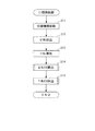
図8は、このCI燃焼制御処理のサブルーチンを示している。本処理では、まずステップ11において、切替機構85を駆動し、レバー84とロッカアーム64を連結することによって、吸気行程において排気弁13を開弁可能な状態にする。
FIG. 8 shows a subroutine of this CI combustion control process. In this process, first, in
次に、エンジン回転数NEおよび要求トルクPMCMDに応じ、それぞれの所定のマップ(図示せず)を検索することによって、吸気行程中に噴射する燃料噴射量QINJおよび燃料噴射時期TINJをそれぞれ算出する(ステップ12,13)。この燃料噴射時期TINJは、クランク角CAで表される。上記のようにして算出された燃料噴射量QINJは、前述したSI燃焼モードにおける、低回転・低負荷以外の運転状態の場合と同様、ポート燃料噴射弁9および筒内燃料噴射弁10から所定割合に分けて噴射される。
Next, by searching respective predetermined maps (not shown) according to the engine speed NE and the required torque PMCMD, the fuel injection amount QINJ and the fuel injection timing TINJ to be injected during the intake stroke are respectively calculated (
次いで、排気燃料噴射量QINJEXを算出する(ステップ14)。この排気燃料噴射量QINJEXは、排気行程中に噴射する燃料量であり、その算出処理については後述する。次に、排気噴射時期TINJEXを算出し(ステップ15)、本処理を終了する。この排気噴射時期TINJEXもまた、クランク角CAで表され、その算出処理については後述する。 Next, an exhaust fuel injection amount QINJEX is calculated (step 14). The exhaust fuel injection amount QINJEX is a fuel amount injected during the exhaust stroke, and the calculation process will be described later. Next, the exhaust injection timing TINJEX is calculated (step 15), and this process is terminated. The exhaust injection timing TINJEX is also represented by a crank angle CA, and the calculation process will be described later.
図9は、排気燃料噴射量QINJEXの算出処理のサブルーチンを示している。本処理ではまず、ステップ21において、次式(1)に従って、再吸入EGR量GEを算出する。
![]()
![]()
次に、吸気量GAIR、ステップ12で算出した燃料噴射量QINJ、およびステップ21で算出した再吸入EGR量GEを用い、次式(2)に従って、第1燃料噴射量QEX1を算出する(ステップ22)。
次に、再吸入EGR量GEを用い、次式(3)に従って、第2燃料噴射量QEX2を算出する(ステップ23)。
次に、上記のようにして算出した第1燃料噴射量QEX1が第2燃料噴射量QEX2よりも小さいか否かを判別する(ステップ24)。この判別結果がYESのときには、第1燃料噴射量QEX1を排気燃料噴射量QINJEXとして設定し(ステップ25)、本処理を終了する。 Next, it is determined whether or not the first fuel injection amount QEX1 calculated as described above is smaller than the second fuel injection amount QEX2 (step 24). When the determination result is YES, the first fuel injection amount QEX1 is set as the exhaust fuel injection amount QINJEX (step 25), and this process is terminated.
一方、ステップ24の判別結果がNOで、QEX1≧QEX2のときには、第2燃料噴射量QEX2を排気燃料噴射量QINJEXとして設定し(ステップ26)、本処理を終了する。
On the other hand, if the determination result in
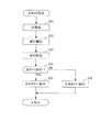
図10は、前述した排気噴射時期TINJEXの算出処理のサブルーチンを示している。本処理ではまず、ステップ31において、前記ステップ21で算出した再吸入EGR量GEに応じ、所定のマップ(図示せず)を検索することによって、排気噴射時期TINJEXを算出する。
FIG. 10 shows a subroutine for calculating the exhaust injection timing TINJEX. In this process, first, in
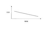
次に、要求トルクPMCMDに応じ、図12に示すマップを検索することによって、排気噴射時期TINJEXの進角側のリミット値TLMTを算出する(ステップ32)。このリミット値TLMTは、燃料の大気中への流出を抑制するために排気噴射時期TINJEXを制限するためのものである。このマップでは、リミット値TLMTは、要求トルクPMCMDが高いほど、再吸入EGR量GEが少なくなるため、燃料の大気中への流出を抑制するために、より大きな値、すなわちより遅角側に設定されている。これにより、排気噴射時期TINJEXは、より遅いタイミングに設定される。 Next, the limit value TLMT on the advance side of the exhaust injection timing TINJEX is calculated by searching the map shown in FIG. 12 according to the required torque PMCMD (step 32). This limit value TLMT is for limiting the exhaust injection timing TINJEX in order to suppress the outflow of fuel into the atmosphere. In this map, the limit value TLMT is set to a larger value, that is, a more retarded side in order to suppress the outflow of fuel into the atmosphere because the re-intake EGR amount GE decreases as the required torque PMCMD increases. Has been. Thereby, the exhaust injection timing TINJEX is set to a later timing.
次いで、上記のようにして算出した排気噴射時期TINJEXがリミット値TLMTよりも小さいか否かを判別する(ステップ33)。この判別結果がNOのときには、そのまま本処理を終了する。 Next, it is determined whether or not the exhaust injection timing TINJEX calculated as described above is smaller than the limit value TLMT (step 33). When this determination result is NO, this process is terminated as it is.
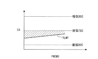
一方、ステップ33の判別結果がYESで、TINJEX<TLMTのときには、リミット値TLMTを排気噴射時期TINJEXとして設定し(ステップ34)、本処理を終了する。以上により、排気噴射時期TINJEXは、リミット値TLMTと排気上死点との間(図11のハッチングで示す領域)に設定され、この領域内で燃料が噴射される。 On the other hand, if the determination result in step 33 is YES and TINJEX <TLMT, the limit value TLMT is set as the exhaust injection timing TINJEX (step 34), and this process is terminated. Thus, the exhaust injection timing TINJEX is set between the limit value TLMT and the exhaust top dead center (a region indicated by hatching in FIG. 11), and fuel is injected in this region.
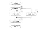
図13は、前述した吸気弁12の閉弁制御処理を示すフローチャートである。本処理もまた、TDC信号の発生に同期して実行される。本処理では、まずステップ41において、燃焼モードがCI燃焼モードであるか否かを判別する。この判別結果がNOで、燃焼モードがSI燃焼モードのときには、要求トルクPMCMDに応じ、所定のマップ(図示せず)からマップ値TSIを検出し、このマップ値TSIを閉弁タイミングTIMCとして設定する(ステップ42)。
FIG. 13 is a flowchart showing the valve closing control process of the
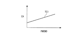
一方、前記ステップ41の判別結果がYESで、CI燃焼モードのときには、要求トルクPMCMDに応じ、図14に示すマップからマップ値TCIを検出し、このマップ値TCIを閉弁タイミングTIMCとして設定する(ステップ43)。このマップでは、マップ値TIMCは、クランク角CAで表されており、要求トルクPMCMDが高いほど、より大きな値に設定されている。
On the other hand, if the determination result in
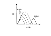
ステップ42または43に続くステップ44では、設定された閉弁タイミングTIMCに基づいてアクチュエータ44を駆動した後、本処理を終了する。このような制御により、CI燃焼モード時には、吸気弁12の閉弁タイミングTIMCは、要求トルクPMCMDが低いほど、より早いタイミングに設定される(図15参照)。また、EGR吸入機構80による排気弁13のバルブタイミングは一定に設定されており、要求トルクPMCMDが所定値REFのときには、吸気弁12と排気弁13のバルブオーバーラップの期間が値0になる(同図の破線)。
In
さらに、要求トルクPMCMDが所定値REFよりも小さいときには、排気弁13が開弁する前に吸気弁12が閉弁する負のオーバーラップが発生し、その期間は、要求トルクPMCMDが低いほど、より長くなる(同図の実線)。また、要求トルクPMCMDが所定値REFよりも大きいときには、排気弁13が開弁した後に吸気弁12が閉弁する正のオーバーラップが発生し、その期間は、要求トルクPMCMDが高いほど、より長くなる(同図の2点鎖線)。
Further, when the required torque PMCMD is smaller than the predetermined value REF, a negative overlap occurs in which the
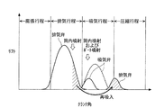
次に、図16を参照しながら、CI燃焼モードにおいて得られる動作をとりまとめて説明する。まず、排気行程において、排気側動弁機構60によって排気弁13が開弁され、排ガスが排気通路5に排出される。また、この排気行程中に、筒内燃料噴射弁10から気筒C内に燃料が噴射される。この燃料は、排ガスとともに排気通路5に排出される。そして、排出された燃料が、排気通路5において、排ガスの熱によって十分に暖められ、蒸発し、排ガスに混合されることによって、高温ガスが生成される。
Next, the operations obtained in the CI combustion mode will be collectively described with reference to FIG. First, in the exhaust stroke, the
その後の吸気行程において、吸気側動弁機構40によって吸気弁12が開弁され、新気が気筒C内に吸入される。また、この吸気行程中に、ポート燃料噴射弁9および筒内燃料噴射弁10から気筒C内に燃料が供給され、この燃料が新気と混合されることによって、低温ガスが生成される。
In the subsequent intake stroke, the
また、吸気行程の終期にEGR吸入機構80によって排気弁13が開弁されることによって、排気通路5において生成された高温ガスが気筒C内に再吸入される(同図のハッチング)。以上のようにして生成された低温ガスおよび高温ガスは、ガイド壁3dおよび凸部3eによって、気筒C内で高温ガス層T1と低温ガス層T2に成層化される。高温ガス層T1は排気弁13側に分布し、低温ガス層T2は吸気弁12側に分布する。また、その後の圧縮行程において、高温ガス層T1および低温ガス層T2が自己着火により燃焼する。この燃焼は、より高温の高温ガス層T1から開始され、低温ガス層T2に至る。
Further, when the
前述したように、要求トルクPMCMDが所定値REFよりも小さいときには、排気弁13が開弁する前に吸気弁12を閉弁する(同図の実線)。このような吸気弁12と排気弁13との負のオーバーラップにより、ピストン3cの下降に伴って気筒C内に大きな負圧が発生する。その後、排気弁13を開弁することによって、発生した負圧によって排ガスを気筒C内に吸入する。したがって、そのような大きな負圧を用いて、大きな流速の排ガスを気筒内に再吸入することができる。これにより、自己着火による燃焼を安定して行うことができる。
As described above, when the required torque PMCMD is smaller than the predetermined value REF, the
また、要求トルクPMCMDが低いほど、閉弁タイミングTIMCをより早いタイミングに設定することによって、負のオーバーラップの期間をより長く確保することができる。その結果、エンジン3の負荷が低く、気筒C内の温度が低下しやすい場合においても、気筒C内の温度を確実に上昇させることができ、自己着火による燃焼を安定して行うことができる。
Further, the lower the required torque PMCMD, the longer the negative overlap period can be secured by setting the valve closing timing TIMC to an earlier timing. As a result, even when the load on the
さらに、要求トルクPMCMDが所定値REFよりも大きいときには、排気弁13が開弁した後に吸気弁12を閉弁することによって(同図の破線)、気筒C内に発生する負圧を小さくすることができる。これにより、再吸入される排ガスの量を抑制することによって、気筒C内の温度の過度の上昇を回避でき、エンジン3の負荷が高い場合においても、自己着火による燃焼を安定して行うことができる。
Further, when the required torque PMCMD is larger than the predetermined value REF, the negative pressure generated in the cylinder C is reduced by closing the
なお、本発明は、説明した実施形態に限定されることなく、種々の態様で実施することができる。例えば、実施形態では、エンジン3の負荷を表すパラメータとして、要求トルクPMCMDを用いているが、これに代えて、エンジンの負荷を表す他のパラメータを用いてもよい。また、実施形態では、EGR吸入機構80は、排気弁13のバルブタイミングを変更不能に構成されているが、変更可能に構成してもよい。
In addition, this invention can be implemented in various aspects, without being limited to the described embodiment. For example, in the embodiment, the required torque PMCMD is used as a parameter representing the load of the
さらに、実施形態は、本発明を車両に搭載されたガソリンエンジンに適用した例であるが、本発明は、これに限らず、ガソリンエンジン以外のディーゼルエンジンなどの各種のエンジンに適用してもよく、また、車両用以外のエンジン、例えば、クランク軸を鉛直に配置した船外機などのような船舶推進機用エンジンにも適用可能である。その他、本発明の趣旨の範囲内で、細部の構成を適宜、変更することが可能である。 Further, the embodiment is an example in which the present invention is applied to a gasoline engine mounted on a vehicle, but the present invention is not limited to this, and may be applied to various engines such as a diesel engine other than a gasoline engine. Also, the present invention can be applied to engines other than those for vehicles, for example, engines for marine propulsion devices such as outboard motors having a crankshaft arranged vertically. In addition, it is possible to appropriately change the detailed configuration within the scope of the gist of the present invention.
1 制御装置
2 ECU(負荷検出手段および閉弁タイミング設定手段)
3 エンジン
3c ピストン
5 排気通路
12 吸気弁
13 排気弁
21 クランク角センサ(負荷検出手段)
25 アクセル開度センサ(負荷検出手段)
40 吸気側動弁機構
80 EGR吸入機構(排ガス吸入機構)
C 気筒
TIMC 閉弁タイミング
PMCMD 要求トルク(内燃機関の負荷)
1
3
25 Accelerator opening sensor (load detection means)
40 Intake
C cylinder TIMMC valve closing timing PMCMD Required torque (load of internal combustion engine)
Claims (6)
ピストンが下降する吸気行程中に吸気弁を開閉するとともに、当該吸気弁の閉弁タイミングを変更可能に構成された吸気側動弁機構と、
前記吸気行程から圧縮行程までの間の所定期間において排気弁を開弁することによって、排気通路に排出された排ガスを気筒内に再度、吸入するための排ガス吸入機構と、を備え、
当該排ガス吸入機構は、前記吸気弁が前記吸気行程中の開弁後に閉弁している状態で前記排気弁を閉弁状態に維持する負のオーバーラップを生じさせることによって、前記ピストンの下降に伴って負圧を発生させるとともに、その後、前記排気弁を前記所定期間に開弁することによって、前記発生した負圧によって排ガスを前記気筒内に吸入し、
前記内燃機関の負荷を検出する負荷検出手段と、
当該検出された内燃機関の負荷が低いほど、前記負のオーバーラップをより長くし、より大きな前記負圧を発生させるために、前記吸気弁の閉弁タイミングをより早いタイミングに設定する閉弁タイミング設定手段と、をさらに備えることを特徴とする内燃機関の制御装置。 A control device for an internal combustion engine that has a compression ignition combustion mode as a combustion mode and controls the internal combustion engine in the compression ignition combustion mode,
An intake side valve mechanism configured to open and close the intake valve during the intake stroke in which the piston descends and to change the closing timing of the intake valve;
An exhaust gas intake mechanism for re-inhaling the exhaust gas discharged into the exhaust passage into the cylinder by opening the exhaust valve in a predetermined period between the intake stroke and the compression stroke;
The exhaust gas intake mechanism causes the piston to descend by generating a negative overlap that keeps the exhaust valve closed while the intake valve is closed after opening during the intake stroke. Along with this, a negative pressure is generated, and thereafter, the exhaust valve is opened during the predetermined period, whereby exhaust gas is sucked into the cylinder by the generated negative pressure ,
Load detecting means for detecting a load of the internal combustion engine;
As the detected load of the internal combustion engine is lower, in order to make the negative overlap longer and generate a larger negative pressure, the closing timing of the intake valve is set to an earlier timing control apparatus for an internal combustion engine, characterized by further comprising a setting means.
ピストンが下降する吸気行程中に吸気弁を開閉し、Open and close the intake valve during the intake stroke when the piston descends,
前記吸気弁が前記吸気行程中の開弁後に閉弁している状態で前記排気弁を閉弁状態に維持する負のオーバーラップを生じさせることによって、前記ピストンの下降に伴って負圧を発生させ、その後、前記排気弁を前記吸気行程から圧縮行程までの間の所定期間において開弁することによって、前記発生した負圧によって排ガスを前記気筒内に吸入し、Generates negative pressure as the piston descends by creating a negative overlap that keeps the exhaust valve closed while the intake valve is closed after opening during the intake stroke Then, by opening the exhaust valve in a predetermined period between the intake stroke and the compression stroke, exhaust gas is sucked into the cylinder by the generated negative pressure,
前記内燃機関の負荷を検出し、Detecting the load of the internal combustion engine;
当該検出された内燃機関の負荷が低いほど、前記負のオーバーラップをより長くし、より大きな前記負圧を発生させるために、前記吸気弁をより早いタイミングで閉弁することを特徴とする内燃機関の制御方法。The intake valve is closed at an earlier timing in order to make the negative overlap longer and to generate a larger negative pressure as the detected load of the internal combustion engine is lower How to control the engine.
Priority Applications (1)
| Application Number | Priority Date | Filing Date | Title |
|---|---|---|---|
| JP2010021026A JP5073765B2 (en) | 2010-02-02 | 2010-02-02 | Control device and control method for internal combustion engine |
Applications Claiming Priority (1)
| Application Number | Priority Date | Filing Date | Title |
|---|---|---|---|
| JP2010021026A JP5073765B2 (en) | 2010-02-02 | 2010-02-02 | Control device and control method for internal combustion engine |
Publications (2)
| Publication Number | Publication Date |
|---|---|
| JP2011157888A JP2011157888A (en) | 2011-08-18 |
| JP5073765B2 true JP5073765B2 (en) | 2012-11-14 |
Family
ID=44590048
Family Applications (1)
| Application Number | Title | Priority Date | Filing Date |
|---|---|---|---|
| JP2010021026A Expired - Fee Related JP5073765B2 (en) | 2010-02-02 | 2010-02-02 | Control device and control method for internal combustion engine |
Country Status (1)
| Country | Link |
|---|---|
| JP (1) | JP5073765B2 (en) |
Families Citing this family (3)
| Publication number | Priority date | Publication date | Assignee | Title |
|---|---|---|---|---|
| DE102012001316B4 (en) * | 2012-01-25 | 2023-10-26 | Mercedes-Benz Group AG | Internal combustion engine valve train device |
| JP6131840B2 (en) * | 2013-11-18 | 2017-05-24 | マツダ株式会社 | Control device for compression ignition engine |
| JP6213175B2 (en) * | 2013-11-18 | 2017-10-18 | マツダ株式会社 | Control device for compression ignition engine |
Family Cites Families (3)
| Publication number | Priority date | Publication date | Assignee | Title |
|---|---|---|---|---|
| JP4098684B2 (en) * | 2003-08-13 | 2008-06-11 | 本田技研工業株式会社 | Control device for compression ignition internal combustion engine |
| JP2007064021A (en) * | 2005-08-29 | 2007-03-15 | Mazda Motor Corp | Spark ignition type 4-cycle engine |
| JP4639166B2 (en) * | 2006-05-18 | 2011-02-23 | 本田技研工業株式会社 | Control device |
-
2010
- 2010-02-02 JP JP2010021026A patent/JP5073765B2/en not_active Expired - Fee Related
Also Published As
| Publication number | Publication date |
|---|---|
| JP2011157888A (en) | 2011-08-18 |
Similar Documents
| Publication | Publication Date | Title |
|---|---|---|
| CN101568708B (en) | Engine warm-up for homogeneous charge compression ignition engines | |
| JP5786679B2 (en) | Start control device for compression self-ignition engine | |
| JP3894089B2 (en) | Control device for spark ignition engine | |
| CN101675232B (en) | Engine warm-up for homogeneous charge compression ignition engines | |
| JP5919697B2 (en) | Diesel engine start control device | |
| CN101278113B (en) | Control device and method for internal combustion engine | |
| CN105189989B (en) | The start-control device of pre-mixing pression ingiter formula engine | |
| JP2011241756A (en) | Apparatus for control of internal combustion engine | |
| JP4468462B2 (en) | Internal EGR control device for internal combustion engine | |
| JP6245114B2 (en) | Control device for compression ignition engine | |
| JP4918910B2 (en) | Internal combustion engine | |
| JP5073765B2 (en) | Control device and control method for internal combustion engine | |
| JP2003097329A (en) | Compression ignition type internal combustion engine | |
| JP4983747B2 (en) | Internal combustion engine | |
| JP4419800B2 (en) | Engine starter | |
| JP2009203818A (en) | Control method of internal combustion engine and internal combustion engine system | |
| JP4518251B2 (en) | Control device for internal combustion engine | |
| JP2010048108A (en) | Internal combustion engine | |
| JP5045600B2 (en) | Internal combustion engine | |
| JP4877857B2 (en) | Control device for internal combustion engine | |
| US11131258B2 (en) | Methods and system for reducing engine hydrocarbon emissions | |
| JP5485010B2 (en) | Control device for internal combustion engine | |
| JP5879965B2 (en) | Start control device for compression self-ignition engine | |
| JP2009127485A (en) | Internal combustion engine | |
| JP5948815B2 (en) | Start control device for compression self-ignition engine |
Legal Events
| Date | Code | Title | Description |
|---|---|---|---|
| A521 | Written amendment |
Free format text: JAPANESE INTERMEDIATE CODE: A523 Effective date: 20111027 |
|
| A131 | Notification of reasons for refusal |
Free format text: JAPANESE INTERMEDIATE CODE: A131 Effective date: 20120117 |
|
| A977 | Report on retrieval |
Free format text: JAPANESE INTERMEDIATE CODE: A971007 Effective date: 20120119 |
|
| A521 | Written amendment |
Free format text: JAPANESE INTERMEDIATE CODE: A523 Effective date: 20120220 |
|
| A02 | Decision of refusal |
Free format text: JAPANESE INTERMEDIATE CODE: A02 Effective date: 20120313 |
|
| A521 | Written amendment |
Free format text: JAPANESE INTERMEDIATE CODE: A523 Effective date: 20120514 |
|
| A521 | Written amendment |
Free format text: JAPANESE INTERMEDIATE CODE: A821 Effective date: 20120514 |
|
| A911 | Transfer of reconsideration by examiner before appeal (zenchi) |
Free format text: JAPANESE INTERMEDIATE CODE: A911 Effective date: 20120614 |
|
| TRDD | Decision of grant or rejection written | ||
| A01 | Written decision to grant a patent or to grant a registration (utility model) |
Free format text: JAPANESE INTERMEDIATE CODE: A01 Effective date: 20120724 |
|
| A01 | Written decision to grant a patent or to grant a registration (utility model) |
Free format text: JAPANESE INTERMEDIATE CODE: A01 |
|
| A61 | First payment of annual fees (during grant procedure) |
Free format text: JAPANESE INTERMEDIATE CODE: A61 Effective date: 20120822 |
|
| R150 | Certificate of patent or registration of utility model |
Free format text: JAPANESE INTERMEDIATE CODE: R150 |
|
| FPAY | Renewal fee payment (event date is renewal date of database) |
Free format text: PAYMENT UNTIL: 20150831 Year of fee payment: 3 |
|
| LAPS | Cancellation because of no payment of annual fees |