JP5073737B2 - Fuel cell power generation system - Google Patents

Fuel cell power generation system Download PDF

Info

Publication number
JP5073737B2
JP5073737B2 JP2009505197A JP2009505197A JP5073737B2 JP 5073737 B2 JP5073737 B2 JP 5073737B2 JP 2009505197 A JP2009505197 A JP 2009505197A JP 2009505197 A JP2009505197 A JP 2009505197A JP 5073737 B2 JP5073737 B2 JP 5073737B2
Authority
JP
Japan
Prior art keywords
fuel cell
hydrogen
power generation
generation system
flow path
Prior art date
Legal status (The legal status is an assumption and is not a legal conclusion. Google has not performed a legal analysis and makes no representation as to the accuracy of the status listed.)
Expired - Fee Related
Application number
JP2009505197A
Other languages
Japanese (ja)
Other versions
JPWO2008114722A1 (en
Inventor
博志 柏野
規寿 吉本
公平 鵜川
昭二 西原
Current Assignee (The listed assignees may be inaccurate. Google has not performed a legal analysis and makes no representation or warranty as to the accuracy of the list.)
Hitachi Maxell Energy Ltd
Original Assignee
Hitachi Maxell Energy Ltd
Priority date (The priority date is an assumption and is not a legal conclusion. Google has not performed a legal analysis and makes no representation as to the accuracy of the date listed.)
Filing date
Publication date
Application filed by Hitachi Maxell Energy Ltd filed Critical Hitachi Maxell Energy Ltd
Priority to JP2009505197A priority Critical patent/JP5073737B2/en
Publication of JPWO2008114722A1 publication Critical patent/JPWO2008114722A1/en
Application granted granted Critical
Publication of JP5073737B2 publication Critical patent/JP5073737B2/en
Expired - Fee Related legal-status Critical Current
Anticipated expiration legal-status Critical

Links

Images

Classifications

    • HELECTRICITY
    • H01ELECTRIC ELEMENTS
    • H01MPROCESSES OR MEANS, e.g. BATTERIES, FOR THE DIRECT CONVERSION OF CHEMICAL ENERGY INTO ELECTRICAL ENERGY
    • H01M8/00Fuel cells; Manufacture thereof
    • H01M8/04Auxiliary arrangements, e.g. for control of pressure or for circulation of fluids
    • H01M8/04223Auxiliary arrangements, e.g. for control of pressure or for circulation of fluids during start-up or shut-down; Depolarisation or activation, e.g. purging; Means for short-circuiting defective fuel cells
    • H01M8/04238Depolarisation
    • HELECTRICITY
    • H01ELECTRIC ELEMENTS
    • H01MPROCESSES OR MEANS, e.g. BATTERIES, FOR THE DIRECT CONVERSION OF CHEMICAL ENERGY INTO ELECTRICAL ENERGY
    • H01M8/00Fuel cells; Manufacture thereof
    • H01M8/04Auxiliary arrangements, e.g. for control of pressure or for circulation of fluids
    • H01M8/04223Auxiliary arrangements, e.g. for control of pressure or for circulation of fluids during start-up or shut-down; Depolarisation or activation, e.g. purging; Means for short-circuiting defective fuel cells
    • H01M8/04225Auxiliary arrangements, e.g. for control of pressure or for circulation of fluids during start-up or shut-down; Depolarisation or activation, e.g. purging; Means for short-circuiting defective fuel cells during start-up
    • HELECTRICITY
    • H01ELECTRIC ELEMENTS
    • H01MPROCESSES OR MEANS, e.g. BATTERIES, FOR THE DIRECT CONVERSION OF CHEMICAL ENERGY INTO ELECTRICAL ENERGY
    • H01M8/00Fuel cells; Manufacture thereof
    • H01M8/06Combination of fuel cells with means for production of reactants or for treatment of residues
    • HELECTRICITY
    • H01ELECTRIC ELEMENTS
    • H01MPROCESSES OR MEANS, e.g. BATTERIES, FOR THE DIRECT CONVERSION OF CHEMICAL ENERGY INTO ELECTRICAL ENERGY
    • H01M2250/00Fuel cells for particular applications; Specific features of fuel cell system
    • H01M2250/30Fuel cells in portable systems, e.g. mobile phone, laptop
    • HELECTRICITY
    • H01ELECTRIC ELEMENTS
    • H01MPROCESSES OR MEANS, e.g. BATTERIES, FOR THE DIRECT CONVERSION OF CHEMICAL ENERGY INTO ELECTRICAL ENERGY
    • H01M8/00Fuel cells; Manufacture thereof
    • H01M8/06Combination of fuel cells with means for production of reactants or for treatment of residues
    • H01M8/0606Combination of fuel cells with means for production of reactants or for treatment of residues with means for production of gaseous reactants
    • H01M8/065Combination of fuel cells with means for production of reactants or for treatment of residues with means for production of gaseous reactants by dissolution of metals or alloys; by dehydriding metallic substances
    • YGENERAL TAGGING OF NEW TECHNOLOGICAL DEVELOPMENTS; GENERAL TAGGING OF CROSS-SECTIONAL TECHNOLOGIES SPANNING OVER SEVERAL SECTIONS OF THE IPC; TECHNICAL SUBJECTS COVERED BY FORMER USPC CROSS-REFERENCE ART COLLECTIONS [XRACs] AND DIGESTS
    • Y02TECHNOLOGIES OR APPLICATIONS FOR MITIGATION OR ADAPTATION AGAINST CLIMATE CHANGE
    • Y02BCLIMATE CHANGE MITIGATION TECHNOLOGIES RELATED TO BUILDINGS, e.g. HOUSING, HOUSE APPLIANCES OR RELATED END-USER APPLICATIONS
    • Y02B90/00Enabling technologies or technologies with a potential or indirect contribution to GHG emissions mitigation
    • Y02B90/10Applications of fuel cells in buildings
    • YGENERAL TAGGING OF NEW TECHNOLOGICAL DEVELOPMENTS; GENERAL TAGGING OF CROSS-SECTIONAL TECHNOLOGIES SPANNING OVER SEVERAL SECTIONS OF THE IPC; TECHNICAL SUBJECTS COVERED BY FORMER USPC CROSS-REFERENCE ART COLLECTIONS [XRACs] AND DIGESTS
    • Y02TECHNOLOGIES OR APPLICATIONS FOR MITIGATION OR ADAPTATION AGAINST CLIMATE CHANGE
    • Y02EREDUCTION OF GREENHOUSE GAS [GHG] EMISSIONS, RELATED TO ENERGY GENERATION, TRANSMISSION OR DISTRIBUTION
    • Y02E60/00Enabling technologies; Technologies with a potential or indirect contribution to GHG emissions mitigation
    • Y02E60/30Hydrogen technology
    • Y02E60/50Fuel cells

Description

本発明は、長寿命の燃料電池発電システムに関するものである。   The present invention relates to a long-life fuel cell power generation system.

近年、パソコン、携帯電話などのコードレス機器の普及に伴い、その電源である電池には、ますます小型化、高容量化が要望されている。現在、リチウムイオン二次電池は、エネルギー密度が高く、小型軽量化を図り得る電池として実用化されており、ポータブル電源としての需要が増大している。しかし、このリチウムイオン二次電池は、一部のコードレス機器に対して、十分な連続使用時間を保証することができないという問題がある。   In recent years, with the widespread use of cordless devices such as personal computers and mobile phones, batteries that are power sources are increasingly required to be smaller and have higher capacities. Currently, lithium ion secondary batteries have been put into practical use as batteries that have high energy density and can be reduced in size and weight, and demand for portable power sources is increasing. However, this lithium ion secondary battery has a problem that it cannot guarantee a sufficient continuous use time for some cordless devices.

上記問題の解決に向けて、例えば固体高分子型燃料電池(PEFC)などの燃料電池の開発が進められている。燃料電池は、燃料および酸素の供給を行えば連続的に使用することが可能である。そして、正極と、負極と、電解質としての固体高分子電解質とからなる膜・電極接合体(MEA)を備え、正極活物質に空気中の酸素、負極活物質に水素を用いるPEFCは、リチウムイオン二次電池よりもエネルギー密度が高い電池として注目されている。   In order to solve the above problems, for example, development of fuel cells such as polymer electrolyte fuel cells (PEFC) is underway. The fuel cell can be used continuously if fuel and oxygen are supplied. A PEFC comprising a membrane / electrode assembly (MEA) comprising a positive electrode, a negative electrode, and a solid polymer electrolyte as an electrolyte, using oxygen in the air as the positive electrode active material and hydrogen as the negative electrode active material is lithium ion It is attracting attention as a battery having a higher energy density than a secondary battery.

しかし、現在の燃料電池では、運転を停止しても、燃料電池内に残留する水素により、正極および負極の触媒粒子の成長や、触媒粒子を担持させる炭素粉末の酸化などが生じる。これにより、長期間の使用で正極および負極が劣化するという問題を生じるため、電極の長寿命化が課題とされている。上記正極および負極の劣化のメカニズムは明確ではないが、電池内に残留する水素により、各MEAの開回路電圧が1V近くに達するため、正極では触媒の粒子成長や炭素粉末の酸化が起こり、一方、負極では水素と漏れ込む酸素との燃焼反応などが生じて、正極と同様に触媒の粒子成長や炭素粉末の酸化が起こるのではないかと推測される。   However, in the current fuel cell, even if the operation is stopped, the hydrogen remaining in the fuel cell causes the growth of the positive and negative electrode catalyst particles, the oxidation of the carbon powder supporting the catalyst particles, and the like. As a result, there arises a problem that the positive electrode and the negative electrode deteriorate due to long-term use. The mechanism of the deterioration of the positive electrode and the negative electrode is not clear, but the hydrogen remaining in the battery causes the open circuit voltage of each MEA to reach close to 1 V, so that catalyst particle growth and carbon powder oxidation occur at the positive electrode. In the negative electrode, it is presumed that a combustion reaction between hydrogen and leaking oxygen occurs, and that catalyst particle growth and carbon powder oxidation occur as in the positive electrode.

上記のような燃料電池内に残留する水素に起因する正極および負極の劣化を防止する方法も検討されている。例えば、特許文献1および特許文献2には、水素を燃料とする燃料電池発電システムにおいて、システム停止後に、残留水素を消費するために、燃料電池の有する各MEAに外部抵抗を接続し、残留水素による放電を行う方法が提案されている。   A method for preventing the deterioration of the positive electrode and the negative electrode due to hydrogen remaining in the fuel cell as described above has also been studied. For example, in Patent Document 1 and Patent Document 2, in a fuel cell power generation system using hydrogen as a fuel, an external resistor is connected to each MEA of the fuel cell in order to consume residual hydrogen after the system is stopped. There has been proposed a method of discharging by the above.

更に、特許文献3には、出力用燃料電池とは別に、出力用燃料電池から外部に排出される残留水素を消費するための処理用燃料電池を、ガス排出口に配置する方法が提案されている。   Further, Patent Document 3 proposes a method of disposing a processing fuel cell for consuming residual hydrogen discharged from the output fuel cell to the outside, separately from the output fuel cell, at the gas discharge port. Yes.

特開平11−26003号公報Japanese Patent Laid-Open No. 11-26003 特開2003−115305号公報JP 2003-115305 A 特開2007−80721号公報JP 2007-80721 A WO2006/073113号パンフレットWO2006 / 073113 Pamphlet

しかしながら、特許文献1〜特許文献3に開示された技術は、燃料電池内に余剰の水素が流入することを防ぐものではない。このため、例えば、特許文献4に記載されたように、水素発生物質と水との化学反応を利用して水素を供給する場合には、燃料電池の作動停止、すなわち、燃料電池から外部負荷への電力供給の停止と同時に、水素供給源からの水素供給を完全に停止することは難しいため、余剰水素の消費のために長時間MEAを作動させる必要が生じる。このような場合には、発電を続けることによる電極の劣化が徐々に進行することになる。また、燃料電池の中で、水素ガスの流れの上流側にあるMEA、すなわち、水素ガスの供給源により近いMEAは、水素ガスの下流側、あるいは、水素ガス排出口により近いMEAに比べ、より多くの水素ガスにさらされるため、劣化を生じやすい。特に、特許文献4に記載されたような水素供給源を用いる場合には、多くの余剰水素が燃料電池に流入する可能性があり、各MEAの間で特性のばらつきが生じるのを防ぐため、余剰水素の燃料電池への流入を抑制する必要性が高くなる。   However, the techniques disclosed in Patent Documents 1 to 3 do not prevent surplus hydrogen from flowing into the fuel cell. For this reason, for example, as described in Patent Document 4, when hydrogen is supplied using a chemical reaction between a hydrogen generating substance and water, the operation of the fuel cell is stopped, that is, from the fuel cell to an external load. Since it is difficult to completely stop the hydrogen supply from the hydrogen supply source at the same time as stopping the power supply, it is necessary to operate the MEA for a long time in order to consume surplus hydrogen. In such a case, the deterioration of the electrode due to the continued power generation gradually proceeds. Also, in the fuel cell, the MEA on the upstream side of the hydrogen gas flow, that is, the MEA closer to the hydrogen gas supply source, is more inferior to the downstream side of the hydrogen gas or the MEA closer to the hydrogen gas outlet. Because it is exposed to a lot of hydrogen gas, it tends to deteriorate. In particular, when a hydrogen supply source as described in Patent Document 4 is used, a large amount of surplus hydrogen may flow into the fuel cell, and in order to prevent variation in characteristics among the MEAs, The necessity to suppress the inflow of surplus hydrogen into the fuel cell is increased.

本発明は、酸素を還元する正極と、水素を酸化する負極と、前記正極と前記負極との間に配置された固体電解質膜とを含む第1の膜・電極接合体を含む燃料電池と、前記燃料電池に水素を供給する燃料流路とを含む燃料電池発電システムであって、前記燃料電池は、前記第1の膜・電極接合体を複数含み、前記燃料流路に、前記システムの内部に存在する水素の少なくとも一部を除去することが可能な水素除去装置が接続されており、前記水素除去装置は、酸素を還元する正極と、水素を酸化する負極と、該正極と該負極との間に配置された固体電解質膜とを含む第2の膜・電極接合体を含むことを特徴とする。
The present invention provides a fuel cell including a first membrane-electrode assembly including a positive electrode that reduces oxygen, a negative electrode that oxidizes hydrogen, and a solid electrolyte membrane disposed between the positive electrode and the negative electrode; A fuel cell power generation system including a fuel flow path for supplying hydrogen to the fuel cell, wherein the fuel cell includes a plurality of the first membrane-electrode assemblies, and the fuel flow path includes an interior of the system. Is connected to a hydrogen removing device capable of removing at least part of the hydrogen present in the gas, the hydrogen removing device comprising: a positive electrode for reducing oxygen; a negative electrode for oxidizing hydrogen; the positive electrode and the negative electrode; And a second membrane / electrode assembly including a solid electrolyte membrane disposed between the two .

本発明によれば、燃料電池の作動停止後に水素供給源から燃料電池内に流入する余剰水素を低減することができる。これにより、余剰水素による燃料電池の劣化を抑制し、燃料電池の長寿命化を図ることができる。   According to the present invention, surplus hydrogen flowing into the fuel cell from the hydrogen supply source after the operation of the fuel cell is stopped can be reduced. Thereby, deterioration of the fuel cell due to excess hydrogen can be suppressed, and the life of the fuel cell can be extended.

図1は、本発明の実施態様1の燃料電池発電システムの構成例を示す概略図である。FIG. 1 is a schematic diagram showing a configuration example of a fuel cell power generation system according to Embodiment 1 of the present invention. 図2は、本発明の実施態様1の燃料電池発電システムの別の構成例を示す概略図である。FIG. 2 is a schematic diagram showing another configuration example of the fuel cell power generation system according to Embodiment 1 of the present invention. 図3は、本発明の燃料電池発電システムに係る燃料電池の一例を示す模式断面図である。FIG. 3 is a schematic cross-sectional view showing an example of a fuel cell according to the fuel cell power generation system of the present invention. 図4は、本発明の燃料電池発電システムに係る水素供給源の一例を示す模式図である。FIG. 4 is a schematic diagram showing an example of a hydrogen supply source according to the fuel cell power generation system of the present invention. 図5は、本発明の燃料電池発電システムに係る水素除去装置の一例を示す模式断面図である。FIG. 5 is a schematic cross-sectional view showing an example of a hydrogen removal apparatus according to the fuel cell power generation system of the present invention. 図6は、本発明の実施態様2の燃料電池発電システムの構成例を示す概略図である。FIG. 6 is a schematic diagram showing a configuration example of the fuel cell power generation system according to Embodiment 2 of the present invention. 図7は、本発明の実施態様2の燃料電池発電システムの別の構成例を示す概略図である。FIG. 7 is a schematic diagram showing another configuration example of the fuel cell power generation system according to Embodiment 2 of the present invention. 図8は、本発明の実施態様2の燃料電池発電システムのさらに別の構成例を示す概略図である。FIG. 8 is a schematic diagram showing still another configuration example of the fuel cell power generation system according to Embodiment 2 of the present invention. 図9は、本発明の実施態様2の燃料電池発電システムのさらに別の構成例を示す概略図である。FIG. 9 is a schematic diagram showing still another configuration example of the fuel cell power generation system according to Embodiment 2 of the present invention. 図10は、本発明の実施態様2の燃料電池発電システムのさらに別の構成例を示す概略図である。FIG. 10 is a schematic diagram showing still another configuration example of the fuel cell power generation system according to Embodiment 2 of the present invention. 図11は、本発明の実施態様3の燃料電池発電システムの構成例を示す概略図である。FIG. 11 is a schematic diagram illustrating a configuration example of a fuel cell power generation system according to Embodiment 3 of the present invention. 図12は、本発明の実施態様3の燃料電池発電システムの別の構成例を示す概略図である。FIG. 12 is a schematic diagram showing another configuration example of the fuel cell power generation system according to Embodiment 3 of the present invention. 図13は、本発明の実施態様3の燃料電池発電システムのさらに別の構成例を示す概略図である。FIG. 13 is a schematic diagram showing still another configuration example of the fuel cell power generation system according to Embodiment 3 of the present invention. 図14Aは、実施例1の燃料電池発電システムにおいて、燃料電池を構成する膜・電極接合体の平面図であり、図14Bは、図14Aの断面図である。14A is a plan view of a membrane-electrode assembly constituting the fuel cell in the fuel cell power generation system of Example 1, and FIG. 14B is a cross-sectional view of FIG. 14A. 図15は、実施例1の燃料電池発電システムにおいて、燃料電池を構成する正極パネルプレートの平面図である。FIG. 15 is a plan view of a positive electrode panel plate constituting the fuel cell in the fuel cell power generation system according to the first embodiment. 図16は、実施例1の燃料電池発電システムにおいて、燃料電池を構成する正極端部集電プレートの平面図である。FIG. 16 is a plan view of a positive electrode end current collecting plate constituting the fuel cell in the fuel cell power generation system according to the first embodiment. 図17は、実施例1の燃料電池発電システムにおいて、燃料電池を構成する正極集電プレートの平面図である。FIG. 17 is a plan view of a positive electrode current collecting plate constituting the fuel cell in the fuel cell power generation system according to the first embodiment. 図18Aは、実施例1の燃料電池発電システムにおいて、燃料電池を構成する正極絶縁プレートの平面図であり、図18Bは、図18AのI−I線断面図である。18A is a plan view of a positive electrode insulating plate constituting the fuel cell in the fuel cell power generation system of Example 1, and FIG. 18B is a cross-sectional view taken along the line II of FIG. 18A. 図19Aは、実施例1の燃料電池発電システムにおいて、燃料電池を構成する燃料タンク部の平面図であり、図19Bは、図19AのII−II線断面図であり、図19Cは、図19AのIII−III線断面図である。19A is a plan view of a fuel tank part constituting the fuel cell in the fuel cell power generation system of Example 1, FIG. 19B is a cross-sectional view taken along the line II-II of FIG. 19A, and FIG. 19C is FIG. It is the III-III sectional view taken on the line. 図20は、実施例1の燃料電池発電システムにおいて、燃料電池を構成するシール材の平面図である。FIG. 20 is a plan view of a sealing material constituting the fuel cell in the fuel cell power generation system according to the first embodiment. 図21Aは、実施例1の燃料電池発電システムにおいて、水素除去装置を構成する膜・電極接合体の平面図であり、図21Bは、図21Aの断面図である。FIG. 21A is a plan view of a membrane / electrode assembly constituting the hydrogen removal device in the fuel cell power generation system of Example 1, and FIG. 21B is a cross-sectional view of FIG. 21A. 図22は、実施例1の燃料電池発電システムにおいて、水素除去装置を構成する正極集電板の平面図である。FIG. 22 is a plan view of the positive electrode current collector plate constituting the hydrogen removal device in the fuel cell power generation system of Example 1. FIG. 図23Aは、実施例1の燃料電池発電システムにおいて、水素除去装置を構成するタンク部の平面図であり、図23Bは、図23AのIV−IV線断面図であり、図23Cは、図23AのV−V線断面図である。23A is a plan view of a tank part constituting the hydrogen removal device in the fuel cell power generation system of Example 1, FIG. 23B is a sectional view taken along line IV-IV of FIG. 23A, and FIG. 23C is FIG. It is a VV sectional view taken on the line. 図24は、実施例1の燃料電池発電システムにおいて、水素除去装置を構成するシール材の平面図である。FIG. 24 is a plan view of a sealing material constituting the hydrogen removal device in the fuel cell power generation system of the first embodiment. 図25は、実施例1の燃料電池発電システムの構成を示す概略図である。FIG. 25 is a schematic diagram illustrating a configuration of the fuel cell power generation system according to the first embodiment. 図26は、実施例5の燃料電池発電システムの構成を示す概略図である。FIG. 26 is a schematic diagram illustrating the configuration of the fuel cell power generation system according to the fifth embodiment. 図27は、実施例5の燃料電池発電システムの発電試験において、燃料電池に出入りするガスの流速の時間変化を示すグラフである。FIG. 27 is a graph showing the change over time in the flow rate of the gas entering and exiting the fuel cell in the power generation test of the fuel cell power generation system of Example 5. 図28は、実施例5の燃料電池発電システムの発電試験において、膜・電極接合体の電圧値の時間変化を示すグラフである。FIG. 28 is a graph showing the time change of the voltage value of the membrane-electrode assembly in the power generation test of the fuel cell power generation system of Example 5. 図29は、逆流防止部を設けなかった以外は実施例5の燃料電池発電システムと同様に構成したシステムの発電試験において、燃料電池に出入りするガスの流速の時間変化を示すグラフである。FIG. 29 is a graph showing the change over time in the flow rate of gas entering and exiting the fuel cell in a power generation test of a system configured similarly to the fuel cell power generation system of Example 5 except that the backflow prevention unit is not provided.

以下、図面に基づき本発明の実施形態と実施例とを説明する。図1〜図26では、同一部分または同一機能を有する部分には、原則として同一符号を付け、重複する説明を省略する場合がある。   Hereinafter, embodiments and examples of the present invention will be described with reference to the drawings. In FIG. 1 to FIG. 26, the same portions or portions having the same function are denoted by the same reference numerals in principle, and redundant description may be omitted.

(実施形態1)
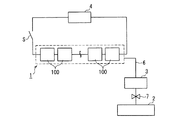
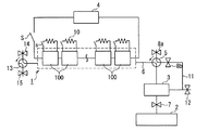
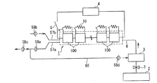
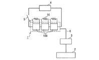
図1は、本発明の燃料電池発電システムの一例を示す概略図である。1は燃料電池であり、電気的に直列に接続された複数の第1の膜・電極接合体(MEA)100を有しており、本発明の燃料電池発電システムが適用される電子機器などの外部負荷4に接続されている。2は、燃料電池1へ燃料である水素を供給するための水素供給源としての水素製造装置である。燃料電池1と水素製造装置2との間には、燃料流路6が形成されており、燃料流路6の途中に、水素除去装置3が配置されている。7はストップバルブであり、燃料電池1の作動停止に合わせて閉じることで、水素製造装置2から燃料電池1への水素の供給を遮断し、また、燃料電池1の作動開始に合わせて開くことで、水素製造装置2から燃料電池1への水素の供給を可能とするためのものである。
(Embodiment 1)
FIG. 1 is a schematic view showing an example of a fuel cell power generation system of the present invention. Reference numeral 1 denotes a fuel cell, which has a plurality of first membrane-electrode assemblies (MEAs) 100 electrically connected in series, such as an electronic device to which the fuel cell power generation system of the present invention is applied. Connected to external load 4. Reference numeral 2 denotes a hydrogen production apparatus as a hydrogen supply source for supplying hydrogen as fuel to the fuel cell 1. A fuel flow path 6 is formed between the fuel cell 1 and the hydrogen production apparatus 2, and a hydrogen removal apparatus 3 is disposed in the middle of the fuel flow path 6. Reference numeral 7 denotes a stop valve, which is closed when the fuel cell 1 is stopped to shut off the supply of hydrogen from the hydrogen production device 2 to the fuel cell 1 and is opened when the fuel cell 1 starts operating. Thus, hydrogen can be supplied from the hydrogen production apparatus 2 to the fuel cell 1.

水素除去装置3は、外部負荷4がオフになった時、すなわち、燃料電池1から外部負荷4への電力供給が停止した際に作動させる。これによって、水素製造装置2から燃料電池1への水素供給が継続してしまう場合や、ストップバルブ7によって水素供給を停止しても燃料電池1内へ余剰水素が流れ込んでしまう場合に、水素除去装置3により、燃料電池1へ向かう水素を除去することが可能となる。その結果、燃料電池1内への水素供給がなくなるか、または、その供給量が大幅に低減される。また、水素製造装置2から供給される余剰水素の量よりも、水素除去装置3の水素除去の能力が高い場合は、水素製造装置2からの水素だけでなく、燃料電池1の内部に残存する余剰水素も除去することができる。   The hydrogen removing device 3 is operated when the external load 4 is turned off, that is, when the power supply from the fuel cell 1 to the external load 4 is stopped. As a result, when hydrogen supply from the hydrogen production device 2 to the fuel cell 1 continues or when surplus hydrogen flows into the fuel cell 1 even if the hydrogen supply is stopped by the stop valve 7, hydrogen removal is performed. The device 3 makes it possible to remove hydrogen going to the fuel cell 1. As a result, the supply of hydrogen into the fuel cell 1 is lost or the supply amount is greatly reduced. Further, when the hydrogen removal capability of the hydrogen removal device 3 is higher than the amount of surplus hydrogen supplied from the hydrogen production device 2, not only the hydrogen from the hydrogen production device 2 but also the fuel cell 1 remains. Excess hydrogen can also be removed.

水素除去装置3は、燃料電池1の作動中に作動させることもできる。例えば、水素供給量が、燃料電池1での発電に必要とされる水素の量を超える場合に、水素除去装置3を作動させて余剰の水素を除去し、燃料電池1への水素供給量を調整することもできる。   The hydrogen removing device 3 can also be operated during the operation of the fuel cell 1. For example, when the hydrogen supply amount exceeds the amount of hydrogen required for power generation in the fuel cell 1, the hydrogen removal device 3 is operated to remove excess hydrogen, and the hydrogen supply amount to the fuel cell 1 is increased. It can also be adjusted.

本発明の燃料電池発電システムは、ストップバルブ7を備えなくてもよいが、ストップバルブ7を備える場合には、図1に示すように、水素製造装置2と水素除去装置3との間に配置することが好ましい。また、図1では、外部負荷4が、スイッチ(S)を介して燃料電池1に接続された構成を示しているが、外部負荷4は燃料電池1に直接接続した状態で構成してもよい。   The fuel cell power generation system of the present invention may not include the stop valve 7, but when the stop valve 7 is provided, it is disposed between the hydrogen production apparatus 2 and the hydrogen removal apparatus 3 as shown in FIG. It is preferable to do. 1 shows a configuration in which the external load 4 is connected to the fuel cell 1 via the switch (S), but the external load 4 may be configured to be directly connected to the fuel cell 1. .

また、水素供給源としての水素製造装置2は、本発明の燃料電池発電システムに備えられていてもよく、本発明の燃料電池発電システムとは別の構成となってもよい。   Moreover, the hydrogen production apparatus 2 as a hydrogen supply source may be provided in the fuel cell power generation system of the present invention, or may have a configuration different from the fuel cell power generation system of the present invention.

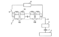
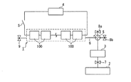
また、図2は、本発明の燃料電池発電システムの他の例を示す概略図である。図2の燃料電池発電システムは、図1に示される燃料電池発電システムの燃料電池1に備えられた個々のMEA100に、リード体などにより抵抗10を接続した例であり、その正極と負極とは、抵抗10を介して電気的に導通させることができる。   FIG. 2 is a schematic view showing another example of the fuel cell power generation system of the present invention. The fuel cell power generation system of FIG. 2 is an example in which a resistor 10 is connected to each MEA 100 provided in the fuel cell 1 of the fuel cell power generation system shown in FIG. , Electrical conduction can be achieved through the resistor 10.

図2に示す燃料電池発電システムでは、外部負荷4への電力供給が終了し、燃料電池1の作動が停止した際に、個々のMEA100の正極−負極間を繋ぐリード体に設けたスイッチ(s)を接続して正極と負極とを導通させる。これにより燃料電池1内に残留している水素を燃料として、個々のMEA100が発電を行うため、燃料電池1内の余剰水素を消費することができる。余剰水素の処理に、水素除去装置3と、燃料電池1内のMEA100とを併用することにより、水素除去装置3のみを作動させるよりも、システム内部の余剰水素をより速く消費することができるため、余剰水素による燃料電池1の劣化をより一層抑制して、燃料電池1を更に長寿命化することができる。加えて、水素除去装置3の小型化、簡略化を図ることができる。   In the fuel cell power generation system shown in FIG. 2, when the power supply to the external load 4 is finished and the operation of the fuel cell 1 is stopped, the switch (s) provided in the lead body connecting between the positive electrode and the negative electrode of each MEA 100 ) To connect the positive electrode and the negative electrode. As a result, each MEA 100 generates power using the hydrogen remaining in the fuel cell 1 as fuel, so that surplus hydrogen in the fuel cell 1 can be consumed. By using the hydrogen removal device 3 and the MEA 100 in the fuel cell 1 in combination with surplus hydrogen, surplus hydrogen inside the system can be consumed faster than operating only the hydrogen removal device 3. Further, deterioration of the fuel cell 1 due to surplus hydrogen can be further suppressed, and the life of the fuel cell 1 can be further extended. In addition, the hydrogen removal device 3 can be reduced in size and simplified.

図2の燃料電池発電システムでは、燃料電池1の各MEA100における正極と負極とを、抵抗10を介して接続しているが、抵抗10の抵抗値は、例えば、燃料電池1の作動停止後に、MEA100の正極−負極間の電圧が0.1Vまで低下するのに要する時間が1分以内となるよう設定すればよい。また、MEA100の正極と負極とは、抵抗10を用いずにリード体で直接導通させてもよい。また、燃料電池1の全てのMEA100において、正極と負極とを電気的に導通させるよう構成する必要はなく、少なくとも1つのMEA100において、正極と負極とが電気的に導通されるよう構成してもよい。例えば、水素製造装置2に近い、水素の流れの上流側に配置されたMEA100の1つあるいは複数を、余剰水素の処理に利用すれば、下流側にあるMEA100に余剰水素が流入するのを防ぐことができる。また、下流側にあるMEA100を余剰水素の処理に利用してもよく、特性劣化を生じやすい上流側のMEA100に比べて、下流側のMEA100の発電時間を長くすることにより、燃料電池1の全体として、各MEA100の特性劣化を均一に進行させ、特性のばらつきを抑制するようにしてもよい。   In the fuel cell power generation system of FIG. 2, the positive electrode and the negative electrode of each MEA 100 of the fuel cell 1 are connected via the resistor 10. The resistance value of the resistor 10 is, for example, after the operation of the fuel cell 1 is stopped, What is necessary is just to set so that the time required for the voltage between the positive electrode and negative electrode of MEA100 to fall to 0.1V may be within 1 minute. Further, the positive electrode and the negative electrode of the MEA 100 may be directly conducted by a lead body without using the resistor 10. Further, in all the MEAs 100 of the fuel cell 1, it is not necessary to configure the positive electrode and the negative electrode to be electrically connected, and in at least one MEA 100, the positive electrode and the negative electrode may be configured to be electrically connected. Good. For example, if one or more of the MEAs 100 arranged on the upstream side of the hydrogen flow close to the hydrogen production apparatus 2 are used for surplus hydrogen processing, surplus hydrogen is prevented from flowing into the MEA 100 on the downstream side. be able to. Further, the MEA 100 on the downstream side may be used for the treatment of surplus hydrogen, and the power generation time of the downstream MEA 100 is made longer as compared with the upstream MEA 100 which is likely to cause characteristic deterioration, so that the entire fuel cell 1 is As an alternative, the characteristic deterioration of each MEA 100 may be progressed uniformly to suppress variation in characteristics.

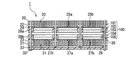
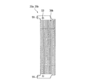
図3は、本発明の燃料電池発電システムに係る燃料電池(燃料電池モジュール)の一例を示す模式断面図である。図3は断面図であるが、各構成要素の理解を容易にするために、一部の構成要素については、断面であることを示す斜線を付していない。また、図3では、MEAの正極と負極とを電気的に導通させるための構成については、示していない。   FIG. 3 is a schematic cross-sectional view showing an example of a fuel cell (fuel cell module) according to the fuel cell power generation system of the present invention. FIG. 3 is a cross-sectional view, but in order to facilitate understanding of each component, some components are not hatched to indicate a cross section. FIG. 3 does not show a configuration for electrically connecting the positive electrode and the negative electrode of the MEA.

図3の燃料電池1は、正極拡散層101および正極触媒層102からなる正極と、固体電解質膜103と、負極拡散層105および負極触媒層104からなる負極とが、順次積層されてなるMEA100を3個備えており、これらのMEA100が平面状に配置されている。   The fuel cell 1 in FIG. 3 includes an MEA 100 in which a positive electrode including a positive electrode diffusion layer 101 and a positive electrode catalyst layer 102, a solid electrolyte membrane 103, and a negative electrode including a negative electrode diffusion layer 105 and a negative electrode catalyst layer 104 are sequentially stacked. Three MEAs 100 are arranged in a plane.

それぞれのMEA100の正極側には、正極集電プレート24、25a、25b、正極絶縁プレート22、および正極パネルプレート20が順次配置されている。また、それぞれのMEA100の負極側には、負極集電プレート26、27a、27b、負極絶縁プレート23、および負極パネルプレート21が順次配置されている。   On the positive electrode side of each MEA 100, positive electrode current collecting plates 24, 25a, 25b, a positive electrode insulating plate 22, and a positive electrode panel plate 20 are sequentially arranged. Further, negative electrode current collecting plates 26, 27 a, 27 b, a negative electrode insulating plate 23, and a negative electrode panel plate 21 are sequentially arranged on the negative electrode side of each MEA 100.

そして、全てのMEA100が、正極パネルプレート20と負極パネルプレート21とに挟持されて一体化している。また、図3では明らかにしていないが、隣り合うMEA100同士は、正極集電プレート24、25a、25bと負極集電プレート26、27a、27bとの電気的接続によって、直列に接続されている。   All the MEAs 100 are sandwiched and integrated with the positive electrode panel plate 20 and the negative electrode panel plate 21. Further, although not shown in FIG. 3, the adjacent MEAs 100 are connected in series by electrical connection between the positive electrode current collector plates 24, 25a, 25b and the negative electrode current collector plates 26, 27a, 27b.

正極集電プレート24、25a、25b、正極絶縁プレート22および正極パネルプレート20には、燃料電池1の外部の酸素を正極に導入するための酸素導入孔が複数設けられている。そして、正極集電プレート24、25a、25bの酸素導入孔、正極絶縁プレート22の酸素導入孔、および正極パネルプレート20の酸素導入孔により、正極パネルプレート20の外表面からMEA100の正極拡散層101にまで到達する正極開口部30が複数形成されており、これら正極開口部30から、燃料電池1の外部の酸素(空気)が拡散により正極拡散層101に供給される構造となっている。   The positive electrode current collecting plates 24, 25a, 25b, the positive electrode insulating plate 22, and the positive electrode panel plate 20 are provided with a plurality of oxygen introduction holes for introducing oxygen outside the fuel cell 1 into the positive electrode. The positive electrode diffusion layer 101 of the MEA 100 is formed from the outer surface of the positive electrode panel plate 20 by the oxygen introduction holes of the positive electrode current collecting plates 24, 25 a, 25 b, the oxygen introduction hole of the positive electrode insulating plate 22, and the oxygen introduction hole of the positive electrode panel plate 20. A plurality of the positive electrode openings 30 reaching the position are formed, and oxygen (air) outside the fuel cell 1 is supplied from the positive electrode openings 30 to the positive electrode diffusion layer 101 by diffusion.

また、図3の燃料電池1では、負極集電プレート26、27a、27b、負極絶縁プレート23および負極パネルプレート21には、燃料タンク部29内の燃料を負極に導入するための燃料導入孔が複数設けられている。そして、負極集電プレート26、27a、27bの燃料導入孔、負極絶縁プレート23の燃料導入孔、および負極パネルプレート21の燃料導入孔により、負極パネルプレート21の燃料タンク部29側表面からMEA100の負極拡散層105にまで到達する負極開口部31が複数形成されており、これら負極開口部31から、燃料タンク部29内の燃料が負極拡散層105に供給される構造となっている。   Further, in the fuel cell 1 of FIG. 3, the negative electrode current collecting plates 26, 27a, 27b, the negative electrode insulating plate 23, and the negative electrode panel plate 21 have fuel introduction holes for introducing the fuel in the fuel tank portion 29 into the negative electrode. A plurality are provided. Then, the fuel introduction hole of the negative electrode current collecting plates 26, 27 a, 27 b, the fuel introduction hole of the negative electrode insulating plate 23, and the fuel introduction hole of the negative electrode panel plate 21 make the MEA 100 A plurality of negative electrode openings 31 reaching the negative electrode diffusion layer 105 are formed, and the fuel in the fuel tank portion 29 is supplied from the negative electrode openings 31 to the negative electrode diffusion layer 105.

図3の燃料電池1では、正極パネルプレート20と負極パネルプレート21、更には燃料タンク部29は、ボルト32とナット33によって固定されている。また、図3において、28aおよび28bはシール材である。   In the fuel cell 1 of FIG. 3, the positive electrode panel plate 20, the negative electrode panel plate 21, and the fuel tank portion 29 are fixed by bolts 32 and nuts 33. Moreover, in FIG. 3, 28a and 28b are sealing materials.

正極拡散層101および負極拡散層105は、多孔性の電子伝導性材料などから構成され、例えば、撥水処理を施した多孔質炭素シートなどが用いられる。正極拡散層101や負極拡散層105の触媒層側には、更なる撥水性向上および触媒層との接触性向上を目的として、フッ素樹脂粒子〔ポリテトラフルオロエチレン(PTFE)樹脂粒子など〕を含む炭素粉末のペーストが塗布されている場合もある。   The positive electrode diffusion layer 101 and the negative electrode diffusion layer 105 are made of a porous electron conductive material or the like, for example, a porous carbon sheet subjected to a water repellent treatment. The catalyst layer side of the positive electrode diffusion layer 101 and the negative electrode diffusion layer 105 contains fluororesin particles (polytetrafluoroethylene (PTFE) resin particles, etc.) for the purpose of further improving water repellency and improving contact with the catalyst layer. A carbon powder paste may be applied.

正極触媒層102は、正極拡散層101を介して拡散してきた酸素を還元する機能を有している。正極触媒層102は、例えば、触媒を担持した炭素粉末(触媒担持炭素粉末)と、プロトン伝導性材料とを含有している。また、必要に応じて、樹脂などのバインダを更に含有していてもよい。   The positive electrode catalyst layer 102 has a function of reducing oxygen diffused through the positive electrode diffusion layer 101. The positive electrode catalyst layer 102 contains, for example, carbon powder carrying a catalyst (catalyst carrying carbon powder) and a proton conductive material. Moreover, you may further contain binders, such as resin, as needed.

正極触媒層102に用いる触媒としては、酸素を還元できるものであれば特に制限はないが、例えば、白金微粒子が挙げられる。また、上記触媒は、鉄、ニッケル、コバルト、錫、ルテニウムおよび金よりなる群から選ばれる少なくとも1種の金属元素と白金との合金で構成される微粒子などであってもよい。   The catalyst used for the positive electrode catalyst layer 102 is not particularly limited as long as it can reduce oxygen, and examples thereof include platinum fine particles. The catalyst may be fine particles composed of an alloy of platinum and at least one metal element selected from the group consisting of iron, nickel, cobalt, tin, ruthenium and gold.

上記触媒の担体である炭素粉末としては、例えば、BET比表面積が10〜2000m2/gであり、平均粒子径が20〜100nmのカーボンブラックなどが用いられる。炭素粉末への上記触媒の担持は、例えば、コロイド法などで行なうことができる。 Examples of the carbon powder that is the carrier for the catalyst include carbon black having a BET specific surface area of 10 to 2000 m 2 / g and an average particle diameter of 20 to 100 nm. The catalyst can be supported on the carbon powder by, for example, a colloid method.

上記炭素粉末と上記触媒との含有比率としては、例えば、炭素粉末100質量部に対して、触媒が5〜400質量部であることが好ましい。このような含有比率であれば、十分な触媒活性を有する正極触媒層が構成できるからである。また、例えば、炭素粉末上に触媒を析出させる方法(例えば、コロイド法)で触媒担持炭素粉末が作製される場合には、炭素粉末と触媒とが上記含有比率であれば、触媒の径が大きくなりすぎず、十分な触媒活性が得られるからである。   As a content ratio of the carbon powder and the catalyst, for example, the catalyst is preferably 5 to 400 parts by mass with respect to 100 parts by mass of the carbon powder. This is because such a content ratio can constitute a positive electrode catalyst layer having sufficient catalytic activity. Further, for example, when the catalyst-supported carbon powder is produced by a method of depositing the catalyst on the carbon powder (for example, a colloid method), the catalyst diameter is large if the carbon powder and the catalyst have the above content ratio. This is because sufficient catalytic activity is obtained without becoming too much.

正極触媒層102に含まれるプロトン伝導性材料としては、特に制限はないが、例えば、ポリパーフルオロスルホン酸樹脂、スルホン化ポリエーテルスルホン酸樹脂、スルホン化ポリイミド樹脂などのスルホン酸基を有する樹脂を用いることができる。ポリパーフルオロスルホン酸樹脂としては、具体的には、デュポン社製の「ナフィオン(登録商標)」、旭硝子社製の「フレミオン(登録商標)」、旭化成工業社製の「アシプレックス(商品名)」などが挙げられる。   The proton conductive material contained in the positive electrode catalyst layer 102 is not particularly limited. For example, a resin having a sulfonic acid group such as a polyperfluorosulfonic acid resin, a sulfonated polyether sulfonic acid resin, or a sulfonated polyimide resin is used. Can be used. Specific examples of the polyperfluorosulfonic acid resin include “Nafion (registered trademark)” manufactured by DuPont, “Flemion (registered trademark)” manufactured by Asahi Glass, and “Aciplex (trade name) manufactured by Asahi Kasei Kogyo Co., Ltd. Or the like.

正極触媒層102におけるプロトン伝導性材料の含有量は、触媒担持炭素粉末100質量部に対して、2〜200質量部であることが好ましい。プロトン伝導性材料が上記の量で含有されていれば、正極触媒層において十分なプロトン伝導性が得られ、電気抵抗値が大きくなりすぎず、電池性能の良好な燃料電池を得ることができるからである。   The content of the proton conductive material in the positive electrode catalyst layer 102 is preferably 2 to 200 parts by mass with respect to 100 parts by mass of the catalyst-carrying carbon powder. If the proton conductive material is contained in the above amount, sufficient proton conductivity is obtained in the positive electrode catalyst layer, and the electric resistance value does not become too large, and a fuel cell with good battery performance can be obtained. It is.

正極触媒層102に用いるバインダとしては、特に制限はないが、例えば、ポリテトラフルオロエチレン(PTFE)、テトラフルオロエチレン−パーフルオロアルキルビニルエーテル共重合体(PFA)、テトラフルオロエチレン−ヘキサフルオロプロピレン共重合体(FEP)、テトラフルオロエチレン−エチレン共重合体(E/TFE)、ポリビニリデンフルオライド(PVDF)およびポリクロロトリフルオロエチレン(PCTFE)などのフッ素樹脂や、ポリエチレン、ポリプロピレン、ナイロン、ポリスチレン、ポリエステル、アイオノマー、ブチルゴム、エチレン・酢酸ビニル共重合体、エチレン・エチルアクリレート共重合体およびエチレン・アクリル酸共重合体などの非フッ素樹脂などを用いることができる。   The binder used for the positive electrode catalyst layer 102 is not particularly limited. For example, polytetrafluoroethylene (PTFE), tetrafluoroethylene-perfluoroalkyl vinyl ether copolymer (PFA), tetrafluoroethylene-hexafluoropropylene copolymer Fluororesin such as coalescence (FEP), tetrafluoroethylene-ethylene copolymer (E / TFE), polyvinylidene fluoride (PVDF) and polychlorotrifluoroethylene (PCTFE), polyethylene, polypropylene, nylon, polystyrene, polyester Further, non-fluorine resins such as ionomer, butyl rubber, ethylene / vinyl acetate copolymer, ethylene / ethyl acrylate copolymer, and ethylene / acrylic acid copolymer can be used.

正極触媒層102におけるバインダの含有量は、触媒担持炭素粉末100質量部に対して、0.01〜100質量部であることが好ましい。バインダが上記の量で含有されていれば、正極触媒層について十分な結着性が得られ、電気抵抗値が大きくなりすぎず、電池性能の良好な燃料電池を得ることができるからである。   The binder content in the positive electrode catalyst layer 102 is preferably 0.01 to 100 parts by mass with respect to 100 parts by mass of the catalyst-supporting carbon powder. This is because if the binder is contained in the above-mentioned amount, sufficient binding properties can be obtained for the positive electrode catalyst layer, and the electric resistance value does not become too large, and a fuel cell with good battery performance can be obtained.

負極触媒層104は、負極拡散層105を介して拡散してきた水素などの燃料を酸化する機能を有している。負極触媒層104は、例えば、触媒を担持した炭素粉末(触媒担持炭素粉末)と、プロトン伝導性材料とを含有している。必要に応じて、樹脂などのバインダを更に含有していてもよい。   The negative electrode catalyst layer 104 has a function of oxidizing a fuel such as hydrogen diffused through the negative electrode diffusion layer 105. The negative electrode catalyst layer 104 contains, for example, carbon powder carrying a catalyst (catalyst carrying carbon powder) and a proton conductive material. If necessary, a binder such as a resin may be further contained.

負極触媒層104に用いる触媒は、水素などの燃料を酸化できれば特に制限はなく、例えば、正極触媒層102に用いる触媒として例示した前述の各触媒を用いることができる。負極触媒層104に用いる炭素粉末、プロトン伝導性材料、およびバインダについても、正極触媒層102に用いる炭素粉末、プロトン伝導性材料、およびバインダとして例示した前述の各材料を用いることができる。   The catalyst used for the negative electrode catalyst layer 104 is not particularly limited as long as a fuel such as hydrogen can be oxidized. For example, the above-described catalysts exemplified as the catalyst used for the positive electrode catalyst layer 102 can be used. As the carbon powder, proton conductive material, and binder used for the negative electrode catalyst layer 104, the above-described materials exemplified as the carbon powder, proton conductive material, and binder used for the positive electrode catalyst layer 102 can be used.

固体電解質膜103は、プロトンを輸送可能であり、且つ電子伝導性を示さない材料で構成された膜であれば、特に制限はない。固体電解質膜103を構成し得る材料としては、例えば、ポリパーフルオロスルホン酸樹脂、具体的には、デュポン社製の「ナフィオン(登録商標)」、旭硝子社製の「フレミオン(登録商標)」、旭化成工業社製の「アシプレックス(商品名)」などが挙げられる。その他、スルホン化ポリエーテルスルホン酸樹脂、スルホン化ポリイミド樹脂、硫酸ドープポリベンズイミダゾールなども、固体電解質膜103の材料として用いることができる。   The solid electrolyte membrane 103 is not particularly limited as long as it is a membrane made of a material that can transport protons and does not exhibit electron conductivity. As a material that can constitute the solid electrolyte membrane 103, for example, polyperfluorosulfonic acid resin, specifically, "Nafion (registered trademark)" manufactured by DuPont, "Flemion (registered trademark)" manufactured by Asahi Glass, Examples include “Aciplex (trade name)” manufactured by Asahi Kasei Corporation. In addition, sulfonated polyether sulfonic acid resin, sulfonated polyimide resin, sulfuric acid-doped polybenzimidazole, and the like can also be used as the material of the solid electrolyte membrane 103.

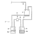
図4は、本発明の燃料電池発電システムに係る水素供給源の一例を示す模式図である。図4に示す水素供給源は、水素発生物質に対して連続的または断続的に水を供給し、水素発生物質と水とを反応させて水素を発生させる機構を有する水素製造装置の構成例である。   FIG. 4 is a schematic diagram showing an example of a hydrogen supply source according to the fuel cell power generation system of the present invention. The hydrogen supply source shown in FIG. 4 is a configuration example of a hydrogen production apparatus having a mechanism for supplying water continuously or intermittently to a hydrogen generating substance and generating hydrogen by reacting the hydrogen generating substance with water. is there.

水素供給源である水素製造装置2は、水素発生物質34aを収容する水素発生物質収容容器34と、水35aを収容する水収容容器35とを備えており、水素発生物質収容容器34に、水収容容器35から水35aを供給し、水素発生物質収容容器34内において水素発生物質34aと水35aとを反応させて水素を製造する。よって、水素発生物質収容容器34は、水素発生物質34aと水35aとの反応容器としての役割も担っている。水素発生物質収容容器34で発生した水素は、水素導出パイプ39、40で構成される燃料流路を経て、燃料電池に供給される。   The hydrogen production apparatus 2 that is a hydrogen supply source includes a hydrogen generating substance storage container 34 that stores a hydrogen generating substance 34a and a water storage container 35 that stores water 35a. Water 35a is supplied from the storage container 35, and hydrogen is produced by reacting the hydrogen generation substance 34a with the water 35a in the hydrogen generation substance storage container 34. Therefore, the hydrogen generating substance storage container 34 also serves as a reaction container for the hydrogen generating substance 34a and the water 35a. The hydrogen generated in the hydrogen generating substance storage container 34 is supplied to the fuel cell through the fuel flow path constituted by the hydrogen outlet pipes 39 and 40.

水収容容器35から水素発生物質収容容器34に水35aを供給する水供給パイプ38には、水供給ポンプ36が設けられている。水収容容器35に収容する水35aは、中性の水、酸性水溶液、アルカリ性水溶液など、少なくとも水を含む液体であればよく、使用する水素発生物質34aとの反応性などに応じて好適なものを選択すればよい。   A water supply pipe 36 that supplies water 35 a from the water storage container 35 to the hydrogen generating substance storage container 34 is provided with a water supply pump 36. The water 35a stored in the water storage container 35 may be a liquid containing at least water, such as neutral water, an acidic aqueous solution, or an alkaline aqueous solution, and is suitable depending on the reactivity with the hydrogen generating material 34a used. Should be selected.

水素発生物質収容容器34および水収容容器35は脱着式とすることもできる。これにより、水素発生物質収容容器34内の水素発生物質34aが消費されつくしたり、水収容容器35内の水35aがなくなったりした場合に、これらを取り外し、水素発生物質34aが充填された水素発生物質収容容器34や水35aが充填された水収容容器35を新たに取り付けることで、再び水素製造を行うことが可能となる。   The hydrogen generating substance storage container 34 and the water storage container 35 may be detachable. As a result, when the hydrogen generating material 34a in the hydrogen generating material storage container 34 is consumed or the water 35a in the water storage container 35 is exhausted, these are removed and the hydrogen generating material filled with the hydrogen generating material 34a is generated. By newly attaching the substance container 34 and the water container 35 filled with the water 35a, hydrogen production can be performed again.

水素発生物質収容容器34に収容される水素発生物質34aとしては、特に制限はないが、水と120℃以下の低温で反応して水素を発生し得るものが望ましい。例えば、アルミニウム、ケイ素、亜鉛、マグネシウムといった金属;アルミニウム、ケイ素、亜鉛、およびマグネシウムより選ばれる1種以上の元素を50質量%以上、好ましくは80質量%以上、より好ましくは90質量%以上含有する合金;金属水素化物;などが好適に使用できる。   Although there is no restriction | limiting in particular as the hydrogen generating substance 34a accommodated in the hydrogen generating substance accommodating container 34, The thing which can react with water at the low temperature of 120 degrees C or less and generate | occur | produces hydrogen is desirable. For example, a metal such as aluminum, silicon, zinc, magnesium; one or more elements selected from aluminum, silicon, zinc, and magnesium are contained in an amount of 50% by mass or more, preferably 80% by mass or more, more preferably 90% by mass or more. Alloys, metal hydrides, and the like can be preferably used.

上記金属や合金からなる水素発生物質は、表面に酸化皮膜を形成して安定化する。このため、反応性を高めるためには、水素発生物質の粒径をできるだけ小さくし、反応面積を大きくすることが好ましい。例えば、水素発生物質粒子の平均粒径は、100μm以下であることが好ましく、50μm以下であることがより好ましい。また、粒子形状は、反応効率を高めるためにフレークであることが好ましい。粒径が小さすぎると、嵩密度が小さくなり、充填密度が低下するだけでなく、取り扱いが困難になるため、水素発生物質の粒径は、0.1μm以上とすることが好ましい。   The hydrogen generating material composed of the above metal or alloy is stabilized by forming an oxide film on the surface. For this reason, in order to increase the reactivity, it is preferable to make the particle size of the hydrogen generating material as small as possible and increase the reaction area. For example, the average particle diameter of the hydrogen generating substance particles is preferably 100 μm or less, and more preferably 50 μm or less. The particle shape is preferably flakes in order to increase reaction efficiency. If the particle size is too small, the bulk density is reduced, the packing density is lowered, and handling becomes difficult. Therefore, the particle size of the hydrogen generating material is preferably 0.1 μm or more.

平均粒径の測定方法としては、例えば、レーザー回折・散乱法などを用いることができる。具体的には、水などの液相に分散させた測定対象物質にレーザー光を照射することによって検出される散乱強度分布を利用した粒子径分布の測定方法である。レーザー回折・散乱法による粒子径分布測定装置としては、例えば、日機装株式会社製の「マイクロトラックHRA」などを用いることができる。   As a method for measuring the average particle diameter, for example, a laser diffraction / scattering method or the like can be used. Specifically, this is a particle diameter distribution measurement method using a scattering intensity distribution detected by irradiating a measurement target substance dispersed in a liquid phase such as water with laser light. As a particle size distribution measuring apparatus using a laser diffraction / scattering method, for example, “Microtrack HRA” manufactured by Nikkiso Co., Ltd. can be used.

また、水素発生物質として用い得る金属水素化物としては、例えば、水素化ホウ素ナトリウムまたは水素化ホウ素カリウムなどが挙げられる。これらの金属水素化物は、アルカリ水溶液中では比較的安定であるが、触媒が存在する場合、速やかに水と反応して水素を発生することができる。触媒としては例えばPt、Niなどの金属や酸などを用いることができる。   Examples of the metal hydride that can be used as the hydrogen generating substance include sodium borohydride and potassium borohydride. These metal hydrides are relatively stable in an aqueous alkali solution, but when a catalyst is present, they can rapidly react with water to generate hydrogen. As the catalyst, for example, metals such as Pt and Ni, acids, and the like can be used.

水素発生物質は、上記例示のものを1種単独で用いてもよく、2種以上を併用してもよい。   As the hydrogen generating substance, those exemplified above may be used alone or in combination of two or more.

上記水素発生物質は、水との反応性を高めるため、水と混合された状態で加熱してもよく、加熱された水を供給してもよい。   In order to increase the reactivity with water, the hydrogen generating substance may be heated in a state of being mixed with water, or heated water may be supplied.

また、上記水素発生物質を、水と反応して発熱する発熱物質(水素発生物質以外の物質)と共に用いることにより、低温(例えば5℃程度)の水を供給しても、上記発熱物質の発熱によって反応系内の温度を高めて、迅速な水素発生を可能とし得る。   Further, by using the hydrogen generating material together with a heat generating material that generates heat by reacting with water (a material other than the hydrogen generating material), the heat generation of the heat generating material can be achieved even when low temperature water (for example, about 5 ° C.) is supplied. Thus, the temperature in the reaction system can be increased to enable rapid hydrogen generation.

水と反応して発熱する発熱物質は、例えば、酸化カルシウム、酸化マグネシウム、塩化カルシウム、塩化マグネシウム、硫酸カルシウムなど、水との反応により水酸化物となるか、あるいは、水和することにより発熱するアルカリ金属またはアルカリ土類金属の酸化物、塩化物、硫酸化合物などを例示することができる。また、水素化ホウ素ナトリウム、水素化ホウ素カリウム、水素化リチウムなどの金属水素化物などのように水との反応により水素を生成するものは、前述の通り、水素発生物質として使用することが可能であるが、発熱物質としても用いることができる。   The exothermic substance that generates heat by reacting with water, for example, calcium oxide, magnesium oxide, calcium chloride, magnesium chloride, calcium sulfate, etc., becomes a hydroxide upon reaction with water, or generates heat when hydrated. Examples include alkali metal or alkaline earth metal oxides, chlorides, sulfate compounds, and the like. In addition, those that generate hydrogen by reaction with water, such as metal hydrides such as sodium borohydride, potassium borohydride, and lithium hydride, can be used as a hydrogen generating substance as described above. However, it can also be used as a pyrogen.

特に、水素発生物質として、アルミニウム、ケイ素、亜鉛、マグネシウムといった金属や、アルミニウム、ケイ素、亜鉛、およびマグネシウムの中の1種以上の元素を主体とする合金を使用する場合には、上記発熱物質を併用することが好ましい。他方、水素発生物質として上記金属水素化物を用いる場合には、発熱物質を併用しなくても、比較的良好な速度で水素を製造できるが、発熱物質を併用して、更に水素発生速度を高めてもよい。   In particular, when a metal such as aluminum, silicon, zinc, or magnesium or an alloy mainly composed of one or more elements selected from aluminum, silicon, zinc, and magnesium is used as the hydrogen generating substance, the above exothermic substance is used. It is preferable to use together. On the other hand, when the above metal hydride is used as a hydrogen generating material, hydrogen can be produced at a relatively good rate without using any exothermic material. May be.

水素発生物質収容容器34は、水素を発生させる水素発生物質34aを収納可能であれば、その材質や形状は特に限定されないが、水の供給口や水素の導出口以外から水や水素が漏れない材質や形状が好ましい。具体的な容器の材質としては、水および水素を透過しにくく、且つ120℃程度に加熱しても容器が破損しない材質が好ましく、例えば、アルミニウム、鉄などの金属、ポリエチレン、ポリプロピレンなどの樹脂を用いることができる。また、容器の形状としては、角柱状、円柱状などが採用できる。   The material and shape of the hydrogen generating substance storage container 34 are not particularly limited as long as it can store the hydrogen generating substance 34a that generates hydrogen, but water and hydrogen do not leak from other than the water supply port and the hydrogen outlet. Material and shape are preferred. As a specific material of the container, a material that is difficult to permeate water and hydrogen and that does not break even when heated to about 120 ° C. is preferable. For example, a metal such as aluminum or iron, or a resin such as polyethylene or polypropylene is used. Can be used. Further, as the shape of the container, a prismatic shape, a cylindrical shape or the like can be adopted.

水収容容器35については特に制限はなく、例えば、従来の水素製造装置と同様の水を収容するタンクなどが採用できる。   There is no restriction | limiting in particular about the water storage container 35, For example, the tank etc. which store the water similar to the conventional hydrogen production apparatus are employable.

水収容容器35中の水35aが、水供給パイプ38を通じて水素発生物質収容容器34に供給されることで、水素発生物質収容容器34内の水素発生物質34aと反応して水素を発生するが、水素発生物質収容容器34内に存在する未反応の水が、発生した水素中に混入し、これらの混合物が水素導出パイプ40を通じて燃料電池側に流入する場合がある。   The water 35a in the water storage container 35 is supplied to the hydrogen generation substance storage container 34 through the water supply pipe 38, thereby reacting with the hydrogen generation substance 34a in the hydrogen generation substance storage container 34 to generate hydrogen. In some cases, unreacted water present in the hydrogen generating substance storage container 34 is mixed into the generated hydrogen, and the mixture of these flows into the fuel cell side through the hydrogen outlet pipe 40.

そこで、水素製造装置2には、燃料電池に水素を供給する燃料流路の途中に、凝縮水分離器37を設けることが好ましい。図4に示すように、水素発生物質収容容器34から排出される水素ガスは、水素導出パイプ39を通って凝縮水分離器37に導入される。この間、水素ガスに含まれる水分は、水素導出パイプ39内で冷却され凝縮水となる。凝縮水は、重力によって凝縮水分離器37の下部に落下するため、水素ガスを水と分離することができる。分離された水素ガスは、水素導出パイプ40を介して燃料電池側に供給される。   Therefore, the hydrogen production apparatus 2 is preferably provided with a condensed water separator 37 in the middle of the fuel flow path for supplying hydrogen to the fuel cell. As shown in FIG. 4, the hydrogen gas discharged from the hydrogen generating material container 34 is introduced into the condensed water separator 37 through the hydrogen outlet pipe 39. During this time, moisture contained in the hydrogen gas is cooled in the hydrogen outlet pipe 39 to become condensed water. Since condensed water falls to the lower part of the condensed water separator 37 by gravity, hydrogen gas can be separated from water. The separated hydrogen gas is supplied to the fuel cell side through the hydrogen outlet pipe 40.

また、図4に示すように、凝縮水分離器37と水収容容器35とを水回収パイプ41で連結すれば、凝縮水分離器37で分離した水を水収容容器35に回収することができる。分離した水を回収することにより、水素発生のために供給する水の効率的な利用が可能となり、水収容容器35をよりコンパクトにすることができる。   Further, as shown in FIG. 4, if the condensed water separator 37 and the water storage container 35 are connected by the water recovery pipe 41, the water separated by the condensed water separator 37 can be recovered in the water storage container 35. . By collecting the separated water, it is possible to efficiently use the water supplied for hydrogen generation, and the water container 35 can be made more compact.

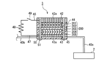
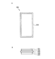
図5は、本発明の燃料電池発電システムに係る水素除去装置の一例を示す模式断面図である。図5では、水素除去装置3のみを断面で示しているが、水素除去装置3の各構成要素の理解を容易にするために、一部の構成要素については、断面であることを示す斜線を付していない。   FIG. 5 is a schematic cross-sectional view showing an example of a hydrogen removal apparatus according to the fuel cell power generation system of the present invention. In FIG. 5, only the hydrogen removal device 3 is shown in cross section, but in order to facilitate understanding of each component of the hydrogen removal device 3, some of the components are hatched indicating that they are in cross section. Not attached.

図5に示す水素除去装置3は、正極と負極とを電気的に導通させることができるよう構成された第2のMEA200を備えている。MEA200は、酸素を還元する正極触媒層202と、水素を酸化する負極触媒層204とを有しており、更に、正極触媒層202と負極触媒層204との間に固体電解質膜203を備えている。また、正極触媒層202の固体電解質膜203と接する面の反対側には、正極拡散層201が積層されており、負極触媒層204の固体電解質膜203と接する面の反対側には、負極拡散層205が積層されている。これらは図3で説明した燃料電池1に係る第1のMEA100と同様の材料で構成することができる。   The hydrogen removal apparatus 3 shown in FIG. 5 includes a second MEA 200 configured to be able to electrically connect the positive electrode and the negative electrode. The MEA 200 includes a positive electrode catalyst layer 202 that reduces oxygen and a negative electrode catalyst layer 204 that oxidizes hydrogen, and further includes a solid electrolyte membrane 203 between the positive electrode catalyst layer 202 and the negative electrode catalyst layer 204. Yes. A positive electrode diffusion layer 201 is laminated on the opposite side of the surface of the positive electrode catalyst layer 202 that contacts the solid electrolyte membrane 203, and a negative electrode diffusion layer is formed on the opposite side of the surface of the negative electrode catalyst layer 204 that contacts the solid electrolyte membrane 203. A layer 205 is stacked. These can be made of the same material as that of the first MEA 100 according to the fuel cell 1 described in FIG.

MEA200は、正極拡散層201の上部に配置された正極集電板42と、負極拡散層205の下部に配置された負極集電板43とで挟持されており、正極集電板42と負極集電板43とは、例えばボルト50とナット51により固定されている。44はシリコンゴムなどからなるシール材であり、45はタンク部(水素タンク部)である。   The MEA 200 is sandwiched between a positive electrode current collector plate 42 disposed above the positive electrode diffusion layer 201 and a negative electrode current collector plate 43 disposed below the negative electrode diffusion layer 205. The electric plate 43 is fixed by bolts 50 and nuts 51, for example. 44 is a sealing material made of silicon rubber or the like, and 45 is a tank part (hydrogen tank part).

水素除去装置3は、燃料流路である水素導出パイプ40aを介して水素製造装置2と連結され、水素製造装置2から供給される水素は、水素除去装置3の内部を通過し、燃料流路である水素供給パイプ40bを介して燃料電池に供給される。   The hydrogen removal device 3 is connected to the hydrogen production device 2 via a hydrogen lead-out pipe 40a that is a fuel flow path, and hydrogen supplied from the hydrogen production device 2 passes through the interior of the hydrogen removal device 3 and flows into the fuel flow path. The fuel cell is supplied through a hydrogen supply pipe 40b.

正極集電板42および負極集電板43は、例えば、白金、金などの貴金属や、ステンレス鋼などの耐食性金属、またはカーボンなどから構成されている。また、耐食性向上のために、それらの材料の表面にメッキや塗装が施されている場合もある。   The positive electrode current collector plate 42 and the negative electrode current collector plate 43 are made of, for example, a noble metal such as platinum or gold, a corrosion-resistant metal such as stainless steel, or carbon. Moreover, in order to improve corrosion resistance, the surface of these materials may be plated or painted.

正極集電板42には複数の空気孔42aが形成されており、これら空気孔42aを通じて大気中の酸素がMEA200の正極に供給されるようになっている。一方、タンク部45へ流入する余剰の水素は、負極集電板43に形成された複数の水素導入孔43aを通じてMEA200の負極に供給される。   A plurality of air holes 42 a are formed in the positive electrode current collector plate 42, and oxygen in the atmosphere is supplied to the positive electrode of the MEA 200 through these air holes 42 a. On the other hand, surplus hydrogen flowing into the tank portion 45 is supplied to the negative electrode of the MEA 200 through a plurality of hydrogen introduction holes 43 a formed in the negative electrode current collector plate 43.

正極集電板42の端部には正極リード線46が、負極集電板43の端部には負極リード線47が、それぞれ接続されている。また、これらのリード線46、47は、抵抗48およびスイッチ49を介して接続されている。そして、燃料電池1の作動が停止した時、すなわち外部負荷が切断された時に、スイッチ49をオンにしてMEA200の正極−負極間を導通させることで、水素除去装置3内に流入する余剰の水素を消費できる。これにより、水素除去装置3から水素供給パイプ40bを経て燃料電池へ向かう余剰の水素を完全に無くすか、またはその量を大幅に低減することができる。   A positive electrode lead wire 46 is connected to the end portion of the positive electrode current collector plate 42, and a negative electrode lead wire 47 is connected to the end portion of the negative electrode current collector plate 43. The lead wires 46 and 47 are connected via a resistor 48 and a switch 49. Then, when the operation of the fuel cell 1 is stopped, that is, when the external load is disconnected, the surplus hydrogen flowing into the hydrogen removing device 3 is turned on by turning on the switch 49 and conducting between the positive electrode and the negative electrode of the MEA 200. Can be consumed. Thereby, the excess hydrogen which goes to the fuel cell from the hydrogen removal apparatus 3 via the hydrogen supply pipe 40b can be completely eliminated, or the amount thereof can be greatly reduced.

図5に示す水素除去装置3では、MEA200の正極と負極とを、抵抗48を介して接続しているが、抵抗48の抵抗値は、例えば、燃料電池の作動停止後に、MEA200の正極−負極間の電圧が0.1Vまで低下するのに要する時間が1分以内となるよう設定すればよい。また、MEA200の正極と負極とは、抵抗48を用いずにリード体で直接導通させるのでもよいし、得られる電流を二次電池に充電するか、機器の作動に利用するのであってもよい。   In the hydrogen removal apparatus 3 shown in FIG. 5, the positive electrode and the negative electrode of the MEA 200 are connected via the resistor 48. The resistance value of the resistor 48 is, for example, the positive electrode-negative electrode of the MEA 200 after the operation of the fuel cell is stopped. What is necessary is just to set so that the time required for the voltage between them to fall to 0.1V may be within 1 minute. Further, the positive electrode and the negative electrode of the MEA 200 may be directly conducted by the lead body without using the resistor 48, or the obtained current may be charged to the secondary battery or used for the operation of the device. .

また、水素除去装置3と燃料電池とを連結する水素供給パイプ40bには、水素製造装置2から燃料電池へ向かう余剰水素を燃料電池発電システムの系外に排出できるようにコックなどの排出部を設けていてもよい。この場合には、上記排出部によって、燃料電池の作動停止時に水素製造装置2から燃料電池へ流入する余剰水素を燃料電池発電システムの系外に排出して、上記水素による燃料電池の劣化をより確実に防止することができる。水素をそのまま系外に排出すると、引火などの危険を生じる場合もあるが、水素除去装置3により、外部に排出される余剰水素を低減すれば、上記危険を回避することも可能である。   The hydrogen supply pipe 40b connecting the hydrogen removal device 3 and the fuel cell is provided with a discharge portion such as a cock so that excess hydrogen from the hydrogen production device 2 to the fuel cell can be discharged out of the fuel cell power generation system. It may be provided. In this case, surplus hydrogen that flows into the fuel cell from the hydrogen production apparatus 2 when the fuel cell is stopped is discharged out of the fuel cell power generation system by the discharge unit, thereby further deteriorating the fuel cell due to the hydrogen. It can be surely prevented. If the hydrogen is discharged out of the system as it is, there may be a risk of ignition or the like, but if the excess hydrogen discharged to the outside is reduced by the hydrogen removing device 3, the above-mentioned danger can be avoided.

(実施形態2)
上記実施形態1の燃料電池発電システムにおいて、燃料電池1の気密性を高くした場合には、水素除去装置3を作動させると、燃料電池1内の残留水素が消費されて内圧が低下し過ぎる場合がある。内圧の必要以上の低下を防ぐため、本発明の燃料電池発電システムでは、ある程度残留水素が消費された段階で、外気を燃料電池1内に取り込むようにしてもよい。例えば、燃料流路6などにコックなどの外気導入部を設けていてもよい。また、以下に示す、流路切替え部により、燃料電池1への水素の流入と外気取り込みとを切替え可能としてもよい。
(Embodiment 2)
In the fuel cell power generation system of the first embodiment, when the air tightness of the fuel cell 1 is increased, when the hydrogen removing device 3 is operated, the residual hydrogen in the fuel cell 1 is consumed and the internal pressure is too low. There is. In order to prevent the internal pressure from being lowered more than necessary, the fuel cell power generation system of the present invention may take outside air into the fuel cell 1 when the residual hydrogen is consumed to some extent. For example, an outside air introduction part such as a cock may be provided in the fuel flow path 6 or the like. Further, the flow switching unit shown below may switch between the inflow of hydrogen into the fuel cell 1 and the intake of outside air.

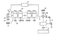
図6は、上記流路切替え部を設けた本発明の燃料電池発電システムの一例を示す概略図である。図6の燃料電池発電システムは、燃料流路6の途中に流路切替え部5を設け、燃料電池1に逆流防止弁9を設けた以外は、図1に示される燃料電池発電システムと同様の構成を有する。   FIG. 6 is a schematic diagram showing an example of the fuel cell power generation system of the present invention provided with the flow path switching unit. The fuel cell power generation system in FIG. 6 is the same as the fuel cell power generation system shown in FIG. 1 except that the flow path switching unit 5 is provided in the middle of the fuel flow path 6 and the backflow prevention valve 9 is provided in the fuel cell 1. It has a configuration.

図6では、水素製造装置2および水素除去装置3から燃料電池1へ向かう水素の流通を可能とする状態を示しているが、流路切替え部5を矢印の方向に90度回転させることにより、燃料流路6内の水素の流通を不可能にして、水素除去装置3から燃料電池1への水素の流入を遮断し、且つ燃料電池1内へ外気を取り込み可能とすることができる。8aおよび8bは開閉弁であり、流路切替え部5を図6に示す状態から矢印の方向に90度回転させた際に、燃料電池1内へ取り込む外気量を調節するためのものである。また、逆流防止弁9は、燃料電池1の内部から系外に向けて、気体を一方向のみに流すことを可能とする弁である。水素製造装置2から燃料電池1へ過剰な水素を供給した場合に、逆流防止弁9が作動すれば、この水素を系外へ排出することができ、且つ燃料電池1の運転時には外気が燃料電池1内に入るのを防ぐことができる。水素除去装置3だけでは過剰な水素を処理できない場合であっても、逆流防止弁9が作動すれば、外部に水素を排出することができる。あるいは、逆流防止弁9の向きを逆にし、燃料電池1内の圧力が低下した場合に、外気を燃料電池1内に取り込むことができるようにしてもよい。   FIG. 6 shows a state in which hydrogen can flow from the hydrogen production device 2 and the hydrogen removal device 3 to the fuel cell 1, but by rotating the flow path switching unit 5 in the direction of the arrow by 90 degrees, It is possible to disable the flow of hydrogen in the fuel flow path 6, block the flow of hydrogen from the hydrogen removal device 3 to the fuel cell 1, and allow outside air to be taken into the fuel cell 1. 8a and 8b are on-off valves for adjusting the amount of outside air taken into the fuel cell 1 when the flow path switching unit 5 is rotated 90 degrees in the direction of the arrow from the state shown in FIG. The backflow prevention valve 9 is a valve that allows gas to flow in only one direction from the inside of the fuel cell 1 toward the outside of the system. When excessive hydrogen is supplied from the hydrogen production device 2 to the fuel cell 1, if the backflow prevention valve 9 is operated, this hydrogen can be discharged out of the system, and the outside air is discharged from the fuel cell 1 during operation of the fuel cell 1. 1 can be prevented from entering. Even if the hydrogen removal device 3 alone cannot handle excess hydrogen, if the backflow prevention valve 9 is activated, hydrogen can be discharged to the outside. Alternatively, the direction of the backflow prevention valve 9 may be reversed so that outside air can be taken into the fuel cell 1 when the pressure in the fuel cell 1 decreases.

また、7はストップバルブであり、燃料電池1の作動停止に合わせて閉じることで、水素製造装置2から燃料電池1への水素の供給を遮断し、また、燃料電池1の作動開始に合わせて開くことで、水素製造装置2から燃料電池1への水素の供給を可能とするためのものである。   Reference numeral 7 denotes a stop valve, which is closed when the operation of the fuel cell 1 is stopped, thereby shutting off the supply of hydrogen from the hydrogen production device 2 to the fuel cell 1, and according to the start of operation of the fuel cell 1. By opening, hydrogen can be supplied from the hydrogen production apparatus 2 to the fuel cell 1.

水素除去装置3の作動に関しては、実施態様1の燃料電池発電システムの水素除去装置と同様に行うことができる。   The operation of the hydrogen removal device 3 can be performed in the same manner as the hydrogen removal device of the fuel cell power generation system of the first embodiment.

燃料電池1の運転停止後の流路切替え部5による流路の切替えは、水素除去装置3が作動してから、ある程度の時間が経過した後に行うことが好ましい。図6に示す流路切替え部5を、図6に示す状態から矢印の方向に90度回転させた状態では、水素除去装置3から流路切替え部5に向かう流路は、流路切替え部5により系外へ開放されている。このため、水素除去装置3から流出する水素が系外に排出される場合もあるが、水素除去装置3による水素除去がある程度進んだ状態、すなわち燃料流路6内の残留水素がある程度消費された後に切替えを行えば、系外に排出される水素量を低減することができる。   It is preferable that the switching of the flow path by the flow path switching unit 5 after the operation of the fuel cell 1 is stopped after a certain amount of time has elapsed since the operation of the hydrogen removing device 3. When the flow path switching unit 5 shown in FIG. 6 is rotated 90 degrees in the direction of the arrow from the state shown in FIG. 6, the flow path from the hydrogen removal device 3 to the flow path switching unit 5 is the flow path switching unit 5. Is open to the outside of the system. For this reason, the hydrogen flowing out from the hydrogen removal device 3 may be discharged out of the system, but the hydrogen removal by the hydrogen removal device 3 has progressed to some extent, that is, the residual hydrogen in the fuel flow path 6 has been consumed to some extent. If switching is performed later, the amount of hydrogen discharged out of the system can be reduced.

流路切替え部5としては、気密性を有するものであって、2つの経路を切替え得る機能を有するものであれば特に限定されないが、燃料電池発電システムの重量面やコスト面、レイアウト面などを考慮すると、3方向弁や4方向弁が好適に用いられる。また、これらを例えば電気的に駆動可能な電磁弁とすることで、電気的に制御することもできる。   The flow path switching unit 5 is not particularly limited as long as it is airtight and has a function of switching between two paths, but the weight, cost, layout, etc. of the fuel cell power generation system are not limited. In consideration, a three-way valve or a four-way valve is preferably used. In addition, these can be electrically controlled by using, for example, electromagnetic valves that can be electrically driven.

流路切替え部5の構成材料としては、気密性と耐腐食性とを有するものであれば特に限定されないが、例えば、ポリテトラフルオロエチレン(PTFE)、エチレン−テトラフルオロエチレン共重合体(E/TFE)、テトラフルオロエチレン−ヘキサフルオロプロピレン共重合体(FEP)、テトラフルオロエチレン−パーフルオロアルキルビニルエーテル共重合体(PFA)などの耐熱性フッ素樹脂;ポリプロピレン、ポリアセタール樹脂;などが好適である。   The constituent material of the flow path switching unit 5 is not particularly limited as long as it has airtightness and corrosion resistance. For example, polytetrafluoroethylene (PTFE), ethylene-tetrafluoroethylene copolymer (E / Preferred are heat-resistant fluororesins such as TFE), tetrafluoroethylene-hexafluoropropylene copolymer (FEP), and tetrafluoroethylene-perfluoroalkyl vinyl ether copolymer (PFA); polypropylene, polyacetal resin; and the like.

開閉弁8a、8bおよび逆流防止弁9は、必ずしも備えなくてもよいが、備えることが好ましい。開閉弁8aは、燃料電池1に向かう方向のみにガスを流すことのできる逆流防止弁であってもよく、開閉弁8bは、系外に向かう方向のみにガスを流すことのできる逆流防止弁であってもよい。更に、図6では、外部負荷4が、スイッチ(S)を介して燃料電池1に接続された構成を示しているが、外部負荷4は燃料電池1に直接接続した状態で構成してもよい。   The on-off valves 8a and 8b and the backflow prevention valve 9 are not necessarily provided, but are preferably provided. The on-off valve 8a may be a backflow prevention valve capable of flowing gas only in the direction toward the fuel cell 1, and the on-off valve 8b is a backflow prevention valve capable of flowing gas only in the direction toward the outside of the system. There may be. Further, FIG. 6 shows a configuration in which the external load 4 is connected to the fuel cell 1 via the switch (S). However, the external load 4 may be configured to be directly connected to the fuel cell 1. .

また、図7は、流路切替え部を設けた本発明の燃料電池発電システムの他の例を示す概略図である。図7の燃料電池発電システムは、図6に示される燃料電池発電システムの燃料電池1に備えられた個々のMEA100に、リード体などにより抵抗10を接続した例である。各MEA100の正極と負極とは、抵抗10を介して電気的に導通させることができる。図7の燃料電池発電システムにおける各構成要素の作動条件などは、図2あるいは図6に示される燃料電池発電システムと同様の設定とすることができる。   FIG. 7 is a schematic view showing another example of the fuel cell power generation system of the present invention provided with a flow path switching unit. The fuel cell power generation system of FIG. 7 is an example in which a resistor 10 is connected to each MEA 100 provided in the fuel cell 1 of the fuel cell power generation system shown in FIG. The positive electrode and the negative electrode of each MEA 100 can be electrically connected via the resistor 10. The operating conditions of each component in the fuel cell power generation system of FIG. 7 can be set to the same settings as those of the fuel cell power generation system shown in FIG. 2 or FIG.

図6および図7に示す構成の燃料電池発電システムでは、流路切替え部5による流路の切替えは、外部負荷4をオフにした直後(すなわち、外部負荷4への電力供給の停止後)に行ってもよいが、系外への水素排出量を低減するため、水素除去装置3またはMEA100の利用により残留水素が低減した後に行うことが好ましい。具体的には、燃料電池1の個々のMEA100の少なくとも1つの電圧が1V以下、より好ましくは0.5V以下に低下した後に流路切替え部5を作動させることが望ましい。また、燃料電池1全体の電圧で流路切替え部5の切替え時期を判断する場合には、燃料電池1の開回路電圧が、水素の流通時の1/2以下に低下してから、流路切替え部5を作動させることが望ましい。   In the fuel cell power generation system configured as shown in FIGS. 6 and 7, the flow path switching by the flow path switching unit 5 is performed immediately after the external load 4 is turned off (that is, after power supply to the external load 4 is stopped). However, in order to reduce the amount of hydrogen discharged to the outside of the system, it is preferable that the removal is performed after the residual hydrogen is reduced by using the hydrogen removing device 3 or the MEA 100. Specifically, it is desirable to operate the flow path switching unit 5 after at least one voltage of each MEA 100 of the fuel cell 1 is lowered to 1 V or less, more preferably 0.5 V or less. Further, when the switching timing of the flow path switching unit 5 is determined based on the voltage of the entire fuel cell 1, the flow path is decreased after the open circuit voltage of the fuel cell 1 is reduced to ½ or less of the hydrogen flow. It is desirable to operate the switching unit 5.

一方、燃料電池1の気密性が高い場合には、燃料電池1内の残留水素が消費されて内圧が低下し過ぎる場合があるため、残留水素の消費が進行しすぎない段階で流路切替え部5を作動させることが好ましい。具体的には、燃料電池1の全てのMEA100の電圧が0.2V以上である状態で流路切替え部5を作動させることが好ましい。また、燃料電池1全体の電圧で流路切替え部5の切替え時期を判断する場合には、燃料電池1の開回路電圧が、水素の流通時の1/10まで低下する前に、流路切替え部5を作動させることが好ましい。   On the other hand, when the fuel cell 1 is highly airtight, residual hydrogen in the fuel cell 1 may be consumed and the internal pressure may decrease too much. Preferably 5 is activated. Specifically, it is preferable to operate the flow path switching unit 5 in a state where the voltages of all the MEAs 100 of the fuel cell 1 are 0.2 V or higher. In addition, when the switching timing of the flow path switching unit 5 is determined based on the voltage of the entire fuel cell 1, the flow path switching is performed before the open circuit voltage of the fuel cell 1 drops to 1/10 of the flow of hydrogen. It is preferable to operate part 5.

通常、燃料電池1内の残留水素濃度は均一ではなく、水素の流れの上流側のMEA100が残留水素による劣化を受け易いので、水素製造装置2に最も近いMEA100の電圧に応じて、流路切替え部5を作動させることがより好ましい。   Normally, the residual hydrogen concentration in the fuel cell 1 is not uniform, and the MEA 100 upstream of the hydrogen flow is susceptible to deterioration due to residual hydrogen. Therefore, the flow path is switched according to the voltage of the MEA 100 closest to the hydrogen production apparatus 2. More preferably, part 5 is actuated.

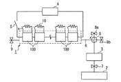
更に、図8は、本発明の燃料電池発電システムの他の例を示す概略図である。図8に示す燃料電池発電システムでは、開閉弁8bと水素除去装置3とを接続して循環経路11を構成し、循環経路11内が異常圧力となった場合にのみ、循環経路11内の水素が系外に排出できるよう逆流防止弁12を設けている以外は、図7に示す燃料電池発電システムと同様の構成である。   FIG. 8 is a schematic view showing another example of the fuel cell power generation system of the present invention. In the fuel cell power generation system shown in FIG. 8, the on-off valve 8b and the hydrogen removal device 3 are connected to form the circulation path 11, and only when the pressure in the circulation path 11 becomes abnormal pressure, the hydrogen in the circulation path 11 7 is the same configuration as that of the fuel cell power generation system shown in FIG. 7 except that a backflow prevention valve 12 is provided so that can be discharged out of the system.

図6および図7に示す燃料電池発電システムでは、開閉弁8bを通過した水素は系外に排出されるが、図8に示す燃料電池発電システムでは、循環経路11を経て水素除去装置3に再び送り込むことができる。そのため、系外へ排出される水素量を低減でき、水素除去効率をより高めることができる。   In the fuel cell power generation system shown in FIGS. 6 and 7, hydrogen that has passed through the on-off valve 8b is discharged out of the system, but in the fuel cell power generation system shown in FIG. Can be sent. Therefore, the amount of hydrogen discharged out of the system can be reduced, and the hydrogen removal efficiency can be further increased.

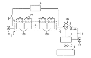
また、図9は、本発明の燃料電池発電システムの他の例を示す概略図である。図9に示す燃料電池発電システムは、図8に示す燃料電池発電システムの逆流防止弁9に代えて、流路切替え部13を設けた例である。流路切替え部13には、逆流防止弁14と開閉弁15とが接続されている。   FIG. 9 is a schematic view showing another example of the fuel cell power generation system of the present invention. The fuel cell power generation system shown in FIG. 9 is an example in which a flow path switching unit 13 is provided instead of the backflow prevention valve 9 of the fuel cell power generation system shown in FIG. A backflow prevention valve 14 and an on-off valve 15 are connected to the flow path switching unit 13.

図9の燃料電池発電システムでは、燃料電池1の作動時には、流路切替え部13は、燃料電池1側と逆流防止弁14側とで流路を形成するように設定され、燃料電池1内への外気の流入を逆流防止弁14で防止する。そして、燃料電池1の作動停止後には、流路切替え部13を矢印の方向に90度回転させ、開閉弁15を開いて、燃料電池1内へ外気を取り込むことができる。そのため、図9の燃料電池発電システムでは、例えば、図7や図8で示す構成の燃料電池発電システムよりも、燃料電池1内のガス置換をより迅速に行うことができる。   In the fuel cell power generation system of FIG. 9, when the fuel cell 1 is operated, the flow path switching unit 13 is set so as to form a flow path between the fuel cell 1 side and the backflow prevention valve 14 side. Inflow of outside air is prevented by the backflow prevention valve 14. After the operation of the fuel cell 1 is stopped, the flow path switching unit 13 can be rotated 90 degrees in the direction of the arrow to open the on-off valve 15 so that outside air can be taken into the fuel cell 1. Therefore, in the fuel cell power generation system of FIG. 9, for example, the gas replacement in the fuel cell 1 can be performed more quickly than the fuel cell power generation system having the configuration shown in FIGS.

流路切替え部は、図6〜図8に示すように1つだけ設けてもよく、図9に示すように複数設けてもよいし、また、図9の流路切替え部5を省略し、流路切替え部13のみを設けても構わない。しかし、燃料電池1の作動停止後に燃料電池1内への水素の侵入をより確実に遮断できる点で、流路切替え部は、少なくとも水素除去装置3と燃料電池1との間に設けることがより好ましい。また、流路切替え部5を作動させる条件は、図8、図9および後述する図10に示す構成の燃料電池発電システムにおいても、図6および図7に示す構成の燃料電池発電システムについて説明した条件と同条件とすることができる。   Only one flow path switching unit may be provided as shown in FIGS. 6 to 8, or a plurality of flow path switching units may be provided as shown in FIG. 9, or the flow path switching unit 5 in FIG. Only the flow path switching unit 13 may be provided. However, it is more preferable to provide the flow path switching unit at least between the hydrogen removal device 3 and the fuel cell 1 in that hydrogen can enter the fuel cell 1 more reliably after the operation of the fuel cell 1 is stopped. preferable. In addition, the conditions for operating the flow path switching unit 5 have been described for the fuel cell power generation system configured as shown in FIGS. 6 and 7 in the fuel cell power generation system configured as shown in FIGS. It can be the same condition as the condition.

また、図10は、本発明の燃料電池発電システムの他の例を示す概略図である。図10に示す燃料電池発電システムは、燃料電池1の作動停止後に、流路切替え部5、13から燃料電池1内に外気を取り込む際に、システム内の残留水素を強制的に排気可能とするためのブロア16、17を設置した例である。また、各MEA100には、逆流防止弁18が接続されている。   FIG. 10 is a schematic view showing another example of the fuel cell power generation system of the present invention. The fuel cell power generation system shown in FIG. 10 enables the residual hydrogen in the system to be forcibly exhausted when the outside air is taken into the fuel cell 1 from the flow path switching units 5 and 13 after the operation of the fuel cell 1 is stopped. This is an example in which blowers 16 and 17 are installed. Each MEA 100 is connected to a backflow prevention valve 18.

図10の燃料電池発電システムでは、燃料電池1の作動時にはブロア16、17は停止しておき、燃料電池1の作動停止後に、流路切替え部5、13を矢印の方向に90度回転させて流路を切替えると共に、ブロア16、17を駆動させて、流路内に強制的に外気を導入する。この際、ブロア16、17による外気の流入方向が、いずれも燃料電池1内に外気を導入する方向である場合、各MEA100に逆流防止弁18を設けた排気路を設けておくと、上記排気路を通じて僅かに残留した水素を燃料電池1外に排気することができる。   In the fuel cell power generation system of FIG. 10, the blowers 16 and 17 are stopped when the fuel cell 1 is operated, and after the operation of the fuel cell 1 is stopped, the flow path switching units 5 and 13 are rotated 90 degrees in the direction of the arrow. While switching the flow path, the blowers 16 and 17 are driven to forcibly introduce outside air into the flow path. At this time, when the inflow direction of the outside air by the blowers 16 and 17 is the direction in which the outside air is introduced into the fuel cell 1, if the exhaust passage provided with the backflow prevention valve 18 is provided in each MEA 100, Hydrogen remaining slightly through the passage can be exhausted out of the fuel cell 1.

一方、例えば、ブロア16を、外気をシステム内に取り込むように駆動させ、ブロア17を、システム内の気体をシステム外に排気するように駆動させて、燃料電池1内のガス置換を行うこともできる。この場合には、開閉弁8a、15によって、排気量などの調整が可能である。   On the other hand, for example, the blower 16 is driven so as to take outside air into the system, and the blower 17 is driven so as to exhaust the gas inside the system to the outside of the system, thereby replacing the gas in the fuel cell 1. it can. In this case, the exhaust amount and the like can be adjusted by the on-off valves 8a and 15.

このように、図10に示す構成の燃料電池発電システムでは、図6〜図9に示す構成の燃料電池発電システムよりも迅速に燃料電池1内のガス置換を行うことができる。   As described above, the fuel cell power generation system having the configuration shown in FIG. 10 can perform gas replacement in the fuel cell 1 more quickly than the fuel cell power generation system having the configuration shown in FIGS.

(実施形態3)
燃料電池内部の圧力変動に対応することができる本発明の実施形態のうち、実施形態2とは異なる実施形態の一例を以下に示す。
(Embodiment 3)
Of the embodiments of the present invention that can cope with pressure fluctuations inside the fuel cell, an example of an embodiment different from the second embodiment is shown below.

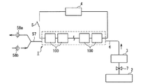
図11は、内部圧力調整部を設けた本発明の燃料電池発電システムの一例を示す概略図である。図11の燃料電池発電システムは、燃料電池1に内部圧力調整部を設けた以外は、図1に示される燃料電池発電システムと同様の構成を有する。   FIG. 11 is a schematic view showing an example of the fuel cell power generation system of the present invention provided with an internal pressure adjusting unit. The fuel cell power generation system of FIG. 11 has the same configuration as the fuel cell power generation system shown in FIG. 1 except that the fuel cell 1 is provided with an internal pressure adjustment unit.

図11に示す燃料電池発電システムは、燃料電池1内の燃料流路6と燃料電池1の外部とを通気経路57で繋いでいる。58aおよび58bは、内部圧力調整部としての逆流防止部であり、逆流防止部58aは、燃料電池1内のガス(水素)を燃料電池1の外部へ排気する方向のみに流路を開放でき、逆流防止部58bは、燃料電池1の外部から燃料電池1内に外気を取り込む方向のみに流路を開放できる。   In the fuel cell power generation system shown in FIG. 11, the fuel flow path 6 in the fuel cell 1 and the outside of the fuel cell 1 are connected by a ventilation path 57. 58a and 58b are backflow prevention units as internal pressure adjusting units, and the backflow prevention unit 58a can open the flow path only in the direction of exhausting the gas (hydrogen) in the fuel cell 1 to the outside of the fuel cell 1, The backflow prevention unit 58 b can open the flow path only in the direction in which outside air is taken into the fuel cell 1 from the outside of the fuel cell 1.

また、7はストップバルブで、燃料電池1の作動停止に合わせて閉じることで、水素製造装置2から燃料電池1への水素の供給を遮断し、また、燃料電池1の作動開始に合わせて開くことで、水素製造装置2から燃料電池1への水素の供給を可能とするためのものである。   A stop valve 7 is closed when the fuel cell 1 is stopped to shut off the supply of hydrogen from the hydrogen production device 2 to the fuel cell 1 and opens when the fuel cell 1 starts operating. Thus, hydrogen can be supplied from the hydrogen production apparatus 2 to the fuel cell 1.

水素除去装置3は、外部負荷4がオフになった時、すなわち、燃料電池1から外部負荷4への電力供給が停止した際に作動させる。これによって、水素製造装置2から燃料電池1への水素供給が継続してしまう場合や、ストップバルブ7によって水素供給を停止しても燃料電池1内へ余剰水素が流れ込んでしまう場合に、水素除去装置3により、燃料電池1へ向かう水素を除去することが可能となる。その結果、燃料電池1内への水素供給がなくなるか、または、その供給量が大幅に低減される。   The hydrogen removing device 3 is operated when the external load 4 is turned off, that is, when the power supply from the fuel cell 1 to the external load 4 is stopped. As a result, when hydrogen supply from the hydrogen production device 2 to the fuel cell 1 continues or when surplus hydrogen flows into the fuel cell 1 even if the hydrogen supply is stopped by the stop valve 7, hydrogen removal is performed. The device 3 makes it possible to remove hydrogen going to the fuel cell 1. As a result, the supply of hydrogen into the fuel cell 1 is lost or the supply amount is greatly reduced.

また、水素製造装置2から供給される余剰水素の量よりも、水素除去装置3の水素除去の能力が高い場合は、水素製造装置2からの水素だけでなく、燃料電池1の内部に残存する余剰水素も除去することができる。   Further, when the hydrogen removal capability of the hydrogen removal device 3 is higher than the amount of surplus hydrogen supplied from the hydrogen production device 2, not only the hydrogen from the hydrogen production device 2 but also the fuel cell 1 remains. Excess hydrogen can also be removed.

水素除去装置3は、燃料電池1の作動中に作動させることもできる。例えば、水素供給量が、燃料電池1での発電に必要とされる水素の量を超える場合に、水素除去装置3を作動させて余剰の水素を除去し、燃料電池1への水素供給量を調整することもできる。   The hydrogen removing device 3 can also be operated during the operation of the fuel cell 1. For example, when the hydrogen supply amount exceeds the amount of hydrogen required for power generation in the fuel cell 1, the hydrogen removal device 3 is operated to remove excess hydrogen, and the hydrogen supply amount to the fuel cell 1 is increased. It can also be adjusted.

また、水素製造装置2から燃料電池1への水素供給量の変動などにより、燃料電池1の内部の圧力が高くなり過ぎた場合には、逆流防止部58aが作動して燃料電池1内のガスを燃料電池1外へ排出することができる。   Further, when the internal pressure of the fuel cell 1 becomes too high due to fluctuations in the amount of hydrogen supplied from the hydrogen production device 2 to the fuel cell 1, the backflow prevention unit 58a is activated and the gas in the fuel cell 1 is activated. Can be discharged out of the fuel cell 1.

一方、水素除去装置3による水素消費などにより、燃料電池1の内部の圧力が低くなり過ぎた場合には、逆流防止部58bにより、燃料電池1内に外気を素早く取入れることができる。これらの作用によって、燃料電池1の内部の圧力変動による燃料電池1の破損を防ぎ、燃料電池1の出力を安定に保つことができる。   On the other hand, when the internal pressure of the fuel cell 1 becomes too low due to hydrogen consumption by the hydrogen removing device 3 or the like, outside air can be quickly taken into the fuel cell 1 by the backflow prevention unit 58b. By these actions, the fuel cell 1 can be prevented from being damaged due to pressure fluctuations inside the fuel cell 1, and the output of the fuel cell 1 can be kept stable.

本発明の燃料電池発電システムでは、逆流防止部58aおよび58bは、いずれか一方のみ備えていてもよいが、両者を設置していることが好ましい。   In the fuel cell power generation system of the present invention, the backflow prevention units 58a and 58b may be provided with either one, but it is preferable that both are installed.

本発明の燃料電池発電システムに用い得る逆流防止部としては、気密性を有するものであって一方向の通気孔機能を有するものであれば特に限定されないが、平行移動する弁体を有するリフト型逆止弁、蝶番運動をする弁体を有するスイング型逆止弁、球状の弁体を有するボール弁などの方向逆止弁;減圧弁、安全弁、逃がし弁(チェックバルブ)などの、一定の圧力変動以上で自然に弁によるガスが排出される構造を有する圧力制御弁;などが好適に用いられる。また、上記例示の弁を電気的に駆動可能な電磁弁とすることで、燃料電池からのガスの排気や燃料電池内への外気の取り込みを電気的に制御することもできる。   The backflow prevention unit that can be used in the fuel cell power generation system of the present invention is not particularly limited as long as it has airtightness and has a one-way vent hole function, but is a lift type having a valve body that moves in parallel. Directional check valves such as check valves, swing-type check valves with hinged valve bodies, ball valves with spherical valve bodies; constant pressures such as pressure reducing valves, safety valves, and relief valves (check valves) A pressure control valve having a structure in which gas from the valve is naturally discharged at a fluctuation or more is preferably used. Further, by making the above illustrated valve an electromagnetic valve that can be electrically driven, the exhaust of gas from the fuel cell and the intake of outside air into the fuel cell can be electrically controlled.

逆流防止部における開放開始作動圧力の好適値は、燃料電池発電システムの大きさなどによって変動し得るが、例えば、ゲージ圧で1.0MPa以下であることが好ましい。また、燃料電池発電システムが、燃料電池1内の燃料流路から燃料電池1の外部へ排気する方向のみに流路を開放する逆流防止部58aと、燃料電池1の外部から燃料電池1の内部の燃料流路に外気が流入する方向のみに流路を開放する逆流防止部58bの両者を備えている場合における、逆流防止部58aおよび58bの開放開始作動圧力の差圧値の好適値も、燃料電池発電システムの大きさによって変動し得るが、0〜0.5MPaであることが好ましい。逆流防止部58aおよび58bの開放開始作動圧力に差を付ける場合には、燃料電池1の作動中に燃料電池1内に外気が取り込まれることによる出力低下を防止するため、逆流防止部58bの開放開始作動圧力を、逆流防止部58aの開放開始作動圧力よりも高くすることが好ましい。   A suitable value for the opening start operating pressure in the backflow prevention unit may vary depending on the size of the fuel cell power generation system, but is preferably, for example, 1.0 MPa or less in terms of gauge pressure. Further, the fuel cell power generation system opens the flow path only in the direction of exhausting from the fuel flow path in the fuel cell 1 to the outside of the fuel cell 1, and the inside of the fuel cell 1 from the outside of the fuel cell 1. The preferred value of the differential pressure value of the opening start working pressure of the backflow prevention portions 58a and 58b in the case where both of the backflow prevention portions 58b that open the flow passage only in the direction in which the outside air flows into the fuel flow passage is provided. Although it may vary depending on the size of the fuel cell power generation system, it is preferably 0 to 0.5 MPa. When making a difference between the opening start operating pressures of the backflow prevention units 58a and 58b, the backflow prevention unit 58b is opened in order to prevent a decrease in output due to outside air being taken into the fuel cell 1 during operation of the fuel cell 1. The starting operating pressure is preferably higher than the opening starting operating pressure of the backflow prevention unit 58a.

逆流防止部の構成材料としては、気密性と耐腐食性とを有するものであれば特に限定されないが、例えば、ポリテトラフルオロエチレン(PTFE)、エチレン−テトラフルオロエチレン共重合体(E/TFE)、テトラフルオロエチレン−ヘキサフルオロプロピレン共重合体(FEP)、テトラフルオロエチレン−パーフルオロアルキルビニルエーテル共重合体(PFA)などの耐熱性フッ素樹脂;ポリプロピレン(PP)、ポリアセタール樹脂;などが好適である。   The constituent material of the backflow prevention part is not particularly limited as long as it has airtightness and corrosion resistance. For example, polytetrafluoroethylene (PTFE), ethylene-tetrafluoroethylene copolymer (E / TFE) Heat-resistant fluororesins such as tetrafluoroethylene-hexafluoropropylene copolymer (FEP) and tetrafluoroethylene-perfluoroalkyl vinyl ether copolymer (PFA); polypropylene (PP), polyacetal resin;

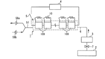
また、図12は、本発明の燃料電池発電システムの他の例を示す概略図である。図12の燃料電池発電システムは、図11に示される燃料電池発電システムの燃料電池1に備えられた個々のMEA100に、リード体などにより抵抗10を接続した例を示している。各MEA100の正極と負極とは、抵抗10を介して電気的に導通させることができる。図12の燃料電池発電システムにおける各構成要素の作動条件などは、図2あるいは図11に示される燃料電池発電システムと同様の設定とすることができる。   FIG. 12 is a schematic view showing another example of the fuel cell power generation system of the present invention. The fuel cell power generation system of FIG. 12 shows an example in which a resistor 10 is connected to each MEA 100 provided in the fuel cell 1 of the fuel cell power generation system shown in FIG. The positive electrode and the negative electrode of each MEA 100 can be electrically connected via the resistor 10. The operating conditions of each component in the fuel cell power generation system of FIG. 12 can be set to the same settings as those of the fuel cell power generation system shown in FIG. 2 or FIG.

図12の燃料電池発電システムでは、外部負荷4をオフにし、個々のMEA100において、正極−負極間を繋ぐリード体に設けたスイッチ(s)をオンにして燃料電池1内の残留水素を消費すると、燃料電池1内の圧力が低下する。この場合、逆流防止部58bが自動的に開放され、燃料電池1内に外気を取り込んで内圧の低下を防止する。このため、燃料電池1の破損を防ぐことができる。   In the fuel cell power generation system of FIG. 12, when the external load 4 is turned off and the switch (s) provided on the lead body connecting between the positive electrode and the negative electrode is turned on in each MEA 100, residual hydrogen in the fuel cell 1 is consumed. The pressure in the fuel cell 1 decreases. In this case, the backflow prevention unit 58b is automatically opened, and outside air is taken into the fuel cell 1 to prevent a decrease in internal pressure. For this reason, damage to the fuel cell 1 can be prevented.

図11や図12に示す燃料電池発電システムのように、通気経路57をT字状に分岐させる場合には、逆流防止部58aによって燃料電池1内の燃料流路6から燃料電池1の外部へ水素などを排気する際に、燃料電池1内で発生した水などが通気経路57内に侵入して逆流防止部58bの機能を低下させることもある。このような場合には、逆流防止部58aに接続する通気経路と、逆流防止部58bに接続する通気経路とを、後述する図13のように、別々に設ければよい。   When the ventilation path 57 is branched in a T-shape as in the fuel cell power generation system shown in FIGS. 11 and 12, the backflow prevention unit 58a causes the fuel flow path 6 in the fuel cell 1 to go outside the fuel cell 1. When exhausting hydrogen or the like, water or the like generated in the fuel cell 1 may enter the ventilation path 57 and reduce the function of the backflow prevention unit 58b. In such a case, the ventilation path connected to the backflow prevention unit 58a and the ventilation path connected to the backflow prevention unit 58b may be provided separately as shown in FIG.

また、本発明の燃料電池発電システムには、逆流防止部58aおよび58bのいずれか一方あるいは両方を複数個設けてもよい。   Further, the fuel cell power generation system of the present invention may be provided with a plurality of either one or both of the backflow prevention units 58a and 58b.

図13は、本発明の燃料電池発電システムの他の例を示す概略図である。図13に示す燃料電池発電システムでは、別々の通気経路57a、57bを備え、逆流防止部58aのガス放出側で、通気経路57aはT字状に分岐している。分岐した通気経路57aの一端には、通気経路57a側から外部に排気する方向のみに流路を開放する逆流防止部58cが設置されており、他の一端は水素除去装置3と接続され循環経路60を形成している。循環経路60には、水素除去装置3に流入する方向にのみ流路を開放する逆流防止部58dが設置されている。図13の燃料電池発電システムでは、燃料電池1の通気経路57aから逆流防止部58aを経て排出された余剰のガスを、循環経路60を経由し、逆流防止部58dを経て水素除去装置3に導入することができる。そのため、燃料電池1から通気経路57aを経て燃料電池1外に排出される水素の量を減らすことが可能であり、水素除去効率をより高めることができる。   FIG. 13 is a schematic view showing another example of the fuel cell power generation system of the present invention. The fuel cell power generation system shown in FIG. 13 includes separate ventilation paths 57a and 57b, and the ventilation path 57a branches in a T-shape on the gas discharge side of the backflow prevention unit 58a. One end of the branched ventilation path 57a is provided with a backflow prevention portion 58c that opens the flow path only in the direction of exhausting from the ventilation path 57a side to the outside, and the other end is connected to the hydrogen removal device 3 and connected to the circulation path. 60 is formed. The circulation path 60 is provided with a backflow prevention unit 58d that opens the flow path only in the direction of flowing into the hydrogen removal device 3. In the fuel cell power generation system of FIG. 13, surplus gas discharged from the ventilation path 57a of the fuel cell 1 through the backflow prevention unit 58a is introduced into the hydrogen removal apparatus 3 through the circulation path 60 and through the backflow prevention unit 58d. can do. Therefore, it is possible to reduce the amount of hydrogen discharged from the fuel cell 1 to the outside of the fuel cell 1 through the ventilation path 57a, and the hydrogen removal efficiency can be further increased.

図13の燃料電池発電システムでは、システムの大きさによって、逆流防止部58a、58c、58dの開放開始作動圧力の差圧値の好適な範囲が変動し得るが、逆流防止部58aと逆流防止部58cとの差圧値、逆流防止部58aと逆流防止部58dとの差圧値、逆流防止部58cと逆流防止部58dとの差圧値のいずれについても、0〜0.5MPaであることが好ましい。また、逆流防止部58a、58c、58dの開放開始作動圧力に差を付ける場合には、開放開始作動圧力の大きさの関係が、58c>58a>58dであることが好ましい。   In the fuel cell power generation system of FIG. 13, the preferred range of the differential pressure value of the opening start operating pressure of the backflow prevention units 58a, 58c, 58d can vary depending on the size of the system, but the backflow prevention unit 58a and the backflow prevention unit The differential pressure value with respect to 58c, the differential pressure value between the backflow prevention portion 58a and the backflow prevention portion 58d, and the differential pressure value between the backflow prevention portion 58c and the backflow prevention portion 58d are all 0 to 0.5 MPa. preferable. Moreover, when making a difference in the opening start operation pressure of the backflow prevention parts 58a, 58c, 58d, it is preferable that the relationship of the magnitude of the opening start operation pressure is 58c> 58a> 58d.

これまで図1〜図13を用いて本発明を説明したが、図1〜図13は、本発明の一例を示したものに過ぎず、本発明の燃料電池発電システムは、図1〜図13に示すものに限定される訳ではない。   Although the present invention has been described above with reference to FIGS. 1 to 13, FIGS. 1 to 13 are merely examples of the present invention, and the fuel cell power generation system of the present invention is illustrated in FIGS. 1 to 13. It is not necessarily limited to what is shown in the above.

以下、実施例に基づいて本発明を詳細に述べる。   Hereinafter, the present invention will be described in detail based on examples.

(実施例1)
<燃料電池の作製>
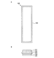
まず、図3に示す構造の燃料電池を作製した。第1のMEA100には、図14A、Bに示す構成のものを用いた。図14AはMEA100の平面図、図14BはMEA100の断面図であり、図14Bでは各構成要素の理解を容易にするために、断面であることを示す斜線を省略している。MEA100の正極および負極には、カーボンクロス上にPt担持カーボンを塗布した電極(E−TEK社製「LT140E−W」、Pt量:0.5mg/cm2)を用いた。また、固体電解質膜103には、デュポン社製の「ナフィオン112」を用いた。各電極の大きさは25mm×92mm、固体電解質膜の大きさは29mm×96mmとした。
Example 1
<Fabrication of fuel cell>
First, a fuel cell having the structure shown in FIG. 3 was produced. As the first MEA 100, the one shown in FIGS. 14A and 14B was used. 14A is a plan view of the MEA 100, and FIG. 14B is a cross-sectional view of the MEA 100. In FIG. 14B, in order to facilitate understanding of each component, a hatched line indicating a cross section is omitted. For the positive electrode and the negative electrode of MEA100, electrodes (“LT140E-W” manufactured by E-TEK, Pt amount: 0.5 mg / cm 2 ) coated with Pt-supported carbon on carbon cloth were used. For the solid electrolyte membrane 103, “Nafion 112” manufactured by DuPont was used. The size of each electrode was 25 mm × 92 mm, and the size of the solid electrolyte membrane was 29 mm × 96 mm.

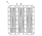
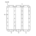
燃料電池1の作製に用いた正極パネルプレート20の平面図を図15に示す。正極パネルプレート20には、ステンレス鋼(SUS304)製で厚みが2mmのものを用いた。図15において、30aは酸素導入孔であり、図3において正極開口部30を形成する。53は、正極パネルプレート20と負極パネルプレート21とをボルト32とナット33で固定するためのネジ穴である。正極パネルプレート20には、各MEA100の正極拡散層101と対応するように、酸素導入孔30aとして、1×13mmの長方形型の穴を、各々上下に6個、左右に12個、合計72個を1セットとして、合計3セット配置した。負極パネルプレート21も正極パネルプレート20と同様の材質、形状とした。すなわち、パネルプレートにおける開口は、正極では正極開口部30を形成する酸素導入孔となり、負極では負極開口部31を形成する燃料導入孔となる。   FIG. 15 is a plan view of the positive electrode panel plate 20 used for manufacturing the fuel cell 1. The positive electrode panel plate 20 was made of stainless steel (SUS304) and had a thickness of 2 mm. In FIG. 15, reference numeral 30a denotes an oxygen introduction hole, which forms the positive electrode opening 30 in FIG. Reference numeral 53 denotes a screw hole for fixing the positive panel plate 20 and the negative panel plate 21 with bolts 32 and nuts 33. The positive electrode panel plate 20 has a total of 72 1 × 13 mm rectangular holes as the oxygen introduction holes 30a, each corresponding to the positive electrode diffusion layer 101 of each MEA 100, 6 vertically and 12 horizontally. A total of 3 sets were arranged. The negative electrode panel plate 21 was also made of the same material and shape as the positive electrode panel plate 20. That is, the opening in the panel plate is an oxygen introduction hole that forms the positive electrode opening 30 in the positive electrode, and a fuel introduction hole that forms the negative electrode opening 31 in the negative electrode.

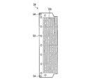
また、燃料電池1の作製に用いた正極集電プレート(正極端部集電プレート)24の平面図を図16に、正極集電プレート25a、25bの平面図を図17に示す。図16および図17において、30bは酸素導入孔であり、図3において正極開口部30を形成する。また、図16に示す正極端部集電プレート24には、正極集電端子部54が設けられており、図17に示す正極集電プレート25a、25bには正極直列接続タブ55がそれぞれ2つ設けられている。   Further, FIG. 16 shows a plan view of the positive electrode current collecting plate (positive electrode end current collecting plate) 24 used for manufacturing the fuel cell 1, and FIG. 17 shows a plan view of the positive electrode current collecting plates 25a and 25b. 16 and 17, reference numeral 30b denotes an oxygen introduction hole, which forms the positive electrode opening 30 in FIG. Moreover, the positive electrode end current collecting plate 24 shown in FIG. 16 is provided with a positive electrode current collecting terminal portion 54, and the positive electrode current collecting plates 25a and 25b shown in FIG. Is provided.

正極集電プレート24、25a、25bには、ニッケルに金メッキを施した厚み0.3mmのものを用い、酸素導入孔30bおよびネジ穴53の形状および配置は、正極パネルプレート20における酸素導入孔およびネジ穴と同様とした。また、負極端部集電プレート26は正極端部集電プレート24と同様の材質、形状とし、負極集電プレート27a、27bは正極集電プレート25a、25bと同様の材質、形状とした。すなわち、集電プレートにおける開口は、正極では正極開口部30を形成する酸素導入孔となり、負極では負極開口部31を形成する燃料導入孔となる。   The positive electrode current collecting plates 24, 25a and 25b are made of nickel with a gold plating thickness of 0.3 mm. The shape and arrangement of the oxygen introduction hole 30b and the screw hole 53 are the same as the oxygen introduction hole in the positive electrode panel plate 20 and Same as screw hole. Further, the negative electrode end current collecting plate 26 has the same material and shape as the positive electrode end current collecting plate 24, and the negative electrode current collecting plates 27a and 27b have the same material and shape as the positive electrode current collecting plates 25a and 25b. That is, the opening in the current collector plate is an oxygen introduction hole that forms the positive electrode opening 30 in the positive electrode, and a fuel introduction hole that forms the negative electrode opening 31 in the negative electrode.

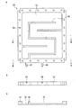
燃料電池1の作製に用いた正極絶縁プレート22を図18A、Bに示す。図18Aは正極絶縁プレート22の平面図である。また、図18Bは図18AのI−I線断面図であるが、ネジ穴53の配置を点線で示しており、この配置の理解を容易にするために、断面であることを示す斜線を省略している。正極絶縁プレート22は、金属製の正極パネルプレート20と、正極集電プレート24、25a、25bとの間に配置され、これらのプレート間を絶縁するためのものである。図18A、Bにおいて、66は正極集電プレート24、25a、25bを収めるための凹部である。   18A and 18B show a positive electrode insulating plate 22 used for manufacturing the fuel cell 1. FIG. 18A is a plan view of the positive electrode insulating plate 22. 18B is a cross-sectional view taken along the line II of FIG. 18A, and the arrangement of the screw holes 53 is indicated by a dotted line, and in order to facilitate understanding of this arrangement, the hatched lines indicating the cross section are omitted. is doing. The positive electrode insulating plate 22 is disposed between the metal positive electrode panel plate 20 and the positive electrode current collecting plates 24, 25a, 25b, and insulates these plates. In FIGS. 18A and 18B, reference numeral 66 denotes a recess for accommodating the positive electrode current collecting plates 24, 25a, and 25b.

正極絶縁プレート22には、ガラスエポキシ樹脂製で厚みが0.5mmのものを用いた。酸素導入孔30cおよびネジ穴53の形状および配置は、正極パネルプレート20における酸素導入孔およびネジ穴と同様とした。また、負極絶縁プレート23は正極絶縁プレート22と同様の材質、形状とした。すなわち、絶縁プレートにおける開口は、正極では正極開口部30を形成する酸素導入孔となり、負極では負極開口部31を形成する燃料導入孔となる。   A positive electrode insulating plate 22 made of glass epoxy resin and having a thickness of 0.5 mm was used. The shape and arrangement of the oxygen introduction hole 30 c and the screw hole 53 were the same as the oxygen introduction hole and the screw hole in the positive electrode panel plate 20. The negative electrode insulating plate 23 was made of the same material and shape as the positive electrode insulating plate 22. That is, the opening in the insulating plate is an oxygen introduction hole that forms the positive electrode opening 30 in the positive electrode, and a fuel introduction hole that forms the negative electrode opening 31 in the negative electrode.

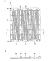
燃料電池1の作製に用いた燃料タンク部29を図19A、B、Cに示す。図19Aは燃料タンク部29の平面図である。また、図19Bは図19AのII−II線断面図、図19Cは図19AのIII−III線断面図であるが、これらの断面図ではネジ穴53の配置を点線で示していることから、この配置の理解を容易にするために、断面であることを示す斜線を省略している。   19A, 19B and 19C show the fuel tank portion 29 used for manufacturing the fuel cell 1. FIG. FIG. 19A is a plan view of the fuel tank portion 29. 19B is a cross-sectional view taken along the line II-II of FIG. 19A, and FIG. 19C is a cross-sectional view taken along the line III-III of FIG. 19A. In these cross-sectional views, the arrangement of the screw holes 53 is indicated by dotted lines. In order to facilitate understanding of this arrangement, the hatched lines indicating the cross section are omitted.

燃料タンク部29は、燃料をMEA100の負極へ供給したり、燃料を保持するために設けるものであり、燃料を供給するための燃料供給口67と、燃料を排出するための燃料排出口68を設けており、さらに、燃料の供給が各MEA100に均一に行われるように、燃料流通ガイド部69を設けている。燃料は、タンク内部70に保持される。   The fuel tank unit 29 is provided to supply fuel to the negative electrode of the MEA 100 or hold the fuel. The fuel tank unit 29 includes a fuel supply port 67 for supplying fuel and a fuel discharge port 68 for discharging fuel. Furthermore, a fuel flow guide unit 69 is provided so that the fuel is supplied uniformly to each MEA 100. The fuel is held in the tank interior 70.

燃料タンク部29には、ガラスエポキシ樹脂製で厚み3mmのものを用いた。中央のタンク内部70の深さは2mmとした。   The fuel tank 29 is made of glass epoxy resin and has a thickness of 3 mm. The depth of the central tank interior 70 was 2 mm.

燃料電池1の作製に用いたシール材28a、28bの平面図を図20に示す。シール材28a、28bは、MEA100の上下に配置するものであり、その際、MEA100の電極はシール材28a、28bに設けた孔72に収まり、固体電解質膜103のうち電極部分からはみ出た部分は、シール材28a、28bに挟まれる。このような構成とすることで、燃料と空気中の酸素とを隔離して、燃料電池1を良好に機能させることが可能となる。シール材28a、28bには直列接続タブ接触エリア71を設けてあり、この部分で正極集電プレートの正極直列接続タブと負極集電プレートの負極直列接続タブとを電気的に接触させ、各MEA100を直列に接続する。   FIG. 20 is a plan view of the sealing materials 28a and 28b used for manufacturing the fuel cell 1. FIG. The sealing materials 28a and 28b are arranged above and below the MEA 100. At that time, the electrodes of the MEA 100 are accommodated in the holes 72 provided in the sealing materials 28a and 28b, and the portion of the solid electrolyte membrane 103 that protrudes from the electrode portion is Between the sealing materials 28a and 28b. With such a configuration, the fuel cell 1 can be satisfactorily functioned by separating the fuel and oxygen in the air. A series connection tab contact area 71 is provided in the sealing materials 28a and 28b. In this portion, the positive electrode series connection tab of the positive electrode current collector plate and the negative electrode series connection tab of the negative electrode current collector plate are electrically contacted, and each MEA 100 Are connected in series.

シール材28a、28bには、シリコンゴム製で厚み0.2mmのものを用い、MEA100の電極を収めるための孔72の大きさは26mm×93mmとした。   The sealing materials 28a and 28b were made of silicon rubber and had a thickness of 0.2 mm, and the size of the hole 72 for accommodating the electrode of the MEA 100 was 26 mm × 93 mm.

以上の各部材を図3に示す順序で積層し、ボルト32とナット33を用いて一体化し、MEA100を3個直列に接続して燃料電池1を作製した。また、各MEA100には、正極および負極にリード体を取り付け、10Ωの抵抗およびスイッチをこれらのリード体に接続して、正極−負極間を導通可能とした。   The above members were stacked in the order shown in FIG. 3 and integrated using bolts 32 and nuts 33, and three MEAs 100 were connected in series to produce the fuel cell 1. In each MEA 100, lead bodies were attached to the positive electrode and the negative electrode, and a 10 Ω resistor and a switch were connected to these lead bodies to enable conduction between the positive electrode and the negative electrode.

<水素除去装置の作製>
次に、図5に示す構造の水素除去装置3を作製した。第2のMEA200には、図21A、Bに示す構成のものを用いた。図21AはMEA200の平面図、図21BはMEA200の断面図であり、図21Bでは各構成要素の理解を容易にするために、断面であることを示す斜線を省略している。MEA200の正極、負極および固体電解質膜には、燃料電池1の第1のMEA100における正極、負極および固体電解質膜と同じものを用いた。各電極の大きさは30mm×60mm、固体電解質膜の大きさは34mm×64mmとした。
<Production of hydrogen removal device>
Next, the hydrogen removal apparatus 3 having the structure shown in FIG. 5 was produced. A second MEA 200 having the configuration shown in FIGS. 21A and 21B was used. FIG. 21A is a plan view of the MEA 200, and FIG. 21B is a cross-sectional view of the MEA 200. In FIG. 21B, in order to facilitate understanding of each component, a hatched line indicating a cross section is omitted. As the positive electrode, the negative electrode, and the solid electrolyte membrane of the MEA 200, the same materials as the positive electrode, the negative electrode, and the solid electrolyte membrane of the first MEA 100 of the fuel cell 1 were used. The size of each electrode was 30 mm × 60 mm, and the size of the solid electrolyte membrane was 34 mm × 64 mm.

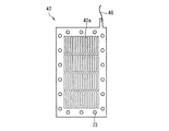
水素除去装置3の作製に用いた正極集電板42の平面図を図22に示す。図22において、73は、水素除去装置3の正極集電板42、負極集電板43およびタンク部45をボルト50とナット51で固定するためのネジ穴である。また、正極集電板42の端部には、正極リード線46が接続されている。   FIG. 22 shows a plan view of the positive electrode current collector plate 42 used for the production of the hydrogen removal device 3. In FIG. 22, reference numeral 73 denotes a screw hole for fixing the positive electrode current collector plate 42, the negative electrode current collector plate 43, and the tank portion 45 of the hydrogen removing device 3 with bolts 50 and nuts 51. A positive electrode lead wire 46 is connected to the end of the positive electrode current collector plate 42.

正極集電板42には、ニッケルに金メッキを施した厚み2mmのものを用いた。正極集電板42には、MEA200の正極拡散層201と対応するように、空気孔42aとして、1×13mmの長方形型の穴を、各々上下に4個、左右に15個、合計60個配置した。負極集電板43も正極集電板42と同様の形状、材質とした。すなわち、集電板における開口は、正極では空気孔42aとなり、負極では、図5に示される水素導入孔43aとなる。   As the positive electrode current collector plate 42, a nickel collector with a thickness of 2 mm obtained by gold plating was used. In the positive electrode current collector plate 42, four rectangular holes of 1 × 13 mm are arranged as the air holes 42 a in a vertical direction and 15 in the left and right directions, respectively, so as to correspond to the positive electrode diffusion layer 201 of the MEA 200. did. The negative electrode current collector plate 43 also has the same shape and material as the positive electrode current collector plate 42. That is, the opening in the current collector plate becomes the air hole 42a in the positive electrode and the hydrogen introduction hole 43a shown in FIG. 5 in the negative electrode.

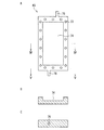
水素除去装置3の作製に用いたタンク部45を図23A、B、Cに示す。図23Aはタンク部45の平面図、図23Bは図23AのIV−IV線断面図、図23Cは図23AのV−V線断面図である。タンク部45は、水素製造装置2から水素除去装置3に流入する水素を保持し、MEA200の負極へ上記水素を供給するために設けるものであり、水素を供給するための水素供給口75と、水素を排出するための水素排出口76を備えている。水素は、タンク内部74に保持される。図23Aにおいて、73はネジ穴である。   The tank part 45 used for production of the hydrogen removal apparatus 3 is shown in FIGS. 23A is a plan view of the tank portion 45, FIG. 23B is a sectional view taken along line IV-IV in FIG. 23A, and FIG. 23C is a sectional view taken along line VV in FIG. The tank unit 45 holds hydrogen flowing from the hydrogen production device 2 to the hydrogen removal device 3, and is provided to supply the hydrogen to the negative electrode of the MEA 200. A hydrogen supply port 75 for supplying hydrogen, A hydrogen discharge port 76 for discharging hydrogen is provided. Hydrogen is held in the tank interior 74. In FIG. 23A, 73 is a screw hole.

タンク部45には、ガラスエポキシ樹脂製で厚み3mmのものを用いた。中央のタンク内部74の深さは2mmである。   The tank portion 45 made of glass epoxy resin and having a thickness of 3 mm was used. The depth of the central tank interior 74 is 2 mm.

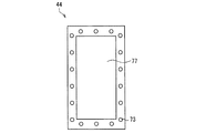
水素除去装置3の作製に用いたシール材44の平面図を図24に示す。シール材44は、シリコンゴム製で厚みが0.2mmであり、MEA200の電極を収めるため、31mm×61mmの大きさの孔77が形成されている。図24において、73はネジ穴である。   FIG. 24 shows a plan view of the sealing material 44 used for manufacturing the hydrogen removal apparatus 3. The sealing material 44 is made of silicon rubber and has a thickness of 0.2 mm, and a hole 77 having a size of 31 mm × 61 mm is formed to accommodate the electrode of the MEA 200. In FIG. 24, reference numeral 73 denotes a screw hole.

以上の各部材を図5に示す順序で積層し、ボルト50とナット51を用いて一体化した。さらに、正極集電板42および負極集電板43に、それぞれ、正極リード線46および負極リード線47を取り付け、20mΩの抵抗48およびスイッチ49をこれらのリード線に接続して、MEA200の正極−負極間を導通可能とした。   The above members were stacked in the order shown in FIG. 5 and integrated using bolts 50 and nuts 51. Further, a positive electrode lead wire 46 and a negative electrode lead wire 47 are attached to the positive electrode current collector plate 42 and the negative electrode current collector plate 43, respectively, and a 20 mΩ resistor 48 and a switch 49 are connected to these lead wires, so that the positive electrode − The conduction between the negative electrodes was made possible.

<水素製造装置の作製>
次に、図4に示す構成の水素供給源である水素製造装置2を作製した。水素発生物質収容容器34には、内容積50cm3のポリプロピレン製の角柱状の容器を用いた。水供給パイプ38、水素導出パイプ39、40、および水回収パイプ41には、内径2mm、外径3mmのポリプロピレン製のパイプを用いた。水素発生物質収容容器34に、水素発生物質である平均粒径3μmのアルミニウム粉末19.7gと、発熱物質である酸化カルシウム2.5gの混合物を入れた。水収容容器35には、内容積50cm3のポリプロピレン製の角柱状の容器を用い、その中に水を45g入れた。凝縮水分離器37には、内容積30cm3のポリプロピレン製の角柱状の容器を用いた。
<Production of hydrogen production equipment>
Next, a hydrogen production apparatus 2 as a hydrogen supply source having the configuration shown in FIG. 4 was produced. As the hydrogen generating substance storage container 34, a prismatic container made of polypropylene having an internal volume of 50 cm 3 was used. Polypropylene pipes having an inner diameter of 2 mm and an outer diameter of 3 mm were used for the water supply pipe 38, the hydrogen outlet pipes 39 and 40, and the water recovery pipe 41. A mixture of 19.7 g of aluminum powder having an average particle diameter of 3 μm, which is a hydrogen generating substance, and 2.5 g of calcium oxide, which is a heat generating substance, was placed in the hydrogen generating substance storage container 34. As the water container 35, a polypropylene prismatic container having an internal volume of 50 cm 3 was used, and 45 g of water was put therein. As the condensate separator 37, a polypropylene prismatic container having an internal volume of 30 cm 3 was used.

<燃料電池発電システムの組み立て>
以上の燃料電池1、水素製造装置2および水素除去装置3を用いて、図25に示す構成の燃料電池発電システムを組み立てた。図25に示す燃料電池発電システムは、3つのMEA100を用い、ストップバルブ7を設置しなかった以外は、図2に示す燃料電池発電システムと同様の構成である。燃料電池1と水素除去装置3との間を連結する水素供給パイプ(図5における水素供給パプ40b)には、内径2mm、外径3mmのポリプロピレン製のパイプを用いた。
<Assembly of fuel cell power generation system>
A fuel cell power generation system having the configuration shown in FIG. 25 was assembled using the fuel cell 1, the hydrogen production device 2, and the hydrogen removal device 3 described above. The fuel cell power generation system shown in FIG. 25 has the same configuration as the fuel cell power generation system shown in FIG. 2 except that three MEAs 100 are used and the stop valve 7 is not installed. The hydrogen feed pipe for connecting the fuel cell 1 and a hydrogen removing apparatus 3 (the hydrogen supply path b-flop 40b in FIG. 5), an inner diameter of 2 mm, was used polypropylene pipe having an outer diameter of 3 mm.

<発電試験>
上記燃料電池発電システムを用いて、25℃で発電試験を行った。水素製造装置2の水供給ポンプ36により、水収容容器35内の水35aを水素発生物質収容容器34へ供給して水素を発生させ、燃料電池1に水素を供給した。外部負荷4により、2.0Vの定電圧で燃料電池1を作動させ、4時間発電を行った。発電終了後に、外部負荷4を切断し、さらに水供給ポンプ36による水供給を停止し、同時に水素除去装置3のスイッチ49をオンにした。また、各MEA100に設けたスイッチ(s)も同時にオンにし、MEA100の正極と負極を電気的に導通させた。翌日、水素発生物質収容容器34および水収容容器35を取り外し、新たに水素発生物質および水を各容器に同量再投入し、上記と同じ条件で再び発電を開始した。この試験を毎日繰り返し実施した。
<Power generation test>
A power generation test was conducted at 25 ° C. using the fuel cell power generation system. The water 35 a in the water container 35 was supplied to the hydrogen generating substance container 34 by the water supply pump 36 of the hydrogen production apparatus 2 to generate hydrogen, and hydrogen was supplied to the fuel cell 1. The fuel cell 1 was operated at a constant voltage of 2.0 V by the external load 4 to generate power for 4 hours. After the power generation was completed, the external load 4 was disconnected, the water supply by the water supply pump 36 was stopped, and at the same time the switch 49 of the hydrogen removal device 3 was turned on. Moreover, the switch (s) provided in each MEA 100 was also turned on at the same time, and the positive electrode and the negative electrode of the MEA 100 were electrically connected. On the next day, the hydrogen generating substance storage container 34 and the water storage container 35 were removed, and the same amount of hydrogen generating substance and water were reintroduced into each container, and power generation was started again under the same conditions as described above. This test was repeated daily.

(比較例1)
水素除去装置3を設置しなかった以外は、実施例1と同様にして燃料電池発電システムを作製し、実施例1と同条件で発電試験を繰り返し実施した。
(Comparative Example 1)
A fuel cell power generation system was produced in the same manner as in Example 1 except that the hydrogen removal device 3 was not installed, and the power generation test was repeatedly performed under the same conditions as in Example 1.

実施例1および比較例1の燃料電池発電システムについて、1回目の発電試験の発電出力を基準にして、発電出力が1回目の発電出力の80%に低下するまでに繰り返すことのできる発電試験の回数を測定した。その結果を表1に示す。   Regarding the fuel cell power generation system of Example 1 and Comparative Example 1, a power generation test that can be repeated until the power generation output is reduced to 80% of the first power generation output based on the power generation output of the first power generation test. The number of times was measured. The results are shown in Table 1.

Figure 0005073737
Figure 0005073737

表1に示す通り、実施例1の燃料電池発電システムでは、1回目の発電出力の80%以上を維持できる発電回数が94回であった。一方、比較例1の燃料電池発電システムでは14回であった。実施例1や比較例1の燃料電池発電システムで採用している水素供給源のように、水素発生物質と水が反応して水素を発生する方式の水素供給源の場合には、水素発生物質と水との接触を止めた後も、しばらく水素が発生し続ける。比較例1の燃料電池発電システムの場合、水素除去装置がないために、長時間に渡って水素が燃料電池へ供給される。このため、比較例1では、正極および負極において、触媒粒子の成長や炭素粒子の酸化などが生じて劣化が進行したと思われる。一方、実施例1の燃料電池発電システムでは、水素除去装置によって上記劣化が抑制されたために、比較例1の燃料電池発電システムよりも長期間、燃料電池の特性を維持することができたと思われる。   As shown in Table 1, in the fuel cell power generation system of Example 1, the number of power generations capable of maintaining 80% or more of the first power generation output was 94 times. On the other hand, in the fuel cell power generation system of Comparative Example 1, it was 14 times. In the case of a hydrogen supply source in which hydrogen generation material and water react to generate hydrogen, such as the hydrogen supply source employed in the fuel cell power generation system of Example 1 or Comparative Example 1, the hydrogen generation material Even after the contact with water is stopped, hydrogen continues to be generated for a while. In the case of the fuel cell power generation system of Comparative Example 1, since there is no hydrogen removal device, hydrogen is supplied to the fuel cell for a long time. For this reason, in Comparative Example 1, it seems that the cathode and the anode have deteriorated due to growth of catalyst particles, oxidation of carbon particles, and the like. On the other hand, in the fuel cell power generation system of Example 1, since the above-described deterioration was suppressed by the hydrogen removal device, it seems that the characteristics of the fuel cell could be maintained for a longer period than the fuel cell power generation system of Comparative Example 1. .

(実施例2)
実施例1の燃料電池発電システムにおいて、水素除去装置3と燃料電池1とを接続する燃料流路に流路切替え部を設け、さらに、燃料電池1に逆流防止弁を設けることにより、図7に示される燃料電池発電システムと同様のシステムを構成した。ただし、本実施例のシステムでは、3つのMEA100を用い、ストップバルブ7は設置していない。
(Example 2)
In the fuel cell power generation system of Example 1, a flow path switching unit is provided in the fuel flow path connecting the hydrogen removing device 3 and the fuel cell 1, and a backflow prevention valve is further provided in the fuel cell 1. A system similar to the fuel cell power generation system shown was constructed. However, in the system of the present embodiment, three MEAs 100 are used and the stop valve 7 is not installed.

<発電試験>
実施例2の燃料電池発電システムを用いて、25℃で発電試験を行った。水素製造装置2の水供給ポンプ36により、水収容容器35内の水35aを水素発生物質収容容器34へ供給して水素を発生させ、燃料電池1に水素を供給した。外部負荷4により、2.0Vの定電圧で燃料電池1を作動させ、4時間発電を行った。発電終了後に、外部負荷4を切断し、さらに水供給ポンプ36による水供給を停止し、同時に水素除去装置3のスイッチ49をオンにした。また、各MEA100に設けたスイッチ(s)も同時にオンにし、MEA100の正極と負極を電気的に導通させた。さらに、燃料電池1の各MEA100の電圧が1V以下になった時に、流路切替え部5を作動させ流路を切替えた。
<Power generation test>
A power generation test was conducted at 25 ° C. using the fuel cell power generation system of Example 2. The water 35 a in the water container 35 was supplied to the hydrogen generating substance container 34 by the water supply pump 36 of the hydrogen production apparatus 2 to generate hydrogen, and hydrogen was supplied to the fuel cell 1. The fuel cell 1 was operated at a constant voltage of 2.0 V by the external load 4 to generate power for 4 hours. After the power generation was completed, the external load 4 was disconnected, the water supply by the water supply pump 36 was stopped, and at the same time the switch 49 of the hydrogen removal device 3 was turned on. Moreover, the switch (s) provided in each MEA 100 was also turned on at the same time, and the positive electrode and the negative electrode of the MEA 100 were electrically connected. Furthermore, when the voltage of each MEA 100 of the fuel cell 1 became 1 V or less, the flow path switching unit 5 was operated to switch the flow path.

(実施例3)
燃料電池1の各MEA100に設けられたスイッチ(s)を作動させなかった以外は、実施例2と同様にして発電試験を行った。
(Example 3)
A power generation test was performed in the same manner as in Example 2 except that the switch (s) provided in each MEA 100 of the fuel cell 1 was not operated.

(実施例4)
流路切替え部5を作動させない以外は、実施例3と同様にして発電試験を行った。
Example 4
A power generation test was performed in the same manner as in Example 3 except that the flow path switching unit 5 was not operated.

(比較例2)
比較例1の燃料電池発電システムにおいて、さらに各MEA100に設けられたスイッチ(s)を作動させなかった以外は、実施例1と同様にして発電試験を行った。
(Comparative Example 2)
In the fuel cell power generation system of Comparative Example 1, a power generation test was performed in the same manner as in Example 1 except that the switch (s) provided in each MEA 100 was not operated.

実施例2〜4および比較例2の発電試験において、燃料電池1の作動停止後、すなわち外部負荷4をオフにした後に、燃料電池1の電圧変化を測定し、電圧が1.5Vに降下するまでに要する時間を求めた。その結果を表2に示す。   In the power generation tests of Examples 2 to 4 and Comparative Example 2, after the operation of the fuel cell 1 was stopped, that is, after the external load 4 was turned off, the voltage change of the fuel cell 1 was measured, and the voltage dropped to 1.5V. The time required until is obtained. The results are shown in Table 2.

Figure 0005073737
Figure 0005073737

水供給ポンプ36の停止後も、水素製造装置2から燃料電池1側への水素供給が暫く続いたため、表2に示すように、水素除去装置3を持たない比較例2の燃料電池発電システムでは、電圧降下にかなりの時間を要した。一方、水素除去装置3を有する実施例2〜4の燃料電池発電システムでは、水素除去装置3により燃料電池1内に流入する水素を大幅に低減できたため、燃料電池1の電圧を短時間で低下させることができた。特に、燃料電池1の各MEA100も水素除去に利用した実施例2の燃料電池発電システムでは、より短時間での余剰水素の処理が可能となった。   Since the hydrogen supply from the hydrogen production apparatus 2 to the fuel cell 1 side continued for a while after the water supply pump 36 was stopped, as shown in Table 2, in the fuel cell power generation system of Comparative Example 2 that does not have the hydrogen removal apparatus 3, The voltage drop took a considerable amount of time. On the other hand, in the fuel cell power generation systems of Examples 2 to 4 having the hydrogen removing device 3, the hydrogen removing device 3 can greatly reduce the hydrogen flowing into the fuel cell 1, so that the voltage of the fuel cell 1 is reduced in a short time. I was able to. In particular, in the fuel cell power generation system of Example 2 in which each MEA 100 of the fuel cell 1 is also used for hydrogen removal, the surplus hydrogen can be processed in a shorter time.

実施例2および実施例3の燃料電池発電システムでは、流路切替え部5の動作により、燃料電池1への水素流入を防ぐことができたが、流路切替え部5を作動させなかった実施例4の燃料電池発電システムでは、しばらくの間、水素除去装置3により消費されない水素が燃料電池1に流入し続けた。従って、水素除去装置の能力によっては、水素除去装置と流路切替え部を併用することが望ましい。   In the fuel cell power generation systems of Example 2 and Example 3, the flow path switching unit 5 was able to prevent hydrogen from flowing into the fuel cell 1, but the flow path switching unit 5 was not operated. In the fuel cell power generation system of No. 4, hydrogen not consumed by the hydrogen removing device 3 continued to flow into the fuel cell 1 for a while. Therefore, depending on the capability of the hydrogen removal device, it is desirable to use the hydrogen removal device and the flow path switching unit in combination.

(実施例5)
実施例1の燃料電池発電システムにおいて、水素製造装置2と水素除去装置3の間にストップバルブ7を設け、さらに、燃料電池1に逆流防止部58a、58bを設けることにより、図26に示される燃料電池発電システムを構成した。逆流防止部58a、58bとしてはチェックバルブを用いた。また、逆流防止部58a、58bの両端の通気経路をそれぞれ合流させて通気経路57、81とし、逆流防止部58a、58bを経由して出入りするガスの流速を測定するため、通気経路81にはマスフローメーター82を接続した。マスフローメーター82には、KOFLOC社製の「マスフローMODEL3660」を使用した。
(Example 5)
In the fuel cell power generation system of Example 1, the stop valve 7 is provided between the hydrogen production device 2 and the hydrogen removal device 3, and the backflow prevention portions 58a and 58b are further provided in the fuel cell 1, so that FIG. A fuel cell power generation system was configured. Check valves were used as the backflow prevention units 58a and 58b. Further, the ventilation paths 81 and 58b are joined together to form ventilation paths 57 and 81, respectively, and in order to measure the flow rate of gas entering and exiting through the backflow prevention sections 58a and 58b, the ventilation path 81 includes A mass flow meter 82 was connected. As the mass flow meter 82, “Mass Flow MODEL 3660” manufactured by KOFLOC was used.

<発電試験>
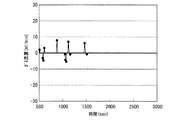
実施例5の燃料電池発電システムを用いて、25℃で発電試験を行った。水素製造装置2の水供給ポンプ36により、水収容容器35内の水35aを水素発生物質収容容器34へ供給して水素を発生させ、燃料電池1に水素を供給した。外部負荷4により、2.0Vの定電圧で燃料電池1を作動させ、4時間発電を行った。発電開始から40分後に、燃料電池1の水素製造装置2側のMEA100の電圧値(A)と、通気経路57側のMEA100の電圧値(B)の測定を開始し、200秒間測定を継続した。
<Power generation test>
Using the fuel cell power generation system of Example 5, a power generation test was performed at 25 ° C. The water 35 a in the water container 35 was supplied to the hydrogen generating substance container 34 by the water supply pump 36 of the hydrogen production apparatus 2 to generate hydrogen, and hydrogen was supplied to the fuel cell 1. The fuel cell 1 was operated at a constant voltage of 2.0 V by the external load 4 to generate power for 4 hours. Forty minutes after the start of power generation, measurement of the voltage value (A) of the MEA 100 on the hydrogen production device 2 side of the fuel cell 1 and the voltage value (B) of the MEA 100 on the ventilation path 57 side was started, and the measurement was continued for 200 seconds. .

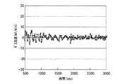
また、発電開始から500秒後に、マスフローメーター82により、燃料電池1に出入りするガスの流速の測定を開始し、発電開始から3000秒後まで測定を継続した。上記発電試験での、燃料電池1に出入りするガスの流速の時間変化を図27に示す。また、燃料電池1の水素製造装置2側のMEA100の電圧値(A)、および通気経路57側のMEA100の電圧値(B)の変化を図28に示す。それぞれの電圧値は、モニタリング開始時の値を基準とする相対値で示している。   Further, 500 seconds after the start of power generation, measurement of the flow rate of gas entering and exiting the fuel cell 1 was started by the mass flow meter 82, and the measurement was continued until 3000 seconds after the start of power generation. FIG. 27 shows the change over time in the flow rate of the gas entering and exiting the fuel cell 1 in the power generation test. FIG. 28 shows changes in the voltage value (A) of the MEA 100 on the hydrogen production device 2 side of the fuel cell 1 and the voltage value (B) of the MEA 100 on the ventilation path 57 side. Each voltage value is shown as a relative value based on the value at the start of monitoring.

チェックバルブ(逆流防止部58a、58b)を設置している実施例5のシステムでは、図27に示されるように、ガスの流速が全体的に安定しており、一方、瞬間的に大きな圧力変動があった場合は、開弁してガスを通気し、圧力変動を効果的に抑制していることがわかる。このため、図28に示されるように、安定して燃料電池1を作動させることができた。比較のため、逆流防止部58a、58bを設けずに、通気経路57と81とを直接接続して構成した燃料電池発電システムにおけるガスの流速の時間変化を図29に示すが、ガスの流速は、全体的にマイナス側に振れつつ大きく変動しており、燃料電池1内に供給される水素の圧力変動によって、燃料電池1の内圧が変動しやすいことがわかる。このため、燃料電池1の出力は、燃料電池1内に供給される水素の圧力変動の影響を受けやすくなる。   In the system of the fifth embodiment in which check valves (reverse flow prevention portions 58a and 58b) are installed, as shown in FIG. 27, the gas flow rate is stable as a whole, while large pressure fluctuations are instantaneously generated. When there is, it is understood that the valve is opened and gas is vented to effectively suppress the pressure fluctuation. For this reason, as shown in FIG. 28, the fuel cell 1 could be operated stably. For comparison, FIG. 29 shows the time change of the gas flow rate in the fuel cell power generation system configured by directly connecting the ventilation paths 57 and 81 without providing the backflow prevention units 58a and 58b. It can be seen that, as a whole, it fluctuates greatly while swinging to the negative side, and the internal pressure of the fuel cell 1 tends to fluctuate due to the pressure fluctuation of the hydrogen supplied into the fuel cell 1. For this reason, the output of the fuel cell 1 is easily affected by the pressure fluctuation of the hydrogen supplied into the fuel cell 1.

本発明は、その趣旨を逸脱しない範囲で、上記以外の形態としても実施が可能である。本出願に開示された実施形態は一例であって、これらに限定はされない。本発明の範囲は、上述の明細書の記載よりも、添付されている請求の範囲の記載を優先して解釈され、請求の範囲と均等の範囲内での全ての変更は、請求の範囲に含まれるものである。   The present invention can be implemented in other forms than the above without departing from the spirit of the present invention. The embodiments disclosed in the present application are merely examples, and the present invention is not limited thereto. The scope of the present invention is construed in preference to the description of the appended claims rather than the description of the above specification, and all modifications within the scope equivalent to the claims are construed in the scope of the claims. It is included.

本発明の燃料電池発電システムでは、燃料電池の作動停止時における水素による燃料電池の劣化を、比較的簡易な機構で抑制できるため、システムの小型化も容易である。よって、本発明の燃料電池発電システムは、高機能のポータブル型電子機器の電源用途を始めとして、従来の燃料電池が適用されている各種用途に好ましく用いることができる。   In the fuel cell power generation system of the present invention, the deterioration of the fuel cell due to hydrogen when the fuel cell is stopped can be suppressed by a relatively simple mechanism, so that the system can be easily downsized. Therefore, the fuel cell power generation system of the present invention can be preferably used for various applications to which a conventional fuel cell is applied, including a power supply for a high-performance portable electronic device.

1 燃料電池
2 水素製造装置
3 水素除去装置
4 外部負荷
5、13 流路切替え部
6 燃料流路
7 ストップバルブ
8a、8b、15 開閉弁
9、12、14、18 逆流防止弁
10 抵抗
11 循環経路
16、17 ブロア
100 第1の膜・電極接合体
200 第2の膜・電極接合体
DESCRIPTION OF SYMBOLS 1 Fuel cell 2 Hydrogen production apparatus 3 Hydrogen removal apparatus 4 External load 5, 13 Flow path switching part 6 Fuel flow path 7 Stop valve 8a, 8b, 15 On-off valve 9, 12, 14, 18 Backflow prevention valve 10 Resistance 11 Circulation path 16, 17 Blower 100 First membrane / electrode assembly 200 Second membrane / electrode assembly

Claims (11)

酸素を還元する正極と、水素を酸化する負極と、前記正極と前記負極との間に配置された固体電解質膜とを含む第1の膜・電極接合体を含む燃料電池と、
前記燃料電池に水素を供給する燃料流路とを含む燃料電池発電システムであって、
前記燃料電池は、前記第1の膜・電極接合体を複数含み、
前記燃料流路に、前記システムの内部に存在する水素の少なくとも一部を除去することが可能な水素除去装置が接続されており、
前記水素除去装置は、酸素を還元する正極と、水素を酸化する負極と、該正極と該負極との間に配置された固体電解質膜とを含む第2の膜・電極接合体を含むことを特徴とする燃料電池発電システム。
A fuel cell including a first membrane-electrode assembly including a positive electrode for reducing oxygen, a negative electrode for oxidizing hydrogen, and a solid electrolyte membrane disposed between the positive electrode and the negative electrode;
A fuel cell power generation system including a fuel flow path for supplying hydrogen to the fuel cell,
The fuel cell includes a plurality of the first membrane / electrode assemblies,
A hydrogen removal device capable of removing at least a part of hydrogen present in the system is connected to the fuel flow path ,
The hydrogen removal apparatus includes a second membrane / electrode assembly including a positive electrode that reduces oxygen, a negative electrode that oxidizes hydrogen, and a solid electrolyte membrane disposed between the positive electrode and the negative electrode. A fuel cell power generation system.
前記燃料電池の作動時に、前記水素除去装置により、前記燃料電池に供給される水素流量を調整することのできる請求項1に記載の燃料電池発電システム。  The fuel cell power generation system according to claim 1, wherein a flow rate of hydrogen supplied to the fuel cell can be adjusted by the hydrogen removing device when the fuel cell is operated. 前記第1の膜・電極接合体の前記正極と前記負極とを、電気的に導通させることのできる請求項1に記載の燃料電池発電システム。  2. The fuel cell power generation system according to claim 1, wherein the positive electrode and the negative electrode of the first membrane-electrode assembly can be electrically connected. 前記第2の膜・電極接合体の前記正極と前記負極とを、電気的に導通させることのできる請求項に記載の燃料電池発電システム。2. The fuel cell power generation system according to claim 1 , wherein the positive electrode and the negative electrode of the second membrane-electrode assembly can be electrically connected. 前記燃料電池への水素の流入と外気の取り込みとを切替えることができる流路切替え部をさらに含み、
前記流路切替え部は、前記燃料電池と前記水素除去装置との間の前記燃料流路に配置されている請求項1に記載の燃料電池発電システム。
A flow path switching unit capable of switching between inflow of hydrogen into the fuel cell and intake of outside air;
The fuel cell power generation system according to claim 1, wherein the flow path switching unit is disposed in the fuel flow path between the fuel cell and the hydrogen removal device.
前記燃料電池への水素の流入と外気の取り込みとを切替えることができる流路切替え部をさらに含み、
前記流路切替え部は、前記燃料電池と前記水素除去装置との間の前記燃料流路に配置され、
少なくとも1つの前記第1の膜・電極接合体の電圧が1V以下に低下した後に、前記流路切替え部を作動させて前記システムの内部に外気を取り込む請求項1に記載の燃料電池発電システム。
A flow path switching unit capable of switching between inflow of hydrogen into the fuel cell and intake of outside air;
The flow path switching unit is disposed in the fuel flow path between the fuel cell and the hydrogen removal device,
2. The fuel cell power generation system according to claim 1, wherein after the voltage of at least one of the first membrane / electrode assemblies is lowered to 1 V or less, the flow path switching unit is operated to take outside air into the system.
前記燃料電池への水素の流入と外気の取り込みとを切替えることができる流路切替え部をさらに含み、
前記流路切替え部は、前記燃料電池と前記水素除去装置との間の前記燃料流路に配置され、
全ての前記第1の膜・電極接合体の電圧が0.2V以上の状態で、前記流路切替え部を作動させて前記システムの内部に外気を取り込む請求項1に記載の燃料電池発電システム。
A flow path switching unit capable of switching between inflow of hydrogen into the fuel cell and intake of outside air;
The flow path switching unit is disposed in the fuel flow path between the fuel cell and the hydrogen removal device,
2. The fuel cell power generation system according to claim 1, wherein the flow path switching unit is operated to take outside air into the system in a state where the voltages of all the first membrane-electrode assemblies are 0.2 V or more.
逆流防止部をさらに含み、
前記逆流防止部は、前記燃料電池の内部の余剰の水素を外部に放出させることのできる請求項1に記載の燃料電池発電システム。
Further including a backflow prevention unit,
The fuel cell power generation system according to claim 1, wherein the backflow prevention unit is capable of releasing excess hydrogen inside the fuel cell to the outside.
逆流防止部をさらに含み、
前記逆流防止部は、外気を燃料電池の内部に取り込むことのできる請求項1に記載の燃料電池発電システム。
Further including a backflow prevention unit,
The fuel cell power generation system according to claim 1, wherein the backflow prevention unit can take outside air into the fuel cell.
水素供給源をさらに含む請求項1に記載の燃料電池発電システム。  The fuel cell power generation system according to claim 1, further comprising a hydrogen supply source. 前記水素供給源は、水と反応して水素を発生する水素発生物質である請求項10に記載の燃料電池発電システム。The fuel cell power generation system according to claim 10 , wherein the hydrogen supply source is a hydrogen generating material that reacts with water to generate hydrogen.
JP2009505197A 2007-03-16 2008-03-14 Fuel cell power generation system Expired - Fee Related JP5073737B2 (en)

Priority Applications (1)

Application Number Priority Date Filing Date Title
JP2009505197A JP5073737B2 (en) 2007-03-16 2008-03-14 Fuel cell power generation system

Applications Claiming Priority (8)

Application Number Priority Date Filing Date Title
JP2007068276 2007-03-16
JP2007147649 2007-06-04
JP2007185209 2007-07-17
PCT/JP2008/054736 WO2008114722A1 (en) 2007-03-16 2008-03-14 Fuel cell power generation system
JP2009505197A JP5073737B2 (en) 2007-03-16 2008-03-14 Fuel cell power generation system

Publications (2)

Publication Number Publication Date
JPWO2008114722A1 JPWO2008114722A1 (en) 2010-07-01
JP5073737B2 true JP5073737B2 (en) 2012-11-14

Family

ID=39765830

Family Applications (2)

Application Number Title Priority Date Filing Date
JP2008063495A Pending JP2009043702A (en) 2007-03-16 2008-03-13 Fuel cell power generation system
JP2009505197A Expired - Fee Related JP5073737B2 (en) 2007-03-16 2008-03-14 Fuel cell power generation system

Family Applications Before (1)

Application Number Title Priority Date Filing Date
JP2008063495A Pending JP2009043702A (en) 2007-03-16 2008-03-13 Fuel cell power generation system

Country Status (4)

Country Link
US (1) US20100104900A1 (en)
JP (2) JP2009043702A (en)
KR (1) KR101111701B1 (en)
WO (1) WO2008114722A1 (en)

Families Citing this family (3)

* Cited by examiner, † Cited by third party
Publication number Priority date Publication date Assignee Title
DE102010023566A1 (en) * 2010-06-10 2011-12-15 Fraunhofer-Gesellschaft zur Förderung der angewandten Forschung e.V. Fuel cell and fuel cell stack
GB2507466B (en) * 2012-07-16 2015-04-08 Prometheus Wireless Ltd Fuel cell apparatus
US11777114B2 (en) 2017-11-27 2023-10-03 Infinity Fuel Cell And Hydrogen, Inc. Cascading stack electrochemical fuel cell

Citations (6)

* Cited by examiner, † Cited by third party
Publication number Priority date Publication date Assignee Title
JP2001229951A (en) * 2000-02-16 2001-08-24 Nissan Motor Co Ltd Fuel-cell system for moving object
JP2001345114A (en) * 2000-06-01 2001-12-14 Nissan Motor Co Ltd Fuel cell system
JP2002324564A (en) * 2001-04-26 2002-11-08 Equos Research Co Ltd Fuel cell device and control method therefor
JP2003109630A (en) * 2001-09-27 2003-04-11 Equos Research Co Ltd Fuel cell system
JP2003346870A (en) * 2002-05-31 2003-12-05 Mitsubishi Heavy Ind Ltd Polymer electrolyte fuel cell stack
JP2008210697A (en) * 2007-02-27 2008-09-11 Toshiba Fuel Cell Power Systems Corp Shutdown and storing method of fuel cell power generation system, program, and fuel cell power generation system

Family Cites Families (14)

* Cited by examiner, † Cited by third party
Publication number Priority date Publication date Assignee Title
GB1179033A (en) * 1966-05-31 1970-01-28 Atlantic Richfield Co Fuel Cell and Method of Operation thereof
JP3871792B2 (en) * 1997-12-25 2007-01-24 株式会社豊田自動織機 Fuel cell device
DE10054050A1 (en) * 2000-10-31 2002-05-16 Siemens Ag Method for operating an HT-PEM fuel cell system and associated fuel cell system
ATE287579T1 (en) * 2001-05-22 2005-02-15 Umicore Ag & Co Kg METHOD FOR PRODUCING A MEMBRANE ELECTRODE UNIT AND MEMBRANE ELECTRODE UNIT PRODUCED THEREFROM
JP2003187836A (en) * 2001-12-18 2003-07-04 Tokyo Gas Co Ltd Hydrogen supply mechanism
JP4432312B2 (en) * 2002-08-09 2010-03-17 株式会社エクォス・リサーチ Fuel cell device
US6913845B2 (en) 2002-10-28 2005-07-05 Utc Fuel Cells, Llc Reducing fuel cell cathode potential during startup and shutdown
JP2004296340A (en) * 2003-03-27 2004-10-21 Nissan Motor Co Ltd Fuel cell system
JP4055639B2 (en) * 2003-04-28 2008-03-05 トヨタ自動車株式会社 Operation control of power supply system with fuel cell
JP2005038668A (en) * 2003-07-18 2005-02-10 Toyota Motor Corp Fuel cell system
JP4455040B2 (en) 2003-12-16 2010-04-21 新日本石油株式会社 Fuel cell system and operation method thereof
JP2006079928A (en) * 2004-09-09 2006-03-23 Babcock Hitachi Kk Fuel cell system and method for stopping its operation
JP2006156040A (en) * 2004-11-26 2006-06-15 Nissan Motor Co Ltd Fuel cell system
JP5100008B2 (en) * 2005-01-18 2012-12-19 セイコーインスツル株式会社 Operation method of fuel cell system and fuel cell system

Patent Citations (6)

* Cited by examiner, † Cited by third party
Publication number Priority date Publication date Assignee Title
JP2001229951A (en) * 2000-02-16 2001-08-24 Nissan Motor Co Ltd Fuel-cell system for moving object
JP2001345114A (en) * 2000-06-01 2001-12-14 Nissan Motor Co Ltd Fuel cell system
JP2002324564A (en) * 2001-04-26 2002-11-08 Equos Research Co Ltd Fuel cell device and control method therefor
JP2003109630A (en) * 2001-09-27 2003-04-11 Equos Research Co Ltd Fuel cell system
JP2003346870A (en) * 2002-05-31 2003-12-05 Mitsubishi Heavy Ind Ltd Polymer electrolyte fuel cell stack
JP2008210697A (en) * 2007-02-27 2008-09-11 Toshiba Fuel Cell Power Systems Corp Shutdown and storing method of fuel cell power generation system, program, and fuel cell power generation system

Also Published As

Publication number Publication date
KR20090101503A (en) 2009-09-28
WO2008114722A1 (en) 2008-09-25
JPWO2008114722A1 (en) 2010-07-01
JP2009043702A (en) 2009-02-26
KR101111701B1 (en) 2012-02-23
US20100104900A1 (en) 2010-04-29

Similar Documents

Publication Publication Date Title
JP4951847B2 (en) Fuel cell activation method
JP2009221072A (en) Cartridge for hydrogen supply and fuel cell power generation system
US7759012B2 (en) Direct methanol fuel cell system and operating method thereof
JP2011000566A (en) Gas-liquid separator, apparatus for producing hydrogen, and fuel cell system
JP5073737B2 (en) Fuel cell power generation system
JP2009187729A (en) Fuel cell
US20110117465A1 (en) Fuel cell
JP2007207679A (en) Hollow platinum catalyst particle for fuel cell, membrane electrode assembly, manufacturing method of them, and fuel cell
US7998636B2 (en) Polymer electrolyte fuel cell stack
US20130022882A1 (en) Fuel cell system
JP2007317496A (en) Fuel cell power generation system
JP2011165395A (en) Fuel cell
JP2009123469A (en) Fuel battery power generation system
JP2010033979A (en) Fuel-cell electric power generation system
JP2010218929A (en) Fuel cell power generation system
JP2009129608A (en) Fuel cell, and fuel cell power generation system and power generation method
JP2011113912A (en) Fuel cell
JP2007066688A (en) Fuel cell
JP2010055954A (en) Electrode, fuel cell using the same, and electronic device
JP2012113876A (en) Fuel cell system
JP2010135156A (en) Fuel cell
JP2011206756A (en) Gas-liquid separator, hydrogen production apparatus, and fuel cell system
CN101617430A (en) Fuel cell generation
JP2009259736A (en) Fuel cell electric power generating system
JP2008066173A (en) Fuel cell

Legal Events

Date Code Title Description
A711 Notification of change in applicant

Free format text: JAPANESE INTERMEDIATE CODE: A712

Effective date: 20110520

RD02 Notification of acceptance of power of attorney

Free format text: JAPANESE INTERMEDIATE CODE: A7422

Effective date: 20110527

A131 Notification of reasons for refusal

Free format text: JAPANESE INTERMEDIATE CODE: A131

Effective date: 20120410

A521 Written amendment

Free format text: JAPANESE INTERMEDIATE CODE: A523

Effective date: 20120529

TRDD Decision of grant or rejection written
A01 Written decision to grant a patent or to grant a registration (utility model)

Free format text: JAPANESE INTERMEDIATE CODE: A01

Effective date: 20120807

A01 Written decision to grant a patent or to grant a registration (utility model)

Free format text: JAPANESE INTERMEDIATE CODE: A01

A61 First payment of annual fees (during grant procedure)

Free format text: JAPANESE INTERMEDIATE CODE: A61

Effective date: 20120822

R150 Certificate of patent or registration of utility model

Free format text: JAPANESE INTERMEDIATE CODE: R150

FPAY Renewal fee payment (event date is renewal date of database)

Free format text: PAYMENT UNTIL: 20150831

Year of fee payment: 3

S111 Request for change of ownership or part of ownership

Free format text: JAPANESE INTERMEDIATE CODE: R313111

FPAY Renewal fee payment (event date is renewal date of database)

Free format text: PAYMENT UNTIL: 20150831

Year of fee payment: 3

R350 Written notification of registration of transfer

Free format text: JAPANESE INTERMEDIATE CODE: R350

FPAY Renewal fee payment (event date is renewal date of database)

Free format text: PAYMENT UNTIL: 20150831

Year of fee payment: 3

LAPS Cancellation because of no payment of annual fees