JP5069449B2 - Wiring board and manufacturing method thereof - Google Patents
Wiring board and manufacturing method thereof Download PDFInfo
- Publication number
- JP5069449B2 JP5069449B2 JP2006308322A JP2006308322A JP5069449B2 JP 5069449 B2 JP5069449 B2 JP 5069449B2 JP 2006308322 A JP2006308322 A JP 2006308322A JP 2006308322 A JP2006308322 A JP 2006308322A JP 5069449 B2 JP5069449 B2 JP 5069449B2
- Authority
- JP
- Japan
- Prior art keywords
- layer
- wiring
- substrate
- pad
- resist
- Prior art date
- Legal status (The legal status is an assumption and is not a legal conclusion. Google has not performed a legal analysis and makes no representation as to the accuracy of the status listed.)
- Active
Links
Images


Classifications
-
- H—ELECTRICITY
- H01—ELECTRIC ELEMENTS
- H01L—SEMICONDUCTOR DEVICES NOT COVERED BY CLASS H10
- H01L2224/00—Indexing scheme for arrangements for connecting or disconnecting semiconductor or solid-state bodies and methods related thereto as covered by H01L24/00
- H01L2224/01—Means for bonding being attached to, or being formed on, the surface to be connected, e.g. chip-to-package, die-attach, "first-level" interconnects; Manufacturing methods related thereto
- H01L2224/10—Bump connectors; Manufacturing methods related thereto
- H01L2224/15—Structure, shape, material or disposition of the bump connectors after the connecting process
- H01L2224/16—Structure, shape, material or disposition of the bump connectors after the connecting process of an individual bump connector
- H01L2224/161—Disposition
- H01L2224/16151—Disposition the bump connector connecting between a semiconductor or solid-state body and an item not being a semiconductor or solid-state body, e.g. chip-to-substrate, chip-to-passive
- H01L2224/16221—Disposition the bump connector connecting between a semiconductor or solid-state body and an item not being a semiconductor or solid-state body, e.g. chip-to-substrate, chip-to-passive the body and the item being stacked
- H01L2224/16225—Disposition the bump connector connecting between a semiconductor or solid-state body and an item not being a semiconductor or solid-state body, e.g. chip-to-substrate, chip-to-passive the body and the item being stacked the item being non-metallic, e.g. insulating substrate with or without metallisation
-
- H—ELECTRICITY
- H01—ELECTRIC ELEMENTS
- H01L—SEMICONDUCTOR DEVICES NOT COVERED BY CLASS H10
- H01L2224/00—Indexing scheme for arrangements for connecting or disconnecting semiconductor or solid-state bodies and methods related thereto as covered by H01L24/00
- H01L2224/01—Means for bonding being attached to, or being formed on, the surface to be connected, e.g. chip-to-package, die-attach, "first-level" interconnects; Manufacturing methods related thereto
- H01L2224/26—Layer connectors, e.g. plate connectors, solder or adhesive layers; Manufacturing methods related thereto
- H01L2224/31—Structure, shape, material or disposition of the layer connectors after the connecting process
- H01L2224/32—Structure, shape, material or disposition of the layer connectors after the connecting process of an individual layer connector
- H01L2224/321—Disposition
- H01L2224/32151—Disposition the layer connector connecting between a semiconductor or solid-state body and an item not being a semiconductor or solid-state body, e.g. chip-to-substrate, chip-to-passive
- H01L2224/32221—Disposition the layer connector connecting between a semiconductor or solid-state body and an item not being a semiconductor or solid-state body, e.g. chip-to-substrate, chip-to-passive the body and the item being stacked
- H01L2224/32225—Disposition the layer connector connecting between a semiconductor or solid-state body and an item not being a semiconductor or solid-state body, e.g. chip-to-substrate, chip-to-passive the body and the item being stacked the item being non-metallic, e.g. insulating substrate with or without metallisation
-
- H—ELECTRICITY
- H01—ELECTRIC ELEMENTS
- H01L—SEMICONDUCTOR DEVICES NOT COVERED BY CLASS H10
- H01L2224/00—Indexing scheme for arrangements for connecting or disconnecting semiconductor or solid-state bodies and methods related thereto as covered by H01L24/00
- H01L2224/73—Means for bonding being of different types provided for in two or more of groups H01L2224/10, H01L2224/18, H01L2224/26, H01L2224/34, H01L2224/42, H01L2224/50, H01L2224/63, H01L2224/71
- H01L2224/732—Location after the connecting process
- H01L2224/73201—Location after the connecting process on the same surface
- H01L2224/73203—Bump and layer connectors
- H01L2224/73204—Bump and layer connectors the bump connector being embedded into the layer connector
Landscapes
- Structure Of Printed Boards (AREA)
- Manufacturing Of Printed Wiring (AREA)
Description
本発明は、配線基板を製造する技術に係り、より詳細には、半導体素子(チップ)を搭載する実装用基板として供され、その半導体素子をフリップチップ接続する際に使用されるパッドを備えた配線基板及びその製造方法に関する。 The present invention relates to a technique for manufacturing a wiring board, and more particularly, provided as a mounting board on which a semiconductor element (chip) is mounted, and includes a pad used for flip-chip connection of the semiconductor element. The present invention relates to a wiring board and a manufacturing method thereof.
半導体素子(チップ)と実装用基板とを電気的に接続する方法としては、従来よりワイヤボンディングが一般的である。この方法を用いて半導体装置を構成する場合、基板上にチップの裏面(電極端子が形成されている側と反対側の面)を下にして接着剤等により固定化した後、当該チップの電極端子(以下、「チップパッド」ともいう)と基板上に形成されたパッド(以下、「基板パッド」ともいう)とをボンディングワイヤで接続し、さらにワイヤ及びチップを覆うように樹脂で封止している。この構造では、基板上でチップ搭載エリアの周囲に、基板パッドとワイヤボンディングするための余分なスペースを必要とする。 As a method for electrically connecting a semiconductor element (chip) and a mounting substrate, wire bonding has been generally used. When a semiconductor device is configured using this method, the chip is fixed on the substrate with an adhesive or the like with the back surface of the chip (the surface opposite to the side where the electrode terminals are formed) down, and then the electrode of the chip Terminals (hereinafter also referred to as “chip pads”) and pads formed on the substrate (hereinafter also referred to as “substrate pads”) are connected by bonding wires, and further sealed with resin so as to cover the wires and chips. ing. This structure requires an extra space for wire bonding with the substrate pad around the chip mounting area on the substrate.
その一方で、近年、電子機器や装置の小型化の要求に伴い、それに用いられる半導体装置の小型化、高密度化が図られている。例えば、半導体装置の形状を個々の半導体チップの形状に極力近づけることで小型化及び高密度化を図るようにしたCSP(チップサイズパッケージ)等の半導体装置が開発され、実用化されている。かかる半導体装置では、ワイヤボンディング接続とは異なる形態のフリップチップ接続の技術を用いて半導体チップを基板に実装することで、より一層の小型化及び高密度化を図り、電気信号の高速処理を可能としている。 On the other hand, in recent years, along with the demand for downsizing of electronic devices and devices, downsizing and high density of semiconductor devices used therefor have been attempted. For example, a semiconductor device such as a CSP (chip size package) has been developed and put into practical use so that the size of the semiconductor device can be reduced as much as possible by making the shape of the semiconductor device as close as possible to the shape of each semiconductor chip. In such a semiconductor device, the semiconductor chip is mounted on the substrate using a flip chip connection technique different from the wire bonding connection, so that further miniaturization and high density can be achieved, and high-speed processing of electrical signals is possible. It is said.
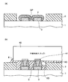
従来のフリップチップ実装用基板は、図1に概略的に示すように、搭載する半導体素子の接続部分(チップパッド)に対応する領域において、その表面が断面的に見て凹凸形状となっている。つまり、フリップチップ接続用の基板パッド3(基板1上に形成された配線パターンの一部分に画定される領域)の上面と基板1の表面(基板1上に形成されたソルダレジスト等からなる絶縁層2の上面)との間に段差があった。
As shown schematically in FIG. 1, a conventional flip chip mounting substrate has a concavo-convex shape as viewed from a cross section in a region corresponding to a connection portion (chip pad) of a semiconductor element to be mounted. . That is, the upper surface of the
上記のフリップチップ接続に関連する技術としては、例えば、特許文献1に記載されるように、配線基板の表面にフリップチップ接続用の接続パッドと共にワイヤボンディング接続用のボンディングパッドも併せて形成するようにしたものがある。この文献に記載された技術では、基板の表面に接続パッドとボンディングパッドをパターン形成した後、接続パッドを遮蔽してボンディングパッドの表面にボンディング用のめっきを施し、次にボンディングパッド形成領域にマスキング用テープを粘着してボンディングパッドを遮蔽した後、接続パッドの表面に粘着層を被着させてその表面にはんだ粉を付着させ、テープを剥離した後、リフローによりはんだ粉を溶融して接続パッドにはんだを被着させるようにしている。また、特許文献2に記載されるように、フリップチップ実装構造において半導体素子の各電極にそれぞれ形成したはんだバンプ間がショートするのを防止するようにしたものがある。このフリップチップ実装構造では、半導体素子側に形成した各はんだバンプに対応する実装用基板の当該部位に基板側電極を形成すると共に、各基板側電極の間の部位に溝を2条形成し、はんだバンプを加熱、溶融させて半導体素子の電極と実装用基板の電極とを接続した時に、余分なはんだが基板側電極上からはみ出して実装用基板の溝内に流れこむようにすることで、隣接するバンプ間のショートを防止している。また、特許文献3に記載されるように、絶縁層と配線導体とが交互に積層された配線基板において、最外層の絶縁層上に帯状配線導体を複数並べて配設するとともに、該帯状配線導体の一部に、半導体素子の電極端子がフリップチップ接続される導電突起を帯状配線導体の幅と一致する幅で形成し、さらに導電突起の少なくとも上面が露出するようにソルダレジスト層で被覆したものがある。
上述したように従来のフリップチップ実装用基板では(図1参照)、フリップチップ接続用の基板パッド3の上面と基板表面(基板1上に形成された絶縁層2の上面)との間に段差があり、断面的に見て実装用基板の表面が凹凸形状となっていたため、この基板に半導体素子を搭載して半導体装置を構成する際に、以下の不都合があった。
As described above, in the conventional flip chip mounting substrate (see FIG. 1), there is a step between the upper surface of the
すなわち、基板パッドと半導体素子のチップパッドを接続するための手段としては、典型的にはんだバンプが用いられるが、その形成方法として、フォトプロセスを用いためっき法やメタルマスクを用いた蒸着法などが主流である一方、基板パッドが微細な間隔(ピッチ)で形成されている基板にあっては、基板パッドにはんだを被着させる際に、スーパージャフィット法と呼ばれる手法が用いられている。これは、Sn−Ag系、Sn−Zn系などのPbフリー組成のはんだ合金で部品を実装するのに十分なはんだ量を供給しておき、粘着性フラックスで部品を仮付けし、大気雰囲気中で一括リフローする工法であり、上記の特許文献1にも記載されているように、基板パッドの表面に粘着層を形成してはんだ粉を基板パッド上に付着させ、そのはんだ粉を溶融させて基板パッドの表面にはんだを被着させる方法である。
That is, as a means for connecting the substrate pad and the chip pad of the semiconductor element, a solder bump is typically used. As a method for forming the method, a plating method using a photo process, a vapor deposition method using a metal mask, or the like is used. On the other hand, in a substrate in which substrate pads are formed at a fine interval (pitch), a technique called a super just method is used when solder is applied to the substrate pads. This is done by supplying a sufficient amount of solder to mount the component with a Pb-free solder alloy such as Sn—Ag or Sn—Zn, and temporarily attaching the component with an adhesive flux. As described in
かかるスーパージャフィット法を用いてはんだ粉を基板パッドの表面に吸着させると、上述したように基板の表面には凹凸の段差があるため、微細ピッチになればなるほど(現状の技術では20μmピッチのフリップチップ実装用基板も出現している)、図1(a)に例示するように、隣接する基板パッド3の対向する側面に吸着されたはんだ粉4同士がショート(短絡)もしくはブリッジ(橋絡)を起こしてしまい(図中、破線で囲んだSPで示す部分)、不良発生要因の一つとなる。
When the solder powder is adsorbed on the surface of the substrate pad by using the super just method, as described above, the surface of the substrate has uneven steps, so that the finer the pitch (the current technology has a pitch of 20 μm). As shown in FIG. 1A, the solder powder 4 adsorbed on the opposite side surfaces of the
また、図1(b)に例示するように、半導体素子40(チップパッド41)をはんだバンプ5を介して実装用基板(基板パッド3)にフリップチップ接続した後に両者間にアンダーフィル樹脂6を充填する際に、基板表面には凹凸の段差があるため、アンダーフィル樹脂6の流動性が不均一となり、またピッチも狭くなっているため、樹脂6が内部に入りにくくなる。このため、図示のように注入した樹脂の一部にボイド(空洞部分)VDが発生したり、あるいは充填不足の要因となりうる。
Further, as illustrated in FIG. 1B, after the semiconductor element 40 (chip pad 41) is flip-chip connected to the mounting substrate (substrate pad 3) via the
本発明は、かかる従来技術における課題に鑑み創作されたもので、半導体素子を搭載して半導体装置を構成する際に、隣接する基板パッド上に付着されるはんだ粉同士のショートを防止すると共に、アンダーフィル樹脂の充填の際の不良発生要因を実質的に無くすことができる配線基板及びその製造方法を提供することを目的とする。 The present invention was created in view of the problems in the prior art, and when a semiconductor device is mounted and a semiconductor device is configured, a short circuit between solder powders attached on adjacent substrate pads is prevented. It is an object of the present invention to provide a wiring board and a method of manufacturing the same that can substantially eliminate the cause of defects when filling with an underfill resin.
上記の従来技術の課題を解決するため、本発明の一形態によれば、ベース基材としての基板上に形成されたフリップチップ接続用のパッド部分を含む配線層と、前記パッド部分のみを露出させて前記基板及び前記配線層を覆うように形成された絶縁層とを備え、前記配線層は、配線部分を構成する第1のめっき配線の一部領域上にのみ、前記パッド部分を構成する、前記第1のめっき配線と結晶配向が異なる第2のめっき配線が積み重ねられた構造を有し、前記パッド部分の上面が前記絶縁層の表面と同一面上に位置するように形成されていることを特徴とする配線基板が提供される。 In order to solve the above-described problems of the prior art, according to one aspect of the present invention, a wiring layer including a flip chip connecting pad portion formed on a substrate as a base substrate, and only the pad portion are exposed. And an insulating layer formed so as to cover the substrate and the wiring layer, and the wiring layer constitutes the pad portion only on a partial region of the first plated wiring constituting the wiring portion. The second plated wiring having a crystal orientation different from that of the first plated wiring is stacked, and the upper surface of the pad portion is formed on the same plane as the surface of the insulating layer. A wiring board is provided.
この形態に係る配線基板の構成によれば、フリップチップ接続用のパッド部分(第2のめっき配線)が、これと結晶配向の異なる配線部分(第1のめっき配線)の一部領域上にのみ積み重ねられた構造となっており、そのパッド部分(基板パッド)の上面は絶縁層の表面(配線基板の表面)と同一面上に位置している。つまり、基板パッドの側面は外部に露出せず、その上面のみが露出する。これに対し、従来の技術(図1)では基板パッド3の側面も露出していた。
According to the configuration of the wiring board according to this embodiment, the flip chip connecting pad portion (second plating wiring) is only on a partial region of the wiring portion (first plating wiring) having a different crystal orientation from this. The upper surface of the pad portion (substrate pad) is located on the same plane as the surface of the insulating layer (surface of the wiring substrate). That is, the side surface of the substrate pad is not exposed to the outside, and only the upper surface thereof is exposed. In contrast, in the conventional technique (FIG. 1), the side surface of the
従って、フリップチップ接続のためのはんだを基板パッドに被着させる際にはんだ粉を基板パッドの表面に吸着させると、本発明の配線基板では、基板パッドの上面にのみはんだ粉を吸着させることができる。これにより、従来の技術(図1(a))に見られたような隣接する基板パッド3(その対向する側面)上のはんだ粉4同士のショート等を防止することができる。 Accordingly, when the solder powder is adsorbed on the surface of the substrate pad when the solder for flip chip connection is applied to the substrate pad, the wiring substrate of the present invention can adsorb the solder powder only on the upper surface of the substrate pad. it can. Thereby, the short circuit etc. of the solder powder 4 on the adjacent board | substrate pad 3 (the side surface which opposes) like the conventional technique (FIG.1 (a)) can be prevented.
また、本発明の配線基板に半導体素子をフリップチップ接続した後に両者間にアンダーフィル樹脂を充填する際にも、基板パッドと基板表面は同一面にあるので、アンダーフィル樹脂を比較的スムーズに流動させることができ、樹脂が内部に入り易くなる。これにより、従来の技術(図1(b))に見られたようなボイドVDの発生や充填不足といった不良発生要因を実質的に無くすことができる。このことは、客先(本配線基板に半導体素子を搭載するメーカなど)での歩留り改善に大いに寄与する。 In addition, when a semiconductor element is flip-chip connected to the wiring board of the present invention and the underfill resin is filled between the two, the substrate pad and the substrate surface are on the same surface, so that the underfill resin flows relatively smoothly. The resin can easily enter the inside. As a result, it is possible to substantially eliminate the cause of defects such as the generation of voids VD and insufficient filling as seen in the prior art (FIG. 1B). This greatly contributes to yield improvement at customers (such as manufacturers that mount semiconductor elements on this wiring board).
また、本発明の他の形態によれば、上記の形態に係る配線基板を製造する方法が提供される。その一形態に係る配線基板の製造方法は、少なくとも最表層に導体層が形成された基板の一方の面に、形成すべきフリップチップ接続用のパッド部分を含む所要の配線層の形状に従ってパターニングされた開口部を備えた第1のレジスト層を形成する工程と、前記第1のレジスト層の開口部から露出している前記導体層を給電層として電解めっきを施し、当該開口部内を部分的に埋め込むように第1の配線層を形成する工程と、電解めっきの条件を変えて前記第1の配線層に電解めっきを施し、当該開口部内の残りの部分を埋め込むように前記第1の配線層と結晶配向が異なる第2の配線層を形成する工程と、前記第2の配線層のパッド部分に対応する領域にパターンが残るように、前記第1のレジスト層及び前記第2の配線層の上に第2のレジスト層を形成する工程と、前記第2のレジスト層をマスクにして、前記第2の配線層の露出している部分のみをエッチングすることで、前記第1の配線層を露出させる工程と、前記第2のレジスト層及び第1のレジスト層を除去した後、前記基板及び前記第1、第2の配線層を覆って全面に絶縁層を形成する工程と、前記絶縁層を研磨して前記パッド部分の上面を露出させると共に、基板表面全体を平坦化する工程とを含むことを特徴とする。 Moreover, according to the other form of this invention, the method of manufacturing the wiring board which concerns on said form is provided. The method for manufacturing a wiring board according to the embodiment is patterned in accordance with the shape of a required wiring layer including a pad portion for flip chip connection to be formed on at least one surface of the board having a conductor layer formed on the outermost layer. Forming a first resist layer having an opening, and performing electroplating using the conductive layer exposed from the opening of the first resist layer as a power feeding layer, and partially opening the opening A step of forming a first wiring layer so as to be embedded, and electrolytic plating is performed on the first wiring layer by changing a condition of electrolytic plating, and the first wiring layer is embedded so as to embed the remaining portion in the opening. Forming a second wiring layer having a crystal orientation different from that of the first resist layer and the second wiring layer so that a pattern remains in a region corresponding to a pad portion of the second wiring layer. Second on Forming a resist layer, and the second resist layer as a mask, only the exposed portions of said second wiring layer by etching, thereby exposing the first wiring layer, After removing the second resist layer and the first resist layer, a step of forming an insulating layer over the substrate and the first and second wiring layers, polishing the insulating layer, and And exposing the upper surface of the pad portion and planarizing the entire substrate surface.
本発明に係る配線基板及びその製造方法の他の構成/プロセス上の特徴及びそれに基づく有利な利点等については、後述する発明の実施の形態を参照しながら説明する。 Other configuration / process characteristics and advantageous advantages based on the structure / process of the wiring board and the manufacturing method thereof according to the present invention will be described with reference to embodiments of the invention described later.
以下、本発明の好適な実施の形態について、添付の図面を参照しながら説明する。 DESCRIPTION OF EXEMPLARY EMBODIMENTS Hereinafter, preferred embodiments of the invention will be described with reference to the accompanying drawings.
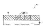
図2は本発明の一実施形態に係る配線基板(フリップチップ実装用基板)の構成を断面図の形態で示したものである。 FIG. 2 is a cross-sectional view showing the configuration of a wiring board (flip chip mounting board) according to an embodiment of the present invention.
図中、10は本実施形態に係る配線基板、12は配線基板10のベース基材としての樹脂基板、14は樹脂基板12上に形成された配線層、16は樹脂基板12上に形成された保護膜としての絶縁層を示す。配線層14は、図示のように上下に積み重ねられた2つの部分からなり、上側の部分は本発明を特徴付ける「基板パッド」部分14aを構成し、下側の部分は「下配線」部分14bを構成する。
In the figure, 10 is a wiring substrate according to the present embodiment, 12 is a resin substrate as a base material of the
樹脂基板12の形態としては、少なくとも最表層に導体層(図2には明示されていないが、「下配線」部分14bの一部として含まれている)が形成された基板であって、各導体層が基板内部を通して電気的に接続されている形態のものであれば十分である。樹脂基板12の内部には配線層が形成されていてもよいし、形成されていなくてもよい。本発明を特徴付ける部分ではないので特に図示はしないが、樹脂基板12の内部に配線層が形成されている形態の場合、基板内部で絶縁層を介在させて形成された各配線層及び各配線層間を相互に接続するビアホールを介して最表層の各導体層が電気的に接続されている。この形態の基板としては、例えば、ビルドアップ法を用いて形成され得る多層配線基板がある。一方、樹脂基板12の内部に配線層が形成されていない形態の場合、樹脂基板12の所要箇所に適宜形成されたスルーホールを介して最表層の各導体層が電気的に接続されている。この形態の基板としては、例えば、上記のビルドアップ法による多層配線基板のベース基材に相当するコア基板、すなわち、ガラス布にエポキシ樹脂、ポリイミド樹脂、ビスマレイミド・トリアジン(BT)樹脂、ポリフェニレンエーテル(PPE)樹脂等の絶縁性樹脂を含浸させたシートを所要枚数重ね、その両面もしくは片面に銅箔を被着させた基板(両面銅張積層板もしくは片面銅張積層板)がある。
The form of the
本実施形態に係る配線基板10は、図2にも示されるように、配線層14の「基板パッド」部分14aの上面が基板10の表面(絶縁層16の表面)と同一面上に位置するように形成されていることを特徴とする。本実施形態の配線基板10を構成する各構成部材の材料や大きさ等については、後述するプロセスに関連させて具体的に説明する。
In the
以下、本実施形態に係る配線基板10を製造する方法について、その製造工程を順に示す図3〜図6を参照しながら説明する。なお、各図(断面図、上面図、斜視図)に示す構成では、図示の簡単化のため、本発明に関連する部分(「基板パッド」部分14aを含む配線層14及びその周辺部分)のみが示されている。
Hereinafter, a method for manufacturing the
先ず最初の工程では(図3(a)参照)、通常のサブトラクティブ法、セミアディティブ法などを用いて所要形態の樹脂基板12を用意する。この基板12の形態としては、上述したように少なくとも最表層に導体層が形成された基板であって、各導体層が基板内部を通して電気的に接続されている形態のものであれば十分である。図示の例では、本発明に関連する部分として、樹脂基板12の一方の最表層(半導体チップが搭載される側)に導体層13が形成された状態の断面構造が示されており、この導体層13は、後述するように電解めっきを行う際の給電層(シード層)として利用され、例えば、2〜3μm程度の厚さに形成されている。導体層13の材料としては銅(Cu)が用いられ、樹脂基板12を構成する樹脂としては、熱硬化性のポリイミド樹脂、エポキシ樹脂、BT樹脂等が用いられる。
First, in the first step (see FIG. 3A), a
次の工程では(図3(b)参照)、樹脂基板12の導体層13が形成されている側の面に、パターニング材料を使用してレジスト層21を形成し、このレジスト層21の所定の箇所に対応する部分を除去する(開口部OPの形成)。この開口部OPは、本発明を特徴付ける「基板パッド」部分を含む所要の配線層の形状に従ってパターン形成される。基板上での「基板パッド」部分の配置については、搭載する半導体チップの電極端子(チップパッド)の配列形態に応じて、当該チップの周辺部分に対応する領域にのみ配置した「ペリフェラル型」、当該チップに対応する全領域にマトリクス状に配置した「エリアアレイ型」のいずれであってもよい。
In the next step (see FIG. 3B), a resist
また、パターニング材料としては、感光性のドライフィルム又は液状のフォトレジストを用いることができる。例えば、ドライフィルムを使用する場合には、典型的にレジスト材料をポリエステルのカバーシートとポリエチレンのセパレータシートの間に挟んだ構造となっているので、表面洗浄→ラミネーション前処理(セパレータシート剥離)→大気中でのレジストラミネーション→露光→カバーシート剥離→現像の工程を経て、パターニングされたレジスト層21を形成する。具体的には、樹脂基板12(導体層13)上に、所定の厚さ(本実施形態では、25μm程度)の感光性ドライフィルムを熱圧着により貼り付けた後、そのドライフィルムに対し、所要の形状にパターニングされたマスク(図示せず)を用いて紫外線(UV)照射による露光を施して硬化させ、さらに所定の現像液(ネガ型のレジストの場合には有機溶剤を含む現像液、ポジ型のレジストの場合にはアルカリ系の現像液)を用いてエッチング除去を行うことで(開口部OPの形成)、所要の配線パターンの形状に応じたレジスト層21を形成する。同様に、液状のフォトレジストを用いた場合にも、表面洗浄→表面にレジスト塗布→乾燥→露光→現像の工程を経て、所要の形状にパターニングされたレジスト層21を形成することができる。
As the patterning material, a photosensitive dry film or a liquid photoresist can be used. For example, when a dry film is used, since the resist material is typically sandwiched between a polyester cover sheet and a polyethylene separator sheet, surface cleaning → lamination pretreatment (separator sheet peeling) → A patterned resist
次の工程では(図3(c)参照)、レジスト層21の開口部OPから露出しているシード層(Cu)13を給電層として電解銅(Cu)めっきを施し、開口部OPを埋め込むように「厚付け配線めっき」を行うことで配線層14を形成する。形成された配線層14の上面は、図示の例では平坦となっているが、必ずしも平坦とは限らない。このため、厚付け配線めっきを行った後、表面全体を平坦化(平滑化)する処理を施すのが望ましい。この平坦化処理は、次の工程で形成されるレジストとの密着性を高めることにも寄与する。なお、この工程で形成された配線層14は、特に図示はしないが、樹脂基板12の所要箇所に適宜形成されたスルーホールを介して、あるいは基板内部の所要箇所に適宜形成された各配線層及び各配線層間を相互に接続するビアホールを介して、基板の裏面側(半導体チップが搭載される側と反対側の面)の配線層に電気的に接続されている。
In the next step (see FIG. 3C), electrolytic copper (Cu) plating is performed using the seed layer (Cu) 13 exposed from the opening OP of the resist
次の工程では(図3(d)参照)、ドライフィルム等からなるレジスト層21をそのまま残した状態で、さらにレジスト層21及び配線層14の全面に、パターニング材料を使用してレジスト層22を形成する。このレジスト層22は、上記のレジスト層21と同じ材料で形成してもよいし、異なる材料で形成してもよい。
In the next step (see FIG. 3D), the resist
次の工程では(図4参照)、レジスト層21及び配線層14上に形成されたレジスト層22(図3(d))に対し、配線層14の「基板パッド」部分に対応する領域のみを残すようにパターニングを行う。このレジスト層22のパターニングは、図3(b)の工程で行ったレジスト層21のパターニングと同様にして行うことができる。図中、(a)はパターニングされた後のレジスト層22aを基板の上面から見たときの状態を概略的に示したものであり、(b)は(a)においてB−B’線(「基板パッド」部分を含む領域)に沿って断面的に見たときの構造、(c)は(a)においてC−C’線(「基板パッド」部分を含まない領域)に沿って断面的に見たときの構造をそれぞれ示している。
In the next step (see FIG. 4), only the region corresponding to the “substrate pad” portion of the
次の工程では(図5(a)参照)、パターニングされたレジスト層22aをマスクにして、例えば、銅(Cu)に対してのみ可溶性の薬液を用いたウエットエッチングにより、露出している部分の配線層(Cu)14を必要量のみエッチング除去する。このエッチングされた部分は配線層14の「下配線」部分14bを構成し(C−C’線断面図参照)、エッチングされずに残った部分は配線層14の「基板パッド」部分14aを構成する(B−B’線断面図参照)。つまり、配線層14は、「下配線」部分14bの上に「基板パッド」部分14aが積み重ねられた形状の構造体に加工される。
In the next step (see FIG. 5A), the exposed resist
なお、この工程でエッチングすべき「必要量」とは、最終的に基板表面を研磨して平坦化したときに「基板パッド」部分14aの上面のみが露出し、「下配線」部分14bは露出せずに基板内に隠れている程度の厚さをいい、構成上は「基板パッド」部分14aの上面より1μmでも下の位置までエッチングされていれば十分である。しかし、実際上は、研磨を行う前の「基板パッド」部分14aの上面(配線層14の上面)は必ずしも平坦でなく、それ故平坦化のために若干研磨する必要性があり、また、仮に「基板パッド」部分14aの上面が完全に平坦であったとしても研磨を所望の時点で正確に止めることは技術的に困難であるなどの事情を考慮して、本実施形態では、上記の「必要量」を10μm程度に選定している。従って、ここで形成される「基板パッド」部分14aは10μm程度の厚さとなり、「下配線」部分14bは15μm程度(=25μm程度(レジスト層21の厚さ)−10μm程度)の厚さとなる。
The “required amount” to be etched in this step means that only the upper surface of the “substrate pad”
次の工程では(図5(b)参照)、レジスト層22a及びレジスト層21を、例えば、水酸化ナトリウムやモノエタノールアミン系などのアルカリ性の薬液を用いて除去する。これによって、配線層14が露出する。図示の例では、「下配線」部分14bの上に「基板パッド」部分14aが積み重ねられた形状の配線層14の構成のみが斜視図の形態で示されているが、実際には、この段階で、基板上で配線層14が形成されていない部分については樹脂基板12上の導体層13も露出している。
In the next step (see FIG. 5B), the resist
従って、このままでは各配線層14の「基板パッド」部分14aが導体層13を介して電気的に相互接続された状態となるので、次の工程の前処理として、この露出している導体層13を除去しておく必要がある。例えば、ウエットエッチングにより、導体層13を除去する。これによって、樹脂基板12の表面から配線層14のみが露出する。なお、導体層(Cu)13をエッチングするに際し、配線層14も同じ材料(Cu)で形成されているので、同時にその一部がエッチングされるが、導体層13の厚さ(2〜3μm程度)に比べて配線層14の厚さは相当あるため、エッチングされてもその量は僅かであり、配線層14の各部分14a,14bの実質的な厚さに重大な影響を及ぼすほどではない。
Therefore, since the “substrate pad”
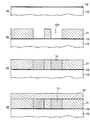
次の工程では(図6(a)参照)、樹脂基板12及び配線層14(「基板パッド」部分14a、「下配線」部分14b)の表面を覆って全面に保護膜として供される絶縁層16を形成する。この絶縁層16の材料としては、例えば、プリント配線板等において多く用いられているソルダレジスト(エポキシアクリレート樹脂やエポキシ樹脂の部分アクリル化樹脂など)を使用することができる。なお、図示の例では、樹脂基板12上に直接「下配線」部分14bが形成されているが、実際には、「下配線」部分14bが形成されている部分については樹脂基板12上のシード層13(図5(a)参照)は残存しており、このシード層13については図示を省略している。この段階では、図6(a)の上側の断面図に示すように、基板パッド14a上にも絶縁層16の一部分(樹脂)が若干堆積し、当該部分の断面が凸形状を呈するため、基板の表面は凹凸状態にある。
In the next step (see FIG. 6A), an insulating layer that covers the surfaces of the
最後の工程では(図6(b)参照)、絶縁層16を研磨して「基板パッド」部分14aの上面を露出させると共に、基板の表面全体を平坦化(平滑化)する。
In the last step (see FIG. 6B), the insulating
ここでは、研磨の対象は金属ではなく樹脂(絶縁層16)であるため、研磨方法としては、薬液を用いて行う化学研磨よりも、研磨紙や研磨材を含むバフやブラシ、振動などを利用して行う機械研磨の方が望ましい。例えば、バフ研磨の場合、研磨材を埋め込んだ円筒状のバフ及び研磨対象表面(絶縁層16の表面)を冷却水で湿潤させながら、バフを回転させて研磨対象表面に押し当てて研磨を行い、「基板パッド」部分14aの上面が露出した時点で研磨を止める。これにより、図示のように「基板パッド」部分14aの上面と基板の表面(絶縁層16の表面)が同一面上で平坦化される。バフ研磨以外にも、スクラブ研磨やサンドブラストなど、必要に応じて他の機械研磨を行ってもよい。
Here, since the object of polishing is not a metal but a resin (insulating layer 16), the polishing method uses a buff or brush containing abrasive paper or an abrasive, vibration, etc., rather than chemical polishing performed using a chemical solution. Thus, mechanical polishing is preferable. For example, in the case of buffing, the cylindrical buff and the polishing target surface (the surface of the insulating layer 16) embedded with an abrasive are wetted with cooling water, and the buff is rotated and pressed against the polishing target surface for polishing. The polishing is stopped when the upper surface of the “substrate pad”
以上説明したように、本実施形態に係る配線基板10(図2)及びその製造方法(図3〜図6)によれば、基板パッド14aの上面は配線基板10の表面(絶縁層16の表面)と同一面上に位置するので、基板パッド14aの側面は外部に露出せず、その上面のみが露出する。これに対し、従来の技術(図1)では基板パッド3の側面も露出していた。
As described above, according to the wiring board 10 (FIG. 2) and the manufacturing method thereof (FIGS. 3 to 6) according to the present embodiment, the upper surface of the
従って、フリップチップ接続のためのはんだを基板パッドに被着させる際にはんだ粉を基板パッドの表面に吸着させると、本配線基板10の表面には凹凸の段差がない(平坦化されている)ため、図7(a)に例示するように、基板パッド14aの上面にのみはんだ粉30を吸着させることができる。これにより、従来技術(図1(a))に見られたような隣接する基板パッド3(その対向する側面)上のはんだ粉4同士のショートもしくはブリッジの発生要因を実質的に無くすことができる。
Therefore, when the solder powder is adsorbed on the surface of the substrate pad when the solder for flip chip connection is applied to the substrate pad, there is no uneven step on the surface of the wiring substrate 10 (flattened). Therefore, as illustrated in FIG. 7A, the
また、本配線基板10に半導体チップをフリップチップ接続した後に両者間にアンダーフィル樹脂を充填する際にも、基板パッド14aと基板表面が同一面にあるので、基板パッド14aのピッチが狭くなっている場合でも、アンダーフィル樹脂を比較的スムーズに流動させることができ(流動性の均一化)、樹脂が内部に入り易くなる。これにより、従来技術(図1(b))に見られたようなボイドVDの発生や充填不足といった不良発生要因を大いに減らす(実質的に無くす)ことができる。このことは、客先(本配線基板10にチップを搭載するメーカなど)での歩留り改善に大いに寄与する。
Also, when a semiconductor chip is flip-chip connected to the
図7(b)はフリップチップ実装後の半導体装置の一例を示したものであり、本配線基板10(基板パッド14a)に半導体素子40(チップパッド41)をはんだバンプ31を介してフリップチップ接続した後、チップ40と配線基板10の間にアンダーフィル樹脂32(例えば、エポキシ系樹脂やアクリル系樹脂等の熱硬化性樹脂)を充填した状態を示している。なお、図7(b)には示していないが、配線基板10の裏面(チップ搭載面側と反対側の面)にも、配線層のパッド部分を除いて全面(裏面)を覆うようにソルダレジスト等からなる絶縁層が形成されており、この絶縁層から露出するパッド部分に、半導体装置の外部接続端子として機能する金属ボールや金属ピン等がはんだを介して接合されている。
FIG. 7B shows an example of a semiconductor device after flip-chip mounting. The semiconductor element 40 (chip pad 41) is flip-chip connected to the wiring board 10 (
上述した実施形態では、図3(c)の工程において配線層14を「厚付け配線めっき」により一括して形成する場合を例にとって説明したが、配線層14の形成方法はこれに限定されないことはもちろんである。例えば、後の工程(図5(a))で「基板パッド」部分14a以外の配線部分を「必要量」エッチングすることを考慮すると、この「必要量」をより確実に制御できるようにするために、「下配線」部分14bと「基板パッド」部分14aの2段に分けて配線層を形成するようにしてもよい。その場合の処理工程の一例を図8に示す。
In the above-described embodiment, the case where the
図8において、先ず、上述した図3(b)の工程で行った処理と同様にして、樹脂基板12(導体層13)上に所要の配線パターンの形状に応じたレジスト層21を25μm程度の厚さに形成し(図8(a)参照)、次に、レジスト層21の開口部OPから露出しているシード層(Cu)13を給電層として電解銅(Cu)めっきを施し、開口部OP内を15μm程度埋め込むようにして「下配線」部分14bを形成する(図8(b)参照)。さらに、「下配線」部分14bを形成した時の電解めっきの条件と異なる条件(例えば、めっき液を変えたり、印加する電源電圧を直流(DC)方式から交流(AC)方式あるいはパルス方式に変えるなど)の下に、「下配線」部分14bに電解銅(Cu)めっきを施し、開口部OP内の残りの部分(10μm程度)を埋め込むようにして「基板パッド」部分14aを形成する(図8(c)参照)。そして、図3(d)の工程で行った処理と同様にして、全面にレジスト層22を形成する(図8(d)参照)。
In FIG. 8, first, in the same manner as the process performed in the process of FIG. 3B described above, a resist
この実施形態によれば、上述した実施形態に係る製造方法と比べて、配線層を形成するための工程を2回に分けているため工程数が1つ増えるものの、「下配線」部分14bと「基板パッド」部分14aとで電解めっきの条件を変えているので、各部分のめっき配線の結晶配向を変えることができる(つまり、各部分のエッチングレートを異ならせることができる)。これにより、後の工程(図5(a))で「基板パッド」部分14a以外の配線部分を「必要量」エッチングする際に、各部分のめっき配線の結晶配向(エッチングレート)の違いにより、その「必要量」の厚さ、すなわち、「基板パッド」部分14aの厚さと「下配線」部分14bの厚さをより確実に制御することができる。
According to this embodiment, compared with the manufacturing method according to the above-described embodiment, the number of processes is increased by dividing the process for forming the wiring layer into two times, but the “lower wiring”
図8に示した実施形態では、「下配線」になる部分14bと「基板パッド」になる部分14aとに分けてそれぞれ銅(Cu)めっき配線の結晶配向を変えることで各部分のエッチングレートを異ならせるようにしたが、この方法以外にも、例えば、各部分のめっき配線間に中間金属層(バリヤメタル)を形成するようにしてもよい。この方法では、「下配線」になる部分14bの銅(Cu)めっき配線を形成した後、このめっき配線上に、例えば、ニッケル(Ni)めっき及び金(Au)めっきを施して2層構造(Ni/Au)のバリヤメタル層を形成し、更にこのバリヤメタル層上に、「基板パッド」になる部分14aの銅(Cu)めっき配線を形成する。
In the embodiment shown in FIG. 8, the etching rate of each part is changed by changing the crystal orientation of the copper (Cu) plating wiring separately into the
この実施形態では、バリヤメタル層とめっき配線のエッチングレートが異なるため、図5(a)の工程で「基板パッド」部分14a以外の配線部分を「必要量」エッチングする際に、バリヤメタル層はそのエッチングのストッパ層として機能する。これにより、上記の実施形態の場合と同様に、「基板パッド」部分14aの厚さと「下配線」部分14bの厚さをより確実に制御することができる。
In this embodiment, since the etching rate of the barrier metal layer and the plated wiring is different, when the wiring portion other than the “substrate pad”
10…配線基板(フリップチップ実装用基板)、
12…樹脂基板、
13…シード層(導体層)、
14…配線層、
14a…基板パッド(配線層の「基板パッド」部分)、
14b…下配線(配線層の「下配線」部分)、
16…ソルダレジスト層(絶縁層/保護膜)、
21,22,22a…レジスト層、
30…はんだ粉、
31…はんだバンプ、
32…アンダーフィル樹脂、
40…半導体素子(チップ)、
41…電極端子(チップパッド)、
SP…隣接する基板パッド(側面)上のはんだ粉同士がショートしている部分、
VD…ボイド(空洞部分)。
10: Wiring board (flip chip mounting board),
12 ... Resin substrate,
13 ... Seed layer (conductor layer),
14 ... wiring layer,
14a ... substrate pad ("substrate pad" portion of the wiring layer),
14b ... lower wiring ("lower wiring" part of the wiring layer),
16 ... Solder resist layer (insulating layer / protective film),
21, 22, 22a... Resist layer,
30 ... solder powder,
31 ... Solder bump,
32. Underfill resin,
40: Semiconductor element (chip),
41 ... Electrode terminal (chip pad),
SP: The part where the solder powder on the adjacent board pad (side surface) is short-circuited,
VD: Void (cavity).
Claims (6)
前記配線層は、配線部分を構成する第1のめっき配線の一部領域上にのみ、前記パッド部分を構成する、前記第1のめっき配線と結晶配向が異なる第2のめっき配線が積み重ねられた構造を有し、前記パッド部分の上面が前記絶縁層の表面と同一面上に位置するように形成されていることを特徴とする配線基板。 A wiring layer including a flip chip connecting pad portion formed on a substrate as a base material; and an insulating layer formed so as to cover only the pad portion and cover the substrate and the wiring layer. ,
The wiring layer is formed by stacking a second plating wiring having a crystal orientation different from that of the first plating wiring constituting the pad portion only on a partial region of the first plating wiring constituting the wiring portion. A wiring board having a structure, wherein the pad portion is formed such that an upper surface of the pad portion is located on the same plane as the surface of the insulating layer.
前記第1のレジスト層の開口部から露出している前記導体層を給電層として電解めっきを施し、当該開口部内を部分的に埋め込むように第1の配線層を形成する工程と、
電解めっきの条件を変えて前記第1の配線層に電解めっきを施し、当該開口部内の残りの部分を埋め込むように前記第1の配線層と結晶配向が異なる第2の配線層を形成する工程と、
前記第2の配線層のパッド部分に対応する領域にパターンが残るように、前記第1のレジスト層及び前記第2の配線層の上に第2のレジスト層を形成する工程と、
前記第2のレジスト層をマスクにして、前記第2の配線層の露出している部分のみをエッチングすることで、前記第1の配線層を露出させる工程と、
前記第2のレジスト層及び第1のレジスト層を除去した後、前記基板及び前記第1、第2の配線層を覆って全面に絶縁層を形成する工程と、
前記絶縁層を研磨して前記パッド部分の上面を露出させると共に、基板表面全体を平坦化する工程とを含むことを特徴とする配線基板の製造方法。 A first resist layer having an opening patterned according to the shape of a required wiring layer including a pad portion for connecting a flip chip to be formed on at least one surface of a substrate having a conductor layer formed on at least the outermost layer. Forming, and
Performing electroplating using the conductor layer exposed from the opening of the first resist layer as a power feeding layer, and forming a first wiring layer so as to partially bury the inside of the opening;
The step of subjecting the first wiring layer to electrolytic plating under different electrolytic plating conditions and forming a second wiring layer having a crystal orientation different from that of the first wiring layer so as to embed the remaining portion in the opening. When,
Forming a second resist layer on the first resist layer and the second wiring layer so that a pattern remains in a region corresponding to a pad portion of the second wiring layer ;
Using the second resist layer as a mask, etching only the exposed portion of the second wiring layer, thereby exposing the first wiring layer;
Forming an insulating layer over the entire surface covering the substrate and the first and second wiring layers after removing the second resist layer and the first resist layer;
Polishing the insulating layer to expose the upper surface of the pad portion and planarizing the entire substrate surface.
前記第1の配線層上にバリヤメタル層を形成し、さらに該バリヤメタル層に電解めっきを施し、当該開口部内の残りの部分を埋め込むように第2の配線層を形成する工程を含むことを特徴とする請求項2に記載の配線基板の製造方法。 Instead of changing the electrolytic plating conditions and forming the second wiring layer,
Forming a barrier metal layer on the first wiring layer, further subjecting the barrier metal layer to electrolytic plating, and forming a second wiring layer so as to embed the remaining portion in the opening. A method for manufacturing a wiring board according to claim 2.
Priority Applications (1)
| Application Number | Priority Date | Filing Date | Title |
|---|---|---|---|
| JP2006308322A JP5069449B2 (en) | 2006-11-14 | 2006-11-14 | Wiring board and manufacturing method thereof |
Applications Claiming Priority (1)
| Application Number | Priority Date | Filing Date | Title |
|---|---|---|---|
| JP2006308322A JP5069449B2 (en) | 2006-11-14 | 2006-11-14 | Wiring board and manufacturing method thereof |
Publications (3)
| Publication Number | Publication Date |
|---|---|
| JP2008124339A JP2008124339A (en) | 2008-05-29 |
| JP2008124339A5 JP2008124339A5 (en) | 2009-11-05 |
| JP5069449B2 true JP5069449B2 (en) | 2012-11-07 |
Family
ID=39508751
Family Applications (1)
| Application Number | Title | Priority Date | Filing Date |
|---|---|---|---|
| JP2006308322A Active JP5069449B2 (en) | 2006-11-14 | 2006-11-14 | Wiring board and manufacturing method thereof |
Country Status (1)
| Country | Link |
|---|---|
| JP (1) | JP5069449B2 (en) |
Families Citing this family (6)
| Publication number | Priority date | Publication date | Assignee | Title |
|---|---|---|---|---|
| KR20110038521A (en) * | 2009-10-08 | 2011-04-14 | 엘지이노텍 주식회사 | Printed circuit board and manufacturing method of the same |
| US10388608B2 (en) * | 2015-08-28 | 2019-08-20 | Hitachi Chemical Company, Ltd. | Semiconductor device and method for manufacturing same |
| JP7048593B2 (en) * | 2017-05-19 | 2022-04-05 | ベジ 佐々木 | Substrate for mounting electronic components and its manufacturing method |
| TWI705747B (en) * | 2019-08-30 | 2020-09-21 | 嘉聯益科技股份有限公司 | Multilayer flexible circuit board and manufacturing method thereof |
| TWI831123B (en) * | 2022-01-28 | 2024-02-01 | 巨擘科技股份有限公司 | Surface finish structure of multi-layer substrate |
| CN115190701B (en) * | 2022-05-13 | 2023-06-02 | 广州广芯封装基板有限公司 | Embedded circuit packaging substrate and processing method thereof |
Family Cites Families (6)
| Publication number | Priority date | Publication date | Assignee | Title |
|---|---|---|---|---|
| JPH03253091A (en) * | 1990-03-02 | 1991-11-12 | Tokuyama Soda Co Ltd | Manufacture of printed wiring board |
| JPH11126974A (en) * | 1997-10-24 | 1999-05-11 | Asahi Chem Res Lab Ltd | Manufacture of multilayered wiring board |
| JP2002299779A (en) * | 2001-03-30 | 2002-10-11 | Hitachi Metals Ltd | Wiring-forming strip material, wiring substrate having bump-containing wiring using the same, and method for manufacturing transfer wiring substrate using the wiring-forming strip material |
| JP2003008228A (en) * | 2001-06-22 | 2003-01-10 | Ibiden Co Ltd | Multilayer printed wiring board and method of manufacturing the same |
| JP2004095972A (en) * | 2002-09-03 | 2004-03-25 | Sumitomo Metal Electronics Devices Inc | Manufacturing method for plastic package |
| JP2005166910A (en) * | 2003-12-02 | 2005-06-23 | Fujikura Ltd | Printed wiring board and its manufacturing method |
-
2006
- 2006-11-14 JP JP2006308322A patent/JP5069449B2/en active Active
Also Published As
| Publication number | Publication date |
|---|---|
| JP2008124339A (en) | 2008-05-29 |
Similar Documents
| Publication | Publication Date | Title |
|---|---|---|
| TWI471956B (en) | Semiconductor package and fabrication method | |
| JP5113114B2 (en) | Wiring board manufacturing method and wiring board | |
| KR101551898B1 (en) | Wiring board semiconductor apparatus and method of manufacturing them | |
| US9681546B2 (en) | Wiring substrate and semiconductor device | |
| JP5886617B2 (en) | Wiring substrate, manufacturing method thereof, and semiconductor package | |
| US8304663B2 (en) | Wiring board and manufacturing method thereof | |
| JP6661232B2 (en) | Wiring substrate, semiconductor device, method of manufacturing wiring substrate, and method of manufacturing semiconductor device | |
| WO2011089936A1 (en) | Substrate with built-in functional element, and wiring substrate | |
| JP5091469B2 (en) | Wiring board and manufacturing method thereof | |
| JPWO2004103039A1 (en) | Double-sided wiring board and method for manufacturing double-sided wiring board | |
| JPWO2007126090A1 (en) | CIRCUIT BOARD, ELECTRONIC DEVICE DEVICE, AND CIRCUIT BOARD MANUFACTURING METHOD | |
| US9997474B2 (en) | Wiring board and semiconductor device | |
| US9935053B2 (en) | Electronic component integrated substrate | |
| JP2017073520A (en) | Wiring board, semiconductor device, and manufacturing method of wiring board | |
| JP5069449B2 (en) | Wiring board and manufacturing method thereof | |
| WO2004014114A1 (en) | Method for manufacturing board with built-in device and board with built-in device, and method for manufacturing printed wiring board and printed wiring board | |
| JP7253946B2 (en) | Wiring board and its manufacturing method, semiconductor package | |
| JP2015159197A (en) | Wiring board and method for manufacturing the same | |
| JP4170266B2 (en) | Wiring board manufacturing method | |
| JP4835629B2 (en) | Manufacturing method of semiconductor device | |
| TWI771573B (en) | Wiring board, semiconductor device, and manufacturing method of wiring board | |
| JP5599860B2 (en) | Manufacturing method of semiconductor package substrate | |
| JP2007158069A (en) | External connection structure for semiconductor package and manufacturing method thereof | |
| JP2004200412A (en) | Wiring board with solder bump, and manufacturing method thereof | |
| JP2004356219A (en) | Wiring board and its manufacturing method |
Legal Events
| Date | Code | Title | Description |
|---|---|---|---|
| A521 | Written amendment |
Free format text: JAPANESE INTERMEDIATE CODE: A523 Effective date: 20090916 |
|
| A621 | Written request for application examination |
Free format text: JAPANESE INTERMEDIATE CODE: A621 Effective date: 20090916 |
|
| A977 | Report on retrieval |
Free format text: JAPANESE INTERMEDIATE CODE: A971007 Effective date: 20110719 |
|
| A131 | Notification of reasons for refusal |
Free format text: JAPANESE INTERMEDIATE CODE: A131 Effective date: 20110927 |
|
| A521 | Written amendment |
Free format text: JAPANESE INTERMEDIATE CODE: A523 Effective date: 20111128 |
|
| A131 | Notification of reasons for refusal |
Free format text: JAPANESE INTERMEDIATE CODE: A131 Effective date: 20120605 |
|
| A521 | Written amendment |
Free format text: JAPANESE INTERMEDIATE CODE: A523 Effective date: 20120712 |
|
| TRDD | Decision of grant or rejection written | ||
| A01 | Written decision to grant a patent or to grant a registration (utility model) |
Free format text: JAPANESE INTERMEDIATE CODE: A01 Effective date: 20120814 |
|
| A01 | Written decision to grant a patent or to grant a registration (utility model) |
Free format text: JAPANESE INTERMEDIATE CODE: A01 |
|
| A61 | First payment of annual fees (during grant procedure) |
Free format text: JAPANESE INTERMEDIATE CODE: A61 Effective date: 20120817 |
|
| FPAY | Renewal fee payment (event date is renewal date of database) |
Free format text: PAYMENT UNTIL: 20150824 Year of fee payment: 3 |
|
| R150 | Certificate of patent or registration of utility model |
Ref document number: 5069449 Country of ref document: JP Free format text: JAPANESE INTERMEDIATE CODE: R150 Free format text: JAPANESE INTERMEDIATE CODE: R150 |