JP5055552B2 - Slot machine - Google Patents
Slot machine Download PDFInfo
- Publication number
- JP5055552B2 JP5055552B2 JP2007225231A JP2007225231A JP5055552B2 JP 5055552 B2 JP5055552 B2 JP 5055552B2 JP 2007225231 A JP2007225231 A JP 2007225231A JP 2007225231 A JP2007225231 A JP 2007225231A JP 5055552 B2 JP5055552 B2 JP 5055552B2
- Authority
- JP
- Japan
- Prior art keywords
- cover member
- operation means
- front door
- input
- variable display
- Prior art date
- Legal status (The legal status is an assumption and is not a legal conclusion. Google has not performed a legal analysis and makes no representation as to the accuracy of the status listed.)
- Expired - Fee Related
Links
- 238000003860 storage Methods 0.000 claims description 16
- 239000000758 substrate Substances 0.000 claims description 8
- 230000002093 peripheral effect Effects 0.000 claims description 7
- 238000003780 insertion Methods 0.000 description 6
- 230000037431 insertion Effects 0.000 description 6
- 230000008859 change Effects 0.000 description 5
- 238000001514 detection method Methods 0.000 description 5
- 238000003825 pressing Methods 0.000 description 5
- 238000005192 partition Methods 0.000 description 4
- 238000000034 method Methods 0.000 description 3
- 239000011347 resin Substances 0.000 description 3
- 229920005989 resin Polymers 0.000 description 3
- 238000005034 decoration Methods 0.000 description 2
- 230000000694 effects Effects 0.000 description 2
- 238000005516 engineering process Methods 0.000 description 2
- 239000000463 material Substances 0.000 description 2
- 230000004048 modification Effects 0.000 description 2
- 238000012986 modification Methods 0.000 description 2
- 230000000630 rising effect Effects 0.000 description 2
- 241000167854 Bourreria succulenta Species 0.000 description 1
- 241000219109 Citrullus Species 0.000 description 1
- 235000012828 Citrullus lanatus var citroides Nutrition 0.000 description 1
- 230000007175 bidirectional communication Effects 0.000 description 1
- 235000019693 cherries Nutrition 0.000 description 1
- 238000002788 crimping Methods 0.000 description 1
- 238000005520 cutting process Methods 0.000 description 1
- 230000008030 elimination Effects 0.000 description 1
- 238000003379 elimination reaction Methods 0.000 description 1
- 230000006870 function Effects 0.000 description 1
- 239000011159 matrix material Substances 0.000 description 1
- 230000002265 prevention Effects 0.000 description 1
- 230000008569 process Effects 0.000 description 1
- 230000004044 response Effects 0.000 description 1
Images


Landscapes
- Slot Machines And Peripheral Devices (AREA)
Description
本発明は、前面が開放した箱形の筐体と、この筐体前面に開閉可能に軸着された前面扉と、複数の図柄を外周面に表示された複数のリールを備え、リールを回転させることにより可変表示ゲームを行う変動表示手段と、前記変動表示手段による可変表示ゲームを実行するための賭入力手段と、前記賭入力手段による賭入力の後、可変表示ゲームを開始するためのスタート操作手段と、前記賭入力手段及び前記スタート操作手段からの出力信号に基づいて、可変表示ゲームに関する制御を行う遊技制御手段と、前記賭入力手段及び前記スタート操作手段からの出力信号を集約し、配線接続部を介して前記出力信号を前記遊技制御手段に出力する中継基板と、を備え、前記賭入力手段による賭入力を条件に、その後の前記スタート操作手段の操作に基づいて可変表示ゲームを実行し、該可変表示ゲームの結果に関連して遊技者に所定の遊技価値を付与するスロットマシンに関する。 The present invention includes a box-shaped housing having an open front surface, a front door pivotally attached to the front surface of the housing, and a plurality of reels each having a plurality of symbols displayed on an outer peripheral surface thereof. A variable display game for performing a variable display game, a bet input unit for executing the variable display game by the variable display unit, and a start for starting the variable display game after a bet input by the bet input unit Based on the output signals from the operation means, the bet input means and the start operation means, the game control means for controlling the variable display game, the output signals from the bet input means and the start operation means are aggregated, A relay board for outputting the output signal to the game control means via a wiring connection portion, and a subsequent operation of the start operation means on condition of betting input by the betting input means. Based perform the variable display games, about the slot machine that applies a predetermined game value to the player in relation to the result of the variable display game.
従来、複数の図柄を外周面に表示した複数(例えば、3個)のリールを備え、これらのリールを回転させることで複数の図柄を変動表示させる可変表示ゲームを行い、可変表示ゲームの結果、予め設定された有効ライン上において所定の図柄組合せ態様が形成された場合に、所定の遊技価値を遊技者に付与するようにしたスロットマシンが一般的に知られている。 Conventionally, a variable display game in which a plurality of (for example, three) reels having a plurality of symbols displayed on the outer peripheral surface is provided and the plurality of symbols are variably displayed by rotating these reels is performed. 2. Description of the Related Art A slot machine is generally known in which a predetermined game value is given to a player when a predetermined symbol combination form is formed on a preset active line.
スロットマシンにおいては、遊技者による所定数(通常1〜3枚)の遊技媒体(メダルや遊技球)の投入操作、あるいはクレジットからの賭けボタン操作(ベット操作)に基づく賭入力の後、スタートレバーが操作されることにより可変表示ーゲームが開始される。そして、一定時間経過後に自動的に、又は遊技者が各リールに対応して各々設けられたリール停止ボタンを操作することにより、各リールの回転を順次停止させて図柄組合せ態様(停止表示態様)が確定される。
リールが停止した際に、前記賭入力に応じて有効化された有効ライン上に形成された図柄組合せ態様が、予め定められた所定の図柄組合せ態様(入賞態様)となった場合に入賞が確定(成立)し、入賞種類に対応した数の遊技媒体が遊技者に付与される。
ここで、遊技者が遊技を開始するために遊技媒体を投入することおよび予めスロットマシンに預け入れた(クレジット)遊技媒体の記憶数から賭けボタン操作に応じてクレジット数を減算することに基づく賭数の入力を総称してベットまたは賭入力と呼ぶ。
In a slot machine, after a betting input based on a predetermined number (usually 1 to 3) of game media (medals or game balls) input by a player or a bet button operation (bet operation) from a credit, a start lever Is operated, the variable display game is started. Then, after a predetermined time has elapsed, or by operating a reel stop button provided corresponding to each reel by the player, the rotation of each reel is sequentially stopped, and the symbol combination mode (stop display mode) Is confirmed.
When the reels are stopped, the winning combination is confirmed when the symbol combination form formed on the activated line activated in response to the betting input becomes a predetermined symbol combination aspect (winning aspect) set in advance. (Established), the number of game media corresponding to the winning type is awarded to the player.
Here, the number of bets based on the player inserting a game medium to start the game and subtracting the credit number in accordance with the betting button operation from the stored number of (credit) game medium deposited in the slot machine in advance. Are collectively referred to as a bet or bet input.
つまり、スロットマシンでは、遊技者によって賭入力が行われたことを示す信号、スタートレバーが操作されたことを示す信号に基づいて、遊技制御装置が可変表示ゲームに関する制御を行う。 That is, in the slot machine, the game control device performs control related to the variable display game based on a signal indicating that a bet input has been performed by the player and a signal indicating that the start lever has been operated.
一方、スロットマシンに接続して使用することにより、スロットマシン本来の遊技方法以外の電気信号を送信するなどの方法で、遊技制御装置に内部抽選を行わせる機能を有する、いわゆる「打ち込み機」が知られている。この打ち込み機は、本来、遊技媒体を投入することで出力されるべき出力信号、スタートレバー及びリールストップボタン等の操作部から出力されるべき出力信号、或いは、クレジットがある状態でベットボタンから出力されるべき出力信号を、打ち込み機から遊技制御装置に出力することにより、自動的にゲームを進行させることができる。 On the other hand, there is a so-called “driving machine” that has a function of causing the game control device to perform an internal lottery by a method such as transmitting an electrical signal other than the original gaming method by connecting to the slot machine. Are known. This driving machine originally outputs an output signal to be output by inserting a game medium, an output signal to be output from an operation unit such as a start lever and a reel stop button, or an output from a bet button in the presence of credit. By outputting an output signal to be played from the driving machine to the game control device, the game can be automatically advanced.
従来のスロットマシンでは、メダルが投入されたことを検出するメダル検出センサや、スタートレバー、リールストップボタン、及びベットボタン等の操作部からの配線コネクタが中継基板の基板コネクタに接続されており、これらから出力された信号は中継基板に集約される。そして、この出力信号は、中継基板にコネクタ接続された遊技制御装置に送信される構成となっている。このため、例えば遊技制御装置と中継基板とのコネクタ接続を解除し、遊技制御装置からの配線コネクタに打ち込み機のコネクタを接続することで、スロットマシンに打ち込み機を容易に取り付けることができる。なお、基板コネクタとは中継基板等の基板側に設けられるコネクタであり、配線コネクタとは配線の端部に設けられるコネクタである。 In a conventional slot machine, a medal detection sensor that detects that a medal has been inserted, and a wiring connector from an operation unit such as a start lever, a reel stop button, and a bet button are connected to the board connector of the relay board, The signals output from these are collected on the relay board. The output signal is transmitted to the game control device connected to the relay board by a connector. Therefore, for example, by releasing the connector connection between the game control device and the relay board and connecting the connector of the driving machine to the wiring connector from the game control device, the driving machine can be easily attached to the slot machine. The board connector is a connector provided on a board side such as a relay board, and the wiring connector is a connector provided at an end of the wiring.
例えば、遊技店において、開店時に遊技者が有利な状態(予めボーナス入賞フラグが成立した状態)で遊技を開始できるようにする、いわゆるモーニングサービスを提供するために打ち込み機が使用される。 For example, in a game store, a driving machine is used to provide a so-called morning service that allows a player to start a game in an advantageous state (a state in which a bonus winning flag has been established in advance) when the store is opened.
しかしながら、打ち込み機の使用は、遊技機の性能に影響を及ぼすおそれのある変更に該当するために違法とされている。そして、打ち込み機を使用した不正改造事犯の取り締まりが強化され、同種事犯の防止が強く要求されている。 However, the use of a driving machine is illegal because it corresponds to a change that may affect the performance of the gaming machine. And the control of illegal modification crimes using a driving machine has been strengthened, and the prevention of similar crimes is strongly demanded.
上述した要求に応える技術として、遊技機の電源オフ後に、所定時間経過でRAMをクリアするようにした遊技機が開示されている(例えば、特許文献1)。かかる技術によれば、遊技店において、閉店後に打ち込み機を使用してボーナス入賞フラグが成立した状態としても、電源オフ後に所定時間経過するとボーナス入賞フラグはクリアされるため、打ち込み機を有効に使用するのが困難となる。
しかしながら、特許文献1に記載の遊技機であっても、遊技店が開店前(フラグがクリアされるまでの時間以内)に打ち込み機を使用すれば、ボーナス入賞フラグを成立させた状態で遊技者に遊技を開始させることができる。つまり、打ち込み機を使用できる時間帯が制限されるだけであり、打ち込み機の使用を確実に防止できるわけではない。
However, even in the gaming machine described in
本発明は、中継基板の配線接続部(コネクタ部)を含む操作部周りの構成を改善することにより、打ち込み機等の不正機器の使用を確実に防止できるスロットマシンを提供することを目的とする。 It is an object of the present invention to provide a slot machine that can reliably prevent the use of unauthorized equipment such as a driving machine by improving the configuration around the operation section including the wiring connection section (connector section) of the relay board. .
上記目的を達成するため、請求項1に記載の発明は、
前面が開放した箱形の筐体と、
この筐体前面に開閉可能に軸着された前面扉と、
複数の図柄を外周面に表示された複数のリールを備え、リールを回転させることにより可変表示ゲームを行う変動表示手段と、
前記変動表示手段による可変表示ゲームを実行するための賭入力手段と、
前記賭入力手段による賭入力の後、可変表示ゲームを開始するためのスタート操作手段と、
前記賭入力手段及び前記スタート操作手段からの出力信号に基づいて、可変表示ゲームに関する制御を行う遊技制御手段と、
前記賭入力手段及び前記スタート操作手段からの出力信号を集約し、配線接続部を介して前記出力信号を前記遊技制御手段に出力する中継基板と、を備え、
前記賭入力手段による賭入力を条件に、その後の前記スタート操作手段の操作に基づいて可変表示ゲームを実行し、該可変表示ゲームの結果に関連して遊技者に所定の遊技価値を付与するスロットマシンにおいて、
前記スタート操作手段は、前記前面扉の前面側に操作部が露呈されるとともに、裏面側で前記中継基板に接続されるように配設され、
前記賭入力手段は、クレジットから賭入力を行うための賭入力操作手段を含み、
前記前面扉には、
前記スタート操作手段の裏面側を覆う第1カバー部材と、
前記第1カバー部材及び前記中継基板を覆う第2カバー部材と、が設けられ、
前記第1カバー部材は、前記賭入力操作手段の裏面側を覆い、前記賭入力操作手段を収納する第1収納部と、前記スタート操作手段を収納する第2収納部を有し、
前記第2収納部には、前記スタート操作手段を前記前面扉に固着するためのネジを挿通する貫通孔が設けられるとともに、前記ネジの取付作業を行うための開口部が後方に向けて形成され、
前記スタート操作手段及び前記第1カバー部材は、当該第1カバー部材の後方開口部から前記貫通孔を介してネジ留めされることにより前記前面扉に取り付けられ、
前記第2カバー部材は、前記第1カバー部材に外接してカシメ部材を用いて前記前面扉に着脱不能に取り付けられることを特徴とする。
In order to achieve the above object, the invention described in
A box-shaped housing with an open front,
A front door pivotably attached to the front of the housing;
Fluctuation display means comprising a plurality of reels having a plurality of symbols displayed on the outer peripheral surface and performing a variable display game by rotating the reels;
Betting input means for executing a variable display game by the variable display means;
After the betting input by the betting input means, start operation means for starting a variable display game;
Game control means for controlling the variable display game based on output signals from the betting input means and the start operation means;
A relay board that aggregates output signals from the betting input means and the start operation means and outputs the output signals to the game control means via a wiring connection unit;
A slot for executing a variable display game based on a subsequent operation of the start operation means on the condition of a bet input by the bet input means and giving a predetermined game value to a player in relation to the result of the variable display game In the machine
The start operation means is arranged so that the operation unit is exposed on the front side of the front door and connected to the relay board on the back side,
The betting input means includes betting input operation means for inputting betting from credits,
In the front door,
A first cover member covering the back side of the start operation means;
A second cover member that covers the first cover member and the relay substrate;
The first cover member covers a back side of the betting input operation means, and has a first storage portion for storing the betting input operation means, and a second storage portion for storing the start operation means,
The second storage portion is provided with a through-hole through which a screw for fixing the start operation means to the front door is inserted, and an opening for performing the screw mounting operation is formed rearward. ,
The start operation means and the first cover member are attached to the front door by being screwed from the rear opening of the first cover member through the through hole,
The second cover member may be attached to the front door in a non-detachable manner using a caulking member that circumscribes the first cover member .
ここで、「賭入力手段」とは、予め設定されたクレジットから賭入力を行うベットボタンや、遊技媒体が投入されたことを検出するメダル検出センサを含む。
また、「配線接続部」とは、賭入力手段、スタート操作手段、又は遊技制御手段からの配線コネクタが接続される基板側のコネクタ(基板コネクタ)である。
また、「カシメ部材」とは、破壊しない限り解除できない止着部材であり、「着脱不能に取り付けられる」とは、取り外しが極めて困難な状態で取り付けられること、すなわち着脱自在ではないことを意味する。例えば、カシメ部材を破壊することにより第2カバー部材を取り外すことは可能である。
Here, the “betting input means” includes a betting button for inputting a betting from a preset credit and a medal detection sensor for detecting that a gaming medium is inserted.
The “wiring connection section” is a board-side connector (board connector) to which a wiring connector from the betting input means, the start operation means, or the game control means is connected.
Further, the “crimping member” is a fastening member that cannot be released unless it is broken, and “attached in a non-detachable manner” means that it is attached in a state where it is extremely difficult to remove, that is, it is not removable. . For example, it is possible to remove the second cover member by destroying the caulking member.
請求項1に記載の発明によれば、第2カバー部材を取り外さない限り、賭入力手段及びスタート操作手段からの配線コネクタを接続する基板コネクタは外部に露呈されないので、中継基板上の基板コネクタに打ち込み機の配線コネクタが接続されるのを防止できる。
また、第2カバー部材を取り外さない限り、遊技制御装置からの配線コネクタを、中継基板上の基板コネクタから取り外すことが困難となるので、遊技制御装置からの配線コネクタに打ち込み機のコネクタが接続されるのを防止できる。
さらに、第1カバー部材を取り外さない限り、中継基板からの配線コネクタをスタート操作手段側のコネクタ及び賭入力操作手段側のコネクタから取り外すことが困難となるので、この配線コネクタに打ち込み機のコネクタが接続されるのを防止でき、打ち込み機によるクレジットからの賭入力を防止できる。したがって、コネクタ接続により打ち込み機をスロットマシンに簡単に取り付けることはできないので、打ち込み機等の不正機器の使用を防止することができる。
さらに、第2カバー部材は、第1カバー部材に外接するように前面扉に取り付けられ、第1カバー部材に覆われた賭入力操作手段及びスタート操作手段は外部空間と遮断されることとなるので、賭入力操作手段及びスタート操作手段からの配線を改変することも困難となり、より厳重に不正機器の使用を防止することができる。
According to the first aspect of the present invention, the board connector for connecting the wiring connector from the betting input means and the start operation means is not exposed to the outside unless the second cover member is removed. It is possible to prevent the wiring connector of the driving machine from being connected.
Further, unless the second cover member is removed, it is difficult to remove the wiring connector from the game control device from the board connector on the relay board, so the connector of the driving machine is connected to the wiring connector from the game control device. Can be prevented.
Furthermore, unless the first cover member is removed, it is difficult to remove the wiring connector from the relay board from the connector on the start operation means side and the connector on the betting input operation means side. can be prevented from being connected, Ru can be prevented bets input from the credit by the driving machine. Therefore, since the driving machine cannot be easily attached to the slot machine by the connector connection, it is possible to prevent the use of unauthorized equipment such as a driving machine.
Further, the second cover member is attached to the front door so as to circumscribe the first cover member, and the betting input operation means and the start operation means covered by the first cover member are blocked from the external space. Further, it becomes difficult to modify the wiring from the betting input operation means and the start operation means, and it is possible to prevent unauthorized use of the apparatus more strictly.
請求項2に記載の発明は、請求項1に記載のスロットマシンにおいて、
機械割を段階的に変更するための設定操作スイッチを備え、
前記第2カバー部材は、
開閉部材によって開状態又は閉状態に変換される開閉窓部を有し、
前記開閉窓部に前記設定操作スイッチが位置するように配設されることを特徴とする。
ここで、「機械割」とは、賭入力に対して遊技者に付与された遊技価値の割合であり、「機械割を段階的に変更する」とは、いわゆる設定変更のことである。
The invention according to
A setting operation switch for changing the machine discount step by step,
The second cover member is
Having an opening and closing window portion that is converted into an open state or a closed state by an opening and closing member;
The setting operation switch is disposed in the opening / closing window portion.
Here, the “machine discount” is a ratio of the game value given to the player with respect to the bet input, and “change the machine discount stepwise” is a so-called setting change.
請求項2に記載の発明によれば、開閉部材により開閉窓部を閉鎖することが可能となるので、営業中等に針金等の不正部材を前面扉の隙間等から挿入して設定操作スイッチを不正に操作することを防止できる。また、第2カバー部材の開閉窓部を開状態に変換すれば設定操作スイッチを操作することができるので、第2カバー部材を設けることにより設定操作スイッチの操作が妨げられることはなくなる。 According to the second aspect of the present invention, since the opening / closing window can be closed by the opening / closing member, an unauthorized member such as a wire is inserted from the gap of the front door during operation, etc., and the setting operation switch is unauthorized. It is possible to prevent the operation. Moreover, since the setting operation switch can be operated by converting the open / close window portion of the second cover member to the open state, the provision of the second cover member does not hinder the operation of the setting operation switch.
本発明によれば、スロットマシンにおいて、カバー部材を取り外さない限り、賭入力手段、スタート操作手段、及び遊技制御手段からの配線コネクタが接続される中継基板上の配線接続部は外部に露呈されないので、不正機器をコネクタ接続よりスロットマシンに取り付けることは極めて困難となる。したがって、打ち込み機等の不正機器の使用を確実に防止することができる。 According to the present invention, in the slot machine, unless the cover member is removed, the wiring connection portion on the relay board to which the wiring connectors from the betting input means, the start operation means, and the game control means are connected is not exposed to the outside. It is extremely difficult to attach an unauthorized device to a slot machine through a connector connection. Therefore, it is possible to reliably prevent the use of unauthorized equipment such as a driving machine.
以下、図面を参照して、本発明の実施の形態について説明する。
図1は、本発明に係るスロットマシンの一例を示す外観正面図である。図2は、本実施形態のスロットマシン1の前面扉2の背面図である。
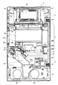
また、図3は、メインパネルユニット4の主要部を示す前面扉2の背面拡大図である。なお、図3では、メインパネルユニット4の背面側にカバー部材200、300を取り付ける前の状態を示している。
Embodiments of the present invention will be described below with reference to the drawings.
FIG. 1 is an external front view showing an example of a slot machine according to the present invention. FIG. 2 is a rear view of the
FIG. 3 is an enlarged rear view of the
スロットマシン1は、前面が開放した箱形の筐体の内部に、変動表示手段としてのリール装置8や、メダル払出装置(メダルホッパー)等の各種機器が設けられるとともに、この筐体の前面に前面扉2が片開き形式に開閉可能に設けられることで概略構成されている。
The
前面扉2は、略矩形状に形成されたメインフレーム21に、上部ユニット3、メインパネルユニット4、下部パネルユニット5、下皿ユニット6、及び各種操作スイッチ等が配設されて構成される。
メインフレーム21は、上側略1/3の領域にメインパネルユニット4を配設するための開口部が設けられ、一方の長辺には前面扉2を筐体に取り付けるための取付プレート23が固着されている。取付プレート23の上下2箇所には、前面扉2を筐体に対して開閉可能とするためのヒンジ24、24が設けられている。
The
The
メインフレーム21の上方には、上部ユニット3が配設されている。上部ユニット3は、所定のベース部材に可動演出部材や発光装飾装置からなる演出ユニット32やスピーカ31等を配置されて構成される。上部ユニット3の底面の一部がメインフレーム21の上辺部(開口部の上方)に係合され、所定の固定部材(例えば、パネル固定部材)によって固着されることにより、上部ユニット3はメインフレーム21に取り付けられる。
スロットマシン1では、この上部ユニット3内の可動演出部材を動作させて所定の演出を行うことにより、例えば、特別入賞に内部当選したことを報知する。
The
In the
メインフレーム21に形成された開口部には、メインパネルユニット4が配設される。メインパネルユニット4は、メインパネルベース49の前面側にメインパネル41を備えて構成され、このメインパネル41の略中央には後方を視認可能な(例えば透明の)図柄表示窓部42が形成されている。この図柄表示窓部42を透して、筐体内に配設されたリール8装置を視認可能となっている。
The
リール装置8は、複数の(例えば3つ)円筒形のリール8a、8b、8c、すなわち、第1リール(左リール)8a、第2リール(中リール)8b、及び、第3リール(右リール)8cが水平方向に並設されて構成されている。これらのリール8a、8b、8cの外周面には、所定の配列に従って複数の図柄が配置されている。複数の図柄としては、ボーナス入賞に対応する特別入賞図柄(例えば、7、BAR)と、特別入賞図柄以外の図柄(例えば、リプレイ、ベル、スイカ、チェリー、ブランク等)がある。
The reel device 8 includes a plurality of (for example, three)
各リール8a、8b、8cにはそれぞれ、リール用モータ(ステッピングモータ、図示略)が設けられており、各リール8a、8b、8cを独立して回転駆動ならびに回転停止することが可能となっている。
リール用モータによりリール8a、8b、8cを回転させることにより、図柄表示窓部42から視認される複数種類の図柄を、例えば上から下へと循環するように変動させる(変動表示)。一方、リール8a、8b、8cが停止している状態では、各リール8a、8b、8cについて、連続する所定数(例えば、3つ)の図柄が図柄表示窓部42を介して視認可能となっており、つまり図柄表示窓部42には3×3の計9つの図柄が停止表示されることとなる。
Each
By rotating the
図柄表示窓部42から視認される3×3の図柄行列に対しては、複数の有効化可能ラインが設定されている。すなわち、例えば、各リール8a、8b、8c中段の図柄を横切る有効化可能ライン(中段横ライン)、各リール8a、8b、8c上段の図柄を横切る有効化可能ライン(上段横ライン)、各リール8a、8b、8c下段の図柄を横切る有効化可能ライン(下段横ライン)、第1リール8a下段−第2リール8b中段−第3リール8c上段にかけて各リール8a、8b、8cを斜めに横切る有効化可能ライン(右上がりの斜めライン)、及び、第1リール8a上段−第2リール8b中段−第3リール8c下段にかけて各リール8a、8b、8cを斜めに横切る有効化可能ライン(右下がりの斜めライン)の5ラインが、有効化可能ラインとして設定されている。
A plurality of enableable lines are set for the 3 × 3 symbol matrix visually recognized from the
そして、遊技者によるメダルの投入又はクレジットからの入力(以下、賭入力と称する)によって設定されたベット数(賭数)に応じて所定の有効化可能ラインが有効化され、この有効ライン上に形成された図柄組合せ態様に基づいて入賞の成立/不成立が判断される。例えば、ベット数1では中段横ラインが有効ラインとなり、ベット数2では中段横ラインに加え、上下段横ラインが有効ラインとなり、ベット数3では上中下段横ラインに加え、右上がり、右下がりの斜めラインが有効ラインとなる。
なお、ベット数が3の場合でのみゲームを実行可能な所謂3枚がけ専用としてもよく、この場合は常に5つの有効化可能ラインが有効ラインとなる。また、ベット数には無関係にすべてのラインを有効としてもよい。
A predetermined enabling line is activated according to the number of bets (the number of bets) set by the player's insertion of medals or input from credits (hereinafter referred to as betting input). Whether or not a winning is achieved is determined based on the formed symbol combination mode. For example, in the case of 1 bet, the middle horizontal line becomes an effective line, in the case of 2 bets, the upper and lower horizontal lines become effective lines in addition to the middle horizontal line, and in the case of 3 bets, the upper, middle and lower horizontal lines are added to the right. The diagonal line is the effective line.
It should be noted that it is possible to dedicate so-called three cards that can be executed only when the number of bets is three. In this case, five valid lines are always valid lines. Alternatively, all lines may be valid regardless of the number of bets.
メインパネルユニット4において、図柄表示窓部42の上方には、所定の装飾の他、入賞役構成や入賞役に対応する配当等が表示された配当表示パネル43が配設されている。
図柄表示窓部42の下方には、クレジット数表示部44、払出数表示部45、獲得枚数表示部46が設けられている。クレジット数表示部44は、クレジットとして記憶されているメダル数を表示し、払出数表示部45は、ボーナスゲーム時の払出枚数を表示するものである。また、獲得枚数表示部46は入賞成立時の獲得枚数を表示するものである。これらの表示部44、45、46は、後方を透視可能な透明部材の奥に、例えば、7セグメントのLEDからなる表示部を備えて構成され、その点灯状態によって各種情報を表示する。
In the
Below the symbol
クレジット数表示部44の左方には、各種遊技状態を表示する遊技状態表示部47が設けられており、その奥に配されたランプの点灯状態により現在の遊技状態を表示する。遊技状態表示部47は、例えば、ベット操作が行われスタートレバー73によるゲームのスタート操作が有効であることを示すスタート表示部、遊技者がスタートレバー73を操作してからリールが回転するまでに待ち時間がある(前回のゲーム開始から一定時間経過していないためにリールの回転開始を待機している状態)ことを示すウェイト表示部、再遊技入賞(リプレイ入賞)が成立してリプレイゲームが付与されたことを示すリプレイ表示部、スロットマシン1が遊技可能な待機状態であることを示しベット操作を示唆するインサートメダル表示部、で構成される。
On the left side of the credit
獲得枚数表示部46の右方には、ベット操作によって設定されたベット数(最高3枚)を表示するベット数表示部48が設けられている。このベット数表示部48は、その奥に配されたランプの点灯状態によりメダルのベット数を表示する。
On the right side of the acquired
また、メインパネルユニット4において、メインパネルベース49の背面側には、周辺部に起立壁491が形成されており、この起立壁491には、後述する各種操作部からの配線を挿通させる開口部492、493、494が下方に向けて形成されている。そして、この起立壁491で囲まれた凹部には、各種操作部からの出力信号を集約して遊技制御装置(図示略)に出力する中継基板(ディジタル表示基板)100が配設されている。
中継基板100の前面側には、クレジット数表示部44、払出表示部45、獲得枚数表示部46等の表示部(例えば、LED)が設けられている。一方、図3に示すように、中継基板100の背面側には、各種操作部からの出力信号を入力する入力端子(基板コネクタ)101、102、103、及び遊技制御装置と接続するための入出力端子(基板コネクタ)104が設けられている。
例えば、入力端子101には、マックスベットボタン71、スタートレバー75、及びクレジット選択ボタン73からの配線コネクタ(図示略)が、メインパネルベース49の開口部492を通して接続される。入力端子102には、セレクタユニット91、リールストップボタン74a、74b、74c等からの配線コネクタ(図示略)が、メインパネルベース49の開口部493を通して接続される。入力端子103には、前面扉の開放検出センサ95からの配線コネクタ(図示略)がメインパネルベース49の開口部494を通して接続される。そして、入力端子101、102、103に入力された信号は中継基板100で集約され、入出力端子104にコネクタ接続された遊技制御装置に出力される。つまり、各種操作部からの出力信号は、入力端子101、102、103、及び入出力端子104からなる配線接続部を介して前記遊技制御手段に出力される。
Further, in the
Display units (for example, LEDs) such as a credit
For example, a wiring connector (not shown) from the
また、中継基板100には、スロットマシン1の機械割を段階的に変更(いわゆる設定変更)するための設定操作スイッチ105が設けられている。
中継基板100の背面側は、第2カバー部材300で覆われる。すなわち、メインパネルベース49の起立壁491と第2カバー部材300により、中継基板100が収納された凹部が閉塞されることとなる。第2カバー部材300の取付構成については後述する。
In addition, the
The back side of the
なお、入出力端子104は、遊技制御装置からの制御信号が入力可能に構成され、この制御信号に基づいて表示部の発光制御等が行われることとなる。つまり、入出力端子104は、遊技制御装置と双方向通信が可能に構成されている。
The input /
メインフレーム21の開口部の下方(メインパネルユニット4と下部パネルユニット5に挟まれる部分)には、前方側に突出する段部22が形成されている。
段部の上面22aには、メダル投入口72、マックスベットボタン71が設けられている。
メダル投入口72は、段部上面22aの正面視右側(前面扉2の開放端側)に配設されている。遊技者がこのメダル投入口72にメダルを投入してベット操作を行うことにより、ゲームが実行可能となる。このメダル投入口72から投入されたメダルが通過する経路には、メダルの通過を検知するメダル検出センサを備えたセレクタユニット91が設けられており、このセレクタユニット91による検出情報をもとにメダルの投入枚数がカウントされる。
Below the opening of the main frame 21 (a portion sandwiched between the
A
The
マックスベットボタン71は、段部上面22aの正面視左側に配設されている。マックスベットボタン71は、押圧操作を一度行うことでクレジットからベット数の限度数(例えば、3枚)まで入力できる。
The
段部正面22bには、クレジット選択ボタン(精算ボタン)73、リールストップボタン74、スタートレバー75、メダル詰まり解消ボタン76、及び鍵穴77が設けられている。
クレジット選択ボタン73は、メダル投入口72から投入されたメダル又は入賞が成立することにより払い出されるメダルをクレジットとして記憶可能なクレジット状態と、記憶不能な非クレジット状態を切り換えるためのものである。例えば、クレジット状態において、メダル投入口72から最大ベット数(例えば、3枚)を超えるメダルが投入された場合は、最大ベット数を超えた分のメダルは、所定数(例えば50枚)までクレジットとしてスロットマシン1に記憶され、以降のゲームで使用できる。また、クレジットとして記憶可能な所定数を超えるメダルが投入された場合は、受け皿62に返却される。一方、非クレジット状態では、最大ベット数を超えた分のメダルは受け皿62に返却される。
A credit selection button (payment button) 73, a reel stop button 74, a
The
リールストップボタン74は、第1リール8a、第2リール8b、及び第3リール8cとそれぞれ1対1で対応付けられて設けられた第1リールストップボタン74a、第2リールストップボタン74b、及び第3リールストップボタン74cで構成され、停止操作に応じて対応するリール8a、8b、8cの回転をそれぞれ停止させるためのものである。これらのリールストップボタン74a、74b、74cは、例えば、有色半透明の樹脂部材などで形成されている。また、リールストップボタン74a、74b、74cの奥には、該リールストップボタン74a、74b、74cの操作により各リールを停止可能な状態であることを、点灯により報知するためのストップボタンLED(図示略)がそれぞれ設けられている。
The reel stop button 74 includes a first
スタートレバー75は、一区切りのゲームを開始させるための操作レバーである。メダル詰まり解消ボタン76は、メダル投入口72内でメダル詰まりが発生した場合にこれを解消するためのものである。鍵穴77は、前面扉2を開く際、又はスロットマシン1のエラー(例えば、ホッパーエラー)状態をリセットする際に鍵を差し込むためのものである。
The
上述したように、メインフレーム21の段部22には、マックスベットボタン71、スタートレバー71、リールストップボタン74等の操作手段が、操作部位を外部に露呈された状態で配設されている。これらの操作手段からの出力信号はメインパネルユニット4を構成する中継基板100に集約され、中継基板100の入出力端子104から遊技制御装置(図示略)に出力されるようになっている。
As described above, the
メインフレーム21の段部22の下方には、前面扉2の下部領域を構成する下側パネルユニット5が配設される。下側パネルユニット5は、所定のベース(枠体)に装飾パネルがはめ込まれて構成されており、装飾パネルには、例えば、スロットマシンの機種名や入賞役等が表示される。
メインフレーム21の最下部(下側パネルユニット5の下方)には、下皿ユニット6が配設される。下皿ユニット6は、灰皿61、メダルを貯留するための受け皿62、スピーカの前面を覆うスピーカカバー63、メダル払出口64等を備える。スピーカカバー63の後方には、スピーカ93が配設される。
A
A
メインフレーム21の背面側には、メダル投入口72から投入されたメダルを検知するメダル検出センサを備えたセレクタユニット91、投入されたメダルを流下させるメダル流路92、スピーカ93、遊技制御装置(図示略)からの制御信号を中継する下部中継基板ユニット94等が配設される。
また、マックスベットボタン71とスタートレバー75の背面側は第1カバー部材200によって覆われており、さらに、第1カバー部材200と中継基板100(入力端子101、102、103、及び入出力端子104を含む)の背面は第2カバー部材300で覆われている。第1カバー部材200及び第2カバー部材300の取付構成については後述する。
On the back side of the
Further, the back side of the
上述したように、本実施形態のスロットマシン1は、前面が開放した箱形の筐体(図示略)と、この筐体前面に開閉可能に軸着された前面扉2と、複数の図柄を外周面に表示された複数のリール8a、8b、8cを備え、リール8a、8b、8cを回転させることにより可変表示ゲームを行うリール装置(変動表示手段)8と、リール装置8による可変表示ゲームを実行するためのマックスベットボタン(賭入力操作手段)71、及びセレクタユニット(賭入力手段)91と、マックスベットボタン71又はセレクタユニット91による賭入力の後、可変表示ゲームを開始するためのスタートレバー(スタート操作手段)75と、マックスベットボタン71又はセレクタユニット91からの出力信号、及びスタートレバー75からの出力信号に基づいて、可変表示ゲームに関する制御を行う遊技制御装置(遊技制御手段)と、マックスベットボタン71、セレクタユニット91、及びスタートレバー75からの出力信号を集約して遊技制御装置に出力する中継基板100と、を備える。
As described above, the
スロットマシン1においてゲームを行う場合、まず、メダル投入口72からメダルを投入するか、或いはマックスベットボタン71を操作してクレジットから賭数を入力する(賭入力)。賭入力がなされると、ベット数に応じて有効ラインが設定され、スタートレバー75の操作が有効な状態、すなわちゲームを開始可能な状態となる。そして、スタートレバー75を操作すると、遊技制御装置(図示略)において内部抽選処理がなされて入賞の当選/非当選が決定されるとともに、リール装置8の変動が開始される。
所定時間経過後、リールストップボタン74a、74b、74cの操作に基づいて、リール8a、8b、8cの回転が停止されることで、図柄表示窓部42に所定の図柄が停止表示される。このとき、内部抽選結果が特定結果となった場合(例えば、特別入賞(ボーナス入賞)や小役入賞に内部当選した場合)に、特定の図柄組合せ態様(内部当選した入賞に対応する図柄組合せ態様)を形成し得るように複数のリールの停止制御が行われる。そして、内部当選した入賞に対応する図柄組合せ態様が有効ライン上に形成された場合に入賞が成立し、当該入賞に対応する遊技価値が付与される(例えば、入賞メダルが払い出される)。以上で一区切りのゲームが終了し、以降、この操作を繰り返すことによってゲームを進行させるようになっている。
つまり、スロットマシン1は、例えば、マックスベットボタン71による賭入力を条件に、その後のスタートレバー75の操作に基づいて可変表示ゲームを実行し、可変表示ゲームの結果に関連して遊技者に所定の遊技価値を付与する。
When a game is played in the
After the predetermined time has elapsed, the rotation of the
That is, for example, the
また、本実施形態のスロットマシン1において、前面扉2には、マックスベットボタン71及びスタートレバー75の裏面側を覆う第1カバー部材200と、第1カバー部材200及び中継基板100を覆う第2カバー部材300と、が設けられている。
なお、第1カバー部材200及び第2カバー部材300は、前面扉2に直接取り付ける構成としても良いし、メインパネルユニット4のメインパネルベース49等を介して前面扉2に取り付ける構成としても良い。本実施形態では、第1カバー部材200は前面扉2に直接取り付けられ、第2カバー部材300はメインパネルベース49に取り付けられる。
In the
The
以下に、第1カバー部材100及び第2カバー部材300の取付構成について説明する。
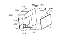
図4は第1カバー部材200を前方から見た斜視図であり、図5は第1カバー部材200を後方から見た斜視図である。
Below, the attachment structure of the
4 is a perspective view of the
図4、5に示すように、第1カバー部材200は、底面202に側壁201、203、及び背面壁204が形成された、前方及び上方に開口部された箱状部材であり、例えば、透明な樹脂材料によって一体的に成形されている。
As shown in FIGS. 4 and 5, the
第1カバー部材200の底面202には、断面鉤型の仕切り壁205が形成され、この仕切り壁205と側壁201の上方は上部壁体206で連結されている。上部壁体206は、所定の厚さを有するとともに、その上面は前方下側に向けて傾斜されている(傾斜部206a)。上部壁体206の上面と第2カバー部材300とを外接させるために、上部壁体206が所定の厚さを有する、言い換えれば、背面壁204及び側壁201が所定の高さを有するようにしている。なお、上部壁体206の内部は中空状に形成されてもよい。
A
底面202、側壁203、仕切り壁205、及び背面壁204で囲まれた正面視右側の空間は、マックスベットボタン71の後方側でありコネクタが設けられる部位(図3参照)を収納する第1収納部210となる。なお、マックスベットボタン71の下部が、第1収納部210の上方の開口から臨んで配置されることとなる。第1収納部210を構成する背面壁204の上部は、メインパネルベース49の形状に合わせて凹状切欠部204aと円弧状切欠部204bが形成されている。
A space on the right side in front view surrounded by the
底面202、側壁201、仕切り壁205、及び上部壁体206で囲まれた正面視左側の空間は、スタートレバー75の後方側でありコネクタが設けられる部位(図3参照)を収納する第2収納部220となる。底面202の第2収納部220を構成する部分には、スタートレバー75の背面部のうち収容しきれない部位を外部に臨ませる切欠部202aが形成されている。
また、底面202の側壁201側の縁部(切欠部202aの縁部)から内側(上方)に向けてスタートレバー75をネジ留めするための取付部207aが形成されている。上部壁体206の下面であって、取付部207aに対向する位置には、内側(下方)に向けてスタートレバー75をネジ留めするための取付部207bが形成されている。
また、第2収納部220には、スタートレバー75をネジ留めするときの取付作業を行うために、後方に向けて開口部204aが形成されている。
The space on the left side of the front view surrounded by the
Further, a mounting
In addition, an
図6は、メインパネルユニット4の主要部を示す前面扉2の背面拡大図である。なお、図6では、メインパネルユニット4の背面側に第1カバー部材200だけを取り付けた状態を示している。
図6に示すように、第1カバー部材200は、マックスベットボタン71の下部が第1収納部210の上方の開口に臨むとともに、スタートレバー75の背面部が第2収納部220の切欠部202aに当接して収納されるように配設される。このとき、第1カバー部材200の背面壁204に形成された凹状切欠部204aにはメインパネルベース49の開口部492を形成する起立壁491の突出部が位置し、円弧状切欠部204bにはメインパネルベース49のカシメ部材取付部495が位置することとなる。また、第1カバー部材200の下面は、前面扉2の段部22の背面側に形成された後方に突出した突出部25の上面に当接され、第1カバー部材の取り外しを不能としている。
FIG. 6 is an enlarged rear view of the
As shown in FIG. 6, in the
そして、第2収納部220の後方開口部204aから取付部207a、207bを介して、スタートレバー75の取付部75a、75aにネジを挿通し、前面扉2のメインフレーム21にネジ留めすることにより、スタートレバー75と第1カバー部材200は一体的に前面扉2に取り付けられる。すなわち、第1カバー部材200によってマックスベットボタン71及びスタートレバー75の裏面側が覆われる。
Then, screws are inserted into the mounting
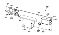
図7は第2カバー部材300の背面図であり、図8は第2カバー部材300を後方から見た斜視図である。
図7、8に示すように、第2カバー部材300は、略矩形状の第1平面部301と、第1平面部301の背面視左上部から延設された略矩形状の第2平面部302と、を有する板状部材であり、例えば、透明な樹脂材料によって一体的に成形されている。
FIG. 7 is a rear view of the
As shown in FIGS. 7 and 8, the
第1平面部301の左半部(第2カバー部材300の略中央)には、中継基板100に接続される配線端部のコネクタ(配線コネクタ)を収容するために、後方に向けてT字状の凹部304が形成されている。このT字状凹部304には、中継基板100の入出力端子104及び入力端子102が収納される。また、T字状凹部304の下方は開口されており、遊技制御装置からの配線コネクタがこの開口部304aを介して入出力端子104に接続されることとなる。なお、開口部304aの大きさは、遊技制御装置からの配線コネクタの大きさ(入出力端子104の大きさ)よりも小さいので、第2カバー部材300を取り外さない限り配線コネクタを抜いて外部へ引き抜くことは不可能となっている。
In the left half of the first flat surface portion 301 (substantially the center of the second cover member 300), a T-shape is formed rearward to accommodate a connector (wiring connector) at the wiring end connected to the
第1平面部301の右上部には、後方に向けて略矩形状の凹部303が形成されている。矩形状凹部303には、中継基板100の入力端子101に接続される配線コネクタが収納される。第1平面部301のT字状凹部の右側(押圧部301a)には、カシメ部材400を取り付けるための取付部307が形成されている。
A substantially
第2平面部302には、中継基板100の設定操作スイッチ105を操作するための開閉窓部305が形成されている。開閉窓部305を覆うように、開閉窓部305を開状態又は閉状態に変換する開閉部材(スライドカバー)310が取り付けられる(図2参照)。また、開閉窓部305の右側には、開閉部材310に形成されている係止片(図示略)によって前面側に押圧された場合に背面側に向けて付勢する板バネ306が、上下に切り込み加工を施すことにより一体的に形成されている。開閉部材310は、係止片が開口窓部305の端部に係止されることによって閉状態に固定されるとともに、右側にスライドされると板バネ306の付勢力によって容易に開状態とされる。
第2平面部302の左下部には、後方に向けて略矩形状の凹部305が形成されている。矩形状凹部305には、中継基板100の入力端子103に接続される配線コネクタが収納される。
An opening /
A substantially rectangular
第1平面部301の右側辺(凹部303の側壁)には第1平面部301より前方に突出した突出部309が形成されており、この突出部309には第2カバー部材300をメインパネルベース49に取り付けるためのフック部309aが形成されている。また、第2平面部の左側辺には第2平面部302より前方に突出した突出部308が形成されており、この突出部308には第2カバー部材300をメインパネルベース49に取り付けるための係合片308aが形成されている。
また、第2カバー部材300の第1平面部301及び第2平面部302には、第2カバー部材300をメインパネルベース49に隙間なく取り付け、中継基板100の収納空間を閉塞するために、中継基板100の外形に沿った微小高さの起立壁(図示略)が形成されている。第2カバー部材の押圧部301aは、この起立壁よりも外側に延在する。
第2カバー部材300の起立壁が、中継基板100の外形に沿って形成されているメインパネルベース49の起立壁491に嵌合されることで、中継基板100の入力端子101、102、103、及び入出力端子104は、T字状凹部304の下側開口304a及びメインパネルベース49の開口部492、493、494を除いて外部空間と遮断されることとなる。
A protruding
In addition, the
The rising wall of the
図6に示すように、第1カバー部材200が前面扉2(メインフレーム21)に取り付けられた後、その後方から第2カバー部材300が取り付けられる。このとき、第1カバー部材200の背面壁204の位置は、メインパネルベース49の収納凹部を形成する起立壁491と同等若しくは後方側となる。具体的には、メインパネルベース49の係合孔(図示略)に係合片308aを係合させ第2カバー部材300の左側を固定した後、メインパネルベース49の係止部(図示略)にフック部309aを係止させ右側を固定することで、第2カバー部材300を取り付ける。
As shown in FIG. 6, after the
このとき、第2カバー部材300の押圧部301aによって第1カバー部材200の背面の一部が押さえつけられる。なお、第2カバー部材200の押圧部301aによって第1カバー部材200の背面の全部が押さえつけられるようにしてもよい。
また、第2カバー部材300の突出部309の下辺が第1カバー部材200の上部壁体206の上面と外接することとなる。すなわち、第2カバー部材300は、第1カバー部材に外接して前面扉2に取り付けられる。
At this time, a part of the back surface of the
In addition, the lower side of the
さらに、第2カバー部材300は、取付部307にカシメ部材400を挿通してメインパネルベース49のカシメ部材取付部495に固着することで、メインパネルベース49に着脱不能に取り付けられる。ここで、カシメ部材400は、外部からカシメ部材取付部495内の係止状態を解除できないように取り付ける部材で、破壊しない限り取付状態を解除できない止着部材である。なお、メインパネルユニット4は前面扉2に着脱不能に取り付けられるので、第2カバー部材300は前面扉2に対して着脱不能に取り付けられることになる。ただし、中継基板100を修理する等、第2カバー部材300を取り外す必要が生じた場合には、カシメ部材400を破壊することにより取り外すことは可能である。
このようにして、第1カバー部材200及び第2カバー部材300は、前面扉2の背面側に取り付けられる(図2参照)。
Further, the
Thus, the
上述したように、本実施形態のスロットマシン1において、前面扉2には、マックスベットボタン71及びスタートレバー75の裏面側を覆う第1カバー部材200と、第1カバー部材200及び中継基板100を覆う第2カバー部材300と、が設けられ、第2カバー部材300はカシメ部材400を用いて前面扉2に着脱不能に取り付けられている。
これにより、第2カバー部材300を取り外さない限り、マックスベットボタン71及びスタートレバー75からの配線コネクタを接続する中継基板上の入力端子(基板コネクタ)101は外部に露呈されないので、この入力端子101に打ち込み機の配線コネクタが接続されるのを防止できる。
As described above, in the
Thus, unless the
また、第2カバー部材200を取り外さない限り、遊技制御装置からの配線コネクタを、中継基板上の入出力端子104から取り外すことが困難となるので、遊技制御装置からの配線コネクタに打ち込み機のコネクタが接続されるのを防止できる。
さらに、第1カバー部材200を取り外さない限り、中継基板100からの配線コネクタをマックスベットボタン71側のコネクタ又はスタートレバー75側のコネクタから取り外すことが困難となるので、この中継基板100からの配線コネクタに打ち込み機のコネクタが接続されるのを防止できる。つまり、打ち込み機によるクレジットからの賭入力やスタート操作が不可能となる。
したがって、コネクタ接続により打ち込み機をスロットマシン1に簡単に取り付けることはできないので、打ち込み祈祷の不正機器の使用を防止することができる。
Further, unless the
Further, unless the
Therefore, since the driving machine cannot be easily attached to the
また、第2カバー部材300は、第1カバー部材300に外接するように前面扉2に取り付けられるので、第1カバー部材300に覆われたマックスベットボタン71及びスタートレバー75の背面側は外部空間と遮断されることとなる(ただし、スタートレバー75の背面側は開口部を介して外部に露呈される)。これにより、マックスベットボタン71及びスタートレバー75から中継基板100への配線を改変することも困難となるので、より厳重に不正機器の使用を防止することができる。
Further, since the
さらに、第2カバー部材300は、開閉部材310によって開状態又は閉状態に変換される開閉窓部305を有し、開閉窓部305に設定操作スイッチ105が位置するように配設されるので、開閉部材310により開閉窓部305を閉鎖することが可能となり、営業中等に針金等の不正部材を前面扉2の隙間等から挿入して設定スイッチ105を不正に操作することを防止できる。また、第2カバー部材300の開閉窓部305を開状態に変換すれば、設定操作スイッチ105を操作することができるので、第2カバー部材300を設けることにより設定操作スイッチ105の操作が妨げられることもない。
Further, the
以上、本発明者によってなされた発明を実施形態に基づいて具体的に説明したが、本発明は上記実施形態に限定されるものではなく、その要旨を逸脱しない範囲で変更可能である。 As mentioned above, although the invention made by this inventor was concretely demonstrated based on embodiment, this invention is not limited to the said embodiment, It can change in the range which does not deviate from the summary.
また、今回開示された実施の形態はすべての点で例示であって制限的なものではないと考えられるべきである。本発明の範囲は上記した説明ではなくて特許請求の範囲によって示され、特許請求の範囲と均等の意味および範囲内でのすべての変更が含まれることが意図される。 In addition, it should be considered that the embodiment disclosed this time is illustrative and not restrictive in all respects. The scope of the present invention is defined by the terms of the claims, rather than the description above, and is intended to include any modifications within the scope and meaning equivalent to the terms of the claims.
1 スロットマシン
2 前面扉
3 上部ユニット
4 メインパネルユニット
5 下部パネルユニット
6 下皿ユニット
8 リール装置(変動表示手段)
21 メインフレーム
71 マックスベットボタン(賭入力操作手段)
75 スタートレバー(スタート操作手段)
91 セレクタユニット(賭入力手段)
100 中継基板
101、102、103 入力端子(配線接続部)
104 入出力端子(配線接続部)
200 第1カバー部材
210 第1収納部
220 第2収納部
207a、207b 貫通孔
300 第2カバー部材
305 開閉窓部
310 開閉部材
400 カシメ部材
1
21
75 Start lever (start operation means)
91 Selector unit (betting input means)
100
104 I / O terminal (wiring connection)
200
Claims (2)
この筐体前面に開閉可能に軸着された前面扉と、
複数の図柄を外周面に表示された複数のリールを備え、リールを回転させることにより可変表示ゲームを行う変動表示手段と、
前記変動表示手段による可変表示ゲームを実行するための賭入力手段と、
前記賭入力手段による賭入力の後、可変表示ゲームを開始するためのスタート操作手段と、
前記賭入力手段及び前記スタート操作手段からの出力信号に基づいて、可変表示ゲームに関する制御を行う遊技制御手段と、
前記賭入力手段及び前記スタート操作手段からの出力信号を集約し、配線接続部を介して前記出力信号を前記遊技制御手段に出力する中継基板と、を備え、
前記賭入力手段による賭入力を条件に、その後の前記スタート操作手段の操作に基づいて可変表示ゲームを実行し、該可変表示ゲームの結果に関連して遊技者に所定の遊技価値を付与するスロットマシンにおいて、
前記スタート操作手段は、前記前面扉の前面側に操作部が露呈されるとともに、裏面側で前記中継基板に接続されるように配設され、
前記賭入力手段は、クレジットから賭入力を行うための賭入力操作手段を含み、
前記前面扉には、
前記スタート操作手段の裏面側を覆う第1カバー部材と、
前記第1カバー部材及び前記中継基板を覆う第2カバー部材と、が設けられ、
前記第1カバー部材は、前記賭入力操作手段の裏面側を覆い、前記賭入力操作手段を収納する第1収納部と、前記スタート操作手段を収納する第2収納部を有し、
前記第2収納部には、前記スタート操作手段を前記前面扉に固着するためのネジを挿通する貫通孔が設けられるとともに、前記ネジの取付作業を行うための開口部が後方に向けて形成され、
前記スタート操作手段及び前記第1カバー部材は、当該第1カバー部材の後方開口部から前記貫通孔を介してネジ留めされることにより前記前面扉に取り付けられ、
前記第2カバー部材は、前記第1カバー部材に外接してカシメ部材を用いて前記前面扉に着脱不能に取り付けられることを特徴とするスロットマシン。 A box-shaped housing with an open front,
A front door pivotably attached to the front of the housing;
Fluctuation display means comprising a plurality of reels having a plurality of symbols displayed on the outer peripheral surface and performing a variable display game by rotating the reels;
Betting input means for executing a variable display game by the variable display means;
After the betting input by the betting input means, start operation means for starting a variable display game;
Game control means for controlling the variable display game based on output signals from the betting input means and the start operation means;
A relay board that aggregates output signals from the betting input means and the start operation means and outputs the output signals to the game control means via a wiring connection unit;
A slot for executing a variable display game based on a subsequent operation of the start operation means on the condition of a bet input by the bet input means and giving a predetermined game value to a player in relation to the result of the variable display game In the machine
The start operation means is arranged so that the operation unit is exposed on the front side of the front door and connected to the relay board on the back side,
The betting input means includes betting input operation means for inputting betting from credits,
In the front door,
A first cover member covering the back side of the start operation means;
A second cover member that covers the first cover member and the relay substrate;
The first cover member covers a back side of the betting input operation means, and has a first storage portion for storing the betting input operation means, and a second storage portion for storing the start operation means,
The second storage portion is provided with a through-hole through which a screw for fixing the start operation means to the front door is inserted, and an opening for performing the screw mounting operation is formed rearward. ,
The start operation means and the first cover member are attached to the front door by being screwed from the rear opening of the first cover member through the through hole,
The slot machine according to claim 1 , wherein the second cover member is attached to the front door in a non-detachable manner using a caulking member that circumscribes the first cover member .
前記第2カバー部材は、
開閉部材によって開状態又は閉状態に変換される開閉窓部を有し、
前記開閉窓部に前記設定操作スイッチが位置するように配設されることを特徴とする請求項1に記載のスロットマシン。 A setting operation switch for changing the machine discount step by step,
The second cover member is
Having an opening and closing window portion that is converted into an open state or a closed state by an opening and closing member;
The slot machine of claim 1, wherein the setting operation switch to the open window portion is disposed so as to be located.
Priority Applications (1)
| Application Number | Priority Date | Filing Date | Title |
|---|---|---|---|
| JP2007225231A JP5055552B2 (en) | 2007-08-31 | 2007-08-31 | Slot machine |
Applications Claiming Priority (1)
| Application Number | Priority Date | Filing Date | Title |
|---|---|---|---|
| JP2007225231A JP5055552B2 (en) | 2007-08-31 | 2007-08-31 | Slot machine |
Publications (2)
| Publication Number | Publication Date |
|---|---|
| JP2009056067A JP2009056067A (en) | 2009-03-19 |
| JP5055552B2 true JP5055552B2 (en) | 2012-10-24 |
Family
ID=40552377
Family Applications (1)
| Application Number | Title | Priority Date | Filing Date |
|---|---|---|---|
| JP2007225231A Expired - Fee Related JP5055552B2 (en) | 2007-08-31 | 2007-08-31 | Slot machine |
Country Status (1)
| Country | Link |
|---|---|
| JP (1) | JP5055552B2 (en) |
Family Cites Families (9)
| Publication number | Priority date | Publication date | Assignee | Title |
|---|---|---|---|---|
| JP3648566B2 (en) * | 1999-10-07 | 2005-05-18 | タイヨーエレック株式会社 | Bullet ball machine |
| JP4352541B2 (en) * | 1999-11-30 | 2009-10-28 | 株式会社三洋物産 | Game machine |
| JP2004187800A (en) * | 2002-09-20 | 2004-07-08 | Aruze Corp | Gaming machine |
| JP2004141319A (en) * | 2002-10-23 | 2004-05-20 | Sankyo Kk | Slot machine |
| JP2004242716A (en) * | 2003-02-10 | 2004-09-02 | Sankyo Kk | Slot machine using game ball |
| JP4304014B2 (en) * | 2003-07-03 | 2009-07-29 | サミー株式会社 | Control board protection structure for slot machines |
| JP2006051276A (en) * | 2004-08-16 | 2006-02-23 | Eimakkusu:Kk | Start lever lock device in slot machine |
| JP4923940B2 (en) * | 2006-10-18 | 2012-04-25 | 株式会社三洋物産 | Game machine |
| JP4897597B2 (en) * | 2007-07-13 | 2012-03-14 | サミー株式会社 | Game machine |
-
2007
- 2007-08-31 JP JP2007225231A patent/JP5055552B2/en not_active Expired - Fee Related
Also Published As
| Publication number | Publication date |
|---|---|
| JP2009056067A (en) | 2009-03-19 |
Similar Documents
| Publication | Publication Date | Title |
|---|---|---|
| JP2008307334A (en) | Game machine | |
| JP2009017966A (en) | Game machine, control method of game machine and storage medium | |
| JP5008231B2 (en) | Slot machine | |
| JP2004267357A (en) | Slot machine | |
| JP4861966B2 (en) | Slot machine | |
| JP2001204891A (en) | Slot machine | |
| JP2001170324A (en) | Game machine | |
| JP2001204883A (en) | Slot machine | |
| JP2008237512A (en) | Fraudulent operation preventing structure of game machine | |
| JP5627122B2 (en) | Slot machine | |
| JP2001112932A (en) | Pachinko game machine | |
| JP5055552B2 (en) | Slot machine | |
| JP2007143917A (en) | Control part structure of game machine | |
| JP2008000446A (en) | Game machine | |
| JP2007202696A (en) | Game machine | |
| JP5146987B2 (en) | Game machine | |
| JP6085285B2 (en) | Slot machine | |
| JP2005160907A (en) | Game machine | |
| JP4344711B2 (en) | Game machine | |
| JP2005168780A (en) | Game machine | |
| JP2009050526A (en) | Slot machine | |
| JP2008206708A (en) | Game machine | |
| JP6480301B2 (en) | Game machine | |
| JP4822400B2 (en) | Game machine | |
| JP4423395B2 (en) | Game machine |
Legal Events
| Date | Code | Title | Description |
|---|---|---|---|
| A621 | Written request for application examination |
Free format text: JAPANESE INTERMEDIATE CODE: A621 Effective date: 20081225 |
|
| A977 | Report on retrieval |
Free format text: JAPANESE INTERMEDIATE CODE: A971007 Effective date: 20110810 |
|
| A131 | Notification of reasons for refusal |
Free format text: JAPANESE INTERMEDIATE CODE: A131 Effective date: 20110823 |
|
| A521 | Request for written amendment filed |
Free format text: JAPANESE INTERMEDIATE CODE: A523 Effective date: 20111024 |
|
| RD02 | Notification of acceptance of power of attorney |
Free format text: JAPANESE INTERMEDIATE CODE: A7422 Effective date: 20111024 |
|
| TRDD | Decision of grant or rejection written | ||
| A01 | Written decision to grant a patent or to grant a registration (utility model) |
Free format text: JAPANESE INTERMEDIATE CODE: A01 Effective date: 20120605 |
|
| A01 | Written decision to grant a patent or to grant a registration (utility model) |
Free format text: JAPANESE INTERMEDIATE CODE: A01 |
|
| A61 | First payment of annual fees (during grant procedure) |
Free format text: JAPANESE INTERMEDIATE CODE: A61 Effective date: 20120705 |
|
| FPAY | Renewal fee payment (event date is renewal date of database) |
Free format text: PAYMENT UNTIL: 20150810 Year of fee payment: 3 |
|
| R150 | Certificate of patent or registration of utility model |
Ref document number: 5055552 Country of ref document: JP Free format text: JAPANESE INTERMEDIATE CODE: R150 |
|
| R250 | Receipt of annual fees |
Free format text: JAPANESE INTERMEDIATE CODE: R250 |
|
| R250 | Receipt of annual fees |
Free format text: JAPANESE INTERMEDIATE CODE: R250 |
|
| R250 | Receipt of annual fees |
Free format text: JAPANESE INTERMEDIATE CODE: R250 |
|
| R250 | Receipt of annual fees |
Free format text: JAPANESE INTERMEDIATE CODE: R250 |
|
| R250 | Receipt of annual fees |
Free format text: JAPANESE INTERMEDIATE CODE: R250 |
|
| R250 | Receipt of annual fees |
Free format text: JAPANESE INTERMEDIATE CODE: R250 |
|
| R250 | Receipt of annual fees |
Free format text: JAPANESE INTERMEDIATE CODE: R250 |
|
| LAPS | Cancellation because of no payment of annual fees |