JP5052988B2 - Steam cooker - Google Patents
Steam cooker Download PDFInfo
- Publication number
- JP5052988B2 JP5052988B2 JP2007206161A JP2007206161A JP5052988B2 JP 5052988 B2 JP5052988 B2 JP 5052988B2 JP 2007206161 A JP2007206161 A JP 2007206161A JP 2007206161 A JP2007206161 A JP 2007206161A JP 5052988 B2 JP5052988 B2 JP 5052988B2
- Authority
- JP
- Japan
- Prior art keywords
- steam
- cooking
- heated
- heater
- heating chamber
- Prior art date
- Legal status (The legal status is an assumption and is not a legal conclusion. Google has not performed a legal analysis and makes no representation as to the accuracy of the status listed.)
- Active
Links
Images


Description
本発明は、加熱室内に蒸気を噴出して被加熱物の調理を行う蒸気調理器に関する。 The present invention relates to a steam cooker that cooks an object to be heated by jetting steam into a heating chamber.
従来の蒸気調理器は特許文献1に開示されている。この蒸気調理器は過熱蒸気を加熱媒体とし、加熱室内に配された受皿上に被加熱物が載置される。加熱室の側方には水タンクが配され、水タンクから給水路を介して蒸気発生装置に給水される。蒸気発生装置は供給された水によって蒸気を生成して蒸気昇温装置に送出する。蒸気昇温装置は蒸気を更に加熱して過熱蒸気を生成し、過熱蒸気を加熱室に噴出して低酸素状態で被加熱物の調理が行われる。
A conventional steam cooker is disclosed in
これにより、被加熱物の酸化を防止し、脂質の酸化による臭いの発生や味の劣化を防止して良好な調理を行うことができる。また、被加熱物に含まれる油脂が溶解して蒸気の凝縮水とともに流下し、被加熱物を脱油して健康的な調理を行うことができる。 Thereby, oxidation of a to-be-heated material is prevented, generation | occurrence | production of the smell by oxidation of lipid, deterioration of a taste can be prevented, and favorable cooking can be performed. Moreover, the fats and oils contained in a to-be-heated material melt | dissolve and flow down with the condensed water of a vapor | steam, and a to-be-heated material can be deoiled and healthy cooking can be performed.
近年、消費者の健康に対する関心が高まり、脱油効果の高い調理器のニーズが高くなっている。上記従来の蒸気調理器によると、脱油効果を向上するためには調理温度を高くすることや調理時間を長くすることが必要であった。しかしながら、家庭用の蒸気調理器で使用できる電力が限られているため、調理温度を高くすることが困難である。一方、調理時間を長くすると使用者の利便性が悪くなる問題がある。また、調理温度を高くできないため調理時間の短縮が困難な問題もあった。 In recent years, consumer interest in health has increased, and the need for cookers with a high deoiling effect has increased. According to the conventional steam cooker, it has been necessary to increase the cooking temperature and lengthen the cooking time in order to improve the deoiling effect. However, it is difficult to increase the cooking temperature because electric power that can be used in a home-use steam cooker is limited. On the other hand, when the cooking time is lengthened, there is a problem that convenience for the user is deteriorated. There is also a problem that it is difficult to shorten the cooking time because the cooking temperature cannot be increased.
本発明は、利便性を低下させることなく容易に脱油効果を向上できる蒸気調理器を提供することを目的とする。また本発明は、調理時間を短縮できる蒸気調理器を提供することを目的とする。 An object of this invention is to provide the steam cooker which can improve the deoiling effect easily, without reducing the convenience. Moreover, an object of this invention is to provide the steam cooker which can shorten cooking time.
上記目的を達成するために本発明は、蒸気を発生する蒸気発生ヒータと、前記蒸気発生ヒータで発生した蒸気を昇温して過熱蒸気を生成するとともに加熱室内の蒸気を循環して加熱する蒸気加熱ヒータとを備え、前記加熱室内に供給された蒸気を用いて被加熱物を調理する蒸気調理器において、前記蒸気発生ヒータの供給電力を前記蒸気加熱ヒータの供給電力よりも大きくして被加熱物を調理する第1調理工程と、前記蒸気発生ヒータの供給電力を前記蒸気加熱ヒータの供給電力よりも小さくして被加熱物を調理する第2調理工程とを有し、被加熱物の内部温度が油脂溶融温度帯を超えて100℃以下の時に第1調理工程から第2調理工程に切り替えることを特徴としている。 In order to achieve the above object, the present invention provides a steam generating heater that generates steam, and steam that heats the steam generated by the steam generating heater to generate superheated steam and circulates and heats the steam in the heating chamber. A steam cooker for cooking an object to be heated using steam supplied into the heating chamber, wherein the power to be supplied to the steam generating heater is larger than the power to be supplied to the steam heating heater. A first cooking step for cooking an object, and a second cooking step for cooking the object to be heated by making the supply power of the steam generating heater smaller than the supply power of the steam heating heater, and the inside of the object to be heated It is characterized by switching from the first cooking process to the second cooking process when the temperature exceeds the oil melting temperature zone and is 100 ° C. or lower.
この構成によると、蒸気発生ヒータ及び蒸気加熱ヒータの駆動時には給水タンク等から蒸気発生ヒータに水が供給され、蒸気が発生する。発生した蒸気は蒸気加熱ヒータで更に昇温され、100℃よりも高温の過熱蒸気が生成される。過熱蒸気は加熱室に供給され、循環して蒸気加熱ヒータにより加熱される。これにより、高温の過熱蒸気による調理が行われる。 According to this configuration, when the steam generating heater and the steam heating heater are driven, water is supplied from the water supply tank or the like to the steam generating heater to generate steam. The generated steam is further heated by a steam heater, and superheated steam having a temperature higher than 100 ° C. is generated. The superheated steam is supplied to the heating chamber, circulates and is heated by the steam heater. Thereby, cooking by high temperature superheated steam is performed.
所定の調理メニューを開始すると蒸気発生ヒータの供給電力が蒸気加熱ヒータの供給電力よりも大きい第1調理工程が行われる。これにより、大量の過熱蒸気を加熱室に供給して調理が行われる。尚、蒸気加熱ヒータを停止した場合は大量の飽和蒸気を加熱室に供給して調理が行われる。被加熱物は大量の蒸気の潜熱によって内部温度が急激に上昇する。 When a predetermined cooking menu is started, a first cooking process is performed in which the supply power of the steam generating heater is larger than the supply power of the steam heating heater. Thereby, cooking is performed by supplying a large amount of superheated steam to the heating chamber. When the steam heater is stopped, cooking is performed by supplying a large amount of saturated steam to the heating chamber. The internal temperature of the object to be heated rises rapidly due to the latent heat of a large amount of steam.
被加熱物を蒸気により加熱すると内部温度が急激に上昇した後、100℃以下の範囲で内部温度の上昇が緩やかになる。その後、被加熱物の内部の水分が蒸発すると100℃を超えて更に内部温度が急激に上昇する。第1調理工程によって被加熱物の内部温度が100℃以下の範囲で約30〜60℃の油脂溶融温度帯を越えると油脂の滲み出しが始まり、第2調理工程に切り替えられる。 When the object to be heated is heated with steam, the internal temperature rapidly rises, and then the internal temperature rises gradually in the range of 100 ° C. or less. After that, when the moisture inside the object to be heated evaporates, the internal temperature rapidly rises above 100 ° C. When the internal temperature of the article to be heated exceeds about 30-60 ° C. in the first cooking step and the oil melting temperature range of about 30-60 ° C., the oil begins to ooze out and is switched to the second cooking step.
第2調理工程では蒸気発生ヒータの供給電力を蒸気加熱ヒータの供給電力よりも小さく設定される。これにより、循環により蒸気加熱ヒータで加熱された過熱蒸気または飽和蒸気によって被加熱物が調理される。その結果、被加熱物は主に表面が加熱され、所望の内部温度に維持されるとともに表面に焼き色が付けられて調理が完了する。 In the second cooking step, the supply power of the steam generating heater is set smaller than the supply power of the steam heating heater. As a result, the object to be heated is cooked by the superheated steam or saturated steam heated by the steam heater by circulation. As a result, the surface of the object to be heated is mainly heated and maintained at a desired internal temperature, and the surface is baked to complete cooking.
また本発明は上記構成の蒸気調理器において、被加熱物の種類に対応した調理メニューと、該調理メニューに応じた調理シーケンスデータとを記憶し、前記調理シーケンスデータは、被加熱物の種類に応じた油脂溶融温度特性に基づいて、第1調理工程から第2調理工程に切り替える時期のデータを保有することを特徴としている。 In the steam cooker having the above-described configuration, the present invention stores a cooking menu corresponding to the type of the object to be heated and cooking sequence data corresponding to the cooking menu, and the cooking sequence data corresponds to the type of the object to be heated. Based on the corresponding oil / fat melting temperature characteristics, it is characterized in that it retains data of the timing for switching from the first cooking step to the second cooking step.
この構成によると、調理メニューが選択されると選択した調理メニューに応じた調理シーケンスデータが呼び出される。調理シーケンスデータは被加熱物毎に異なる油脂溶融温度特性に基づいた第1、第2調理工程の切り替え時期のデータを保有する。第1調理工程が開始されると被加熱物毎に異なる切り替え時期が調理シーケンスデータから取得される。そして、第1調理工程の調理時間が取得した時期になると第2調理工程に切り替えられる。 According to this configuration, when a cooking menu is selected, cooking sequence data corresponding to the selected cooking menu is called up. The cooking sequence data holds data of the switching times of the first and second cooking steps based on the fat and oil melting temperature characteristics that are different for each article to be heated. When the first cooking step is started, a different switching time for each object to be heated is acquired from the cooking sequence data. And when it becomes the time which the cooking time of the 1st cooking process was acquired, it switches to the 2nd cooking process.
また本発明は上記構成の蒸気調理器において、被加熱物の量を入力する被加熱物量入力手段を備え、前記被加熱物量入力手段の入力情報に基づいて第1調理工程から第2調理工程に切り替える時期を可変したことを特徴としている。 In the steam cooker having the above-described configuration, the present invention further includes a heated object amount input means for inputting an amount of an object to be heated. From the first cooking process to the second cooking process based on input information of the heated object amount input means. It is characterized by changing the timing of switching.
この構成によると、調理メニューを選択して被加熱物量入力手段によって被加熱物の量が入力され、調理が開始される。第1調理工程が開始されると被加熱物毎に異なる切り替え時期が調理シーケンスデータから取得される。第1、第2調理工程の切り替え時期は被加熱物の量が多いと遅れるように可変され、被加熱物の量が少ないと早めるように可変される。そして、第1調理工程の調理時間が可変した時期になると第2調理工程に切り替えられる。 According to this configuration, the cooking menu is selected, the amount of the heated object is input by the heated object amount input means, and cooking is started. When the first cooking step is started, a different switching time for each object to be heated is acquired from the cooking sequence data. The switching timing of the first and second cooking steps is varied so as to be delayed when the amount of the object to be heated is large, and is varied so as to be advanced when the amount of the object to be heated is small. And it will be switched to a 2nd cooking process when the cooking time of a 1st cooking process becomes variable.
また本発明は上記構成の蒸気調理器において、被加熱物の内部温度が60〜80℃の時に第1調理工程から第2調理工程に切り替えたことを特徴としている。 Moreover, this invention is the steam cooker of the said structure, It switched to the 2nd cooking process from the 1st cooking process, when the internal temperature of a to-be-heated object is 60-80 degreeC.
また本発明は上記構成の蒸気調理器において、被加熱物の内部温度の温度変化率が略一定の状態から小さくなる時期に第1調理工程から第2調理工程に切り替えることを特徴としている。この構成によると、蒸気の供給によって被加熱物の内部温度が急激に上昇し、内部温度の上昇が緩やかになる時期に第1調理工程から第2調理工程に切り替えられる。 In the steam cooker having the above-described configuration, the present invention is characterized in that the first cooking step is switched to the second cooking step when the temperature change rate of the internal temperature of the object to be heated decreases from a substantially constant state. According to this configuration, the first cooking process is switched to the second cooking process at a time when the internal temperature of the object to be heated suddenly increases due to the supply of steam and the increase in the internal temperature becomes moderate.
また本発明は、蒸気を発生する蒸気発生ヒータと、前記蒸気発生ヒータで発生した蒸気を昇温して過熱蒸気を生成するとともに加熱室内の蒸気を循環して加熱する蒸気加熱ヒータとを備え、前記加熱室内に供給された蒸気を用いて被加熱物を調理する蒸気調理器において、前記蒸気発生ヒータの供給電力を前記蒸気加熱ヒータの供給電力よりも大きくして被加熱物を調理する第1調理工程と、前記蒸気発生ヒータの供給電力を前記蒸気加熱ヒータの供給電力よりも小さくして被加熱物を調理する第2調理工程とを有し、被加熱物の内部温度の温度変化率が略一定の状態から小さくなる時期に第1調理工程から第2調理工程に切り替えることを特徴としている。 The present invention also includes a steam generating heater that generates steam, and a steam heater that circulates and heats the steam in the heating chamber while heating the steam generated in the steam generating heater to generate superheated steam. In the steam cooker that cooks the object to be heated using the steam supplied into the heating chamber, the first power for cooking the object to be heated by making the supply power of the steam generating heater larger than the supply power of the steam heating heater. A cooking step and a second cooking step of cooking the object to be heated by making the supply power of the steam generating heater smaller than the supply power of the steam heating heater, and the temperature change rate of the internal temperature of the object to be heated is It is characterized by switching from the first cooking step to the second cooking step at a time when it becomes smaller from a substantially constant state.
この構成によると、所定の調理メニューを開始すると蒸気発生ヒータの供給電力が蒸気加熱ヒータの供給電力よりも大きい第1調理工程が行われる。これにより、大量の過熱蒸気を加熱室に供給して調理が行われる。尚、蒸気加熱ヒータを停止した場合は大量の飽和蒸気を加熱室に供給して調理が行われる。 According to this configuration, when a predetermined cooking menu is started, the first cooking process in which the supply power of the steam generating heater is larger than the supply power of the steam heating heater is performed. Thereby, cooking is performed by supplying a large amount of superheated steam to the heating chamber. When the steam heater is stopped, cooking is performed by supplying a large amount of saturated steam to the heating chamber.
蒸気の供給によって被加熱物の内部温度が急激に上昇し、内部温度の上昇が緩やかになる時期に第1調理工程から第2調理工程に切り替えられる。第2調理工程では蒸気発生ヒータの供給電力を蒸気加熱ヒータの供給電力よりも小さく設定される。これにより、循環により蒸気加熱ヒータで加熱された過熱蒸気または飽和蒸気によって被加熱物が調理される。 The supply of steam causes the internal temperature of the object to be heated to rapidly increase, and the first cooking process is switched to the second cooking process at a time when the increase in internal temperature becomes moderate. In the second cooking step, the supply power of the steam generating heater is set smaller than the supply power of the steam heating heater. As a result, the object to be heated is cooked by the superheated steam or saturated steam heated by the steam heater by circulation.
また本発明は上記構成の蒸気調理器において、第1調理工程で前記蒸気加熱ヒータを停止したことを特徴としている。 In the steam cooker having the above-mentioned configuration, the present invention is characterized in that the steam heater is stopped in the first cooking step.
また本発明は上記構成の蒸気調理器において、第2調理工程で前記蒸気発生ヒータを停止したことを特徴としている。 In the steam cooker having the above-described configuration, the steam generating heater is stopped in the second cooking step.
また本発明は上記構成の蒸気調理器において、前記蒸気加熱ヒータの輻射熱によって被加熱物を加熱することを特徴としている。この構成によると、蒸気加熱ヒータは例えば加熱室の天面に配され、蒸気加熱ヒータの輻射熱が被加熱物に照射されて加熱調理が行われる。 In the steam cooker having the above-described configuration, the present invention is characterized in that an object to be heated is heated by radiant heat of the steam heater. According to this configuration, the steam heater is disposed, for example, on the top surface of the heating chamber, and the object to be heated is irradiated with the radiant heat of the steam heater to perform cooking.
また本発明は上記構成の蒸気調理器において、前記蒸気発生ヒータの供給電力が第1調理工程よりも小さくて第2調理工程よりも大きく、前記蒸気加熱ヒータの供給電力が第1調理工程よりも大きくて第2調理工程よりも小さい中間調理工程を第1、第2調理工程の間に設けたことを特徴としている。 Moreover, this invention is a steam cooker of the said structure, The supply electric power of the said steam generation heater is smaller than a 1st cooking process, is larger than a 2nd cooking process, The supply electric power of the said steam heating heater is more than a 1st cooking process. An intermediate cooking process that is larger and smaller than the second cooking process is provided between the first and second cooking processes.
本発明によると、蒸気発生ヒータの供給電力を蒸気加熱ヒータの供給電力よりも大きい第1調理工程を有するので、大量の蒸気の潜熱によって肉類等の被加熱物の内部温度を急速に上昇させることができる。これにより、早期に被加熱物の内部温度を油脂溶融温度帯よりも高温にすることができる。 According to the present invention, since the first cooking step has a power supply of the steam generating heater larger than that of the steam heating heater, the internal temperature of the heated object such as meat can be rapidly increased by the latent heat of a large amount of steam. Can do. Thereby, the internal temperature of a to-be-heated material can be made higher than an oil-fat melting temperature zone at an early stage.
また、被加熱物の内部温度を油脂溶融温度帯を超えて油脂の滲み出しが始まった後に、蒸気発生ヒータの供給電力を蒸気加熱ヒータの供給電力よりも小さくした第2調理工程に切り替えるので、被加熱物を所望の内部温度に維持するとともに表面に焼き色を付けて調理を完了させることができる。 Moreover, since the internal temperature of the object to be heated exceeds the oil and fat melting temperature zone and the oil and fat starts to exude, the supply power of the steam generating heater is switched to the second cooking step, which is smaller than the supply power of the steam heating heater. The object to be heated can be maintained at a desired internal temperature, and the surface can be colored to complete cooking.
従って、被加熱物内部に適正な水分量を確保して美味しさを保持するとともに、調理時間を長くすることなく油脂溶融温度帯よりも高温の期間を長くすることができる。これにより、蒸気調理器の利便性を低下させずに被加熱物の脱油量を増加させて健康的な調理を行うことができる。また、被加熱物の内部温度が早期に高温になるため、調理時間を短縮することができる。被加熱物の脱油量を従来と同程度にすると、更に調理時間を短縮できる。 Accordingly, it is possible to secure an appropriate amount of water inside the heated object and maintain the taste, and to extend the period of time higher than the fat melting temperature zone without increasing the cooking time. Thereby, healthy cooking can be performed by increasing the deoiling amount of the object to be heated without reducing the convenience of the steam cooker. Moreover, since the internal temperature of a to-be-heated object becomes high temperature early, cooking time can be shortened. The cooking time can be further shortened if the oil removal amount of the object to be heated is set to the same level as before.
また本発明によると、被加熱物の内部温度の温度変化率が略一定の状態から小さくなる時期に第1調理工程から第2調理工程に切り替えるので、被加熱物の内部温度を100℃以下の適正な温度に維持することができる。従って、被加熱物の水分の減少を抑制して美味しさを維持した調理を簡単に実現することができる。 Further, according to the present invention, since the temperature change rate of the internal temperature of the object to be heated is switched from the first cooking process to the second cooking process at a time when the temperature change rate decreases from a substantially constant state, the internal temperature of the object to be heated is 100 ° C. or less. It can be maintained at an appropriate temperature. Therefore, the cooking which maintained the deliciousness by suppressing the reduction | decrease of the water | moisture content of a to-be-heated material can be implement | achieved easily.
また本発明によると、調理シーケンスデータが被加熱物の種類に応じた油脂溶融温度特性に基づいて、各被加熱物の第1調理工程から第2調理工程に切り替える時期のデータを保有するので、豚肉や牛肉等の被加熱物の種類に応じて最適な時期に第1、第2調理工程を切り替えることができる。従って、良好な調理を行うことができる。 Further, according to the present invention, the cooking sequence data is based on the oil / fat melting temperature characteristics according to the type of the object to be heated, and therefore holds the data of the timing for switching from the first cooking process to the second cooking process of each object to be heated. The first and second cooking steps can be switched at an optimal time according to the type of heated object such as pork or beef. Therefore, good cooking can be performed.
また本発明によると、被加熱物量入力手段の入力情報に基づいて第1調理工程から第2調理工程に切り替える時期を可変したので、被加熱物の量に応じて最適なタイミングで第1調理工程から第2調理工程に切り替えることができる。従って、より良好な調理を行うことができる。 Moreover, according to this invention, since the timing which switches from a 1st cooking process to a 2nd cooking process was changed based on the input information of to-be-heated material amount input means, the 1st cooking process was carried out at the optimal timing according to the amount of to-be-heated material. To the second cooking step. Therefore, better cooking can be performed.
また本発明によると、被加熱物の内部温度が60〜80℃の時に第1調理工程から第2調理工程に切り替えたので、被加熱物の水分の減少をより低減して美味しさを更に向上することができる。 According to the present invention, since the first cooking process is switched to the second cooking process when the internal temperature of the object to be heated is 60 to 80 ° C., the decrease in moisture of the object to be heated is further reduced to further improve the taste. can do.
また本発明によると、被加熱物の内部温度の温度変化率が略一定の状態から小さくなる時期に第1調理工程から第2調理工程に切り替えるので、被加熱物の内部温度を100℃以下の適正な温度に維持することができる。従って、被加熱物の水分の減少を抑制して美味しさを維持した調理を簡単に実現することができる。 Further, according to the present invention, since the temperature change rate of the internal temperature of the object to be heated is switched from the first cooking process to the second cooking process at a time when the temperature change rate decreases from a substantially constant state, the internal temperature of the object to be heated is 100 ° C. or less. It can be maintained at an appropriate temperature. Therefore, the cooking which maintained the deliciousness by suppressing the reduction | decrease of the water | moisture content of a to-be-heated material can be implement | achieved easily.
また本発明によると、第1調理工程で蒸気加熱ヒータを停止したので、大きな電力を蒸気発生ヒータに供給できる。これにより、被加熱物の内部温度を迅速に上昇させて脱油量を増加するとともに調理時間を短縮することができる。 According to the present invention, since the steam heater is stopped in the first cooking step, a large amount of electric power can be supplied to the steam generating heater. Thereby, while raising the internal temperature of a to-be-heated material rapidly, deoiling amount can be increased and cooking time can be shortened.
また本発明によると、第2調理工程で蒸気発生ヒータを停止したので、大きな電力を蒸気加熱ヒータに供給してより早期に調理を完了することができる。 According to the present invention, since the steam generating heater is stopped in the second cooking step, cooking can be completed earlier by supplying large electric power to the steam heating heater.
また本発明によると、蒸気加熱ヒータの輻射熱によって被加熱物を加熱するので、被加熱物に容易に焼き色を付けて調理時間をより短縮することができる。 In addition, according to the present invention, the object to be heated is heated by the radiant heat of the steam heater, so that the object to be heated can be easily colored and the cooking time can be further shortened.
また本発明によると、中間調理工程を第1、第2調理工程の間に設けたので、大型の被加熱物等に対してよりきめ細かい制御を行って良好な調理を行うことができる。 Moreover, according to this invention, since the intermediate cooking process was provided between the 1st and 2nd cooking process, finer control can be performed with respect to a large to-be-heated thing etc., and favorable cooking can be performed.
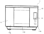
以下に本発明の実施形態を図面を参照して説明する。図1、図2は一実施形態の蒸気調理器を示す正面図及び側面図である。蒸気調理器1は過熱蒸気によって被加熱物を調理する。蒸気調理器1は直方体形状のキャビネット10を備えている。キャビネット10の正面には扉11が設けられる。
Embodiments of the present invention will be described below with reference to the drawings. 1 and 2 are a front view and a side view showing a steam cooker according to an embodiment. The
扉11は下端を中心に垂直面内で回動可能に枢支され、上部には扉11を開閉するためのハンドル12が設けられている。扉11の中央部11Cには耐熱ガラスをはめ込んで内部を視認できる透過部11a(図3参照)が設けられる。中央部11Cの左右には金属製装飾板を表面に設けた左側部11L及び右側部11Rが対称的に配置されている。扉11の右側部11Rには操作パネル13が設けられている。
The
図3は扉11を開いた状態の蒸気調理器1の正面図を示している。扉11はハンドル12を把持して手前に引くと回動し、垂直な閉鎖状態から水平な開放状態へと90゜姿勢を変えることができる。扉11を開くとキャビネット10の正面が露出する。
FIG. 3 shows a front view of the
扉11の中央部11Cに対応する箇所には加熱室20が設けられる。扉11の左側部11Lに対応する箇所には水タンク室70が設けられ、蒸気発生用の水を貯溜する水タンク71が収納される。扉11の右側部11Rに対応する箇所には特に開口部は設けられていないが、内部に制御基板(不図示)が配置されている。
A
加熱室20は略直方体に形成され、扉11に面した正面側の全面が被加熱物F(図5参照)を出し入れするための開口部20dになっている。扉11の回動により開口部20dが開閉される。加熱室20の壁面はステンレス鋼板で形成され、加熱室20の外周面には断熱対策が施されている。
The
図4は加熱室20内の詳細を示す正面図である。加熱室20の側壁には複数の受皿支持部20b、20cが異なる高さに設けられる。上段の受皿支持部20bは反射部68よりも下方に設けられる。受皿支持部20b、20cの一方または両方にはステンレス鋼板製の受皿21が係止される。受皿21上には被加熱物F(図5参照)を載置するステンレス鋼線製のラック22が設置される。
FIG. 4 is a front view showing details in the
過熱蒸気により調理を行う場合は、上段の受皿支持部20bに受皿21が設置される。これにより、後述するように反射部68の反射によって被加熱物Fの下面に過熱蒸気を導くことができる。上段及び下段の受皿支持部20b、20cに受皿21を設置してもよい。これにより、一度に多くの被加熱物Fを調理することができる。
When cooking with superheated steam, the
この時、受皿支持部20bに配される受皿21は通気性を有するように形成され、下段の受皿21上の被加熱部の上面に過熱蒸気が供給される。また、下段の受皿21上の被加熱部の下面は加熱室20の底面に配された加熱ヒータ101(図5参照)により加熱される。
At this time, the
加熱室20の奥側の背壁には左右方向の略中央部に吸気口28が設けられ、左方下部に排気口32aが設けられる。反射部68は加熱室20の両側壁に凹設され、表面が曲面により形成されている。後述する噴出カバー61から反射部68に向けて側方に噴き出された過熱蒸気は反射部68で反射して被加熱物Fの下方に導かれるようになっている。
The back wall on the back side of the
加熱室20の天面には、過熱蒸気を噴き出すステンレス鋼板から成る噴出カバー61が取り付けられる。噴出カバー61の右側部の手前側には加熱室20内を照明する照明装置69が設けられる。
An ejection cover 61 made of a stainless steel plate that ejects superheated steam is attached to the top surface of the
噴出カバー61は平面視が矩形に対して前部の両コーナーが面取りされた略六角形に形成されている。噴出カバー61は上下両面とも塗装等の表面処理によって暗色に仕上げられている。これにより、蒸気加熱ヒータ41(図5参照)の輻射熱を吸収して噴出カバー61の下面から加熱室20に輻射される。
The ejection cover 61 is formed in a substantially hexagonal shape in which both front corners are chamfered with respect to a rectangle in plan view. The ejection cover 61 is finished in a dark color by surface treatment such as painting on both the upper and lower surfaces. Thereby, the radiation heat of the steam heater 41 (see FIG. 5) is absorbed and radiated from the lower surface of the
噴出カバー61の底面及び周面には複数の噴気口65、66(図5参照)が設けられる。各噴気口65、66の周縁は筒状に形成され、噴気口65、66の軸方向に気流を案内することができる。
A plurality of
図5は蒸気調理器1の内部の概略構造を示している。同図において、加熱室20は側面から見た図になっている。水タンク71は前述の図3に示すように加熱室20の左方に配され、ジョイント部58を介してタンク水位検出容器91と連通する。これにより、キャビネット10(図2参照)に対して水タンク71が着脱自在になっている。
FIG. 5 shows a schematic structure inside the
タンク水位検出容器91には水位センサ56が設けられる。水位センサ56は複数の電極を有し、電極間の導通により水位を検知する。本実施形態ではGND電極と3本の検知電極によって水位を3段階に検知している。水位センサ56の検知によって水タンク71の水位が所定水位よりも低下すると、給水を促すように報知される。
The tank water
タンク水位検出容器91には給水路55が底部まで延びて浸漬される。給水路55は経路途中に給水ポンプ57が設けられ、蒸気発生装置50に接続される。蒸気発生装置50は軸方向が垂直な筒型のポット51を有し、給水ポンプ57の駆動によって水タンク71からポット51に給水される。
In the tank water
ポット51は金属、合成樹脂、セラミック或いはこれらの異種材料の組み合わせ等により筒型に形成され、耐熱性を有している。ポット51内には螺旋状のシーズヒータから成る蒸気発生ヒータ52が浸漬される。蒸気発生ヒータ52の通電によってポット51内の水が昇温され、蒸気が発生する。
The
ポット51内には上面から螺旋状の蒸気発生ヒータ52内に延びた筒状の隔離壁51aが設けられる。隔離壁51aにより蒸気発生ヒータ52と隔離される水位検知室51bが形成される。隔離壁51aはポット51の底面に対して隙間を有するように形成され、水位検知室51bの内部と外部とが連通して同じ水位に維持される。
A
水位検知室51b内にはポット51内の水位を検知するポット水位検知部81が設けられる。ポット水位検知部81は複数の電極を有し、電極間の導通によりポット51内の水位を検知する。蒸気発生ヒータ52と水位検知室51bとが隔離壁51aで隔離されるため、蒸気発生ヒータ52に接した水の沸騰による発泡がポット水位検知部81に伝えられにい。これにより、発泡による電極の導通を回避し、ポット水位検知部81の検知精度を向上することができる。
A pot
尚、ポット51の外周面にヒータ等を密着してポット51内の水を昇温してもよい。この時、ポット51の周壁はポット51内の水を加熱する加熱手段を構成し、水位検知室51bはポット51の周壁に対して隔離して設けられる。また、蒸気発生ヒータ52をIHヒータにより形成してもよい。
Note that the temperature of the water in the
ポット51の上面には後述する循環ダクト35に接続した蒸気供給ダクト34が導出される。ポット51の周面の上部にはタンク水位検出容器91に連結される溢水パイプ98が設けられる。これにより、ポット51の溢水が水タンク71に導かれる。溢水パイプ98の溢水レベルはポット51内の通常の水位レベルよりも高く、蒸気供給ダクト34よりも低い高さに設定されている。
A
ポット51の下端には排水パイプ53が導出される。排水パイプ53の経路途中には排水バルブ54が設けられている。排水パイプ53は水タンク71内に設けた排水貯溜部71aに向かって所定角度の勾配を有している。これにより、排水バルブ54を開いてポット51内の水を排水貯溜部71aに排水して貯溜し、水タンク71を取り外して廃棄することができる。
A
加熱室20の外壁には背面から上面に亙って循環ダクト35が設けられる。循環ダクト35は加熱室20の背壁に形成された吸気口28を開口し、加熱室20の上方に配された蒸気昇温装置40に接続される。蒸気昇温装置40の下面は噴出カバー61で覆われ、上面は上カバー47で覆われる。
A
循環ダクト35内には遠心ファンから成る送風ファン26が設置され、蒸気供給ダクト34は送風ファン26の上流側に接続される。送風ファン26の駆動によって蒸気発生装置50により発生した蒸気は蒸気供給ダクト34を介して循環ダクト35に流入する。また、加熱室20内の蒸気は吸気口28から吸引され、循環ダクト35を通って噴出カバー61の噴気口65、66から噴き出されて循環する。蒸気の噴出しと吸引とを共通の送風ファン26により行うので、蒸気調理器1のコスト増加を抑制することができる。
A
尚、通常の場合加熱室20内の気体は空気であるが、蒸気調理を始めると空気が蒸気で置き換えられる。以下の説明において、加熱室20内の気体が蒸気に置き換わっているものとする。
In general, the gas in the
循環ダクト35の上部には電動式のダンパ48を介して分岐する排気ダクト33が設けられる。排気ダクト33は外部に臨む開放端を有し、ダンパ48を開いて送風ファン26を駆動することにより加熱室20内の蒸気を強制排気する。また、加熱室20の下部には排気口32aを介して連通する排気ダクト32が導出される。排気ダクト32はステンレス鋼等の金属から成り、外部に臨む開放端を有して加熱室20内の蒸気を自然排気する。
An
蒸気昇温装置40はシーズヒータから成る蒸気加熱ヒータ41を備え、蒸気発生装置50で発生した蒸気を更に加熱して過熱蒸気を生成する。蒸気昇温装置40は平面的に見て加熱室20の天井部の中央部に配置される。また、加熱室20の天面に対して面積が狭く、小さい容積に形成して高い加熱効率が得られるようになっている。
The steam
加熱室20の側方の下部には加熱室20の底面20aに溜まる結露水を排水する排水部110が設けられる。排水部110は排水トレイ114、配管111、113及びチューブポンプ120を備えている。排水トレイ114は扉11の下方に着脱自在に配され、排水部110で搬送された結露水を貯溜する。また、扉11の内面に付着した結露水が扉11を開いた際に流下して排水トレイ114に貯留されるようになっている。
A
配管111は加熱室20の側壁に突設して屈曲した樹脂製のパイプから成る(解りやすくするため図5では背壁に描いている)。配管111の先端は加熱室20の底面20aと隙間を介して離れ、下向きに開口した排水孔111aを形成する。排水孔111aには網状のフィルター(不図示)が設けられている。配管113は樹脂製のパイプから成り、排水トレイ114に対向して開口する。配管111、113の間はシリコンゴム等から成る可撓性のチューブ112により連結される。
The
チューブポンプ120は有底筒状のハウジング123内に回転板124が設けられ、回転板124の周部に複数のローラー125が突設される。チューブ112はハウジング123の内周壁に沿って環状に配される。ハウジング123とローラー125との間はチューブ112の外径よりも狭く形成され、チューブ112がローラー125により押圧される。
In the
チューブポンプ120の駆動によって回転板124が矢印Aの方向に回転すると、チューブ112の長手方向に沿ってローラー125が回転しながらチューブ112を順次押圧する。これにより、チューブ112内の流体が一方向に順次押し出されて搬送され、逆方向の流体の流通が阻止される。
When the
加熱室20の底面20aに溜まる結露水は排水孔111aから吸引され、排水トレイ114に搬送される。排水トレイ114に溜まった水は排水トレイ114を脱着して廃棄される。これにより、加熱室20内の気密性を保持して排水を行うことができる。尚、チューブポンプ120により結露水を水タンク71の排水貯溜部71aに搬送してもよい。
Condensed water collected on the
図6は蒸気調理器1の制御構成を示すブロック図である。蒸気調理器1はマイクロプロセッサ、メモリおよびタイマを有した制御装置80を備えている。制御装置80には送風ファン26、蒸気加熱ヒータ41、ダンパ48、蒸気発生ヒータ52、排水バルブ54、給水ポンプ57、操作パネル13、ポット水位検知部81、タンク水位検知部56、温度センサ82、湿度センサ83、チューブポンプ120が接続される。制御装置80によって所定のプログラムに従って各部を制御して、蒸気調理器1が駆動される。
FIG. 6 is a block diagram showing a control configuration of the
操作パネル13は表示部(不図示)を有し、制御状況を表示部に表示する。また、操作パネル13に配置した各種操作キーを通じて動作指令の入力を行う。操作パネル13には各種の音を出す音発生装置(不図示)も設けられている。温度センサ82は加熱室20内の温度を検知する。湿度センサ83は加熱室20内の湿度を検知する。
The
上記構成の蒸気調理器1において、扉11を開けて水タンク71を水タンク室70から引き出して、水タンク71内に水が入れられる。満水状態にした水タンク71は水タンク室70に押し込まれ、ジョイント部58によりタンク水位検出容器91に連結される。被加熱物Fをラック22上に載置して扉11を閉じ、操作パネル13を操作して調理メニューが選択される。そして、スタートキー(不図示)を押下することにより調理メニューに対応した調理シーケンスが開始する。これにより、給水ポンプ57が運転を開始し、蒸気発生装置50に給水される。この時、排水バルブ54は閉じられている。
In the
給水ポンプ57の駆動により給水路55を介してポット51内に給水され、ポット51が所定の水位になるとポット水位検知部81の検知によって給水が停止される。この時、タンク水位検知部56により水タンク71の水位が監視され、水タンク71に調理に必要十分な水がない場合は警告が報知される。
When the
所定量の水がポット51に入れられると蒸気発生ヒータ52に通電され、蒸気発生ヒータ52はポット51内の水を直接加熱する。蒸気発生ヒータ52の通電と同じ時期、またはポット51内の水が所定温度に到達する時期に、送風ファン26及び蒸気加熱ヒータ41が通電される。この時、蒸気発生ヒータ52の供給電力(例えば、1000W)が蒸気加熱ヒータ41の供給電力(例えば、300W)よりも大きくなっている。
When a predetermined amount of water is put into the
送風ファン26の駆動により吸気口28から加熱室20内の蒸気が循環ダクト35に吸い込まれる。また、ポット51内の水が沸騰すると100℃且つ1気圧の飽和蒸気が発生し、飽和蒸気が蒸気供給ダクト34を介して循環ダクト35に流入する。この時、ダンパ48は閉じられている。送風ファン26から圧送された蒸気は循環ダクト35を流通して蒸気昇温装置40に流入する。
The steam in the
蒸気昇温装置40に流入した蒸気は蒸気加熱ヒータ41により熱せられて100℃以上の過熱蒸気となる。通常、150℃から300℃にまで昇温した過熱蒸気が使用される。また、蒸気発生ヒータ52の供給電力が蒸気加熱ヒータ41の供給電力よりも大きいため、大量の過熱蒸気が加熱室20に供給されて第1調理工程が行われる。
The steam that has flowed into the steam
過熱蒸気の一部は噴気孔65から真下方向(矢印B)に噴き出される。これにより、被加熱物Fの上面が過熱蒸気と接触する。また、過熱蒸気の一部は噴気口66から側方の斜め下方向に向けて噴き出される。側方に噴き出された過熱蒸気は反射部68で反射し、被加熱物Fの下方に導かれる。これにより、被加熱物Fの下面が過熱蒸気と接触する。
A part of the superheated steam is ejected from the
被加熱物Fの表面が100℃以下の場合は、過熱蒸気が被加熱物Fの表面で凝縮する。この凝縮熱(潜熱)は、539cal/gと大きいため、対流伝熱に加えて被加熱物Fに大量の熱を与えることができる。これにより、被加熱物Fは内部温度が急激に上昇する。 When the surface of the object to be heated F is 100 ° C. or less, the superheated steam is condensed on the surface of the object to be heated F. Since this condensation heat (latent heat) is as large as 539 cal / g, in addition to the convection heat transfer, a large amount of heat can be given to the heated object F. As a result, the internal temperature of the article to be heated F rises rapidly.
また、噴出カバー61の前部に形成される噴気口66から扉11に向けて斜め下方向に過熱蒸気の一部が噴き出される。加熱室20内の蒸気は送風ファン26によって吸気口28から吸引される。この吸引力によって前方に向けて噴き出された過熱蒸気の気流が曲げられて後方に導かれる。これにより、過熱蒸気は一部が被加熱物Fの上面の前部に衝突するとともに、一部が前方から被加熱物Fの下方に導かれる。その結果、過熱蒸気が加熱室20の前部に行き渡って被加熱物Fの前部の加熱不足を防止し、被加熱物Fを均一に調理することができる。
Further, a part of the superheated steam is jetted obliquely downward toward the
また、加熱室20内の過熱蒸気が吸気口28から吸引されるため、扉11に直接当たる高温の過熱蒸気を減らすことができる。従って、扉11の加熱を抑制して耐熱性の高い扉11を使用する必要がなく、蒸気調理器1のコスト増加を防止することができる。
Moreover, since the superheated steam in the
送風ファン26の吸引力を小さくすると、前方に噴き出された過熱蒸気の気流が加熱室20の下部で曲げられる。これにより、被加熱物Fの下面により多くの過熱蒸気を導くことができる。送風ファン26の吸引力を大きくすると、前方に噴き出された過熱蒸気の気流が加熱室20の上部で曲げられる。これにより、被加熱物Fの上面により多くの過熱蒸気を導くことができる。
When the suction force of the
時間の経過に伴って加熱室20内の蒸気量が増加すると、余剰となった蒸気は排気ダクト32を通じて外部に放出される。
When the amount of steam in the
噴気口65、66から噴き出された過熱蒸気は被加熱物Fに熱を与えた後、吸気口28から循環ダクト35内に吸引され、蒸気昇温装置40に流入する。これにより、加熱室20内の蒸気は循環を繰り返して調理が行われる。
The superheated steam ejected from the
図7は過熱蒸気の加熱による被加熱物Fの内部温度の変化を示している。縦軸は被加熱物Fの内部温度(単位:℃)を示し、横軸は時間を示している。図中、実線Cで示すように、被加熱物Fは過熱蒸気が供給されると第1昇温期間で内部温度が略直線的に急激に上昇する。即ち、第1昇温期間では内部温度の温度変化率が略一定となる。 FIG. 7 shows a change in the internal temperature of the object to be heated F due to the heating of the superheated steam. The vertical axis represents the internal temperature (unit: ° C.) of the article F to be heated, and the horizontal axis represents time. In the figure, as indicated by the solid line C, when the superheated steam is supplied to the article F to be heated, the internal temperature rises substantially linearly in the first temperature rising period. That is, the temperature change rate of the internal temperature is substantially constant during the first temperature raising period.
被加熱物Fは水分を含むため、内部温度が100℃に近づくと水分が徐々に蒸発する。水分の蒸発には大きな熱量を必要とするため、被加熱物Fの内部温度の温度変化率が小さくなる。これにより、第1昇温期間よりも温度上昇が緩やかな安定期間になる。そして、被加熱物Fの水分が全て蒸発すると、再度内部温度が急激に上昇する第2昇温期間に移行する。 Since the article to be heated F contains moisture, the moisture gradually evaporates when the internal temperature approaches 100 ° C. Since the evaporation of moisture requires a large amount of heat, the temperature change rate of the internal temperature of the object to be heated F becomes small. As a result, the temperature rises more slowly than the first temperature rise period. And when all the water | moisture content of the to-be-heated material F evaporates, it will transfer to the 2nd temperature rising period when internal temperature rises rapidly again.
制御装置80のメモリには調理シーケンスデータが記憶される。調理シーケンスデータは被加熱物Fの種類に応じた油脂溶融温度特性に基づく第1調理工程から第2調理工程に切り替える時期のデータを保有する。肉類等の被加熱物Fは約30〜60℃の油脂溶融温度帯を超えると、内部に含まれる油脂が溶融して滲み出しが開始される。
Cooking sequence data is stored in the memory of the
各食品によって油脂溶融温度特性が異なり、例えば、豚肉の油脂溶融温度帯は約33〜46℃、牛肉の油脂溶融温度帯は約40〜50℃である。即ち、調理シーケンスデータは被加熱物Fの種類に応じ、油脂溶融温度帯を超えて100℃以下の所定の内部温度になる時期のデータを保有する。 The fat and oil melting temperature characteristic differs depending on each food. For example, the fat and oil melting temperature zone of pork is about 33 to 46 ° C, and the fat and oil melting temperature zone of beef is about 40 to 50 ° C. That is, the cooking sequence data holds data of the time when the oil / fat melting temperature zone is reached and the predetermined internal temperature is 100 ° C. or lower depending on the type of the object to be heated F.
また、被加熱物Fの量や第1調理工程の調理条件等に応じて被加熱物の内部温度の変化が異なる。このため、調理シーケンスデータは被加熱物Fの量や第1調理工程の調理条件によって切り替え時期を可変する可変データを保有する。第1、第2調理工程の切り替え時期は被加熱物Fの量が多いと遅れるように可変され、被加熱物Fの量が少ないと早めるように可変される。 Moreover, the change of the internal temperature of a to-be-heated object differs according to the quantity of the to-be-heated object F, the cooking conditions of a 1st cooking process, etc. For this reason, the cooking sequence data has variable data that changes the switching time according to the amount of the object to be heated F and the cooking conditions of the first cooking step. The switching timing of the first and second cooking steps is varied so as to be delayed when the amount of the heated object F is large, and is varied so as to be advanced when the amount of the heated object F is small.
被加熱物の量は調理開始時に操作パネル13(被加熱物量入力手段)により入力される。調理開始からの調理時間は制御装置80(図6参照)内のタイマにより計時される。タイマーの計時が調理シーケンスデータから取得された切り替え時期になると、被加熱物Fの内部温度が油脂溶融温度帯を超えたと判断する。これにより、図中、一点鎖線Dで示すように第2調理工程に移行する。 The amount of the object to be heated is input by the operation panel 13 (object to be heated input) at the start of cooking. The cooking time from the start of cooking is measured by a timer in the control device 80 (see FIG. 6). When the timing of the timer comes to the switching time acquired from the cooking sequence data, it is determined that the internal temperature of the object to be heated F has exceeded the fat melting temperature zone. Thereby, as shown with the dashed-dotted line D in a figure, it transfers to a 2nd cooking process.
この時、被加熱物Fの内部温度が100℃以下の範囲で過熱蒸気によって上昇する第1昇温期間から安定期間に移行する時期に第1調理工程から第2調理工程に切り替えられる。即ち、被加熱物Fの内部温度の温度変化率が略一定の状態から小さくなる時期に第1調理工程から第2調理工程に切り替えられる。これにより、被加熱物の内部温度を100℃以下の適正な温度に維持することができる。 At this time, the first cooking step is switched to the second cooking step at a time when the internal temperature of the article to be heated F is shifted to the stable period from the first temperature raising period in which the temperature rises by the superheated steam within a range of 100 ° C. or less. That is, the first cooking step is switched to the second cooking step when the temperature change rate of the internal temperature of the article to be heated F becomes smaller from a substantially constant state. Thereby, the internal temperature of a to-be-heated material can be maintained at the appropriate temperature of 100 degrees C or less.
尚、制御装置80のメモリに被加熱物Fの種類、量、第1調理工程の調理条件等に応じた被加熱物Fの内部温度の変化を予めデータベースとして記憶してもよい。調理シーケンスはデータベースを監視し、タイマーの計時による調理開始からの調理時間が所定の内部温度に到達する時期になると第2調理工程に移行する。
In addition, you may memorize | store the change of the internal temperature of the to-be-heated material F according to the kind of the to-be-heated material F, the quantity, the cooking conditions of a 1st cooking process, etc. as a database in the memory of the
このときの所定の内部温度とは、被加熱物の油脂溶融温度帯に対して20℃〜30℃程度を上乗せした値、すなわち、約60℃〜80℃程度に設定される。これにより、食材の温度バラツキを抑えることができるため、安定した制御が可能になるので好ましい。 The predetermined internal temperature at this time is set to a value obtained by adding about 20 ° C. to 30 ° C. with respect to the fat melting temperature zone of the object to be heated, that is, about 60 ° C. to 80 ° C. Thereby, since the temperature variation of a foodstuff can be suppressed, since stable control is attained, it is preferable.
また、被加熱物Fの内部温度に対応する被加熱物Fの表面温度、加熱室20の内部や壁面の温度等をデータベースとして記憶し、これらの検知によって第1調理工程から第2調理工程に切り替える時期を判断してもよい。
Moreover, the surface temperature of the to-be-heated object F corresponding to the internal temperature of the to-be-heated object F, the temperature of the inside of the
更に、第1調理工程から第2調理工程に切り替える時期を加熱室20への蒸気の供給量によって判断してもよい。即ち、蒸気の供給によって被加熱物Fは内部温度が第1昇温期間で急激に上昇した後、安定期間で内部温度の温度変化率が小さくなって温度上昇が緩やかになる。
Furthermore, the timing for switching from the first cooking step to the second cooking step may be determined by the amount of steam supplied to the
温度変化率が小さくなる時の被加熱物Fの内部温度は第1調理工程の蒸気供給量を増加するとより高温になり、ある蒸気供給量よりも増加してもそれ以上温度が上がらずに飽和する。この時の蒸気量以下の所定量の蒸気が第1調理工程で供給されると、第2調理工程に切り替える。これにより、脱油効果に寄与しない過剰な蒸気による電力浪費を抑制することができる。また、必要以上に蒸気を供給することによる調理時間の増加を防止することができる。 The internal temperature of the object to be heated F when the rate of change in temperature becomes smaller becomes higher when the steam supply amount in the first cooking step is increased, and even if the steam supply amount is increased, the temperature does not rise any more and is saturated. To do. When a predetermined amount of steam below the steam amount at this time is supplied in the first cooking process, the process switches to the second cooking process. Thereby, it is possible to suppress power consumption due to excessive steam that does not contribute to the deoiling effect. Moreover, the increase in the cooking time by supplying steam more than necessary can be prevented.
第2調理工程では蒸気発生ヒータ52が停止され、蒸気加熱ヒータ41に最大電力(例えば、1300W)が供給される。これにより、被加熱物Fは主に表面が加熱され、油脂溶融温度帯を超えた所望の内部温度(例えば、70〜80℃)に維持されるとともに表面に焼き色が付けられる。この時、蒸気発生ヒータ52に蒸気加熱ヒータ41よりも小さい電力を供給してもよい。
In the second cooking step, the
図8に示すように、被加熱物Fは油脂溶融温度帯よりも高温に維持されると油脂Lが溶融し、被加熱物Fの収縮によって油脂Lが表面に溶け出す。蒸気Sが被加熱物Fの表面で凝縮した凝縮水Wは油脂Lを取り込んで流下する。これにより、被加熱物Fが脱油される。 As shown in FIG. 8, when the object to be heated F is maintained at a temperature higher than the oil / fat melting temperature zone, the oil / fat L is melted, and the oil / fat L is melted on the surface by contraction of the object to be heated F. The condensed water W in which the steam S is condensed on the surface of the article to be heated F takes in the oil L and flows down. Thereby, the to-be-heated material F is deoiled.
第2調理工程が所定時間行われると被加熱物Fが所望の表面状態になり、調理が終了する。そして、制御装置80によって操作パネル13の表示部に調理の終了を表示するとともに合図音が報知される。調理終了を知らされた使用者によって扉11が開かれると、ダンパ48が開いて加熱室20内の蒸気が排気ダクト33から急速に強制排気される。これにより、使用者は高温の蒸気に触れずに、安全に加熱室20内から被加熱物Fを取り出すことができる。
If a 2nd cooking process is performed for the predetermined time, the to-be-heated material F will be in a desired surface state, and cooking will be complete | finished. Then, the end of cooking is displayed on the display unit of the
図9は本実施形態の調理による被加熱物Fの内部温度及び残存油脂量の変化を示している。縦軸の左側のスケールは内部温度、右側のスケールは残存油脂量であり、横軸は調理時間である。また、図中、一点鎖線D、dは本実施形態の調理による被加熱物Fの内部温度及び残存油脂量である。第1調理工程では蒸気発生ヒータ52の供給電力が1000W、蒸気加熱ヒータ41の供給電力が300Wである。第2調理工程は蒸気発生ヒータ52が停止されて蒸気加熱ヒータ41の供給電力が1300Wであり、被加熱物Fの内部温度が70℃の時に切り替えられる。尚、一点鎖線Dは前述の図7の一点鎖線Dと同一である。
FIG. 9 shows changes in the internal temperature of the heated object F and the amount of residual oil and fat by cooking according to the present embodiment. The scale on the left side of the vertical axis is the internal temperature, the scale on the right side is the amount of residual fat and oil, and the horizontal axis is the cooking time. Moreover, the dashed-dotted line D and d in the figure are the internal temperature of the to-be-heated material F by cooking of this embodiment, and the amount of residual fats and oils. In the first cooking step, the supply power of the
図中、破線E、eは第1比較例を示し、蒸気発生ヒータ52の供給電力を260W、蒸気加熱ヒータ41の供給電力を1040Wで一定にした時の内部温度及び残存油脂量である。また、図中、実線G、gは第2比較例を示し、蒸気加熱ヒータ41を停止して蒸気発生ヒータ52の供給電力を1300Wで一定にした時の内部温度及び残存油脂量である。また、表1は上記の各条件の調理による調理時間、蒸気量及び脱油量を示している。
In the figure, broken lines E and e show the first comparative example, and are the internal temperature and the amount of residual oil and fat when the supply power of the

図9及び表1によると、本実施形態では大量の過熱蒸気が加熱室20に供給されるため、一点鎖線Dに示すように被加熱物Fの内部温度の上昇が早くなる。これに対して、第1比較例では過熱蒸気の量が少ないため破線Eに示すように内部温度の上昇が遅い。また、第2比較例では過熱蒸気がなく、実線Gに示すように内部温度の上昇が更に遅くなる。
According to FIG. 9 and Table 1, since a large amount of superheated steam is supplied to the
このため、本実施形態では早期に油脂溶融温度帯を越え、油脂溶融温度帯よりも高温の期間を長くすることができる。これにより、被加熱物Fの脱油量が多くなる。また、被加熱物Fの内部温度が早期に高温になるため、調理時間が短縮される。更に、蒸気の使用量が低減され、水タンク71への給水頻度を少なくして蒸気調理器1の利便性を向上できる。
For this reason, in this embodiment, an oil-fat melting temperature zone can be exceeded at an early stage, and a period of time higher than the oil-fat melting temperature zone can be extended. Thereby, the deoiling amount of the to-be-heated material F increases. Moreover, since the internal temperature of the to-be-heated material F becomes high temperature early, cooking time is shortened. Furthermore, the amount of steam used is reduced, and the convenience of the
本実施形態によると、蒸気発生ヒータ52の供給電力を蒸気加熱ヒータ41の供給電力よりも大きく過熱蒸気により被加熱物Fを調理する第1調理工程を有するので、大量の過熱蒸気の潜熱によって肉類等の被加熱物Fの内部温度を急速に上昇させることができる。これにより、早期に被加熱物Fの内部温度を油脂溶融温度帯よりも高温にすることができる。
According to the present embodiment, since the supply power of the
また、被加熱物Fの内部温度を油脂溶融温度帯を超えて油脂の滲み出しが始まった後に、蒸気発生ヒータ52を停止して蒸気加熱ヒータ41に最大電力を供給した第2調理工程に切り替えるので、被加熱物Fを所望の内部温度に維持するとともに表面に焼き色を付けて調理を完了させることができる。
Further, after the internal temperature of the object to be heated F exceeds the fat melting temperature zone and the oil starts to ooze out, the
従って、被加熱物F内部に適正な水分量を確保して美味しさを保持するとともに、調理時間を長くすることなく油脂溶融温度帯よりも高温の期間を長くすることができる。これにより、蒸気調理器1の利便性を低下させずに被加熱物Fの脱油量を増加させて健康的な調理を行うことができる。また、被加熱物Fの内部温度が早期に高温になるため、調理時間を短縮することができる。被加熱物の脱油量を従来と同程度にすると、更に調理時間を短縮できる。
Accordingly, it is possible to secure an appropriate amount of water in the heated object F and maintain the taste, and to extend the period of time higher than the fat melting temperature zone without increasing the cooking time. Thereby, healthy cooking can be performed by increasing the deoiling amount of the article to be heated F without reducing the convenience of the
また、調理シーケンスデータが被加熱物Fの種類に応じた油脂溶融温度特性に基づいて、各被加熱物Fの第1調理工程から第2調理工程に切り替える時期のデータを保有するので、豚肉や牛肉等の被加熱物の種類に応じて最適な時期に第1、第2調理工程を切り替えることができる。従って、良好な調理を行うことができる。 Moreover, since cooking sequence data has the data of the time which switches from the 1st cooking process of each to-be-heated material F to a 2nd cooking process based on the fat melt temperature characteristic according to the kind of to-be-heated material F, pork and The first and second cooking steps can be switched at an optimal time according to the type of the object to be heated such as beef. Therefore, good cooking can be performed.
また、被加熱物Fの量を入力する操作パネル13(被加熱物量入力手段)の入力情報に基づいて第1調理工程から第2調理工程に切り替える時期を可変したので、被加熱物Fの量に応じて最適なタイミングで第1調理工程から第2調理工程に切り替えることができる。従って、より良好な調理を行うことができる。 In addition, since the timing for switching from the first cooking process to the second cooking process is changed based on the input information of the operation panel 13 (heated object amount input means) for inputting the amount of the object to be heated F, the amount of the object to be heated F Accordingly, the first cooking process can be switched to the second cooking process at an optimal timing. Therefore, better cooking can be performed.
第1調理工程において、蒸気加熱ヒータ41を停止して蒸気発生ヒータ52に最大電力を供給してもよい。これにより、飽和蒸気を加熱室20に供給して調理が行われ、第2調理工程で蒸気加熱ヒータ41の加熱によって過熱蒸気による調理が行われる。飽和蒸気であっても過熱蒸気と同じ潜熱を有し、最大電力の蒸気発生ヒータ52によってより多くの蒸気が供給される。このため、被加熱物Fの内部温度を更に迅速に上昇させ、脱油量を増加するとともに調理時間を短縮することができる。
In the first cooking step, the
尚、第2調理工程において蒸気発生ヒータ52の供給電力を蒸気加熱ヒータ41の供給電力よりも小さくしていれば同様の効果を得ることができる。しかし、第2調理工程で蒸気発生ヒータ52を停止すると、蒸気加熱ヒータ41に大きな電力を供給してより早期に調理を完了することができる。
In addition, the same effect can be acquired if the supply electric power of the
また、蒸気加熱ヒータ41及び蒸気発生ヒータ52には電力を切り替え制御して供給されるため、一方を停止することにより他方を連続運転することができる。これにより、停止されたヒータの降温による電力ロスを防止して省電力化を図ることができる。
In addition, since the
また、被加熱物Fの内部温度の温度変化率が略一定の状態の第1昇温期間から小さくなる安定期間に移行する時期に第1調理工程から第2調理工程に切り替えるので、被加熱物Fの内部温度を100℃以下の適正な温度に維持することができる。従って、被加熱物Fの水分の減少を抑制して美味しさを維持した調理を簡単に実現することができる。尚、第1昇温期間内に第1調理工程から第2調理工程に切り替えてもよい。 In addition, since the temperature change rate of the internal temperature of the object to be heated F is switched from the first cooking process to the second cooking process at the time when the temperature shifts from the first temperature rising period in a substantially constant state to the stable period, the object to be heated The internal temperature of F can be maintained at an appropriate temperature of 100 ° C. or lower. Therefore, it is possible to easily realize cooking that maintains the taste by suppressing the decrease in moisture of the article to be heated F. In addition, you may switch from a 1st cooking process to a 2nd cooking process within a 1st temperature rising period.
また、被加熱物Fの内部温度が60〜80℃の時に第1調理工程から第2調理工程に切り替えるとより望ましい。これにより、被加熱物Fの水分の減少をより低減して美味しさを更に向上することができる。 It is more desirable to switch from the first cooking step to the second cooking step when the internal temperature of the article to be heated F is 60 to 80 ° C. Thereby, the reduction | decrease of the water | moisture content of the to-be-heated material F can be reduced more, and deliciousness can further be improved.
また、被加熱物Fの内部温度が油脂溶融温度よりも約10℃高温になる前に第2調理工程に切り替えると、内部温度が上昇しにくい第2調理工程の初期に油脂の溶解量が少なくなる。このため、被加熱物Fの内部温度が油脂溶融温度よりも10℃以上高温になってから第1調理工程から第2調理工程に切り替えるとより望ましい。これにより、過熱蒸気によって切替え時期に早く到達し、第2調理工程の初期から油脂を大量に溶融させて調理時間を長くすることなく脱油効果を向上することができる。 Moreover, if it switches to a 2nd cooking process before the internal temperature of the to-be-heated material F becomes about 10 degreeC higher than fat melting temperature, the amount of fats and oils dissolved at the beginning of the 2nd cooking process in which internal temperature does not rise easily is small. Become. For this reason, it is more desirable to switch from the first cooking step to the second cooking step after the internal temperature of the article to be heated F is higher by 10 ° C. or more than the fat melting temperature. Thereby, the switching time can be reached early by the superheated steam, and the deoiling effect can be improved without melting the fat and oil in a large amount from the initial stage of the second cooking step and lengthening the cooking time.
本実施形態において、蒸気加熱ヒータ41を加熱室20の天井面に配しているが、加熱室20に連結されるダクト内に配してもよい。即ち、第2調理工程で熱風により被加熱物Fを加熱するコンベクション型にしてもよい。しかしながら、本実施形態のように蒸気加熱ヒータ41を加熱室20の天井面に配置すると、輻射熱によって被加熱物Fが加熱される。このため、被加熱物Fに容易に焼き色を付けることができ、調理時間をより短縮することができる。この時、送風ファン26を停止して蒸気の循環を停止してもよい。これにより、省電力化を図ることができる。
In the present embodiment, the
また、第1、第2調理工程の間に中間調理工程を設けてもよい。中間調理工程は蒸気発生ヒータ52の供給電力が第1調理工程よりも小さくて第2調理工程よりも大きく、蒸気加熱ヒータ41の供給電力が第1調理工程よりも大きくて第2調理工程よりも小さく設定される。
An intermediate cooking step may be provided between the first and second cooking steps. In the intermediate cooking step, the supply power of the
ローストビーフ等の体積の大きな被加熱物は被加熱物の体積が大きくなると所望の内部温度に到達するまでに時間がかかる。このため、第1調理工程が長くなって第2調理工程終了までの調理時間が長くなる。また、第2調理工程で被加熱物Fの周部が煮えすぎて水分量が減少し、美味しさが低下する。 A heated object such as roast beef takes a long time to reach a desired internal temperature when the volume of the heated object increases. For this reason, the 1st cooking process becomes long and the cooking time until the end of the 2nd cooking process becomes long. Moreover, the peripheral part of the to-be-heated material F is boiled too much in a 2nd cooking process, a moisture content reduces, and deliciousness falls.
このため、中間調理工程を設けると、蒸気の潜熱によって効率よく内部温度を上昇させながら被加熱物の表面の焼き時間を長くとることができる。従って、被加熱物の体積が大きくても調理時間を短縮し、内部に適正な水分量を確保して美味しさを保持することができる。 For this reason, when the intermediate cooking process is provided, the baking time of the surface of the object to be heated can be increased while the internal temperature is efficiently increased by the latent heat of the steam. Therefore, even if the volume of the object to be heated is large, the cooking time can be shortened, and an appropriate amount of moisture can be secured inside to maintain the taste.
本発明は、加熱室内に蒸気を噴出して被加熱物の調理を行う家庭用や業務用の蒸気調理器に利用することができる。 INDUSTRIAL APPLICABILITY The present invention can be used for a household or business steam cooker that jets steam into a heating chamber to cook an object to be heated.
1 蒸気調理器
11 扉
20 加熱室
21 受皿
26 送風ファン
28 吸気口
31 排気ファン
32、33 排気ダクト
34 蒸気供給ダクト
35 循環ダクト
40 蒸気昇温装置
41 蒸気加熱ヒータ
48 ダンパ
50 蒸気発生装置
51 ポット
52 蒸気発生ヒータ
54 排水バルブ
55 給水路
56 タンク水位検知部
57 給水ポンプ
61 噴出カバー
65、66 噴気口
68 反射部
71 水タンク
71a 排水貯溜部
81 ポット水位検知部
91 タンク水位検出容器
101 加熱ヒータ
110 排水部
111、113 配管
111a 排水孔
112 チューブ
114 排水トレイ
120 チューブポンプ
121 モータ
122 流体搬送部
123 ハウジング
124 回転板
125 ローラー
F 被加熱物
L 油脂
S 蒸気
W 結露水
DESCRIPTION OF
Claims (4)
被加熱物の種類に対応した調理メニューと、該調理メニューに応じた調理シーケンスデータとを記憶するとともに、前記調理シーケンスデータが、第1調理工程から第2調理工程に切り替える時期である被加熱物の種類に応じた被加熱物の内部温度が油脂溶融温度帯を超えて100℃以下となる時期のデータを保有し、
該データを取得して第1調理工程から第2調理工程に切り替えることを特徴とする蒸気調理器。 A steam generating heater that generates steam; and a steam heater that heats the steam generated by the steam generating heater to generate superheated steam and circulates and heats the steam in the heating chamber, and supplies the heating chamber to the heating chamber In the steam cooker that cooks the object to be heated using the steam, the first cooking step of cooking the object to be heated by making the supply power of the steam generating heater larger than the supply power of the steam heating heater, A second cooking step of cooking the article to be heated by making the supply power of the steam generating heater smaller than the supply power of the steam heating heater,
The cooking object corresponding to the type of the object to be heated and the cooking sequence data corresponding to the cooking menu are stored, and the cooking sequence data is a time when the cooking sequence data is switched from the first cooking process to the second cooking process. The data of the time when the internal temperature of the heated object according to the type exceeds 100 ° C below the fat melting temperature zone,
A steam cooker characterized by acquiring the data and switching from the first cooking step to the second cooking step.
被加熱物の種類に対応した調理メニューと、該調理メニューに応じた調理シーケンスデータとを記憶するとともに、前記調理シーケンスデータが、第1調理工程から第2調理工程に切り替える時期である被加熱物の種類に応じた被加熱物の内部温度の温度変化率が略一定の状態から小さくなる時期のデータを保有し、
該データを取得して第1調理工程から第2調理工程に切り替えることを特徴とする蒸気調理器。 A steam generating heater that generates steam; and a steam heater that heats the steam generated by the steam generating heater to generate superheated steam and circulates and heats the steam in the heating chamber, and supplies the heating chamber to the heating chamber In the steam cooker that cooks the object to be heated using the steam, the first cooking step of cooking the object to be heated by making the supply power of the steam generating heater larger than the supply power of the steam heating heater, A second cooking step of cooking the article to be heated by making the supply power of the steam generating heater smaller than the supply power of the steam heating heater,
The cooking object corresponding to the type of the object to be heated and the cooking sequence data corresponding to the cooking menu are stored, and the cooking sequence data is a time when the cooking sequence data is switched from the first cooking process to the second cooking process. The data of the time when the temperature change rate of the internal temperature of the object to be heated according to the type of the material decreases from a substantially constant state,
A steam cooker characterized by acquiring the data and switching from the first cooking step to the second cooking step.
Priority Applications (9)
| Application Number | Priority Date | Filing Date | Title |
|---|---|---|---|
| JP2007206161A JP5052988B2 (en) | 2007-08-08 | 2007-08-08 | Steam cooker |
| RU2010108165/03A RU2433349C1 (en) | 2007-08-08 | 2008-07-16 | Steam cooking apparatus |
| EP08791193.9A EP2187130B1 (en) | 2007-08-08 | 2008-07-16 | Vapor cooker |
| US12/672,200 US8420983B2 (en) | 2007-08-08 | 2008-07-16 | Vapor cooker |
| AU2008284948A AU2008284948B2 (en) | 2007-08-08 | 2008-07-16 | Steam cooker |
| MYPI20100302 MY152537A (en) | 2007-08-08 | 2008-07-16 | Steam cooker |
| KR1020107002483A KR101232488B1 (en) | 2007-08-08 | 2008-07-16 | Steam cooker |
| PCT/JP2008/062798 WO2009019959A1 (en) | 2007-08-08 | 2008-07-16 | Vapor cooker |
| CN2008801021900A CN101784843B (en) | 2007-08-08 | 2008-07-16 | Vapor cooker |
Applications Claiming Priority (1)
| Application Number | Priority Date | Filing Date | Title |
|---|---|---|---|
| JP2007206161A JP5052988B2 (en) | 2007-08-08 | 2007-08-08 | Steam cooker |
Related Child Applications (1)
| Application Number | Title | Priority Date | Filing Date |
|---|---|---|---|
| JP2012163855A Division JP5486648B2 (en) | 2012-07-24 | 2012-07-24 | Steam cooker |
Publications (3)
| Publication Number | Publication Date |
|---|---|
| JP2009041819A JP2009041819A (en) | 2009-02-26 |
| JP2009041819A5 JP2009041819A5 (en) | 2009-12-03 |
| JP5052988B2 true JP5052988B2 (en) | 2012-10-17 |
Family
ID=40442740
Family Applications (1)
| Application Number | Title | Priority Date | Filing Date |
|---|---|---|---|
| JP2007206161A Active JP5052988B2 (en) | 2007-08-08 | 2007-08-08 | Steam cooker |
Country Status (1)
| Country | Link |
|---|---|
| JP (1) | JP5052988B2 (en) |
Families Citing this family (4)
| Publication number | Priority date | Publication date | Assignee | Title |
|---|---|---|---|---|
| JP2010117108A (en) * | 2008-11-14 | 2010-05-27 | Panasonic Corp | High-frequency heating device with steam generating function |
| WO2014013700A1 (en) | 2012-07-20 | 2014-01-23 | パナソニック株式会社 | Vapor generation device and cooking device with vapor generation device |
| JP2014031948A (en) * | 2012-08-03 | 2014-02-20 | Panasonic Corp | Heating cooker |
| JP6589127B2 (en) * | 2015-06-09 | 2019-10-16 | パナソニックIpマネジメント株式会社 | Cooker |
Family Cites Families (4)
| Publication number | Priority date | Publication date | Assignee | Title |
|---|---|---|---|---|
| JP2000215977A (en) * | 1999-01-25 | 2000-08-04 | Matsushita Electric Ind Co Ltd | High frequency heating device |
| JP4381187B2 (en) * | 2004-03-18 | 2009-12-09 | シャープ株式会社 | Steam cooker |
| JP3827013B2 (en) * | 2004-03-19 | 2006-09-27 | シャープ株式会社 | Steam cooker |
| JP4222978B2 (en) * | 2004-07-22 | 2009-02-12 | シャープ株式会社 | Cooker |
-
2007
- 2007-08-08 JP JP2007206161A patent/JP5052988B2/en active Active
Also Published As
| Publication number | Publication date |
|---|---|
| JP2009041819A (en) | 2009-02-26 |
Similar Documents
| Publication | Publication Date | Title |
|---|---|---|
| KR101232488B1 (en) | Steam cooker | |
| JP3827013B2 (en) | Steam cooker | |
| US7802564B2 (en) | Steam cooking apparatus | |
| JP5052988B2 (en) | Steam cooker | |
| JP2006132929A (en) | Steam cooker | |
| JP5042739B2 (en) | Steam cooker | |
| JP6267309B2 (en) | Steam cooker | |
| JP4610530B2 (en) | Cooker | |
| JP6043414B2 (en) | Steam cooker | |
| JP5486648B2 (en) | Steam cooker | |
| JP2009041818A (en) | Vapor cooker | |
| JP2005249290A (en) | Heating cooker | |
| JP4222978B2 (en) | Cooker | |
| JP5797729B2 (en) | Steam cooker | |
| JP4987635B2 (en) | Steam cooker | |
| JP4721970B2 (en) | Food support unit for heating cooker and heating cooker including the same | |
| JP2012107866A (en) | Steam cooker | |
| JP2008051351A (en) | Cooker | |
| JP2011058677A (en) | Cooker | |
| JP2009036431A (en) | Steam cooker | |
| JP2008267668A (en) | Heating cooker | |
| JP2006038254A (en) | Heating cooker | |
| JP2009041820A (en) | Heating cooker | |
| JP2016003798A (en) | Heating cooker | |
| CN114668303A (en) | Cooking appliance with hot air circulation and steam combined heating mode |
Legal Events
| Date | Code | Title | Description |
|---|---|---|---|
| A521 | Written amendment |
Free format text: JAPANESE INTERMEDIATE CODE: A523 Effective date: 20091021 |
|
| A621 | Written request for application examination |
Free format text: JAPANESE INTERMEDIATE CODE: A621 Effective date: 20091021 |
|
| A131 | Notification of reasons for refusal |
Free format text: JAPANESE INTERMEDIATE CODE: A131 Effective date: 20120214 |
|
| A521 | Written amendment |
Free format text: JAPANESE INTERMEDIATE CODE: A523 Effective date: 20120411 |
|
| TRDD | Decision of grant or rejection written | ||
| A01 | Written decision to grant a patent or to grant a registration (utility model) |
Free format text: JAPANESE INTERMEDIATE CODE: A01 Effective date: 20120703 |
|
| A01 | Written decision to grant a patent or to grant a registration (utility model) |
Free format text: JAPANESE INTERMEDIATE CODE: A01 |
|
| A61 | First payment of annual fees (during grant procedure) |
Free format text: JAPANESE INTERMEDIATE CODE: A61 Effective date: 20120725 |
|
| R150 | Certificate of patent or registration of utility model |
Ref document number: 5052988 Country of ref document: JP Free format text: JAPANESE INTERMEDIATE CODE: R150 Free format text: JAPANESE INTERMEDIATE CODE: R150 |
|
| FPAY | Renewal fee payment (event date is renewal date of database) |
Free format text: PAYMENT UNTIL: 20150803 Year of fee payment: 3 |
|
| S531 | Written request for registration of change of domicile |
Free format text: JAPANESE INTERMEDIATE CODE: R313531 |
|
| R350 | Written notification of registration of transfer |
Free format text: JAPANESE INTERMEDIATE CODE: R350 |
|
| RD03 | Notification of appointment of power of attorney |
Free format text: JAPANESE INTERMEDIATE CODE: R3D03 |