JP4610530B2 - Cooker - Google Patents
Cooker Download PDFInfo
- Publication number
- JP4610530B2 JP4610530B2 JP2006194372A JP2006194372A JP4610530B2 JP 4610530 B2 JP4610530 B2 JP 4610530B2 JP 2006194372 A JP2006194372 A JP 2006194372A JP 2006194372 A JP2006194372 A JP 2006194372A JP 4610530 B2 JP4610530 B2 JP 4610530B2
- Authority
- JP
- Japan
- Prior art keywords
- tray
- heat medium
- food
- heating chamber
- heating
- Prior art date
- Legal status (The legal status is an assumption and is not a legal conclusion. Google has not performed a legal analysis and makes no representation as to the accuracy of the status listed.)
- Expired - Fee Related
Links
Images


Landscapes
- Electric Ovens (AREA)
- Electric Stoves And Ranges (AREA)
Description
本発明は熱媒体で食材の調理を行う加熱調理器に関する。 The present invention relates to a cooking device that cooks food with a heat medium.
加熱室に食材を入れて加熱調理を行うオーブン形式の調理器の加熱様式には、輻射熱によるもの、熱媒体によるもの、高周波加熱によるものなど、様々な種類がある。これらを組み合わせて用いる場合も多い。熱媒体によるものの場合、代表的な熱媒体は空気を加熱して得られる熱風と100℃以上の過熱状態の水蒸気、すなわち過熱水蒸気である。特許文献1には熱媒体として熱風を用いる加熱調理器が記載されている。特許文献2には熱媒体として過熱水蒸気を用いる加熱調理器が記載されている。
本発明は、過熱水蒸気や熱風などの熱媒体を用いる加熱調理器において、その使い勝手を一層高める構造を提案するものである。 The present invention proposes a structure that further enhances the usability of a cooking device using a heat medium such as superheated steam or hot air.
(1)上記目的を達成するために本発明は、加熱室の側壁に設けた側部熱媒体供給口から熱媒体を加熱室内に流入させる加熱調理器において、前記側部熱媒体供給口から流入する熱媒体は、側部熱媒体供給口よりも下方向に向く成分を含み、前記加熱室に載置する食材トレイを保持するために、前記側部熱媒体供給口よりも上の位置に第1トレイ受けを、
また、前記側部熱媒体供給口よりも下の位置に第2トレイ受けを、設けたことを特徴としている。
(1) In order to achieve the above object, the present invention provides a heating cooker that allows a heat medium to flow into a heating chamber from a side heat medium supply port provided on a side wall of the heating chamber. The heating medium includes a component that is directed downward from the side heat medium supply port, and is disposed at a position higher than the side heat medium supply port in order to hold the food tray placed in the heating chamber. 1 tray tray,
In addition, a second tray receiver is provided at a position below the side heat medium supply port.
この構成によると、加熱室側壁の側部熱媒体供給口より上の位置の第1トレイ受けに食材トレイを置くと、トレイより下の加熱室全体に熱媒体が供給され、側部熱媒体供給口より下の位置の第2トレイ受けに食材トレイを置くと、熱媒体はトレイもしくはトレイ上に置いた食材に直接吹き付けられることになり、トレイ位置によって、熱媒体を直接吹き付けるか、加熱室のトレイ下全体に供給するか使い分けることができる。 According to this configuration, when the food tray is placed on the first tray receiver at a position above the side heat medium supply port on the side wall of the heating chamber, the heat medium is supplied to the entire heating chamber below the tray, and the side heat medium supply When the food tray is placed on the second tray holder below the mouth, the heat medium is directly sprayed on the tray or the food placed on the tray. It can be supplied to the whole under the tray or used properly.
(2)また本発明は、上記構成の加熱調理器において、前記加熱室の天井部に、熱媒体を加熱室内に流入させる上部熱媒体供給口が設けられていることを特徴としている。 (2) Moreover, the present invention is characterized in that, in the cooking device having the above-described configuration, an upper heat medium supply port through which the heat medium flows into the heating chamber is provided in a ceiling portion of the heating chamber.
この構成によると、第1トレイ受けに食材トレイを支持させた場合、食材トレイ上の食材を上部熱媒体供給口からの熱媒体流にさらすことができる。第2トレイ受けに食材トレイを支持させた場合は食材トレイ上の食材を上方からの熱媒体流と側方からの熱媒体流の両方にさらすことができる。いずれの場合も上方からの熱媒体流により食材への熱伝達が改善される。 According to this configuration, when the food tray is supported by the first tray receiver, the food on the food tray can be exposed to the heat medium flow from the upper heat medium supply port. When the food tray is supported by the second tray receiver, the food on the food tray can be exposed to both the heat medium flow from above and the heat medium flow from the side. In either case, heat transfer to the food is improved by the heat medium flow from above.
(3)また本発明は、上記構成の加熱調理器において、前記第2トレイ受けより下に第3トレイ受けが設けられていることを特徴としている。 (3) Moreover, the present invention is characterized in that, in the cooking device having the above-described configuration, a third tray receiver is provided below the second tray receiver.
この構成によると、第1トレイ受けと第3トレイ受けにそれぞれ食材トレイを支持させ、上下2段の食材トレイで調理を行うことができる。第2トレイ受けより下の位置にある第3トレイ受けに食材トレイを支持させた場合、第1トレイ受けとの間に十分な距離を確保し、無理なく食材を置くことができる。 According to this configuration, the food tray can be supported by the first tray receiver and the third tray receiver, respectively, and cooking can be performed with the upper and lower food trays. When the food tray is supported by the third tray receiver located below the second tray receiver, a sufficient distance can be secured between the first tray receiver and the food can be placed without difficulty.
(4)また本発明は、上記構成の加熱調理器において、前記第3トレイ受けに支持された食材トレイの下の空間は、前記加熱室の底部の下に配置された下部ヒータによって加熱されることを特徴としている。 (4) Moreover, this invention is a heating cooker of the said structure, The space under the foodstuff tray supported by the said 3rd tray receptacle is heated by the lower heater arrange | positioned under the bottom part of the said heating chamber. It is characterized by that.
この構成によると、第3トレイ受けに支持された食材トレイ上の食材を、加熱室に流入する熱媒体で加熱するだけでなく、下部ヒータによっても加熱して、第1トレイ受けに支持された食材トレイ上の食材と同様、上下両面からの加熱により加熱の不均一を小さくすることができる。 According to this configuration, the food on the food tray supported by the third tray receiver is supported not only by the heat medium flowing into the heating chamber but also by the lower heater and supported by the first tray receiver. Similar to the food on the food tray, the heating unevenness can be reduced by heating from the upper and lower surfaces.
(5)また本発明は、上記構成の加熱調理器において、少なくとも前記第2トレイ受けに支持される食材トレイに組み合わせられるものであって、食材をトレイ面から浮かせて支持する食材支持網を備えることを特徴としている。 (5) Moreover, this invention is combined with the food tray supported at least by the said 2nd tray receptacle in the heating cooker of the said structure, Comprising: The food support net | network which floats and supports a foodstuff from a tray surface is provided. It is characterized by that.
この構成によると、トレイ面から浮かせて支持した食材の下方に側部熱媒体流を導入し、食材を下からも加熱して効率の良い加熱を図ることができる。 According to this configuration, the side heat medium flow is introduced below the food material that is supported by being floated from the tray surface, and the food material can also be heated from below to achieve efficient heating.
(6)また本発明は、上記構成の加熱調理器において、操作部及び表示部を備え、前記操作部で調理メニューを選択すると、その調理メニューで使用されるトレイ受けが前記表示部に表示されることを特徴としている。 (6) Moreover, this invention is a heating cooker of the said structure, It is provided with the operation part and the display part, and when the cooking menu is selected with the said operation part, the tray receptacle used with the cooking menu is displayed on the said display part. It is characterized by that.
この構成によると、表示部の指示に従ってトレイ受けに食材トレイを支持させることにより、調理メニューに適合した位置に食材トレイを配置することができる。 According to this structure, a food tray can be arrange | positioned in the position suitable for a cooking menu by making a tray receptacle support a food tray according to the instruction | indication of a display part.
(7)また本発明は、上記構成の加熱調理器において、前記側部熱媒体供給口に、その開口上部を覆うカバーが取り付けられ、このカバーに前記第1トレイ受けが形成されていることを特徴としている。 (7) According to the present invention, in the cooking device configured as described above, a cover that covers an upper portion of the opening is attached to the side heat medium supply port, and the first tray receiver is formed on the cover. It has features.
この構成によると、吹き付け効果を高めるために側部熱媒体供給口を上方に移動し、天井部に近づけても、第1トレイ受けの高さはそれと無関係に設定できる。つまり第1トレイ受けの支持する食材トレイと天井部の間に熱風の対流スペースを確保し、コンベクションオーブン方式の加熱が可能となる。また、トレイ受けの形成を考えた場合、加熱室の側壁そのものに手を加えるよりも、別の部品に手を加えることとした方が形成容易である。その点本発明の構成では、少なくとも第1トレイ受けについてそのようなメリットを享受できる。 According to this configuration, even if the side heat medium supply port is moved upward in order to enhance the spraying effect and close to the ceiling, the height of the first tray receiver can be set independently of that. That is, a convection space for hot air is secured between the food tray supported by the first tray receiver and the ceiling, and convection oven-type heating is possible. In addition, when considering the formation of the tray receiver, it is easier to form another hand than to add a hand to the side wall of the heating chamber itself. In that respect, in the configuration of the present invention, such a merit can be enjoyed at least for the first tray receiver.
(8)また本発明は、上記構成の加熱調理器において、前記加熱室の側壁には、前記カバーの縁を収容する凹部が形成されていることを特徴としている。 (8) Moreover, this invention is the heating cooker of the said structure, The recessed part which accommodates the edge of the said cover is formed in the side wall of the said heating chamber, It is characterized by the above-mentioned.
この構成によると、カバーが加熱室側壁にフラットに収まり、カバーの縁に汚れが溜まらず、手入れが簡単である。 According to this configuration, the cover fits flat on the side wall of the heating chamber, dirt does not accumulate on the edge of the cover, and care is easy.
(9)また本発明は、上記構成の加熱調理器において、前記熱媒体は、100℃以上の過熱状態の水蒸気を含むことを特徴としている。 (9) Moreover, this invention is the heating cooker of the said structure, The said heat medium contains the water vapor | steam of a 100 degreeC or more superheated state, It is characterized by the above-mentioned.
この構成によると、100℃以上の過熱状態の水蒸気を含む熱媒体を食材に供給することによって、食材の表面で結露するときに潜熱を放出することによっても食材を加熱する。これにより、過熱蒸気の大量の熱を確実にかつ速やかに食材全面に均等に与えることができ、むらがなく仕上がりの良い加熱調理ができる。 According to this configuration, by supplying a heat medium containing water vapor in an overheated state of 100 ° C. or higher to the food material, the food material is also heated by releasing latent heat when condensation occurs on the surface of the food material. As a result, a large amount of heat of the superheated steam can be reliably and promptly applied to the entire surface of the food, and cooking with good finish without unevenness can be achieved.
(10)また本発明は、上記構成の加熱調理器において、前記熱媒体は、空気を加熱して得られる熱風であることを特徴としている。 (10) Moreover, the present invention is characterized in that, in the heating cooker having the above configuration, the heat medium is hot air obtained by heating air.
この構成によると、従来から用いているオーブン調理用のレシピを採用することができる。 According to this structure, the recipe for oven cooking used conventionally can be employ | adopted.
本発明によると、第1トレイ受けに食材トレイを支持させたときは食材を側部熱媒体流にさらさない調理が可能になり、第2トレイ受けに食材トレイを支持させたときは食材を側部熱媒体流にさらす調理が可能になり、調理態様を多様化できる。さらに、第1トレイ受けと第3トレイ受けにそれぞれ食材トレイを支持させ、上下2段の食材トレイで調理を行うことが可能となる。 According to the present invention, when the food tray is supported by the first tray receiver, cooking can be performed without exposing the food material to the side heat medium flow, and when the food tray is supported by the second tray receiver, Cooking exposed to the partial heat medium flow becomes possible, and the cooking mode can be diversified. Further, the food tray can be supported by the first tray receiver and the third tray receiver, respectively, and cooking can be performed with the upper and lower food trays.
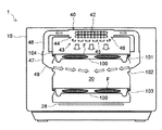
以下、本発明による加熱調理器の実施形態を図1−7に基づき説明する。図1は正面図、図2は加熱室の扉を開いた状態の正面図、図3は第1のトレイ使用状況を説明する模型的断面図、図4は第2のトレイ使用状況を説明する模型的断面図、図5は全体構成説明図、図6は部分拡大断面図、図7は制御ブロック図である。 Hereinafter, the embodiment of the heating cooker by this invention is described based on FIGS. 1-7. 1 is a front view, FIG. 2 is a front view of the heating chamber with the door open, FIG. 3 is a schematic cross-sectional view for explaining the first tray use state, and FIG. 4 is for explaining the second tray use state. FIG. 5 is a schematic sectional view, FIG. 5 is an explanatory diagram of the entire configuration, FIG. 6 is a partially enlarged sectional view, and FIG. 7 is a control block diagram.
加熱調理器1は直方体形状のキャビネット10を備える。キャビネット10の正面には扉11が設けられる。扉11は下端を中心に垂直面内で回動するものであり、上部のハンドル12を握って手前に引くことにより、図1に示す垂直な閉鎖状態から図2に示す水平な開放状態へと90゜姿勢変換させることができる。扉11は、耐熱ガラスをはめ込んだ透視部を備える中央部分11Cの左右に、金属製装飾板で仕上げられた左側部分11L及び右側部分11Rを対称的に配置した構成を備える。右側部分11Rには操作部13が設けられている。
The
扉11を開くと図2のようにキャビネット10の正面が露出する。扉11の中央部分11Cに対応する箇所には加熱室20が設けられている。扉11の左側部分11Lに対応する箇所には水タンク収納部80が設けられている。扉11の右側部分11Rに対応する箇所には特に開口部は設けられていないが、その箇所の内部に制御基板が配置されている。
When the
加熱室20は直方体形状で、扉11に面する正面側は全面的に開口部となっている。加熱室20の残りの面はステンレス鋼板で形成される。加熱室20の周囲には断熱対策が施される。
The
加熱調理器1は、食材を熱媒体で加熱するとともに、高周波を用いて加熱することも可能になっている。以下、主として図5を参照しつつ加熱の仕組みを説明する。
The
加熱室20の底部の下には高周波発生装置21が組み込まれている。すなわち加熱室の底部はガラスやセラミックなどの誘電体で形成され、その下にアンテナ室22が形成されている。アンテナ室22はアンテナ23を収容し、アンテナ23はアンテナモータ24によって水平面内で揺動する。アンテナ室22にはマグネトロン25より導波管26を通じて高周波が送り込まれ、送り込まれた高周波をアンテナ23が加熱室20内に供給する。マグネトロン25は高周波駆動電源27(図7参照)によって発振する。
A
加熱室20の底部の下には、高周波発生装置21の他、下部ヒータ28が配置されている。下部ヒータ28は後述する熱媒体ヒータと協働して加熱室20内の熱媒体を所定温度に加熱する。
In addition to the high-
加熱調理器1は熱媒体として過熱水蒸気または熱風を用いるものであり、熱媒体は外部循環路30を通って循環する。外部循環路30の始端となるのは、加熱室20の奥の側壁の上部に形成された吸込口31である。吸込口31は小径の透孔の集合からなる。
The
吸込口31に続くのは送風装置32である。送風装置32は加熱室20の奥の側壁の外面に取り付けられている。送風装置32は遠心ファン33及びこれを収容するファンケーシング34と、遠心ファン33を回転させるファンモータ35(図7参照)を備える。遠心ファン33としてはシロッコファンを用いる。ファンモータ35には高速回転が可能な直流モータを使用する。
A
ファンケーシング34から吐出された熱媒体はダクト36を通じて熱媒体生成装置40に送り込まれる。熱媒体生成装置40は、加熱室の天井部の上に形成された昇温室41の中に熱媒体ヒータ42を配置して構成されるものであり、平面的に見て天井部の中央部にあたる箇所に設けられる。熱媒体ヒータ42はシーズヒータからなる。
The heat medium discharged from the
熱媒体生成装置40で昇温された熱媒体は上方及び側方より噴流として加熱室20に供給される。その噴流を形成する仕組みにつき以下説明する。
The heat medium heated by the
加熱室20の上部には上部熱媒体供給口43が設けられる。上部熱媒体供給口43を構成するのは、昇温室41の底部となり、また加熱室20の天井部の一部ともなる噴気カバー44である。噴気カバー44は垂直断面が台形のドームを上下反転した形状であり、そこに形成された複数の噴気孔が噴流形成部を構成する。噴気カバー44の中央に広い面積を占める水平部には熱媒体を真下に噴出させる垂直噴気孔45が複数形成され、水平部を囲む斜面部には熱媒体を斜め下に噴出させる斜め噴気孔46が複数形成されている。
An upper heat
加熱室20の左右両側壁の外側には、左右対称的に側部熱媒体供給口47(図3参照)が設けられる。どちらの側部熱媒体供給口47にも、熱媒体生成装置40よりダクト48を通じて熱媒体が送り込まれる。側部熱媒体供給口47の加熱室20に面する側は開口となっており、そこから熱媒体が噴流となって噴き出す。すなわちこの箇所が噴流形成部となる。側部熱媒体供給口47の底部は噴流の方向を定めるガイド部49となっている。なお、側部熱媒体供給口47から加熱室20に流入する熱媒体のうち、少なくとも一部の成分は、側部熱媒体供給口47よりも下方向に向く。
Side heat medium supply ports 47 (see FIG. 3) are provided on the outer sides of the left and right side walls of the
熱媒体である過熱水蒸気のもととなる飽和水蒸気を生成するため、加熱調理器1は水蒸気発生装置60を備える。水蒸気発生装置60は中心線を垂直にして配置された筒型のポット61を備える。ポット61には耐熱性が求められるが、その条件を満たすかぎり、どのような材料で形成してもよい。金属でもよく、合成樹脂でもよい。セラミックの採用も可能である。異種材料を組み合わせてもよい。
The
ポット61の内部は円筒形の隔壁62により内室63と外室64に区画される。内室63と外室64は底部で連通している。外室64の中にはシーズヒータをコイル状に巻いた蒸気発生ヒータ65が配置されている。また外室64に対し、水蒸気供給管66の入口部が接続される。水蒸気供給管66の出口部はファンケーシング34の吸込側に接続される。
The inside of the
内室63に対し、給水管67とオーバーフロー管68が接続される。給水管67は水タンク収納部80に収納された水タンク81の水をポット61に注ぎ込むためのものであり、途中に給水ポンプ69が設けられている。ポット61の底部は漏斗状に成形され、そこから排水パイプ70が導出される。排水パイプ70の途中には排水バルブ71が設けられている。
A
給水ポンプ69は、直接水タンク81から水を吸い上げるのでなく、水タンク81が接続する中継タンク72から水を吸い上げるものである。水タンク81の底部からは水タンク収納部80の奥に向かって出口管82が突き出し、この出口管82が中継タンク72から横向きに突き出す入口管73に接続する。
The
水タンク81を水タンク収納部80から引き出し、出口管82が入口管73から離れたとき、そのままでは水タンク81内の水と中継タンク72内の水が流出してしまう。これを防ぐため、出口管82と入口管73にカップリングプラグ74a、74bを装着する。図5のように出口管82を入口管73に接続した状態では、カップリングプラグ74a、74bは互いに連結し、通水可能な状態になる。出口管82を入口管73から切り離せば、カップリングプラグ74a、74bはそれぞれ閉鎖状態になり、水タンク81と中継タンク72からの水の流出が止まる。
When the
給水管67は中継タンク72に上から入り込み、先端を中継タンク72の底部近くに届かせている。オーバーフロー管68は中継タンク72の上部に接続されている。排水管70は水タンク81の給水口83に接続されている。
The
ポット61の内部にはポット水位センサ75が配設され、中継タンク72には水位センサ76が配設される。ポット水位センサ75はポット61の天井部から垂下する1対の電極棒により構成され、水位センサ76は中継タンク72の天井部から垂下する計4本の電極棒により構成される。水位センサ76を構成する4本の電極棒の内、2本は他のものより長く、中継タンク72の底部近くまで届く。もう1本の電極棒はそれより短く、最後の1本の電極棒はそれよりもさらに短い。なおポット水位センサ75は蒸気発生ヒータ65より少し高い位置にある。
A pot
加熱室20には、そこから熱媒体を機外に逃がす排気路77が形成されている。ダクト36にも排気路78が形成される。排気路78の入口には電動式のダンパ79が設けられている。
The
加熱調理器1の動作制御を行うのは図7に示す制御装置90である。制御装置90はマイクロプロセッサ及びメモリを含み、所定のプログラムに従って加熱調理器1を制御する。制御状況は操作部13の中の表示部14に表示される。表示部14は例えば液晶パネルにより構成される。制御装置90には操作部13に配置した各種操作キーを通じて動作指令の入力を行う。操作部13には各種の音を出す音発生装置も配置されている。
The
制御装置90には、操作部13及び表示部14の他、アンテナモータ24、高周波駆動電源27、下部ヒータ28、ファンモータ35、熱媒体ヒータ42、蒸気発生ヒータ65、給水ポンプ69、排水バルブ71、ダンパ79、ポット水位センサ75、及び水位センサ76が接続される。この他、加熱室20内の温度を測定する温度センサ91と加熱室20内の湿度を測定する湿度センサ92が接続される。
In addition to the
食材Fは食材トレイ100に載置して加熱室20に挿入する。加熱室20の内部には、挿入された食材トレイ100を所定高さに支持するトレイ受けが設けられる。本実施形態では、加熱室20の両側壁に、食材トレイ100の端を係合させて食材トレイ100を水平に支持するトレイ受けが形成される。このトレイ受けを複数段設けたというのが本発明の眼目である。
The food F is placed on the
本実施形態では上から下まで3段にわたってトレイ受けを設ける。最上段の第1トレイ受け101は側部熱媒体供給口47より加熱室20に流入する側部熱媒体流より上の位置に食材トレイ100を支持する。中段の第2トレイ受け102は前記側部熱媒体流が上から吹きかけられる位置に食材トレイ100を支持する。最下段の第3トレイ受け103は第2トレイ受け102より下方に所定距離隔たった位置に食材トレイ100を支持する。
In the present embodiment, the tray receiver is provided in three stages from top to bottom. The uppermost
第2トレイ受け102は、それが支持する食材トレイ100上の食材Fを、側部熱媒体供給口47から噴出する熱媒体と、上部熱媒体供給口43から噴出する熱媒体の両方で調理することを計算して位置設定がなされる。上方からの熱媒体の噴流を勢い良く食材Fに衝突させることを考えると、第2トレイ受け102はある程度加熱室20の天井部に接近していることが望ましい。他方第1トレイ受け101の支持する食材トレイ100の上にもある程度の空間が必要である。このような訳で、第1トレイ受け101と第2トレイ受け102とは比較的間隔が接近した状態で配置されることになる。側部熱媒体供給口47を挟みつつ、第1トレイ受け101と第2トレイ受け102の間隔を無理なく接近させる方策については後述する。
The
第1、第2、第3のトレイ受け101、102、103を構成するのは、それぞれ加熱室20の側壁面から突き出すうね状の突部である。突部は正面から見た断面形状が三角形で、上面はほぼ水平になっている。第2トレイ受け102と第3トレイ受け103の突部は加熱室20の側壁に一体成形されているが、第1トレイ受け101の突部のみは側壁と別の部品に形成される。
The first, second, and
第1トレイ受け101の突部が形成されるのは側部熱媒体供給口47の開口の上部を覆うカバー104(図3、6参照)である。カバー104もステンレス鋼板製である。このように、側壁とは別部品であるカバー104に第1トレイ受け101を形成したので、第2トレイ受け102を加熱室20の天井部から適切な距離に形成し、側部熱媒体供給口47も機能発揮に必要な形状を確保しつつ、第1トレイ受け101も加熱室20の天井部から適切な位置に配置することができる。そして前述のように第1トレイ受け101と第2トレイ受け102の間隔を無理なく接近させることができる。
The protrusion of the
図6に見られるように、加熱室20の側壁を構成するステンレス鋼板は側部熱媒体供給口47を構成するステンレス鋼板を巻き込んでおり、これにより加熱室20の側壁には、側部熱媒体供給口47の箇所に凹部105が形成されている。カバー104の縁はこの凹部105に収容され、側壁表面から突き出さない。そのため、カバー104の縁に汚れが溜まらず、手入れが簡単である。
As shown in FIG. 6, the stainless steel plate constituting the side wall of the
加熱調理器1の動作は次の通りである。熱媒体として過熱水蒸気を使用する場合は、扉11を開け、水タンク81を水タンク収納部80から引き出し、給水口83より水タンク81内に水を入れる。十分に水を入れた水タンク81を水タンク収納部80に押し込み、所定位置にセットする。出口管82が中継タンク72の入口管73にしっかりと接続されたことを確認したうえで、食材トレイ100に載置した食材Fを加熱室20に入れ、扉11を閉じる。それから操作部13の操作キー群の中で必要なものを押して調理メニューの選択や各種設定を行い、調理をスタートさせる。
The operation of the
出口管82が入口管73に接続されると、水タンク81と中継タンク72が連通し、双方の水位が同じになる。このため、中継タンク72内の水位を測定する水位センサ76によって水タンク81内の水位も測定されることになる。水タンク81内の水量が選択された調理メニューを遂行するのに十分であれば、制御装置90は水蒸気の発生を開始する。水タンク81内の水量が選択された調理メニューを遂行するのに不十分であれば、制御装置90はその旨を警告報知として表示部14に表示する。そして水量不足が解消されるまで水蒸気の発生を開始しない。
When the
水蒸気の発生が可能な状態になると、給水ポンプ69が運転を開始し、水蒸気発生装置60への給水が始まる。この時、排水バルブ71は閉じている。
When the water vapor can be generated, the
水は容器61の底の方から溜まって行く。一定量の水が給水されたらそこで給水は停止する。なお、制御系の故障などで給水ポンプ69の運転が止まらないようなことがあると、容器61内の水位は所定レベルを超えても上昇し続けるが、溢水レベルに達すれば、容器61内の水はオーバーフロー管68を通じて中継タンク72に戻る。従って容器61から水が溢れるようなことはない。
Water accumulates from the bottom of the
給水停止後、蒸気発生ヒータ65への通電が開始される。蒸気発生ヒータ65はポット61内の水を直接加熱する。ポット61内の水が沸騰し、飽和水蒸気が発生したら、蒸気発生ヒータ52への通電が停止される。そして送風装置32及び熱媒体ヒータ42への通電が開始される。送風装置32は吸込口31を通じて加熱室20内の空気を吸い込む。また水蒸気供給管66を通じて水蒸気発生装置60より飽和水蒸気を吸い込む。送風装置32が吐出する空気と飽和水蒸気の混合気体はダクト36を通じて熱媒体生成装置40に送り込まれる。この時ダンパ79は排気路78の入口を閉ざしている。
After the water supply is stopped, energization to the
熱媒体生成装置40に入った飽和水蒸気は熱媒体ヒータ42により300℃にまで熱せられ、過熱水蒸気となる。過熱水蒸気は上部熱媒体供給口43より下向き及び斜め下向きの噴流として加熱室20に噴き出す。過熱水蒸気の一部はダクト48を通じて側部熱媒体供給口47に送り込まれ、側部熱媒体供給口47より、やや下向きになった側部熱媒体流として加熱室20に噴き出す。これらの過熱水蒸気によってもたらされる熱で加熱室20内の食材Fは加熱される。
The saturated steam that has entered the heat
過熱水蒸気による加熱では、食材Fは、対流伝熱(水蒸気の比熱0.48cal/g/℃)に加えて、表面で過熱水蒸気が凝縮する際に生じる凝縮熱(潜熱)によっても加熱される。凝縮熱は539cal/gと大きいため、食材Fに大量の熱を与えることができ、食材Fは急速に加熱される。また加熱水蒸気は食材Fの中で温度の低い部分に優先的に凝縮するので、加熱ムラが少なくなり、仕上がりの良い加熱調理ができる。 In the heating with superheated steam, the food material F is heated not only by convection heat transfer (specific heat of steam: 0.48 cal / g / ° C.) but also by condensation heat (latent heat) generated when the superheated steam condenses on the surface. Since the heat of condensation is as large as 539 cal / g, a large amount of heat can be given to the food material F, and the food material F is heated rapidly. Moreover, since heating steam condenses preferentially in the part with low temperature in the foodstuff F, a heating nonuniformity decreases and cooking with sufficient finish can be performed.
過熱水蒸気は、表面温度の低い食材Fに付着すると直ちに凝縮して凝縮水となり、凝縮熱で大量の熱を伝達する。その後食材Fから水分が蒸発し始め、復元過程を経てから乾燥が始まる。従って食材Fは、内部に水分を保持しつつ、表面はパリッとした仕上がりになる。また熱風による調理に比べ、脱油効果、減塩効果、ビタミンC破壊抑制効果、油脂酸化抑制効果ともに大きい。 As soon as the superheated steam adheres to the food F having a low surface temperature, it condenses and becomes condensed water, and a large amount of heat is transferred by the condensation heat. Thereafter, moisture begins to evaporate from the food material F, and drying begins after a restoration process. Therefore, the food F has a crisp finish on the surface while retaining moisture therein. Moreover, compared with cooking with hot air, the deoiling effect, the salt reducing effect, the vitamin C destruction inhibiting effect, and the fat oxidation inhibiting effect are all great.
過熱水蒸気による調理の際、熱媒体ヒータ42への通電が連続的に行われる訳ではない。時々下部ヒータ28への通電に切り替えられる。ちなみにヒータの消費電力は、例えば、蒸気発生ヒータ65が1300W、熱媒体ヒータ42も1300W、下部ヒータ28が700Wといった具合に設定される。一般家庭の電力事情を考えた場合、これらのヒータを2個以上同時に通電対象とすることはできないので、デューティー制御により時分割で順次通電対象を切り替えて最適結果が得られるようにしている。これは熱風による加熱の場合も同様である。
During cooking with superheated steam, the
加熱室20内の水蒸気量が多くなった場合、余剰の水蒸気は排気路77から機外に放出される。その水蒸気が加熱調理器1の周辺に結露して錆やカビを発生させるといったことのないよう、機外に出す前に水蒸気を凝縮させ、ドレンの形で排出する仕組みを採用してもよい。
When the amount of water vapor in the
水蒸気発生装置60で蒸気を発生し続けていると、ポット61内の水位が低下する。水位が所定レベルに低下したことをポット水位センサ75が検知すると、制御装置90は給水ポンプ69の運転を再開する。給水ポンプ69は中継タンク72内の水を吸い上げ、ポット61に一定量の水を補充する。水補給完了後、制御装置90は給水ポンプ69の運転を再び停止する。
If steam is continuously generated by the
調理終了後、制御装置90が表示部14にその旨の表示を出し、また合図音を鳴らす。調理終了を音と表示により知った使用者は扉11を開け、加熱室20から食材Fを取り出す。それ以後の調理の予定がなければ排水バルブ71が開き、ポット61内の水は水タンク81に戻される。
After cooking is completed, the
熱媒体として熱風を使用する調理メニューを選択した場合は、水タンク81内の水量を問うことなく、すぐに熱媒体ヒータ42への通電と、送風装置32の運転が開始される。今度は熱風の噴流で食材Fが加熱されることになる。過熱水蒸気による加熱の場合と同様、熱媒体ヒータ42と下部ヒータ28は時分割で通電制御される。なお熱風による調理の場合、従来から用いているオーブン調理用のレシピを採用することができる。
When a cooking menu that uses hot air as the heat medium is selected, energization of the
過熱水蒸気または熱風で調理を行っている際に扉11を開けると、使用者の方に過熱水蒸気または熱風が流れる可能性がある。調理終了後も同様である。そのため、高温の熱媒体が循環している期間中に扉11が開けられたときは、ダンパ79が動作して排気路78の入口を開き、排気路78に高温熱媒体を誘導するようになっている。
If the
高周波加熱による調理メニューを選択した場合は、高周波発生装置21が駆動される。高周波発生装置21は、単独でも使用され得るし、過熱水蒸気または熱風との併用も可能である。
When the cooking menu by high frequency heating is selected, the
前述の通り、食材Fは食材トレイ100に載置した状態で加熱室20に入れられるが、その時どのトレイ受けに食材トレイ100を支持させるかは調理メニューによって異なる。過熱水蒸気による調理を選択したときは食材トレイ100は第2トレイ受け102に支持されるべきものであり、その旨が表示部14に指示として表示される。
As described above, the food F is placed in the
第2トレイ受け102で食材トレイ100を支持する場合、食材トレイ100の上にはステンレス鋼線製の食材支持網110を置き、食材Fをトレイ面から浮かせて支持する。第1トレイ受け101または第3トレイ受け103に支持された食材トレイ100においても食材支持網110は効用を発揮する。しかしながら第2トレイ受け102に支持された食材トレイ100にあっては、側部熱媒体供給口47から斜め下に噴出する側部熱媒体流を食材Fの下に回り込ませるため、少なくともこの場合の食材支持網110の使用はほぼ必須となる。
When the
第2トレイ受け102に支持された食材トレイ100の上の食材Fには、上部熱媒体供給口43より下向きに過熱水蒸気が吹き付けられる。また側部熱媒体供給口47からの過熱水蒸気の側部熱媒体流が食材トレイ100の上面に当たって上向きに方向を変えることにより、食材Fの下面にも過熱水蒸気が吹き付けられる。このように上下から過熱水蒸気が吹き付けられることにより、食材Fは対流伝熱による熱と凝縮熱(潜熱)を満遍なく受け取り、効率的に加熱される。
Superheated steam is sprayed downward from the upper heat
第2トレイ受け102に支持された食材トレイ100の上の食材Fを熱風で調理することも勿論可能である。食材支持網110で食材Fを浮かせておけば、食材Fは上下からの熱風で満遍なく加熱される。
It is of course possible to cook the food F on the
食材支持網110を使用せず、直接食材トレイ100の上に食材Fを載置する調理方法を採用すれば、側部熱媒体供給口47からの過熱水蒸気または熱風の側部熱媒体流は食材Fに直接吹き付けられることになる。
If a cooking method in which the food F is placed directly on the
熱風による調理では、第1トレイ受け101に食材トレイ100を支持させて調理を行うことができる。この場合、上部熱媒体供給口43からの熱風の噴流が食材Fに吹き付けるとともに、食材トレイ100より下の加熱室20全体に、側部熱媒体供給口47より熱風が供給されることになる。また熱風による調理の場合には第3トレイ受け103に食材トレイ100を支持させて調理を行うこともできる。このときは、上部熱媒体供給口43と側部熱媒体供給口47からの熱風の噴流が加熱室20の中の広い空間に拡散するので、均一なコンベクション調理が可能になる。
In cooking with hot air, cooking can be performed with the
熱風による調理では、食材トレイ100を2枚用いた調理も可能である。この場合、食材トレイ100の1枚は第1トレイ受け101に支持させ、もう1枚は第3トレイ受け103に支持させて、上下2段とする。その状況を図4に示す。第1トレイ受け101に支持された食材トレイ100の上の食材Fは、上部熱媒体供給口43から吹き下ろす熱風の噴流と、側部熱媒体供給口47からその食材トレイ100の下に吹き込まれる熱風の側部熱媒体流を主たる熱源として加熱される。第3トレイ受け103に支持された食材トレイ100の上の食材Fは、側部熱媒体供給口47から吹き込まれる熱風の側部熱媒体流と、下部ヒータ28を主たる熱源として加熱される。上部熱媒体供給口43と側部熱媒体供給口47の間の空気量配分を調整し、また熱媒体ヒータ42と下部ヒータ28の間の電力負荷配分を調整することにより、第1トレイ受け101側の食材Fと第3トレイ受け103側の食材Fとの間で調理具合にむらが出ないようにすることができる。
In cooking with hot air, cooking using two
以上本発明の実施形態につき説明したが、この他、発明の主旨を逸脱しない範囲でさらに種々の変更を加えて実施することが可能である。 Although the embodiments of the present invention have been described above, other various modifications can be made without departing from the spirit of the present invention.
本発明は、家庭用、業務用を問わず、熱媒体で食材の調理を行う加熱調理器全般に利用可能である。 INDUSTRIAL APPLICABILITY The present invention can be used in general cooking devices that cook food with a heat medium regardless of household use or business use.
1 加熱調理器
13 操作部
14 表示部
20 加熱室
40 熱媒体生成装置
43 上部熱媒体供給口
47 側部熱媒体供給口
100 食材トレイ
101 第1トレイ受け
102 第2トレイ受け
103 第3トレイ受け
104 カバー
105 段部
110 食材支持網
F 食材
DESCRIPTION OF
Claims (3)
前記側部熱媒体供給口を前記側壁の中間の高さに設けると共に、前記熱媒体を当該供給口から斜め下方向に向かって噴出するように構成し、
前記加熱室に載置する食材トレイを保持するために、前記側部熱媒体供給口よりも上の位置に第1トレイ受けを、また前記側部熱媒体供給口よりも下の位置であって、当該側部熱媒体供給口に近接して第2トレイ受けをそれぞれ設けると共に、
前記加熱室の前記第2トレイよりも少なくとも上方に前記熱媒体の吸込口を設け、
前記食材トレイはその外周端部が加熱室周側壁にほぼ接する大きさとし、
前記第2トレイ受けに前記食材トレイを載置することにより、当該食材トレイより上部の加熱室内において前記過熱水蒸気による加熱調理を可能とし、
前記第2トレイ受けに前記食材トレイを載置しない場合は、加熱室内全体において熱風による加熱調理を行なうようにしたことを特徴とする加熱調理器。 A heating heater is provided, and hot air or superheated steam at 100 ° C. or higher is selectively used as a heating medium from an upper heating medium supply port provided in the upper part of the heating chamber and a side heating medium supply port provided in the side wall of the heating chamber. In a heating cooker that flows into the heating chamber and circulates ,
The side heat medium supply port is provided at an intermediate height of the side wall, and the heat medium is configured to be ejected obliquely downward from the supply port,
To hold the food tray to be placed on the heating chamber, the first tray receives the position above the said side heat medium supply ports and a position below the said side heat medium supply ports In addition, a second tray receiver is provided in the vicinity of the side heat medium supply port ,
A suction port for the heat medium is provided at least above the second tray in the heating chamber;
The food tray has a size such that the outer peripheral end is substantially in contact with the heating chamber peripheral side wall,
By placing the food tray on the second tray receiver, it is possible to cook with the superheated steam in the heating chamber above the food tray,
When the food tray is not placed on the second tray receptacle, the cooking device is characterized in that cooking is performed by hot air in the entire heating chamber .
The cooking device according to claim 1, further comprising an operation unit and a display unit, wherein when a cooking menu is selected by the operation unit, a tray receiver used in the cooking menu is displayed on the display unit. vessel.
Priority Applications (1)
| Application Number | Priority Date | Filing Date | Title |
|---|---|---|---|
| JP2006194372A JP4610530B2 (en) | 2006-07-14 | 2006-07-14 | Cooker |
Applications Claiming Priority (1)
| Application Number | Priority Date | Filing Date | Title |
|---|---|---|---|
| JP2006194372A JP4610530B2 (en) | 2006-07-14 | 2006-07-14 | Cooker |
Publications (3)
| Publication Number | Publication Date |
|---|---|
| JP2008020162A JP2008020162A (en) | 2008-01-31 |
| JP2008020162A5 JP2008020162A5 (en) | 2008-10-16 |
| JP4610530B2 true JP4610530B2 (en) | 2011-01-12 |
Family
ID=39076232
Family Applications (1)
| Application Number | Title | Priority Date | Filing Date |
|---|---|---|---|
| JP2006194372A Expired - Fee Related JP4610530B2 (en) | 2006-07-14 | 2006-07-14 | Cooker |
Country Status (1)
| Country | Link |
|---|---|
| JP (1) | JP4610530B2 (en) |
Families Citing this family (4)
| Publication number | Priority date | Publication date | Assignee | Title |
|---|---|---|---|---|
| KR101544451B1 (en) * | 2008-07-21 | 2015-08-13 | 엘지전자 주식회사 | Oven |
| JP5744496B2 (en) * | 2010-12-09 | 2015-07-08 | シャープ株式会社 | Cooker |
| JP5620600B1 (en) * | 2014-03-11 | 2014-11-05 | アイリスオーヤマ株式会社 | Cooker |
| JP5947951B2 (en) * | 2015-04-28 | 2016-07-06 | シャープ株式会社 | Cooker |
Citations (4)
| Publication number | Priority date | Publication date | Assignee | Title |
|---|---|---|---|---|
| JPS57201406U (en) * | 1981-06-19 | 1982-12-22 | ||
| JP2005083739A (en) * | 2003-09-09 | 2005-03-31 | Samsung Electronics Co Ltd | Steam cooker |
| JP2006046863A (en) * | 2004-08-06 | 2006-02-16 | Sharp Corp | Superheated steam cooker |
| JP2006084082A (en) * | 2004-09-15 | 2006-03-30 | Sharp Corp | Superheated steam cooking device |
-
2006
- 2006-07-14 JP JP2006194372A patent/JP4610530B2/en not_active Expired - Fee Related
Patent Citations (4)
| Publication number | Priority date | Publication date | Assignee | Title |
|---|---|---|---|---|
| JPS57201406U (en) * | 1981-06-19 | 1982-12-22 | ||
| JP2005083739A (en) * | 2003-09-09 | 2005-03-31 | Samsung Electronics Co Ltd | Steam cooker |
| JP2006046863A (en) * | 2004-08-06 | 2006-02-16 | Sharp Corp | Superheated steam cooker |
| JP2006084082A (en) * | 2004-09-15 | 2006-03-30 | Sharp Corp | Superheated steam cooking device |
Also Published As
| Publication number | Publication date |
|---|---|
| JP2008020162A (en) | 2008-01-31 |
Similar Documents
| Publication | Publication Date | Title |
|---|---|---|
| JP3781759B2 (en) | Steam cooker | |
| US7802564B2 (en) | Steam cooking apparatus | |
| JP2008008539A (en) | Heating cooker | |
| JP4610530B2 (en) | Cooker | |
| JP4721996B2 (en) | Cooker | |
| JP2008025894A (en) | Cooker | |
| JP2010054097A (en) | Heating cooker | |
| JP4721970B2 (en) | Food support unit for heating cooker and heating cooker including the same | |
| JP4408760B2 (en) | Steam cooker | |
| JP5052988B2 (en) | Steam cooker | |
| JP6267309B2 (en) | Steam cooker | |
| JP5938291B2 (en) | Cooker | |
| JP4381187B2 (en) | Steam cooker | |
| JP2005241188A (en) | Steam cooking device and steam generator | |
| JP2005195248A (en) | Steam cooker | |
| JP4398798B2 (en) | Steam cooker | |
| JP4222978B2 (en) | Cooker | |
| JP4416610B2 (en) | Superheated steam cooker | |
| JP2008032266A (en) | Vapor generating device and heating cooker mounted therewith | |
| JP6043414B2 (en) | Steam cooker | |
| JP5797729B2 (en) | Steam cooker | |
| JP4987635B2 (en) | Steam cooker | |
| JP2009041818A (en) | Vapor cooker | |
| JP4583816B2 (en) | Steam cooker | |
| JP2007032889A (en) | Heating cooker |
Legal Events
| Date | Code | Title | Description |
|---|---|---|---|
| RD01 | Notification of change of attorney |
Free format text: JAPANESE INTERMEDIATE CODE: A7421 Effective date: 20071128 |
|
| A521 | Written amendment |
Free format text: JAPANESE INTERMEDIATE CODE: A523 Effective date: 20080903 |
|
| A621 | Written request for application examination |
Free format text: JAPANESE INTERMEDIATE CODE: A621 Effective date: 20080903 |
|
| A977 | Report on retrieval |
Free format text: JAPANESE INTERMEDIATE CODE: A971007 Effective date: 20100706 |
|
| A131 | Notification of reasons for refusal |
Free format text: JAPANESE INTERMEDIATE CODE: A131 Effective date: 20100713 |
|
| A521 | Written amendment |
Free format text: JAPANESE INTERMEDIATE CODE: A523 Effective date: 20100913 |
|
| TRDD | Decision of grant or rejection written | ||
| A01 | Written decision to grant a patent or to grant a registration (utility model) |
Free format text: JAPANESE INTERMEDIATE CODE: A01 Effective date: 20101012 |
|
| A01 | Written decision to grant a patent or to grant a registration (utility model) |
Free format text: JAPANESE INTERMEDIATE CODE: A01 |
|
| A61 | First payment of annual fees (during grant procedure) |
Free format text: JAPANESE INTERMEDIATE CODE: A61 Effective date: 20101012 |
|
| FPAY | Renewal fee payment (event date is renewal date of database) |
Free format text: PAYMENT UNTIL: 20131022 Year of fee payment: 3 |
|
| R150 | Certificate of patent or registration of utility model |
Free format text: JAPANESE INTERMEDIATE CODE: R150 Ref document number: 4610530 Country of ref document: JP Free format text: JAPANESE INTERMEDIATE CODE: R150 |
|
| LAPS | Cancellation because of no payment of annual fees | ||
| S531 | Written request for registration of change of domicile |
Free format text: JAPANESE INTERMEDIATE CODE: R313531 |
|
| R350 | Written notification of registration of transfer |
Free format text: JAPANESE INTERMEDIATE CODE: R350 |