JP4987635B2 - Steam cooker - Google Patents
Steam cooker Download PDFInfo
- Publication number
- JP4987635B2 JP4987635B2 JP2007230149A JP2007230149A JP4987635B2 JP 4987635 B2 JP4987635 B2 JP 4987635B2 JP 2007230149 A JP2007230149 A JP 2007230149A JP 2007230149 A JP2007230149 A JP 2007230149A JP 4987635 B2 JP4987635 B2 JP 4987635B2
- Authority
- JP
- Japan
- Prior art keywords
- steam
- cooking
- heater
- heating chamber
- heated
- Prior art date
- Legal status (The legal status is an assumption and is not a legal conclusion. Google has not performed a legal analysis and makes no representation as to the accuracy of the status listed.)
- Active
Links
Images


Landscapes
- Electric Stoves And Ranges (AREA)
Description
本発明は、加熱室内に蒸気を噴出して被加熱物の調理を行う蒸気調理器に関する。 The present invention relates to a steam cooker that cooks an object to be heated by jetting steam into a heating chamber.
従来の蒸気調理器は特許文献1に開示されている。この蒸気調理器は過熱蒸気を加熱媒体とし、加熱室内に配された受皿上に被加熱物が載置されて被加熱物に応じた料理メニューが選択される。加熱室の側方には水タンクが配され、水タンクから給水路を介して蒸気発生装置に給水される。蒸気発生装置は供給された水によって蒸気を生成して蒸気昇温装置に送出する。蒸気昇温装置は蒸気を更に加熱して過熱蒸気を生成し、過熱蒸気を加熱室に噴出する。そして、調理にメニューに応じた調理シーケンスに従って低酸素状態で被加熱物の調理が行われる。
A conventional steam cooker is disclosed in
これにより、被加熱物の酸化を防止し、脂質の酸化による臭いの発生や味の劣化を防止して良好な調理を行うことができる。また、被加熱物に含まれる油脂が溶解して蒸気の凝縮水とともに流下し、被加熱物を脱油して健康的な調理を行うことができる。 Thereby, oxidation of a to-be-heated material is prevented, generation | occurrence | production of the smell by oxidation of lipid, deterioration of a taste can be prevented, and favorable cooking can be performed. Moreover, the fats and oils contained in a to-be-heated material melt | dissolve and flow down with the condensed water of a vapor | steam, and a to-be-heated material can be deoiled and healthy cooking can be performed.
しかしながら、上記従来の蒸気調理器によると、調理開始時の加熱室が高温の場合に通常の調理シーケンスで調理すると被加熱物の表面が焦げてしまう。これにより、調理の仕上り状態が悪くなる問題があった。 However, according to the conventional steam cooker, when the heating chamber at the start of cooking is hot, cooking with a normal cooking sequence will burn the surface of the object to be heated. Thereby, there existed a problem which the finishing state of cooking worsened.
特許文献2には調理開始時の加熱室が高温で所定温度に到達する時間が短い場合に調理シーケンスを補正して調理時間を短縮する加熱調理器が開示される。しかしながら、蒸気調理器において特許文献2と同様に調理時間を短縮すると、脱油効果が低下する問題がある。 Patent Document 2 discloses a heating cooker that corrects the cooking sequence and shortens the cooking time when the heating chamber at the start of cooking is at a high temperature and the time to reach a predetermined temperature is short. However, if the cooking time is shortened in the steam cooker as in Patent Document 2, there is a problem that the deoiling effect is lowered.
本発明は、脱油効果を低下させることなく調理の仕上り状態を向上できる蒸気調理器を提供することを目的とする。 An object of this invention is to provide the steam cooker which can improve the finishing state of cooking, without reducing the deoiling effect.
上記目的を達成するために本発明は、蒸気を発生する蒸気発生ヒータと、前記蒸気発生ヒータで発生した蒸気を昇温して過熱蒸気を生成するとともに加熱室内の蒸気を循環して加熱する蒸気加熱ヒータとを備え、前記加熱室内に供給された蒸気を用いて被加熱物を調理する蒸気調理器において、前記蒸気発生ヒータの供給電力を前記蒸気加熱ヒータの供給電力よりも大きくして被加熱物を調理する第1調理工程と、前記蒸気発生ヒータの供給電力を前記蒸気加熱ヒータの供給電力よりも小さくして被加熱物を調理する第2調理工程とを有するとともに、調理開始時の前記加熱室が高温の時に低温の時よりも第2調理工程の時間を短縮したことを特徴としている。 In order to achieve the above object, the present invention provides a steam generating heater that generates steam, and steam that heats the steam generated by the steam generating heater to generate superheated steam and circulates and heats the steam in the heating chamber. A steam cooker for cooking an object to be heated using steam supplied into the heating chamber, wherein the power to be supplied to the steam generating heater is larger than the power to be supplied to the steam heating heater. A first cooking step of cooking an object, and a second cooking step of cooking the article to be heated by making the supply power of the steam generating heater smaller than the supply power of the steam heating heater, and at the start of cooking It is characterized in that the time of the second cooking step is shortened when the heating chamber is hot than when it is cold.
この構成によると、蒸気発生ヒータ及び蒸気加熱ヒータの駆動時には給水タンク等から蒸気発生ヒータに水が供給され、蒸気が発生する。発生した蒸気は蒸気加熱ヒータで更に昇温され、100℃よりも高温の過熱蒸気が生成される。過熱蒸気は加熱室に供給され、循環して蒸気加熱ヒータにより加熱される。これにより、高温の過熱蒸気による調理が行われる。 According to this configuration, when the steam generating heater and the steam heating heater are driven, water is supplied from the water supply tank or the like to the steam generating heater to generate steam. The generated steam is further heated by a steam heater, and superheated steam having a temperature higher than 100 ° C. is generated. The superheated steam is supplied to the heating chamber, circulates and is heated by the steam heater. Thereby, cooking by high temperature superheated steam is performed.
調理を開始すると加熱室の温度が検知され、加熱室の温度に応じて調理シーケンスを補正して第2調理工程の時間が可変される。調理シーケンスが決定されると蒸気発生ヒータの供給電力が蒸気加熱ヒータの供給電力よりも大きい第1調理工程が行われる。これにより、大量の過熱蒸気を加熱室に供給して調理が行われる。尚、蒸気加熱ヒータを停止した場合は大量の飽和蒸気を加熱室に供給して調理が行われる。被加熱物は大量の蒸気の潜熱によって内部温度が急激に上昇し、第2調理工程に切り替えられる。 When cooking is started, the temperature of the heating chamber is detected, the cooking sequence is corrected according to the temperature of the heating chamber, and the time of the second cooking step is varied. When the cooking sequence is determined, a first cooking step is performed in which the supply power of the steam generating heater is larger than the supply power of the steam heating heater. Thereby, cooking is performed by supplying a large amount of superheated steam to the heating chamber. When the steam heater is stopped, cooking is performed by supplying a large amount of saturated steam to the heating chamber. The internal temperature of the object to be heated suddenly rises due to the latent heat of a large amount of steam, and is switched to the second cooking step.
第2調理工程では蒸気発生ヒータの供給電力を蒸気加熱ヒータの供給電力よりも小さく設定される。これにより、循環により蒸気加熱ヒータで加熱された過熱蒸気または飽和蒸気によって被加熱物が調理される。第2調理工程は調理開始時の加熱室が所定温度よりも低温の場合は標準の調理時間で行われ、高温の場合は調理時間が短縮される。第2調理工程で被加熱物は主に表面が加熱され、所望の内部温度に維持されるとともに表面に焼き色が付けられて調理が完了する。 In the second cooking step, the supply power of the steam generating heater is set smaller than the supply power of the steam heating heater. As a result, the object to be heated is cooked by the superheated steam or saturated steam heated by the steam heater by circulation. The second cooking step is performed with a standard cooking time when the heating chamber at the start of cooking is lower than a predetermined temperature, and when the temperature is high, the cooking time is shortened. In the second cooking step, the surface of the object to be heated is mainly heated to maintain the desired internal temperature, and the surface is baked to complete cooking.
また本発明は上記構成の蒸気調理器において、前記蒸気発生ヒータにより加熱される水を貯水するポットを有し、調理開始時の前記ポットの水温が高温の時に低温の時よりも第1調理工程の時間を短縮したことを特徴としている。この構成によると、調理を開始するとポットの水温が検知され、水温に応じて調理シーケンスを補正して第1調理工程の時間が可変される。調理シーケンスが決定されると第1調理工程が行われる。第1調理工程は調理開始時のポットの水温が所定温度よりも低温の場合は標準の調理時間で行われ、高温の場合は調理時間が短縮される。 In the steam cooker having the above-described configuration, the present invention has a pot for storing water heated by the steam generating heater, and the first cooking step is performed when the temperature of the pot at the start of cooking is high when the water temperature is low than when the temperature is low. It is characterized by shortening the time. According to this configuration, when cooking is started, the water temperature of the pot is detected, the cooking sequence is corrected according to the water temperature, and the time of the first cooking process is varied. When the cooking sequence is determined, the first cooking process is performed. The first cooking step is performed with a standard cooking time when the water temperature of the pot at the start of cooking is lower than a predetermined temperature, and when the temperature is high, the cooking time is shortened.
また本発明は上記構成の蒸気調理器において、調理開始時の前記加熱室が高温の時に低温の時よりも第1調理工程の前記蒸気発生ヒータの供給電力を大きくして前記蒸気加熱ヒータの供給電力を小さくしたことを特徴としている。この構成によると、調理開始時の加熱室の温度に応じて調理シーケンスを補正して第1調理工程の加熱条件が可変される。調理シーケンスが決定されると第1調理工程が行われる。第1調理工程では調理開始時の加熱室が低温の場合は蒸気発生ヒータ及び蒸気加熱ヒータが標準の供給電力で駆動される。調理開始時の加熱室が高温の場合は蒸気発生ヒータが標準よりも供給電力を大きくして駆動され、蒸気加熱ヒータが標準よりも供給電力を小さくして駆動される。 According to the present invention, in the steam cooker having the above-described configuration, when the heating chamber at the start of cooking is at a high temperature, the supply power of the steam generating heater in the first cooking step is made larger than when the heating chamber is at a low temperature. It is characterized by low power. According to this structure, the cooking sequence is corrected according to the temperature of the heating chamber at the start of cooking, and the heating conditions of the first cooking step are varied. When the cooking sequence is determined, the first cooking process is performed. In the first cooking step, when the heating chamber at the start of cooking is at a low temperature, the steam generating heater and the steam heating heater are driven with standard supply power. When the heating chamber at the start of cooking is at a high temperature, the steam generating heater is driven with a larger supply power than the standard, and the steam heater is driven with a smaller supply power than the standard.
また本発明は、蒸気を発生する蒸気発生ヒータと、前記蒸気発生ヒータで発生した蒸気を昇温して過熱蒸気を生成するとともに加熱室内の蒸気を循環して加熱する蒸気加熱ヒータとを備え、前記加熱室内に供給された蒸気を用いて被加熱物を調理する蒸気調理器において、前記蒸気発生ヒータの供給電力を前記蒸気加熱ヒータの供給電力よりも大きくして被加熱物を調理する第1調理工程と、前記蒸気発生ヒータの供給電力を前記蒸気加熱ヒータの供給電力よりも小さくして被加熱物を調理する第2調理工程とを有するとともに、調理開始時の前記加熱室が高温の時に低温の時よりも第2調理工程の前記蒸気加熱ヒータの供給電力を下げたことを特徴としている。 The present invention also includes a steam generating heater that generates steam, and a steam heater that circulates and heats the steam in the heating chamber while heating the steam generated in the steam generating heater to generate superheated steam. In the steam cooker that cooks the object to be heated using the steam supplied into the heating chamber, the first power for cooking the object to be heated by making the supply power of the steam generating heater larger than the supply power of the steam heating heater. A cooking step and a second cooking step of cooking the article to be heated by making the supply power of the steam generating heater smaller than the supply power of the steam heater, and when the heating chamber at the start of cooking is at a high temperature It is characterized in that the power supplied to the steam heater in the second cooking step is lowered than when the temperature is low.
この構成によると、調理を開始すると加熱室の温度が検知され、加熱室の温度に応じて調理シーケンスを補正して第2調理工程の蒸気加熱ヒータの供給電力が可変される。調理シーケンスが決定されると蒸気発生ヒータの供給電力が蒸気加熱ヒータの供給電力よりも大きい第1調理工程が行われる。第2調理工程では調理開始時の加熱室が低温の時に蒸気発生ヒータの供給電力が蒸気加熱ヒータの供給電力よりも小さくしてそれぞれ駆動される。調理開始時の加熱室が高温の場合は低温の場合よりも蒸気加熱ヒータの供給電力を小さくして駆動される。 According to this configuration, when cooking is started, the temperature of the heating chamber is detected, the cooking sequence is corrected according to the temperature of the heating chamber, and the power supplied to the steam heater in the second cooking step is varied. When the cooking sequence is determined, a first cooking step is performed in which the supply power of the steam generating heater is larger than the supply power of the steam heating heater. In the second cooking step, when the heating chamber at the start of cooking is at a low temperature, the supply power of the steam generating heater is made smaller than the supply power of the steam heating heater, and each is driven. When the heating chamber at the start of cooking is at a high temperature, the steam heater is driven with a smaller power supply than at a low temperature.
また本発明は上記構成の蒸気調理器において、前記加熱室内の蒸気を循環する送風ファンを設け、調理開始時に前記送風ファンを駆動した後に前記加熱室の温度を検知したことを特徴としている。 In the steam cooker having the above-described configuration, the present invention is characterized in that a blower fan that circulates the steam in the heating chamber is provided, and the temperature of the heating chamber is detected after the blower fan is driven at the start of cooking.
また本発明は、第2調理工程で前記蒸気発生ヒータを停止したことを特徴としている。 Further, the present invention is characterized in that the steam generating heater is stopped in the second cooking step.
また本発明は上記構成の蒸気調理器において、前記蒸気加熱ヒータの輻射熱によって被加熱物を加熱することを特徴としている。この構成によると、蒸気加熱ヒータは例えば加熱室の天面に配され、蒸気加熱ヒータの輻射熱が被加熱物に照射されて加熱調理が行われる。 In the steam cooker having the above-described configuration, the present invention is characterized in that an object to be heated is heated by radiant heat of the steam heater. According to this configuration, the steam heater is disposed, for example, on the top surface of the heating chamber, and the object to be heated is irradiated with the radiant heat of the steam heater to perform cooking.
本発明によると、蒸気発生ヒータの供給電力が蒸気加熱ヒータの供給電力よりも大きい第1調理工程を有するので、大量の蒸気の潜熱によって被加熱物の内部温度を急速に上昇させることができる。これにより、早期に被加熱物の内部温度を油脂溶融温度帯よりも高温にして脱油を充分行うことができる。 According to the present invention, since the supply power of the steam generating heater is higher than the supply power of the steam heating heater, the internal temperature of the object to be heated can be rapidly increased by the latent heat of a large amount of steam. Thereby, the internal temperature of the article to be heated can be made higher than the fat melting temperature zone at an early stage to sufficiently perform deoiling.
また、第1調理工程から蒸気発生ヒータの供給電力を蒸気加熱ヒータの供給電力よりも小さくした第2調理工程に切り替えるので、被加熱物を所望の内部温度に維持するとともに表面に焼き色を付けて調理を完了させることができる。この時、調理開始時の加熱室が高温の時に第2調理工程の時間を短縮したので、被加熱物表面の焦げを防止して調理の仕上り状態を向上することができる。更に、調理時間を短縮することができる。 In addition, since the supply power of the steam generating heater is switched from the first cooking process to the second cooking process in which the supply power of the steam heating heater is smaller than that of the steam heating heater, the object to be heated is maintained at a desired internal temperature and the surface is colored. Cooking can be completed. At this time, since the time of the second cooking step is shortened when the heating chamber at the start of cooking is at a high temperature, the surface of the object to be heated can be prevented from being burned and the finished state of cooking can be improved. Furthermore, cooking time can be shortened.
また本発明によると、調理開始時のポットの水温が高温の時に第1調理工程の時間を短縮したので、蒸気の供給が早期に開始されるため被加熱物の内部温度を充分上昇させて良好な仕上り状態が得られるとともに調理時間を短縮することができる。 Further, according to the present invention, since the time of the first cooking step is shortened when the pot water temperature at the start of cooking is high, the supply of steam is started early, so that the internal temperature of the heated object can be sufficiently increased. As a result, the cooking time can be shortened.
また本発明によると、調理開始時の加熱室が高温の時に第1調理工程の蒸気加熱ヒータの供給電力を小さくしても被加熱物に充分焼き色を付けることができる。このため、蒸気加熱ヒータの供給電力を小さくし、その分だけ蒸気発生ヒータの供給電力を大きくして蒸気量を増やすことができる。これにより、第1調理工程を短縮して、調理時間をより短縮することができる。 According to the present invention, the object to be heated can be colored sufficiently even if the power supplied to the steam heater in the first cooking step is reduced when the heating chamber at the start of cooking is hot. For this reason, the amount of steam can be increased by reducing the power supplied to the steam heater and increasing the power supplied to the steam generating heater accordingly. Thereby, a 1st cooking process can be shortened and cooking time can be shortened more.
また本発明によると、調理開始時の加熱室が高温の時に第2調理工程の蒸気加熱ヒータの供給電力を下げたので、被加熱物表面の焦げを防止して調理の仕上り状態を向上することができる。更に、脱油時間を長くして脱油効果を向上することができる。 According to the present invention, since the power supplied to the steam heater in the second cooking step is lowered when the heating chamber at the start of cooking is at a high temperature, the surface of the object to be heated is prevented from being burnt and the finished state of cooking is improved. Can do. Furthermore, the oil removal effect can be improved by lengthening the oil removal time.
また本発明によると、調理開始時に送風ファンを駆動した後に加熱室の温度を検知したので、加熱室の温度を正確に検知することができる。 According to the present invention, since the temperature of the heating chamber is detected after the blower fan is driven at the start of cooking, the temperature of the heating chamber can be accurately detected.
また本発明によると、第2調理工程で蒸気発生ヒータを停止したので、省電力化を図ることができる。また、蒸気加熱ヒータに最大電力を供給可能となり、蒸気加熱ヒータの供給電力を大きくした場合は第2調理工程をより短縮することができる。 Moreover, according to this invention, since the steam generation heater was stopped at the 2nd cooking process, power saving can be achieved. Further, the maximum power can be supplied to the steam heater, and the second cooking step can be further shortened when the power supplied to the steam heater is increased.
また本発明によると、蒸気加熱ヒータの輻射熱によって被加熱物を加熱するので、被加熱物に容易に焼き色を付けて調理時間をより短縮することができる。 In addition, according to the present invention, the object to be heated is heated by the radiant heat of the steam heater, so that the object to be heated can be easily colored and the cooking time can be further shortened.
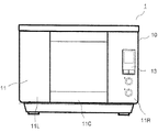
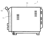
以下に本発明の実施形態を図面を参照して説明する。図1、図2は一実施形態の蒸気調理器を示す正面図及び側面図である。蒸気調理器1は過熱蒸気によって被加熱物を調理する。蒸気調理器1は直方体形状のキャビネット10を備えている。キャビネット10の正面には扉11が設けられる。
Embodiments of the present invention will be described below with reference to the drawings. 1 and 2 are a front view and a side view showing a steam cooker according to an embodiment. The
扉11は下端を中心に垂直面内で回動可能に枢支され、上部には扉11を開閉するためのハンドル12が設けられている。扉11の中央部11Cには耐熱ガラスをはめ込んで内部を視認できる透過部11a(図3参照)が設けられる。中央部11Cの左右には金属製装飾板を表面に設けた左側部11L及び右側部11Rが対称的に配置されている。扉11の右側部11Rには操作パネル13が設けられている。
The
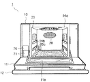
図3は扉11を開いた状態の蒸気調理器1の正面図を示している。扉11はハンドル12を把持して手前に引くと回動し、垂直な閉鎖状態から水平な開放状態へと90゜姿勢を変えることができる。扉11を開くとキャビネット10の正面が露出する。
FIG. 3 shows a front view of the
扉11の中央部11Cに対応する箇所には加熱室20が設けられる。扉11の左側部11Lに対応する箇所には水タンク室70が設けられ、蒸気発生用の水を貯溜する水タンク71が収納される。扉11の右側部11Rに対応する箇所には特に開口部は設けられていないが、内部に制御基板(不図示)が配置されている。
A
加熱室20は略直方体に形成され、扉11に面した正面側の全面が被加熱物F(図5参照)を出し入れするための開口部20dになっている。扉11の回動により開口部20dが開閉される。加熱室20の壁面はステンレス鋼板で形成され、加熱室20の外周面には断熱対策が施されている。
The
図4は加熱室20内の詳細を示す正面図である。加熱室20の側壁には複数の受皿支持部20b、20cが異なる高さに設けられる。上段の受皿支持部20bは反射部68よりも下方に設けられる。受皿支持部20b、20cの一方または両方にはステンレス鋼板製の受皿21が係止される。受皿21上には被加熱物F(図5参照)を載置するステンレス鋼線製のラック22が設置される。
FIG. 4 is a front view showing details in the
過熱蒸気により調理を行う場合は、上段の受皿支持部20bに受皿21が設置される。これにより、後述するように反射部68の反射によって被加熱物Fの下面に過熱蒸気を導くことができる。上段及び下段の受皿支持部20b、20cに受皿21を設置してもよい。これにより、一度に多くの被加熱物Fを調理することができる。
When cooking with superheated steam, the
この時、受皿支持部20bに配される受皿21は通気性を有するように形成され、下段の受皿21上の被加熱部の上面に過熱蒸気が供給される。また、下段の受皿21上の被加熱部の下面は加熱室20の底面に配された加熱ヒータ101(図5参照)により加熱される。
At this time, the
加熱室20の奥側の背壁には左右方向の略中央部に吸気口28が設けられ、左方下部に排気口32aが設けられる。反射部68は加熱室20の両側壁に凹設され、表面が曲面により形成されている。後述する噴出カバー61から反射部68に向けて側方に噴き出された過熱蒸気は反射部68で反射して被加熱物Fの下方に導かれるようになっている。
The back wall on the back side of the
加熱室20の天面には、過熱蒸気を噴き出すステンレス鋼板から成る噴出カバー61が取り付けられる。噴出カバー61の右側部の手前側には加熱室20内を照明する照明装置69が設けられる。
An ejection cover 61 made of a stainless steel plate that ejects superheated steam is attached to the top surface of the
噴出カバー61は平面視が矩形に対して前部の両コーナーが面取りされた略六角形に形成されている。噴出カバー61は上下両面とも塗装等の表面処理によって暗色に仕上げられている。これにより、蒸気加熱ヒータ41(図5参照)の輻射熱を吸収して噴出カバー61の下面から加熱室20に輻射される。
The
噴出カバー61の底面及び周面には複数の噴気口65、66(図5参照)が設けられる。各噴気口65、66の周縁は筒状に形成され、噴気口65、66の軸方向に気流を案内することができる。
A plurality of
図5は蒸気調理器1の内部の概略構造を示している。同図において、加熱室20は側面から見た図になっている。水タンク71は前述の図3に示すように加熱室20の左方に配され、ジョイント部58を介してタンク水位検出容器91と連通する。これにより、キャビネット10(図2参照)に対して水タンク71が着脱自在になっている。
FIG. 5 shows a schematic structure inside the
タンク水位検出容器91には水位センサ56が設けられる。水位センサ56は複数の電極を有し、電極間の導通により水位を検知する。本実施形態ではGND電極と3本の検知電極によって水位を3段階に検知している。水位センサ56の検知によって水タンク71の水位が所定水位よりも低下すると、給水を促すように報知される。
The tank water
タンク水位検出容器91には給水路55が底部まで延びて浸漬される。給水路55は経路途中に給水ポンプ57が設けられ、蒸気発生装置50に接続される。蒸気発生装置50は軸方向が垂直な筒型のポット51を有し、給水ポンプ57の駆動によって水タンク71からポット51に給水される。
In the tank water
ポット51は金属、合成樹脂、セラミック或いはこれらの異種材料の組み合わせ等により筒型に形成され、耐熱性を有している。ポット51内には螺旋状のシーズヒータから成る蒸気発生ヒータ52が浸漬される。蒸気発生ヒータ52の通電によってポット51内の水が昇温され、蒸気が発生する。
The
ポット51内には上面から螺旋状の蒸気発生ヒータ52内に延びた筒状の隔離壁51aが設けられる。隔離壁51aにより蒸気発生ヒータ52と隔離される水位検知室51bが形成される。隔離壁51aはポット51の底面に対して隙間を有するように形成され、水位検知室51bの内部と外部とが連通して同じ水位に維持される。
A
水位検知室51b内にはポット51内の水位を検知するポット水位検知部81が設けられる。ポット水位検知部81は複数の電極を有し、電極間の導通によりポット51内の水位を検知する。蒸気発生ヒータ52と水位検知室51bとが隔離壁51aで隔離されるため、蒸気発生ヒータ52に接した水の沸騰による発泡がポット水位検知部81に伝えられにい。これにより、発泡による電極の導通を回避し、ポット水位検知部81の検知精度を向上することができる。
A pot
尚、ポット51の外周面にヒータ等を密着してポット51内の水を昇温してもよい。この時、ポット51の周壁はポット51内の水を加熱する加熱手段を構成し、水位検知室51bはポット51の周壁に対して隔離して設けられる。また、蒸気発生ヒータ52をIHヒータにより形成してもよい。
Note that the temperature of the water in the
ポット51の上面には後述する循環ダクト35に接続した蒸気供給ダクト34が導出される。ポット51の周面の上部にはタンク水位検出容器91に連結される溢水パイプ98が設けられる。これにより、ポット51の溢水が水タンク71に導かれる。溢水パイプ98の溢水レベルはポット51内の通常の水位レベルよりも高く、蒸気供給ダクト34よりも低い高さに設定されている。
A
ポット51の下端には排水パイプ53が導出される。排水パイプ53の経路途中には排水バルブ54が設けられている。排水パイプ53は水タンク71内に設けた排水貯溜部71aに向かって所定角度の勾配を有している。これにより、排水バルブ54を開いてポット51内の水を排水貯溜部71aに排水して貯溜し、水タンク71を取り外して廃棄することができる。
A
加熱室20の外壁には背面から上面に亙って循環ダクト35が設けられる。循環ダクト35は加熱室20の背壁に形成された吸気口28を開口し、加熱室20の上方に配された蒸気昇温装置40に接続される。蒸気昇温装置40の下面は噴出カバー61で覆われ、上面は上カバー47で覆われる。
A
循環ダクト35内には遠心ファンから成る送風ファン26が設置され、蒸気供給ダクト34は送風ファン26の上流側に接続される。送風ファン26の駆動によって蒸気発生装置50により発生した蒸気は蒸気供給ダクト34を介して循環ダクト35に流入する。また、加熱室20内の蒸気は吸気口28から吸引され、循環ダクト35を通って噴出カバー61の噴気口65、66から噴き出されて循環する。蒸気の噴出しと吸引とを共通の送風ファン26により行うので、蒸気調理器1のコスト増加を抑制することができる。
A
尚、通常の場合加熱室20内の気体は空気であるが、蒸気調理を始めると空気が蒸気で置き換えられる。以下の説明において、加熱室20内の気体が蒸気に置き換わっているものとする。
In general, the gas in the
循環ダクト35の上部には電動式のダンパ48を介して分岐する排気ダクト33が設けられる。排気ダクト33は外部に臨む開放端を有し、ダンパ48を開いて送風ファン26を駆動することにより加熱室20内の蒸気を強制排気する。また、加熱室20の下部には排気口32aを介して連通する排気ダクト32が導出される。排気ダクト32はステンレス鋼等の金属から成り、外部に臨む開放端を有して加熱室20内の蒸気を自然排気する。
An
蒸気昇温装置40はシーズヒータから成る蒸気加熱ヒータ41を備え、蒸気発生装置50で発生した蒸気を更に加熱して過熱蒸気を生成する。蒸気昇温装置40は平面的に見て加熱室20の天井部の中央部に配置される。また、加熱室20の天面に対して面積が狭く、小さい容積に形成して高い加熱効率が得られるようになっている。
The steam
加熱室20の側方の下部には加熱室20の底面20aに溜まる結露水を排水する排水部110が設けられる。排水部110は排水トレイ114、配管111、113及びチューブポンプ120を備えている。排水トレイ114は扉11の下方に着脱自在に配され、排水部110で搬送された結露水を貯溜する。また、扉11の内面に付着した結露水が扉11を開いた際に流下して排水トレイ114に貯留されるようになっている。
A
配管111は加熱室20の側壁に突設して屈曲した樹脂製のパイプから成る(解りやすくするため図5では背壁に描いている)。配管111の先端は加熱室20の底面20aと隙間を介して離れ、下向きに開口した排水孔111aを形成する。排水孔111aには網状のフィルター(不図示)が設けられている。配管113は樹脂製のパイプから成り、排水トレイ114に対向して開口する。配管111、113の間はシリコンゴム等から成る可撓性のチューブ112により連結される。
The
チューブポンプ120は有底筒状のハウジング123内に回転板124が設けられ、回転板124の周部に複数のローラー125が突設される。チューブ112はハウジング123の内周壁に沿って環状に配される。ハウジング123とローラー125との間はチューブ112の外径よりも狭く形成され、チューブ112がローラー125により押圧される。
In the
チューブポンプ120の駆動によって回転板124が矢印Aの方向に回転すると、チューブ112の長手方向に沿ってローラー125が回転しながらチューブ112を順次押圧する。これにより、チューブ112内の流体が一方向に順次押し出されて搬送され、逆方向の流体の流通が阻止される。
When the
加熱室20の底面20aに溜まる結露水は排水孔111aから吸引され、排水トレイ114に搬送される。排水トレイ114に溜まった水は排水トレイ114を脱着して廃棄される。これにより、加熱室20内の気密性を保持して排水を行うことができる。尚、チューブポンプ120により結露水を水タンク71の排水貯溜部71aに搬送してもよい。
Condensed water collected on the
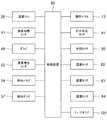
図6は蒸気調理器1の制御構成を示すブロック図である。蒸気調理器1はマイクロプロセッサ、不揮発性のメモリおよびタイマを有した制御装置80を備えている。制御装置80には送風ファン26、蒸気加熱ヒータ41、ダンパ48、蒸気発生ヒータ52、排水バルブ54、給水ポンプ57、操作パネル13、ポット水位検知部81、タンク水位検知部56、温度センサ82、83、湿度センサ84、チューブポンプ120が接続される。制御装置80によって所定のプログラムに従って各部を制御して、蒸気調理器1が駆動される。
FIG. 6 is a block diagram showing a control configuration of the
操作パネル13は表示部(不図示)を有し、制御状況を表示部に表示する。また、操作パネル13に配置した各種操作キーを通じて動作指令の入力を行う。操作パネル13には各種の音を出す音発生装置(不図示)も設けられている。温度センサ82は加熱室20内の温度を検知する。温度センサ83はポット51内の水温を検知する。湿度センサ84は加熱室20内の湿度を検知する。制御装置80のメモリには被加熱物に応じた調理シーケンスや加熱室20の温度等に応じて調理シーケンスを補正する補正データ等が格納される。
The
また、制御装置80の制御によって電源(不図示)から蒸気加熱ヒータ41及び蒸気発生ヒータ52に供給される。この時、蒸気加熱ヒータ41及び蒸気発生ヒータ52の供給電力はデューティ比によって配分される。即ち、蒸気加熱ヒータ41がオンになると蒸気発生ヒータ52がオフになり、蒸気加熱ヒータ41がオフになると蒸気発生ヒータ52がオンになるように切り替えられる。これにより、蒸気加熱ヒータ41及び蒸気発生ヒータ52の供給電力の一方のデューティ比が大きくなると、他方のデューティ比が小さくなる。
Further, it is supplied from a power source (not shown) to the
上記構成の蒸気調理器1において、扉11を開けて水タンク71を水タンク室70から引き出して、水タンク71内に水が入れられる。満水状態にした水タンク71は水タンク室70に押し込まれ、ジョイント部58によりタンク水位検出容器91に連結される。被加熱物Fをラック22上に載置して扉11を閉じ、操作パネル13を操作して調理メニューが選択される。そして、スタートキー(不図示)を押下することにより調理メニューに対応した調理シーケンスが開始する。
In the
図7は調理シーケンスの動作を示すフローチャートである。調理シーケンスは第1、第2調理工程を有している。第1調理工程では蒸気発生ヒータ52の供給電力(例えば、1000W)が蒸気加熱ヒータ41の供給電力(例えば、300W)よりも大きくなっている。第2調理工程では蒸気発生ヒータ52が停止される。
FIG. 7 is a flowchart showing the operation of the cooking sequence. The cooking sequence has first and second cooking steps. In the first cooking step, the supply power (for example, 1000 W) of the
調理シーケンスが開始されると、ステップ#11で送風ファン26が駆動される。送風ファン26の駆動により吸気口28から加熱室20内の蒸気が循環ダクト35に吸い込まれる。この時、ダンパ48は閉じられており、加熱室20内の空気が循環される。ステップ#12では給水ポンプ57が運転を開始して蒸気発生装置50に給水される。この時、排水バルブ54は閉じられている。
When the cooking sequence is started, the
給水ポンプ57の駆動により給水路55を介してポット51内に給水され、ポット51が所定の水位になるとポット水位検知部81の検知によって給水が停止される。この時、タンク水位検知部56により水タンク71の水位が監視され、水タンク71に調理に必要十分な水がない場合は警告が報知される。
When the
ステップ#13では加熱室20の温度が温度センサ82により検知される。送風ファン26を駆動して加熱室20の空気を循環した後に温度を検知することにより加熱室20の温度を正確に検知することができる。ステップ#14ではポット51の水温が温度センサ83により検知される。
In
ステップ#15では加熱室20が所定の温度(例えば、50℃)よりも高温か否かが判断される。加熱室20が所定の温度よりも低温の場合はステップ#18に移行する。加熱室20が所定の温度よりも高温の場合はステップ#16で第2調理工程の時間を短縮するように調理シーケンスが補正される。即ち、調理開始時の加熱室20が高温の時に低温の時よりも第2調理工程の時間が短縮される。
In
ステップ#17では第1調理工程の蒸気発生ヒータ52及び蒸気加熱ヒータ41の供給電力を可変するように調理シーケンスが補正される。即ち、調理開始時の加熱室20が高温の時に低温の時よりも第1調理工程の蒸気発生ヒータ52の供給電力を大きくする(例えば、1100W)。また、蒸気加熱ヒータ41の供給電力を小さくする(例えば、200W)。蒸気発生ヒータ52の供給電力はオン時間を増やすことにより大きくすることができる。蒸気加熱ヒータ41の供給電力はオン時間を減らすことにより小さくすることができる。
In step # 17, the cooking sequence is corrected so as to vary the power supplied to the
ステップ#18ではステップ#14で検知したポット51の水温が所定の温度(例えば、70℃)よりも高温か否かが判断される。ポット51の水温が所定の温度よりも低温の場合はステップ#21に移行する。ポット51の水温が所定の温度よりも高温の場合はステップ#19で第1調理工程の時間を短縮するように調理シーケンスが補正される。即ち、調理開始時のポット51の水温が高温の時に低温の時よりも第1調理工程の時間が短縮される。以上により、調理シーケンスが決定される。
In
ステップ#21では蒸気発生ヒータ52に通電され、蒸気発生ヒータ52はポット51内の水を直接加熱する。ステップ#22では蒸気加熱ヒータ41に通電される。ポット51内の水が所定温度に到達した後に蒸気加熱ヒータ41に通電してもよい。
In
ポット51内の水が沸騰すると100℃且つ1気圧の飽和蒸気が発生し、飽和蒸気が蒸気供給ダクト34を介して循環ダクト35に流入する。送風ファン26から圧送された蒸気は循環ダクト35を流通して蒸気昇温装置40に流入する。
When the water in the
蒸気昇温装置40に流入した蒸気は蒸気加熱ヒータ41により熱せられて100℃以上の過熱蒸気となる。通常、150℃から300℃にまで昇温した過熱蒸気が使用される。また、蒸気発生ヒータ52の供給電力が蒸気加熱ヒータ41の供給電力よりも大きいため、大量の過熱蒸気が加熱室20に供給されて第1調理工程が行われる。
The steam that has flowed into the steam
過熱蒸気の一部は噴気孔65から真下方向(矢印B)に噴き出される。これにより、被加熱物Fの上面が過熱蒸気と接触する。また、過熱蒸気の一部は噴気口66から側方の斜め下方向に向けて噴き出される。側方に噴き出された過熱蒸気は反射部68で反射し、被加熱物Fの下方に導かれる。これにより、被加熱物Fの下面が過熱蒸気と接触する。
A part of the superheated steam is ejected from the
被加熱物Fの表面が100℃以下の場合は、過熱蒸気が被加熱物Fの表面で凝縮する。この凝縮熱(潜熱)は、539cal/gと大きいため、対流伝熱に加えて被加熱物Fに大量の熱を与えることができる。これにより、被加熱物Fは内部温度が急激に上昇する。 When the surface of the object to be heated F is 100 ° C. or less, the superheated steam is condensed on the surface of the object to be heated F. Since this condensation heat (latent heat) is as large as 539 cal / g, in addition to the convection heat transfer, a large amount of heat can be given to the heated object F. As a result, the internal temperature of the article to be heated F rises rapidly.
時間の経過に伴って加熱室20内の蒸気量が増加すると、余剰となった蒸気は排気ダクト32を通じて外部に放出される。
When the amount of steam in the
噴気口65、66から噴き出された過熱蒸気は被加熱物Fに熱を与えた後、吸気口28から循環ダクト35内に吸引され、蒸気昇温装置40に流入する。これにより、加熱室20内の蒸気は循環を繰り返して調理が行われる。
The superheated steam ejected from the
ステップ#23では第1調理工程の調理時間が経過するまで待機し、第1調理工程の調理時間が経過するとステップ#24に移行する。第1調理工程の調理時間は被加熱物Fの種類に応じた油脂溶融温度特性に基づいて決められる。肉類等の被加熱物Fは約30〜60℃の油脂溶融温度帯を超えると、内部に含まれる油脂が溶融して滲み出しが開始される。
In
各食品によって油脂溶融温度特性が異なり、例えば、豚肉の油脂溶融温度帯は約33〜46℃、牛肉の油脂溶融温度帯は約40〜50℃である。制御装置80に設けられるメモリには各食品に応じた油脂溶融温度帯を超えるまでの時間が記憶され、油脂溶融温度帯を超えると第1調理工程が終了して第2調理工程に移行する。
The fat and oil melting temperature characteristic differs depending on each food. For example, the fat and oil melting temperature zone of pork is about 33 to 46 ° C, and the fat and oil melting temperature zone of beef is about 40 to 50 ° C. The memory provided in the
ステップ#24では蒸気発生ヒータ52が停止される。ステップ#25では蒸気加熱ヒータ41に最大電力(例えば、1300W)が供給される。これにより、第2調理工程に移行する。第2調理工程では被加熱物Fは主に表面が加熱され、油脂溶融温度帯を超えた所望の内部温度(例えば、70〜80℃)に維持されるとともに表面に焼き色が付けられる。この時、蒸気発生ヒータ52に蒸気加熱ヒータ41よりも小さい電力を供給してもよい。
In
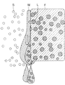
図8に示すように、被加熱物Fは油脂溶融温度帯よりも高温に維持されると油脂Lが溶融し、被加熱物Fの収縮によって油脂Lが表面に溶け出す。蒸気Sが被加熱物Fの表面で凝縮した凝縮水Wは油脂Lを取り込んで流下する。これにより、被加熱物Fが脱油される。 As shown in FIG. 8, when the object to be heated F is maintained at a temperature higher than the oil / fat melting temperature zone, the oil / fat L is melted, and the oil / fat L is melted on the surface by contraction of the object to be heated F. The condensed water W in which the steam S is condensed on the surface of the article to be heated F takes in the oil L and flows down. Thereby, the to-be-heated material F is deoiled.
ステップ#26では第2調理工程の調理時間が経過するまで待機する。第2調理工程の調理時間が経過すると被加熱物Fが所望の表面状態になり、調理が終了する。そして、制御装置80によって操作パネル13の表示部に調理の終了を表示するとともに合図音が報知される。調理終了を知らされた使用者によって扉11が開かれると、ダンパ48が開いて加熱室20内の蒸気が排気ダクト33から急速に強制排気される。これにより、使用者は高温の蒸気に触れずに、安全に加熱室20内から被加熱物Fを取り出すことができる。
In
本実施形態によると、蒸気発生ヒータ52の供給電力を蒸気加熱ヒータ41の供給電力よりも大きく過熱蒸気により被加熱物Fを調理する第1調理工程を有するので、大量の過熱蒸気の潜熱によって肉類等の被加熱物Fの内部温度を急速に上昇させることができる。これにより、早期に被加熱物Fの内部温度を油脂溶融温度帯よりも高温にして脱油を充分行うことができる。
According to the present embodiment, since the supply power of the
また、第1調理工程から蒸気発生ヒータ52を停止して蒸気加熱ヒータ41に最大電力を供給した第2調理工程に切り替えるので、被加熱物Fを所望の内部温度に維持するとともに表面に焼き色を付けて調理を完了させることができる。この時、調理開始時の加熱室20が高温の時に第2調理工程の時間を短縮したので、被加熱物F表面の焦げを防止して調理の仕上り状態を向上することができる。更に、調理時間を短縮することができる。また、第1調理工程で充分な調理時間を確保して大量の蒸気によって脱油効果を低下させない。
Further, since the
尚、第2調理工程で蒸気加熱ヒータ41よりも小さい電力を蒸気発生ヒータ52に供給しても同様の効果を得ることができる。特に、蒸気発生ヒータ52を停止すると、省電力化を図ることができる。また、蒸気加熱ヒータ41に最大電力を供給可能となり、この場合は第2調理工程をより短縮することができる。
In addition, the same effect can be acquired even if electric power smaller than the
また、調理開始時のポット51の水温が高温の時は蒸気の供給が早期に開始される。このため、第1調理工程の時間を短縮しても被加熱物Fの内部温度を充分上昇させることができるとともに脱油効果を低下させない。このため、第1調理工程の時間を短縮することにより、良好な仕上り状態が得られるとともに調理時間をより短縮することができる。
Further, when the water temperature of the
また、調理開始時の加熱室20が高温の時に第1調理工程の蒸気加熱ヒータ41の供給電力を小さくしても被加熱物に充分焼き色を付けることができる。このため、蒸気加熱ヒータ41の供給電力を小さくし、その分だけ蒸気発生ヒータ52の供給電力を大きくして蒸気量を増やすことができる。これにより、第1調理工程を短縮して、調理時間をより短縮することができる。
Moreover, even if the power supplied to the
次に第2実施形態について説明する。本実施形態は第1実施形態の蒸気調理器と同様に構成され、調理シーケンスの動作が異なる。図9は本実施形態の蒸気調理器1の調理シーケンスの動作を示すフローチャートである。前述の図7とステップ#11〜#14及びステップ#23〜#26の動作は同様であるので説明を省略する。
Next, a second embodiment will be described. This embodiment is configured similarly to the steam cooker of the first embodiment, and the operation of the cooking sequence is different. FIG. 9 is a flowchart showing the operation of the cooking sequence of the
ステップ#15では加熱室20が所定の温度(例えば、50℃)よりも高温か否かが判断される。加熱室20が所定の温度よりも低温の場合はステップ#21に移行する。加熱室20が所定の温度よりも高温の場合はステップ#20で第2調理工程の蒸気加熱ヒータ41の供給電力を小さくするように調理シーケンスが補正される。蒸気加熱ヒータ41の供給電力はオン時間を減らすことにより小さくすることができる。これにより、調理開始時の加熱室20が高温の時に低温の時よりも第2調理工程の加熱温度が下げられる。
In
そして、第1調理工程が行われ、第1調理工程が終了すると第2調理工程が行われる。この時、ステップ#25で蒸気加熱ヒータ41の供給電力は第1調理工程よりも増加される。即ち、調理開始時の加熱室20が低温の場合は最大電力(例えば、1300W)が供給される。また、調理開始時の加熱室20が高温の場合は最大電力よりも低い電力(例えば、1000W)が供給される。
Then, the first cooking process is performed, and when the first cooking process is completed, the second cooking process is performed. At this time, the power supplied to the
本実施形態によると、第1実施形態と同様に、蒸気発生ヒータ52の供給電力を蒸気加熱ヒータ41の供給電力よりも大きく過熱蒸気により被加熱物Fを調理する第1調理工程を有するので、大量の過熱蒸気の潜熱によって肉類等の被加熱物Fの内部温度を急速に上昇させることができる。これにより、早期に被加熱物Fの内部温度を油脂溶融温度帯よりも高温にして脱油を充分行うことができる。
According to the present embodiment, as in the first embodiment, since the supply power of the
また、蒸気発生ヒータ52を停止して蒸気加熱ヒータ41に最大電力を供給した第2調理工程に切り替えるので、被加熱物Fを所望の内部温度に維持するとともに表面に焼き色を付けて調理を完了させることができる。この時、調理開始時の加熱室20が高温の時に第2調理工程の蒸気加熱ヒータの供給電力を下げたので、被加熱物F表面の焦げを防止して調理の仕上り状態を向上することができる。更に、第1実施形態よりも脱油時間を長くして脱油効果を向上することができる。
In addition, since the
第1、第2実施形態において、図7、図9のステップ#15で加熱室20が所定の温度よりも高温か否かを判断しているが、ステップ#15を省いてもよい。即ち、加熱室20の温度に対応して細分化された補正データをメモリに保持し、それぞれの温度に応じて調理シーケンスを補正してもよい。
In the first and second embodiments, it is determined in
同様に、図7のステップ#18でポット51の水温が所定の温度よりも高温か否かを判断しているが、ステップ#18を省いてもよい。即ち、ポット51の水温に対応して細分化された補正データをメモリに保持し、それぞれの温度に応じて調理シーケンスを補正してもよい。
Similarly, it is determined in
また、蒸気加熱ヒータ41を加熱室20の天井面に配しているが、加熱室20に連結されるダクト内に配してもよい。即ち、第2調理工程で熱風により被加熱物Fを加熱するコンベクション型にしてもよい。しかしながら、本実施形態のように蒸気加熱ヒータ41を加熱室20の天井面に配置すると、輻射熱によって被加熱物Fが加熱される。このため、被加熱物Fに容易に焼き色を付けることができ、調理時間をより短縮することができる。この時、送風ファン26を停止して蒸気の循環を停止してもよい。これにより、省電力化を図ることができる。
Further, although the
本発明は、加熱室内に蒸気を噴出して被加熱物の調理を行う家庭用や業務用の蒸気調理器に利用することができる。 INDUSTRIAL APPLICABILITY The present invention can be used for a household or business steam cooker that jets steam into a heating chamber to cook an object to be heated.
1 蒸気調理器
11 扉
20 加熱室
21 受皿
26 送風ファン
28 吸気口
31 排気ファン
32、33 排気ダクト
34 蒸気供給ダクト
35 循環ダクト
40 蒸気昇温装置
41 蒸気加熱ヒータ
48 ダンパ
50 蒸気発生装置
51 ポット
52 蒸気発生ヒータ
54 排水バルブ
55 給水路
56 タンク水位検知部
57 給水ポンプ
61 噴出カバー
65、66 噴気口
68 反射部
71 水タンク
71a 排水貯溜部
81 ポット水位検知部
91 タンク水位検出容器
101 加熱ヒータ
110 排水部
111、113 配管
111a 排水孔
112 チューブ
114 排水トレイ
120 チューブポンプ
121 モータ
122 流体搬送部
123 ハウジング
124 回転板
125 ローラー
F 被加熱物
L 油脂
S 蒸気
W 結露水
DESCRIPTION OF
Claims (6)
Priority Applications (1)
| Application Number | Priority Date | Filing Date | Title |
|---|---|---|---|
| JP2007230149A JP4987635B2 (en) | 2007-09-05 | 2007-09-05 | Steam cooker |
Applications Claiming Priority (1)
| Application Number | Priority Date | Filing Date | Title |
|---|---|---|---|
| JP2007230149A JP4987635B2 (en) | 2007-09-05 | 2007-09-05 | Steam cooker |
Related Child Applications (1)
| Application Number | Title | Priority Date | Filing Date |
|---|---|---|---|
| JP2012050514A Division JP2012107866A (en) | 2012-03-07 | 2012-03-07 | Steam cooker |
Publications (3)
| Publication Number | Publication Date |
|---|---|
| JP2009063197A JP2009063197A (en) | 2009-03-26 |
| JP2009063197A5 JP2009063197A5 (en) | 2009-12-03 |
| JP4987635B2 true JP4987635B2 (en) | 2012-07-25 |
Family
ID=40557929
Family Applications (1)
| Application Number | Title | Priority Date | Filing Date |
|---|---|---|---|
| JP2007230149A Active JP4987635B2 (en) | 2007-09-05 | 2007-09-05 | Steam cooker |
Country Status (1)
| Country | Link |
|---|---|
| JP (1) | JP4987635B2 (en) |
Families Citing this family (1)
| Publication number | Priority date | Publication date | Assignee | Title |
|---|---|---|---|---|
| KR102100427B1 (en) * | 2019-12-31 | 2020-04-13 | 조석호 | Fried food drying apparatus |
Family Cites Families (4)
| Publication number | Priority date | Publication date | Assignee | Title |
|---|---|---|---|---|
| JP4018586B2 (en) * | 2003-04-25 | 2007-12-05 | 松下電器産業株式会社 | Cooker |
| JP4589825B2 (en) * | 2005-06-23 | 2010-12-01 | 株式会社東芝 | Cooking equipment |
| JP2007032926A (en) * | 2005-07-27 | 2007-02-08 | Hitachi Appliances Inc | Cooker |
| JP4412331B2 (en) * | 2007-02-13 | 2010-02-10 | パナソニック株式会社 | Superheated steam cooker |
-
2007
- 2007-09-05 JP JP2007230149A patent/JP4987635B2/en active Active
Also Published As
| Publication number | Publication date |
|---|---|
| JP2009063197A (en) | 2009-03-26 |
Similar Documents
| Publication | Publication Date | Title |
|---|---|---|
| KR101232488B1 (en) | Steam cooker | |
| CN101535722B (en) | Device for diluting discharged vapor and cooker with the same | |
| CN100453012C (en) | Heating apparatus for cooking and method for controlling the same | |
| KR102133286B1 (en) | Electronic cooking device possible automatic cleaning of kitchen ctructure | |
| US7802564B2 (en) | Steam cooking apparatus | |
| JP6267309B2 (en) | Steam cooker | |
| JP2015105773A (en) | Water supply device and heating cooker | |
| JP5052988B2 (en) | Steam cooker | |
| JP5042739B2 (en) | Steam cooker | |
| JP6043414B2 (en) | Steam cooker | |
| JP4987635B2 (en) | Steam cooker | |
| JP5797729B2 (en) | Steam cooker | |
| JP2012107866A (en) | Steam cooker | |
| JP2009041818A (en) | Steam cooker | |
| JP5486648B2 (en) | Steam cooker | |
| JP4610530B2 (en) | Cooker | |
| JP2008067804A (en) | Grill device | |
| JP2011058677A (en) | Cooker | |
| JP2009036431A (en) | Steam cooker | |
| JP4615493B2 (en) | Cooker | |
| JP2008267668A (en) | Cooker | |
| JP2016003798A (en) | Heating cooker | |
| JP2009041820A (en) | Cooker | |
| JP2006038254A (en) | Cooker | |
| JP2006266613A (en) | Cooker |
Legal Events
| Date | Code | Title | Description |
|---|---|---|---|
| A521 | Written amendment |
Free format text: JAPANESE INTERMEDIATE CODE: A523 Effective date: 20091021 |
|
| A621 | Written request for application examination |
Free format text: JAPANESE INTERMEDIATE CODE: A621 Effective date: 20091021 |
|
| A131 | Notification of reasons for refusal |
Free format text: JAPANESE INTERMEDIATE CODE: A131 Effective date: 20120110 |
|
| A521 | Written amendment |
Free format text: JAPANESE INTERMEDIATE CODE: A523 Effective date: 20120307 |
|
| TRDD | Decision of grant or rejection written | ||
| A01 | Written decision to grant a patent or to grant a registration (utility model) |
Free format text: JAPANESE INTERMEDIATE CODE: A01 Effective date: 20120403 |
|
| A01 | Written decision to grant a patent or to grant a registration (utility model) |
Free format text: JAPANESE INTERMEDIATE CODE: A01 |
|
| A61 | First payment of annual fees (during grant procedure) |
Free format text: JAPANESE INTERMEDIATE CODE: A61 Effective date: 20120425 |
|
| R150 | Certificate of patent or registration of utility model |
Ref document number: 4987635 Country of ref document: JP Free format text: JAPANESE INTERMEDIATE CODE: R150 Free format text: JAPANESE INTERMEDIATE CODE: R150 |
|
| FPAY | Renewal fee payment (event date is renewal date of database) |
Free format text: PAYMENT UNTIL: 20150511 Year of fee payment: 3 |
|
| S531 | Written request for registration of change of domicile |
Free format text: JAPANESE INTERMEDIATE CODE: R313531 |
|
| R350 | Written notification of registration of transfer |
Free format text: JAPANESE INTERMEDIATE CODE: R350 |
|
| RD03 | Notification of appointment of power of attorney |
Free format text: JAPANESE INTERMEDIATE CODE: R3D03 |