JP5050552B2 - Method for manufacturing plasma display device - Google Patents
Method for manufacturing plasma display device Download PDFInfo
- Publication number
- JP5050552B2 JP5050552B2 JP2007033177A JP2007033177A JP5050552B2 JP 5050552 B2 JP5050552 B2 JP 5050552B2 JP 2007033177 A JP2007033177 A JP 2007033177A JP 2007033177 A JP2007033177 A JP 2007033177A JP 5050552 B2 JP5050552 B2 JP 5050552B2
- Authority
- JP
- Japan
- Prior art keywords
- chassis member
- panel
- plasma display
- sheet
- adhesive heat
- Prior art date
- Legal status (The legal status is an assumption and is not a legal conclusion. Google has not performed a legal analysis and makes no representation as to the accuracy of the status listed.)
- Expired - Fee Related
Links
Images


Landscapes
- Devices For Indicating Variable Information By Combining Individual Elements (AREA)
Description
本発明は、大画面で、薄型、軽量のディスプレイ装置として知られているプラズマディスプレイ装置の製造方法に関する。 The present invention relates to a method for manufacturing a plasma display device known as a thin, lightweight display device having a large screen.
近年、プラズマディスプレイ装置は、視認性に優れた大画面薄型表示デバイスとして注目されている。 In recent years, plasma display devices have attracted attention as large-screen thin display devices with excellent visibility.
プラズマディスプレイ装置は、気体放電で生じる真空紫外線で蛍光体層を励起させて画像を表示する表示デバイスであり、その基本構造は、画像を表示するプラズマディスプレイパネル(以下「パネル」と略記する)、パネルを駆動する回路ブロック等が取り付けられたシャーシ部材、およびパネルとシャーシ部材とを収容する筐体から成り立っている。 A plasma display device is a display device that displays an image by exciting a phosphor layer with vacuum ultraviolet rays generated by gas discharge, and its basic structure is a plasma display panel that displays an image (hereinafter abbreviated as “panel”), It comprises a chassis member to which a circuit block or the like for driving the panel is attached, and a housing for housing the panel and the chassis member.
パネルとシャーシ部材とはシート状の接着材を介して接着されており、シャーシ部材がボス部等により筐体に固定されることによってシャーシ部材に接着されたパネルを保持している。パネルとシャーシ部材との接着面積を十分に確保して接着する方法としては、パネルとシャーシ部材との間に接着材を介在させて重ね合わせるとともに、それらを押圧板で挟み、押圧板上から所定の圧力を加える方法が開示されている(例えば特許文献1参照)。 The panel and the chassis member are bonded via a sheet-like adhesive, and the chassis member is fixed to the housing by a boss portion or the like, thereby holding the panel bonded to the chassis member. As a method of bonding with securing a sufficient bonding area between the panel and the chassis member, an adhesive is interposed between the panel and the chassis member and they are overlapped. A method of applying a pressure of 2 is disclosed (for example, see Patent Document 1).
一方、廃棄時にはプラズマディスプレイ装置を分解する必要があるが、構成原料の再利用を考慮した場合、主として金属等を主原料とするシャーシ部材とガラス等を主原料とするパネルを剥離しなければならない。しかし、強固に接着されたシャーシ部材とパネルとを剥離するのは困難である。全面に亘って接着したパネルとシャーシ部材を分離するためには、例えばパネルを粉々にして、そのガラス片をきさげ等で少しずつシャーシ部材から除去すればよいが、この分離作業は非常に時間と手間がかかるものであった。 On the other hand, it is necessary to disassemble the plasma display device at the time of disposal. However, in consideration of the reuse of the constituent materials, the chassis member mainly made of metal or the like and the panel made mainly of glass or the like must be peeled off. . However, it is difficult to peel off the strongly bonded chassis member and the panel. In order to separate the panel and the chassis member bonded over the entire surface, for example, the panel may be shattered, and the glass piece may be removed from the chassis member little by little by scraping, but this separation work is very time consuming. It took time and effort.
そのため、パネルとシャーシ部材との分離を容易に行えるようにするために、周辺部に配置した延伸剥離式の接着材と、中央部に配置した非粘着性の放熱シートを備えたプラズマディスプレイ装置が提案されている(例えば特許文献2参照)。
上述した延伸剥離式の接着材は、感圧接着層を有し、押圧力を加えて硬化させることで接着し、また接着材を引っ張ることで接着力が大幅に減少して剥離するものである。しかしながら、このような延伸剥離式の接着材は、材料そのものが特殊であり高価であることに加えて、塗布装置や加熱装置を用いて接着するために、工程が煩雑になるという課題を有していた。 The above-described stretch-peelable adhesive has a pressure-sensitive adhesive layer, adheres by applying pressure to cure, and pulls the adhesive to significantly reduce the adhesive force and peel. . However, in addition to the material itself being special and expensive, such a stretch-peelable adhesive has a problem that the process becomes complicated because it is bonded using a coating device or a heating device. It was.
本発明は上記の課題を解決するものであり、パネルとシャーシ部材との接着強度を確保しつつ剥離も容易なプラズマディスプレイ装置の製造方法を提供することを目的とする。 The present invention solves the above-described problems, and an object of the present invention is to provide a method of manufacturing a plasma display device that can easily peel off while ensuring the adhesive strength between the panel and the chassis member.
上記目的を達成するために、本発明のプラズマディスプレイ装置の製造方法は、前面板と背面板とを対向配置して放電セルを形成したパネルと、パネルを保持するシャーシ部材とを備えたプラズマディスプレイ装置の製造方法であって、パネルとシャーシ部材との間に、背面板の中央部に非接着性放熱シートが配置されるとともに、背面板側の周辺部に接着性放熱シートが配置されるように、非接着性放熱シートと接着性放熱シートとを介在させ、その後、パネルとシャーシ部材とを押圧して接着する際に、接着性放熱シートを介在させた領域は非接着性放熱シートを介在させた領域よりも強く押圧し、接着性放熱シートを介在させた領域を押圧する部位の硬度が非接着性放熱シートを介在させた領域を押圧する部位の硬度よりも高い押圧板を用いることを特徴とする。この方法により、パネルとシャーシ部材との接着強度を確保しつつ剥離も容易なプラズマディスプレイ装置の製造方法を提供することが可能となる。 In order to achieve the above object, a method for manufacturing a plasma display device according to the present invention includes a panel having discharge cells formed by disposing a front plate and a back plate opposite to each other, and a chassis member holding the panel. A method for manufacturing an apparatus, wherein a non-adhesive heat radiating sheet is disposed in a central portion of a back plate between a panel and a chassis member, and an adhesive heat radiating sheet is disposed in a peripheral portion on the back plate side. The non-adhesive heat-dissipating sheet and the adhesive heat-dissipating sheet are interposed, and then the area where the adhesive heat-dissipating sheet is interposed when the panel and the chassis member are pressed and bonded to each other. strongly pressed than the region obtained by the adhesion hardness at a position for radiating sheet pressing area by interposing a non-adhesive radiator high pressure plate than the hardness of the portion the sheet to press the region is interposed Which comprises using. According to this method, it is possible to provide a method for manufacturing a plasma display device that ensures easy bonding between the panel and the chassis member and can be easily peeled off.
以上のように本発明によれば、パネルとシャーシ部材との接着強度を確保しつつ、剥離も容易なプラズマディスプレイ装置の製造方法を提供することができる。 As described above, according to the present invention, it is possible to provide a method of manufacturing a plasma display device that can easily peel off while ensuring the adhesive strength between the panel and the chassis member.
以下、本発明の一実施の形態によるプラズマディスプレイ装置の製造方法について、図面を参照しながら説明する。 Hereinafter, a method of manufacturing a plasma display device according to an embodiment of the present invention will be described with reference to the drawings.
(第1の実施の形態)
図1は、本発明の第1の実施の形態におけるパネルの構造を示す分解斜視図である。パネル30は、対向配置された前面板1と背面板2との間にマトリクス状に配置された複数の放電セル11を備え、前面板1および背面板2の周辺部をガラスフリット等の封着材(図示せず)によって封着された構造を有する。
(First embodiment)
FIG. 1 is an exploded perspective view showing the structure of the panel according to the first embodiment of the present invention. The
前面板1の前面基板10上には、走査電極14と維持電極15とからなる表示電極対16が平行に複数配列されている。そして表示電極対16は、誘電体層12および保護層13によって覆われている。
On the
他方、背面板2の背面基板20上には、表示電極対16に直交する方向に複数のアドレス電極21が互いに平行して配列されている。そしてアドレス電極21は、下地誘電体層22によって覆われている。また下地誘電体層22の上には、放電空間を区画し放電セル11を形成するための隔壁23が設けられている。さらに、下地誘電体層22上と隔壁23の側面部には蛍光体層24が形成されている。
On the other hand, on the
放電セル11には、放電ガスとして、例えばネオンやキセノン等が封入されている。そして、放電セル11内での放電により発生する紫外線によって蛍光体層24が励起されて可視光を発生し映像を表示する。
The
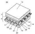
図2は、本発明の第1の実施の形態におけるプラズマディスプレイ装置40の内部構造を示す分解斜視図である。プラズマディスプレイ装置40は、パネル30を収容する筐体を構成する前面枠31およびバックカバー32と、前面枠31の開口部に配置されたガラス等からなる前面カバー33と、アルミニウム等からなる放熱板を兼ねたシャーシ部材34と、前面板1と背面板2からなるパネル30を駆動するための回路ブロック35と、パネル30とシャーシ部材34とを接着するための接着性放熱シート41とパネル30の放熱のための非接着性放熱シート42とが配置されている。
FIG. 2 is an exploded perspective view showing the internal structure of the
前面カバー33は、光学フィルターおよびパネル30の保護を兼ねるとともに、電磁波の不要輻射を抑制するために、例えば銀蒸着が施されている。バックカバー32には、パネル30等で発生した熱を外部に放出するための複数の通気孔32aが設けられている。
The
回路ブロック35は、シャーシ部材34の背面側に取り付けられ、パネル30の駆動とその制御を行うための電気回路を備えており、パネル30の縁部に引き出された電極引出部に、シャーシ部材34の四辺の縁部を越えて延びる複数のフレキシブル配線板(図示せず)によって電気的に接続されている。
The circuit block 35 is attached to the back side of the
また、シャーシ部材34の後面には、バックカバー32を固定するためのボス部34aがダイカスト等による一体成型により突設されている。なお、このシャーシ部材34は、アルミニウム平板に固定ピンを固定して構成してもよい。
Further, a
非接着性放熱シート42は、パネル30で発生した熱をシャーシ部材34に伝導するために、パネル30の背面板2側の中央部に配置されている。また非接着性放熱シート42は、粘着性の材料によって形成され、パネル30と背面板2とを粘着している。この粘着性の材料は、周囲から容易に剥がすことができる。それに対し接着性放熱シート41は、パネル30の背面板2側周辺部に配置され、パネル30とシャーシ部材34とを接着している。接着性放熱シート41はウレタン等の発泡海綿体にシリコンを含浸させた発泡体等などからなり、シート面と平行に切断することは可能だが、周辺からのシートの剥離に対しては強固な接着力を有する。したがって、中央部に非接着性放熱シート42を配置し、周辺部に接着性放熱シート41を配置することで、周辺からは容易に剥がれない構成となっている。
The non-adhesive
次に、シャーシ部材34とパネル30とを貼り付ける工程を説明する。図3は、本発明の第1の実施の形態におけるプラズマディスプレイ装置40の貼付け装置50を正面から見た概略図である。貼付け装置50は、四隅に垂設してある柱部材51、柱部材51で囲まれた箇所に形成された天部材52、シリンダーロッド53、シリンダーロッド53内に設置された油圧シリンダー54、油圧ユニット55、載置台56、パネル側押圧板57、昇降体58、昇降体58を案内するレール59、シャーシ部材側押圧板60、押圧板固定治具61を備えている。
Next, a process of attaching the
載置台56はステンレス等の剛性を有する金属からなり、上面は平滑に加工されている。載置台56上のパネル側押圧板57は圧縮弾性率の大きい弾性体からなり、表面が平滑なシート形状を有する。天部材52は柱部材51の上部に設置され、天部材52の上部は、油圧シリンダー54がシリンダーロッド53を下方に向けて天部材52を上下方向に貫通させて垂設してある。油圧シリンダー54の下面に設置された昇降体58は、柱部材51の内部に設けてあるレール59で案内されるようにしてあり、油圧シリンダー54によって上下方向に移動が可能である。油圧シリンダー54の制御は油圧ユニット55によって行われる。
The mounting table 56 is made of a metal having rigidity such as stainless steel, and the upper surface is processed smoothly. The panel-
シャーシ部材側押圧板60はパネル側押圧板57と同様の材質からなり、昇降体58の下部に設置され、昇降体58が下降することで、パネル側押圧板57との間で挟持物を挟み込んで押圧できる押圧機構を構成している。
The chassis member-
なお、シャーシ部材側押圧板60の設置は、シャーシ部材側押圧板60の周辺部を押圧板固定治具61で固定することによって行われており、着脱して別の押圧板に取り替えて押圧することができる。また、シャーシ部材側押圧板60を昇降体58へ固定せず、挟持物の上にシャーシ部材側押圧板60を設置した後に、シャーシ部材側押圧板60の上部から昇降体58で押圧することもできる。
The chassis member-
図4は、本発明の第1の実施の形態におけるプラズマディスプレイ装置40の製造工程を示す断面図である。図4(a)は、パネル30とシャーシ部材34とを載置台56上に設置する工程である。載置台56上に配置されたパネル側押圧板57上に、前面板1側を下に向けてパネル30を配置する。次にパネル30の背面板2上に、パネル周辺部には接着性放熱シート41、中央部には非接着性放熱シート42を配置し、その後にボス部34aを有するシャーシ部材34を配置する。
FIG. 4 is a cross-sectional view showing a manufacturing process of the
次に、図4(b)に示すようにシャーシ部材34の上に、昇降体58を下降させてシャーシ部材側押圧板60を配置する。なお、ここで用いるシャーシ部材側押圧板60は、図3で説明したものと同じであるが、シャーシ部材34上のボス部34a等の突起物に応じて適宜空孔部71を有している。この空孔部71は、シャーシ部材34への押圧による圧縮でみかけの板厚が薄くなった場合においても、シャーシ部材側押圧板60とシャーシ部材34とが接触しないような深さを有する。また、簡単化のために、図4における油圧シリンダー54、押圧板固定治具61の図示は省略している。
Next, as shown in FIG. 4B, the lifting
次に、図4(c)に示すように、昇降体58を降下させてシャーシ部材側押圧板60を押圧し、パネル30とシャーシ部材34を接着する。所定の時間を経過後、昇降体58を上方に上げる。
Next, as shown in FIG. 4C, the lifting
次に、図4(d)に示すように、昇降体58から押圧板固定治具61を解除してシャーシ部材側押圧板60の代わりにシャーシ部材側周辺部押圧板72を設置する。そして昇降体58を用いてパネル30とシャーシ部材34を接着する。シャーシ部材側周辺部押圧板72はシャーシ部材側押圧板60と同様の弾性体からなり、パネル30とシャーシ部材34の間に配置した接着性放熱シート41の上部とその周辺部のみが押圧できるような形状になっている。
Next, as shown in FIG. 4D, the pressing
以上の製造工程により、パネル周辺部において配置した接着性放熱シート41による接着が確実に行われる。また、パネル中央部に配置した非接着性放熱シート42によって、パネル30とシャーシ部材34とのいずれにも密着するため、パネル30で発生した熱を効率よくシャーシ部材34に伝導することができる。
By the above manufacturing process, the adhesion by the adhesive heat-dissipating
次に、このような構成にて接着されたシャーシ部材34とパネル30とを剥離する工程について説明する。図5は、本発明の第1の実施の形態におけるプラズマディスプレイ装置40の剥離工程を示す断面図である。図5(a)に、中央部においては非接着性放熱シート42が配置され、周辺部において接着性放熱シート41が配置されることによって接着されたパネル30とシャーシ部材34を示す。
Next, a process of peeling the
図5(b)は、接着性放熱シート41を切断する工程である。パネル30とシャーシ部材34の間隙へカッター73を挿入し、周辺部の接着性放熱シート41のみを四方から切断する。
FIG. 5B is a step of cutting the adhesive
図5(c)は、パネル30とシャーシ部材34との剥離工程である。中央部の非接着性放熱シート42は垂直剥離に対しては強固に保持されるが、周辺からの剥離は容易である。したがって、四辺の接着性放熱シート41をシート面に対して平行方向から切断し、分断することで、パネル30とシャーシ部材34とを剥離することができる。なお、非接着性放熱シート42は、パネル30に残るが、パネル30から非接着性放熱シート42の剥離は容易である。
FIG. 5C shows a peeling process between the
このように、本実施の形態における製造方法にてパネル30とシャーシ部材34とを接着したプラズマディスプレイ装置40は、移動時、使用時においては十分な接着強度でパネル30とシャーシ部材34が接着され、かつ分解時においては周辺部のみに配置された接着材をカッター等で切断するだけで簡単に剥離することができる。
As described above, in the
なお、本実施の形態では、パネル30の背面板2上に接着性放熱シート41、非接着性放熱シート42を配置し、その上にシャーシ部材34を設置し、シャーシ部材34側から押圧する形態の説明を行った。しかしながら本発明はこれに限定されるものではなく、例えば接着性放熱シート41および非接着性放熱シート42をシャーシ部材34側に予め配置しても構わない。
In the present embodiment, an adhesive
また、上下を逆にして、シャーシ部材側押圧板60とシャーシ部材34を配置し、シャーシ部材34の上に接着性放熱シート41、非接着性放熱シート42を配置し、その上にパネル30を載せ、さらにその上にパネル側押圧板57を載せて、パネル側押圧板57側から押圧してもよい。その場合は、図4(d)に示した再押圧工程は、シャーシ部材側押圧板60に代えてシャーシ部材側周辺部押圧板72を用いてパネル30側から行ってもよい。
Also, the chassis member-
(第2の実施の形態)
図6は、本発明の第2の実施の形態におけるプラズマディスプレイ装置40の製造工程を示す断面図である。図6(a)は図4(a)と同様であるが、簡単化のために、ボス部34aを省略している。
(Second Embodiment)
FIG. 6 is a sectional view showing a manufacturing process of the
図6(b)は、シャーシ部材34の上に、シャーシ部材側段差付き押圧板74を積層する工程を示している。図6(b)が図4(b)と異なるのは、シャーシ部材側押圧板60の代わりにシャーシ部材側段差付き押圧板74を用いているところである。シャーシ部材側段差付き押圧板74は、表面に段差75が設けられている。段差75はパネル30とシャーシ部材34の間に配置した接着性放熱シート41の上部に相当する部分で高くなっている。
FIG. 6B shows a step of laminating a
図6(c)は、シャーシ部材側段差付き押圧板74を押圧し、パネル30とシャーシ部材34を接着する工程を示している。本実施の形態においても、第1の実施の形態と同様に、シャーシ部材側段差付き押圧板74の上から昇降体58を用いて押圧力を加え、パネル30とシャーシ部材34を接着させる。シャーシ部材側段差付き押圧板74は、接着性放熱シート41の上部に相当する部分が高くなっているため、昇降体58によって均等な押圧を行っても接着性放熱シート41の上部に強い押圧力がかかり、非接着性放熱シート42の上部には弱い押圧力がかかる。したがって、接着性放熱シート41による接着をより確実に行うことができる。
FIG. 6C shows a process of pressing the chassis member side stepped
本実施の形態によれば、1回の押圧工程で、移動時、使用時においては十分な接着強度でパネル30とシャーシ部材34が接着される。また、分解時においては、周辺部のみに配置された接着材を、カッター等で切断するだけで、簡単に剥離できるプラズマディスプレイ装置40を製造することができる。
According to the present embodiment, the
(第3の実施の形態)
図7は、本発明の第3の実施の形態におけるプラズマディスプレイ装置40の製造工程を示す断面図である。図7(a)は、第2の実施の形態における図6(a)と同様であるので説明を省略する。
(Third embodiment)
FIG. 7 is a cross-sectional view showing a manufacturing process of the
図7(b)は、シャーシ部材34の上に、シャーシ部材側硬度差付き押圧板76を積層する工程を示している。図7(b)が図6(b)と異なるのは、シャーシ部材側段差付き押圧板74の代わりにシャーシ部材側硬度差付き押圧板76を用いているところである。シャーシ部材側硬度差付き押圧板76のシャーシ部材34に接する面は、パネル30とシャーシ部材34の間に配置した接着性放熱シート41の上部に相当する部分が、他の部分と比較して硬度が高くなっている。
FIG. 7B shows a step of laminating the chassis member-side hardness
図7(c)は、シャーシ部材側硬度差付き押圧板76を押圧し、パネル30とシャーシ部材34を接着する工程を示している。本実施の形態においても、第1の実施の形態と同様に、シャーシ部材側硬度差付き押圧板76の上から、昇降体58を用いて押圧力を加え、パネル30とシャーシ部材34を接着させる。シャーシ部材側硬度差付き押圧板76は、接着性放熱シート41の上部に相当する部分の硬度が高くなっているため、昇降体58によって均等な押圧を行っても接着性放熱シート41の上部に強い押圧力がかかり、非接着性放熱シート42の上部には弱い押圧力がかかる。したがって、接着性放熱シート41による接着をより確実に行うことができる。
FIG. 7C shows a step of pressing the chassis member-side hardness
本実施の形態によれば、1回の押圧工程で、移動時、使用時においては十分な接着強度でパネル30とシャーシ部材34が接着される。また、分解時においては、周辺部のみに配置された接着材を、カッター等で切断するだけで、簡単に剥離できるプラズマディスプレイ装置40を製造することができる。
According to the present embodiment, the
(第4の実施の形態)
図8は、本発明の第4の実施の形態におけるプラズマディスプレイ装置40の製造工程を示す断面図である。図8(a)は、図6(a)と同様であるので説明を省略する。
(Fourth embodiment)
FIG. 8 is a cross-sectional view showing a manufacturing process of the
図8(b)は、弾性体からなる2つの押圧板で挟む工程を示している。シャーシ部材34の上に、シャーシ部材側押圧板60を配置し、昇降体58を下降させる。昇降体58には接着性放熱シート41の上方に相当する場所に突起77が設けてある。
FIG. 8B shows a step of sandwiching between two pressing plates made of an elastic body. The chassis member
図8(c)は、シャーシ部材側押圧板60を押圧し、パネル30とシャーシ部材34を接着する工程を示している。本実施の形態においても、第1の実施の形態と同様に、シャーシ部材側押圧板60の上から、昇降体58を用いて押圧力を加え、パネル30とシャーシ部材34を接着させる。昇降体58は、接着性放熱シート41の上方に相当する場所の突起77により、周辺部位の押圧が強くなるため、昇降体58によって均等な押圧を行っても接着性放熱シート41の上部に強い押圧力がかかり、非接着性放熱シート42の上部には弱い押圧力がかかる。したがって、接着性放熱シート41による接着をより確実に行うことができる。
FIG. 8C shows a process of pressing the chassis member
このような製造装置にて接着したパネル30とシャーシ部材34を用いたプラズマディスプレイ装置40は、移動時、使用時においては十分な接着強度でパネル30とシャーシ部材34が接着され、かつ分解時においては、周辺部のみに配置された接着材を、カッター等で切断するだけで、簡単に剥離することができる。
In the
また、突起77を用いて押圧力を調整することを説明したが、中央部と周辺部とに押圧差を生じる手段を有すれば、上記方法に限定されるものではない。上記方法以外では、例えば中央部と周辺部とで独立に制御された昇降体58を用いる方法等でも同様の効果を有する。
In addition, the adjustment of the pressing force using the
本発明によれば、パネルとシャーシ部材との接着強度を確保しつつ、剥離も容易なプラズマディスプレイ装置の製造が可能になる。 ADVANTAGE OF THE INVENTION According to this invention, manufacture of the plasma display apparatus which is easy to peel is attained, ensuring the adhesive strength of a panel and a chassis member.
1 前面板
2 背面板
11 放電セル
30 パネル
34 シャーシ部材
40 プラズマディスプレイ装置
41 接着性放熱シート
42 非接着性放熱シート
57 パネル側押圧板
60 シャーシ部材側押圧板
72 シャーシ部材側周辺部押圧板
74 シャーシ部材側段差付き押圧板
76 シャーシ部材側硬度差付き押圧板
DESCRIPTION OF
Claims (1)
前記プラズマディスプレイパネルを保持するシャーシ部材とを備えたプラズマディスプレイ装置の製造方法であって、
前記プラズマディスプレイパネルと前記シャーシ部材との間に、前記背面板の中央部に非接着性放熱シートが配置されるとともに、前記背面板側の周辺部に接着性放熱シートが配置されるように、非接着性放熱シートと接着性放熱シートとを介在させ、その後、
前記プラズマディスプレイパネルと前記シャーシ部材とを押圧して接着する際に、
前記接着性放熱シートを介在させた領域は前記非接着性放熱シートを介在させた領域よりも強く押圧し、前記接着性放熱シートを介在させた領域を押圧する部位の硬度が前記非接着性放熱シートを介在させた領域を押圧する部位の硬度よりも高い押圧板を用いることを特徴とするプラズマディスプレイ装置の製造方法。 A plasma display panel in which a discharge cell is formed by disposing a front plate and a back plate opposite to each other;
A plasma display device manufacturing method comprising a chassis member for holding the plasma display panel,
Wherein between the plasma display panel and the chassis member, with non-adhesive heat radiation sheet on a central portion of the back plate is arranged, as adhesive radiating sheet is arranged on the periphery of the rear plate side, the a non-adhesive heat radiation sheet and adhesive heat radiation sheet is interposed, then,
When pressing and bonding the plasma display panel and the chassis member ,
The region where the adhesive heat-dissipating sheet is interposed is pressed more strongly than the region where the non-adhesive heat-dissipating sheet is interposed, and the hardness of the portion pressing the region where the adhesive heat-dissipating sheet is interposed is the non-adhesive heat dissipation. A method of manufacturing a plasma display device, comprising using a pressing plate having a hardness higher than that of a portion that presses a region where a sheet is interposed .
Priority Applications (1)
| Application Number | Priority Date | Filing Date | Title |
|---|---|---|---|
| JP2007033177A JP5050552B2 (en) | 2007-02-14 | 2007-02-14 | Method for manufacturing plasma display device |
Applications Claiming Priority (1)
| Application Number | Priority Date | Filing Date | Title |
|---|---|---|---|
| JP2007033177A JP5050552B2 (en) | 2007-02-14 | 2007-02-14 | Method for manufacturing plasma display device |
Publications (2)
| Publication Number | Publication Date |
|---|---|
| JP2008197428A JP2008197428A (en) | 2008-08-28 |
| JP5050552B2 true JP5050552B2 (en) | 2012-10-17 |
Family
ID=39756423
Family Applications (1)
| Application Number | Title | Priority Date | Filing Date |
|---|---|---|---|
| JP2007033177A Expired - Fee Related JP5050552B2 (en) | 2007-02-14 | 2007-02-14 | Method for manufacturing plasma display device |
Country Status (1)
| Country | Link |
|---|---|
| JP (1) | JP5050552B2 (en) |
Family Cites Families (4)
| Publication number | Priority date | Publication date | Assignee | Title |
|---|---|---|---|---|
| JPH10274946A (en) * | 1997-03-31 | 1998-10-13 | Matsushita Electron Corp | Production of liquid crystal panel |
| JP3487833B2 (en) * | 2001-04-24 | 2004-01-19 | 株式会社 日立インダストリイズ | Substrate bonding method and bonding device |
| JP2003241157A (en) * | 2002-02-21 | 2003-08-27 | Shibaura Mechatronics Corp | Substrate bonding apparatus, substrate bonding method, liquid crystal display panel manufacturing apparatus, and manufacturing method |
| JP2006003858A (en) * | 2004-05-20 | 2006-01-05 | Pioneer Electronic Corp | Display apparatus |
-
2007
- 2007-02-14 JP JP2007033177A patent/JP5050552B2/en not_active Expired - Fee Related
Also Published As
| Publication number | Publication date |
|---|---|
| JP2008197428A (en) | 2008-08-28 |
Similar Documents
| Publication | Publication Date | Title |
|---|---|---|
| JP3499849B2 (en) | Plasma display device | |
| JP3512586B2 (en) | Plasma display device | |
| JP5050552B2 (en) | Method for manufacturing plasma display device | |
| KR100730858B1 (en) | Method of producing plasma display devices | |
| JPWO2007007391A1 (en) | Flat panel display | |
| JP3499847B2 (en) | Plasma display device | |
| JP4061961B2 (en) | Method for manufacturing plasma display device | |
| JP4007237B2 (en) | Plasma display device | |
| JP4492132B2 (en) | Method for manufacturing plasma display device | |
| JP2019090290A (en) | Method of adhering functional member | |
| JP4023356B2 (en) | Method for manufacturing plasma display device | |
| JP4007233B2 (en) | Plasma display device | |
| JP3499848B2 (en) | Plasma display device | |
| JPWO2013031051A1 (en) | Dismantling method of plasma display device | |
| JP2007333763A (en) | Film pasting device | |
| WO2013057852A1 (en) | Device for dismantling and method for dismantling display device | |
| JP4547920B2 (en) | Plasma display device | |
| JP2012020427A (en) | Film sticking device | |
| JP2003302913A (en) | Flat panel substrate bonding equipment | |
| JP2005331557A (en) | Plasma display device | |
| JP2003302912A (en) | Flat panel substrate bonding equipment | |
| JP4007234B2 (en) | Method for manufacturing plasma display device | |
| JP4007236B2 (en) | Plasma display device | |
| JP2006039149A (en) | Plasma display device, plasma display module, and manufacturing method thereof | |
| JP2009092811A (en) | Method for manufacturing plasma display device |
Legal Events
| Date | Code | Title | Description |
|---|---|---|---|
| A621 | Written request for application examination |
Free format text: JAPANESE INTERMEDIATE CODE: A621 Effective date: 20091228 |
|
| RD01 | Notification of change of attorney |
Free format text: JAPANESE INTERMEDIATE CODE: A7421 Effective date: 20100113 |
|
| A977 | Report on retrieval |
Free format text: JAPANESE INTERMEDIATE CODE: A971007 Effective date: 20120131 |
|
| A131 | Notification of reasons for refusal |
Free format text: JAPANESE INTERMEDIATE CODE: A131 Effective date: 20120207 |
|
| A521 | Written amendment |
Free format text: JAPANESE INTERMEDIATE CODE: A523 Effective date: 20120406 |
|
| TRDD | Decision of grant or rejection written | ||
| A01 | Written decision to grant a patent or to grant a registration (utility model) |
Free format text: JAPANESE INTERMEDIATE CODE: A01 Effective date: 20120626 |
|
| A01 | Written decision to grant a patent or to grant a registration (utility model) |
Free format text: JAPANESE INTERMEDIATE CODE: A01 |
|
| A61 | First payment of annual fees (during grant procedure) |
Free format text: JAPANESE INTERMEDIATE CODE: A61 Effective date: 20120709 |
|
| FPAY | Renewal fee payment (event date is renewal date of database) |
Free format text: PAYMENT UNTIL: 20150803 Year of fee payment: 3 |
|
| LAPS | Cancellation because of no payment of annual fees |