JP5050004B2 - Ground working equipment - Google Patents
Ground working equipment Download PDFInfo
- Publication number
- JP5050004B2 JP5050004B2 JP2009145381A JP2009145381A JP5050004B2 JP 5050004 B2 JP5050004 B2 JP 5050004B2 JP 2009145381 A JP2009145381 A JP 2009145381A JP 2009145381 A JP2009145381 A JP 2009145381A JP 5050004 B2 JP5050004 B2 JP 5050004B2
- Authority
- JP
- Japan
- Prior art keywords
- work
- groove
- excavation groove
- ground work
- width
- Prior art date
- Legal status (The legal status is an assumption and is not a legal conclusion. Google has not performed a legal analysis and makes no representation as to the accuracy of the status listed.)
- Active
Links
Images


Landscapes
- Transplanting Machines (AREA)
- Soil Working Implements (AREA)
Description
本発明は、牛蒡や長芋など長尺根菜類の栽培のための対地作業装置に関するものである。 The present invention relates to a ground work apparatus for cultivation of long root vegetables such as beef bowl and long bean paste.
従来、走行車体の後部に設けた植付ユニットにより畝上に苗を移植する野菜移植機が知られている。
この野菜移植機は、植付ユニットの前部を、横方向のツールバーにスライド制御手段により横方向に摺動可能に取り付けるとともに、植付ユニットには畝の側面を検出してスライド制御手段を作動させることができるセンサを配備して構成されている。このセンサは、畝の側面に対応しながら植付ユニットが畝に整合しているかを検出するものであり、整合していない場合には、植付ユニットはスライド制御手段によって畝に整合するように移動される(特許文献1参照)。
2. Description of the Related Art Conventionally, there is known a vegetable transplanting machine that transplants seedlings on a ridge by a planting unit provided at the rear of a traveling vehicle body.
This vegetable transplanter attaches the front part of the planting unit to the horizontal tool bar so as to be slidable in the horizontal direction by the slide control means, and detects the side surface of the pod on the planting unit and operates the slide control means. The sensor which can be made to deploy is comprised. This sensor detects whether the planting unit is aligned with the cocoon while corresponding to the side surface of the cocoon. If not, the planting unit is aligned with the cocoon by the slide control means. It is moved (see Patent Document 1).
ここで、長尺根菜類を栽培する際には、事前に掘った細長状の掘削溝上に苗を移植することが必要であるが、上記従来の野菜移植機は、成型されている畝に沿って苗の移植を行うため、掘削溝に対して畝自体が歪んでいる場合には、移植位置が掘削溝からずれてしまい、これに作業者が移植中気付くことはなく、作物がうまく育たないで終わってしまう。
本発明は、このような点に鑑みて、掘削溝に挿入して案内されるガイド部を設け、対地作業の作業位置を掘削溝の幅中心に略合せることで、掘削溝に沿って容易に対地作業ができるようにした対地作業装置を提供することを目的とする。
Here, when cultivating long root vegetables, it is necessary to transplant seedlings on a long and long excavated groove, but the conventional vegetable transplanting machine is in line with the mold that is being molded. In order to transplant seedlings, if the ridge itself is distorted with respect to the excavation groove, the transplant position shifts from the excavation groove, and the worker does not notice this during the transplantation, and the crop does not grow well It ends with.
In view of such a point, the present invention provides a guide portion that is guided by being inserted into the excavation groove, and easily aligns the work position of the ground work with the center of the width of the excavation groove, thereby easily along the excavation groove. An object of the present invention is to provide a ground work device capable of performing ground work.
前記課題を解決するために、本発明に係る対地作業装置は、以下の技術的手段を採用した。
第1に、連続して掘削された細長状の掘削溝Hに跨って走行するトラクタTに装着されていて、前記掘削溝H上で畝立て成型を行なう畝立て作業部2と、成型された畝Uに対地作業Dを行う対畝作業部3とを備えた対地作業装置であって、前記対畝作業部3による畝Uの幅方向での作業位置Sを前記掘削溝Hの幅中心に略合わせるべく、前記掘削溝Hに挿入されて溝壁Wにより案内されるガイド部4を前記畝立て作業部2又は対畝作業部3から下方に突出して設けていることを特徴とする。
In order to solve the above-mentioned problems, the ground working device according to the present invention employs the following technical means.
First, the upright work unit 2 that is mounted on the tractor T that runs over the elongated excavation groove H continuously excavated and performs upright molding on the excavation groove H is molded. A ground work device provided with a
第2に、前記ガイド部4は、前記畝立て作業部2に高さ調整自在に取り付けられた支柱5と、この支柱5の下端に設けられ且つ前記掘削溝Hの溝壁Wに当接可能なガイド板6とを有していることを特徴とする。
第3に、前記対畝作業部3は、前記掘削溝Hの幅中心に略合わせて播種する播種手段7又は苗Nを移植する移植手段8を有していることを特徴とする。
第4に、前記畝立て作業部2は、前記掘削溝Hの幅中心に略合った幅中心を持つ畝Uを成型することを特徴とする。
Secondly, the
3rdly, the said
Fourth, the erection work unit 2 is characterized in that a ridge U having a width center substantially matching the width center of the excavation groove H is formed.
第5に、前記畝立て作業部2は、前記ガイド部4の前方で前記掘削溝Hを跨いでその上部の耕耘を行うロータリ耕耘部9を有していることを特徴とする。
これらの特徴により、播種、移植等の対地作業Dの作業位置Sを掘削溝Hの幅中心に略合うように、掘削溝Hに挿入されて溝壁Wに案内されるガイド部4を設けることで、掘削溝Hの略幅中心に沿って容易に対地作業Dを行うことが可能となる。
また、ガイド部4が高さ調節自在な支柱5と掘削溝Hの溝壁Wに当接可能なガイド板6とを有することで、掘削溝Hの深さや幅を問わず、対地作業Dの作業位置Sを掘削溝Hの幅中心に略合わせることができる。
Fifthly, the uprighting work unit 2 includes a
Due to these features, the
Moreover, the
さらに、掘削溝Hの幅中心に略合わせて播種する播種手段7又は苗Nを移植する移植手段8を有することで、播種又は苗Nの移植を掘削溝Hに沿わせて容易に行うことができる。
そして、掘削溝Hの幅中心に略合った幅中心を持つ畝Uを成型するように畝立て作業部2を構成することで、掘削溝Hに沿った畝立てを容易に行うことができる。
また、掘削溝Hを跨いで掘削溝H上部の耕耘を行うロータリ耕耘部9を有することで、掘削溝Hに沿った耕耘作業B、畝立て成型作業C及び対地作業Dが一度にできる。
Furthermore, by having the sowing means 7 for sowing substantially in alignment with the center of the width of the excavation groove H or the transplant means 8 for transplanting the seedling N, sowing or transplanting of the seedling N can be easily performed along the excavation groove H. it can.
Then, by setting up the erecting work unit 2 so as to form the eaves U having a width center substantially matching the width center of the excavation groove H, the upsetting along the excavation groove H can be easily performed.
Moreover, by having the rotary tilling
本発明によると、掘削溝に挿入して案内されるガイド部を設けることで、成形された畝に対地作業を行なう対畝作業部を掘削溝の幅中心に略合わせることができ、掘削溝に沿って容易に畝への対地作業ができる。 According to the present invention, by providing a guide portion that is guided by being inserted into the excavation groove, it is possible to substantially match the confronting work portion that performs the grounding operation on the formed trough to the center of the width of the excavation groove. Along the way, you can easily work on the ground.
以下、本発明の実施の形態を図面を参照して説明する。
図1〜7には、第1実施形態に係る対地作業装置1が示されている。
対地作業装置1は、圃場Fに連続して掘削された細長状の掘削溝Hに跨って走行するトラクタTの後部に、三点リンク機構21を介して昇降自在に装着され、図1の如く、畝立て成型を行う畝立て作業部2と、成型した畝Uに対して対地作業D(播種作業D1)を行う対畝作業部3(播種手段7)とが一体的に連結された構成を有している。
対地作業装置1は、ロータリ機枠22と、ロータリ機枠22に設けられたロータリ耕耘部9と、このロータリ耕耘部9を覆う耕耘カバー23と、ロータリ耕耘部9の後方で下方に突出したガイド部4とを備えている。
Hereinafter, embodiments of the present invention will be described with reference to the drawings.
The
The
The
ロータリ機枠22は、トラクタTの後部に装着されていて、該ロータリ機枠22に対畝作業部3である播種手段7が支持されている。ロータリ機枠22は、ギアケース24と、ギアケース24から下方に突設する伝動ケース25と、ギアケース24から突出する左右一対のサポートアーム26と、ギアケース24から上方突出するトップマスト27とを有している。
前記伝動ケース25の下部には、圃場Fを耕耘する複数の耕耘爪28を有する爪軸29が左右軸心回りに回転自在に設けられ、ロータリ耕耘部9を形成している。
The
A
ロータリ耕耘部9は、センタドライブ駆動方式を例示しており、トラクタTのPTO軸からの駆動力が、ギアケース24及び伝動ケース25内に設けられた伝動機構を介して爪軸29に伝達される。この爪軸29が軸心回りに回転することで、耕耘爪28は土を耕起反転すると共に砕土する。このとき、耕耘された幅(耕耘幅)の中心が、対地作業装置1におけるガイド部4の左右位置と略同一となるように設定されている。
ロータリ耕耘部9は、耕耘爪28が土に対して下向きに回転切削してダウンカット耕耘するダウンカットロータリによって構成されており、耕耘爪28は、図1の矢印X方向に回転する。
The
The
前記耕耘カバー23は、ロータリ耕耘部9の上方を覆う側面視で円弧状の板体であって、取付手段30によって、ロータリ機枠22に対して爪軸29の軸心を中心として回動自在で且つ任意の回動位置で固定可能に、該ロータリ機枠22に取り付けられている。
取付手段30は、左右各サポートアーム26に固定された左右一対の固定ブラケット31と、耕耘カバー23の上面に固定された左右一対の可動ブラケット32と、これら固定ブラケット31と可動ブラケット32とを締結して連結するボルト33とを有する。
左右各可動ブラケット32には爪軸29の軸心を中心とする円弧状の長孔34が前後一対形成され、前記ボルト33を、前記各長孔34に通して固定ブラケット31に形成されたネジ孔に螺合させることにより、可動ブラケット32が固定ブラケット31に連結される。
The
The attachment means 30 fastens a pair of left and right fixed
Each of the left and right
そして、前記ボルト33による締結を緩めることによりロータリ機枠22に対して可動ブラケット32と共に耕耘カバー23が爪軸29を中心として回動可能とされ、前記ボルト33を締め付けることにより、耕耘カバー23が任意の回動位置でロータリ機枠22に対して固定されるように構成されている。
前記可動ブラケット32は後方に延長されており、この延長部分に支持フレーム35が固定されている。この支持フレーム35及び耕耘カバー23に畝立てをする畝立て成型器41や、対畝作業部3の播種手段7が取り付けられており、ロータリ機枠22に対して、耕耘カバー23、支持フレーム35、畝立て成型器41及び播種手段7が爪軸29を中心として角度調節自在である。
Then, by loosening the fastening by the
The
これによって、後述するゲージ輪50の高さ調整部52によってロータリ耕耘部9の耕深がかわった場合でも、取付手段30を調節して畝立て成型器41は略水平に支持し且つ播種手段7による播種位置を所定の高さに保つことが可能となる。
支持フレーム35は、左右の可動ブラケット32の後端に左右方向に配置されたツールバー36と、このツールバー36から下方に突出する左右の枠体37と、ツールバー36から後方に突出する支持体38とを有する。
ツールバー36は、角パイプ等によって構成され、左右可動ブラケット32の後端に溶接等によって連結されている。
As a result, even when the tilling depth of the
The
The
枠体37は、ツールバー36における左右各可動ブラケット32の後端付近からそれぞれ下方に突出した枠材であって、枠体37の下端に畝立て成型器41が固定されている。
なお、枠体37は左右各可動ブラケット32の後端に固定されていてもよい。
支持体38は、ツールバー36の左右方向中央付近から後方に突出する板体であって、その後端に播種手段7の支柱部48が取り付けられている。
支持フレーム35の下方側には、耕耘カバー23の後縁に沿って取り付けられた上板39と、この上板39から下方でロータリ耕耘部9から後方に放てきされる土を左右方向中央に案内する左右一対の案内板40と、左右の各案内板40の内側縁から後方へ延設している畝立て成型器41とが配備されている。
The
The
The
On the lower side of the
上板39は、耕耘カバー23の後端から後方へ略水平に延設した平板状の部材であって、平面視で後方へいくほど先細る形状となっている。
案内板40は、平面視で略ハの字状に2つの板状体を配置したものであって、左右案内板40間に畝立て口40aを形成していて、後方に放てきされた土を中央の畝立て口40aへ集めて後方の畝立て成型器41に案内している。左右の案内板40は、若干後傾した断面円弧状となっており、ロータリ耕耘部9で耕耘され後方へ放てきされた土を掻き上げることができる。
The
The
図1、6に示したように、畝立て成型器41は、畝立て口40aから略後方へ延びる天板42と、この天板42の左右端に背面視で略ハの字状に取り付けられた左右一対の側板43とを有しており、天板42と左右の側板43とが畝立て口40aの縁に沿うように設けられている。
天板42は、前端が左右の案内板40の間で且つ畝立て口40a上方に取り付けられた板体であり、後方にいくにつれて徐々に下がるように配備されており、この天板42に沿って畝Uの上面が形成される。
As shown in FIGS. 1 and 6, the
The
左右各側板43は、畝立て口40aの側縁且つ天板42の側端に沿って取り付けられた板状体で、図6の如く、背面視で左右方向に末広がりとなるように配置されている。この各側板43に土が沿うことで畝Uの側面が形成される。つまり、ロータリ耕耘部9で耕耘された土が、畝立て成型器41内をくぐることで略台形状の畝Uに成型される。
すなわち、ロータリ耕耘部9、上板39、案内板40、畝立て成型器41、これらを支持するロータリ機枠22及び支持フレーム35によって、耕耘された土を受けて畝立て成型する畝立て作業部2が構成されている。
Each of the left and
That is, the
なお、畝立て成型器41は、左右方向の略中心が対地作業装置1の前述したガイド部4の左右位置(幅方向における位置)と略合うように配置されている。
図1、6、7で示す如く、対畝作業部3である播種手段7は、シーダテープ(種紐)Pが巻回されたシーダロール44を回転自在に支持するロールホルダ45と、巻き出されたシーダテープPを案内する案内部46とを有している。
なお、シーダテープPは、土中で容易に崩壊する水溶性のテープで、種子Qを一定間隔に保持するようにロープ状の形状をしている。
The
As shown in FIGS. 1, 6, and 7, the seeding means 7 that is the
The seeder tape P is a water-soluble tape that easily disintegrates in the soil, and has a rope shape so as to hold the seeds Q at regular intervals.
ロールホルダ45は、上述したツールバー36の支持体38後端から上方へ延びた支柱部48を有している。この支柱部48は、支持体38に対して前後位置及び上下位置を調整自在に取り付けられていて、上端部に右方へ延設した棒状の軸体48aが設けられている。この軸体48aにシーダロール44が回転自在に取り付けられている。
また、ロールホルダ45は、シーダロール44を上方から覆うカバー体49を有している。
案内部46は、畝立て成型器41の天板42の前端中央部を貫通した筒状体であって、上端で開口したシーダテープPの案内口46aを有し、下端に吐出口46bが開口されている。また、案内部46は、畝立て作業部2の上板39の後部に高さ調整自在に取り付けられており、対地作業装置1の前進につれてシーダロール44から巻き出されたシーダテープPは、案内部46中を通って、畝U内で意図した深さに略水平にシーダテープPを埋設できる。
The
Further, the
The
なお、この吐出口46bは、対地作業装置1におけるガイド部4の左右方向(幅方向)の取付位置と略一致するように配備されている。
一方、畝立て成型器41の左右両側には、畝Uの左右両側を転動してロータリ耕耘部9の耕深を決定するゲージ輪(ゲージ部材)50が配置されている。
左右のゲージ輪50は、左右サポートアーム26の中途部に揺動自在に取り付けられた支持枠体51によって回動自在に支持されており、この支持枠体51と前記トップマスト27とにわたって、ゲージ輪50の高さを調整する高さ調整部52が設けられている。
In addition, this
On the other hand, on both the left and right sides of the
The left and
図1〜7に示されたように、ガイド部4は、畝立て作業部2のツールバー36における左右方向中途部から下方へ突出するように取り付けられた支柱5と、この支柱5の下端に設けられたガイド板6とを有している。
図7の如く、支柱5は、ツールバー36の左右方向略中央に左右一対の取付板53を介して取り付けられた細長い板状体である。この取付板53は、ツールバー36の左右方向中途部の前面(前記播種手段7とは反対側)に固定された2枚の板状体であって、支柱5の上部を左右両側から挟み込んで複数本のボルト又はピン等の取付具47を介して高さ調整自在に保持されている。
As shown in FIGS. 1 to 7, the
As shown in FIG. 7, the
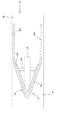
ガイド板6は、図2、3に示すように、平面視で略V字状の板状体である先細り部6aと、この先細り部6aから後方へ延設し且つ掘削溝Hの溝壁Wに当接する当接部6bと、先細り部6aの内側に沿って設けられた平面視略V字の板状の内板6cとを有している。
先細り部6aは、前にいくほど平面視で幅狭となるように支柱5に取り付けられ、上縁が前にいくにしたがって低くなっている。したがって、ガイド板6は、掘削溝H内にある耕耘された土を掻き分けながら土中を前進しやすいと共に、土中を前進させるとガイド部4に下向きの力が働き、走行中にロータリ機枠22が持ち上がることはなく、ロータリ耕耘部9の耕深や、畝立て成型器41による畝Uの高さが一定に保たれる。
As shown in FIGS. 2 and 3, the
The tapered
当接部6bは、先細り部6aの左右後端から対地作業装置1の前後方向に沿ってそれぞれ延びた平坦な部分であり、この平坦な当接部6bを持つことでガイド板6が溝壁Wに当接して掘削溝Hにならいやすく(つまり、ガイド板6の延設方向が掘削溝Hの長手方向に略沿いやすく)なる。左右の各当接部6b間の距離(ガイド板6の左右幅)は掘削溝Hの溝幅に略同じ又は若干狭く設定されていて、掘削溝Hにならっていた一方の当接部6bが溝壁Wから離れても、他方の当接部6bが反対側の溝壁Wに当接するため、ガイド部4の左右方向の中心がつねに掘削溝Hの幅中心に略合うこととなる。
The
内板6cは、先端の内側が支柱5下部の前の角に当たった状態で、後部の内側が支柱5の下端部から左右外方に延びた棒状の支持材54の先端に固定されている。この内板6cに先細り部6aがネジ又はピン等の固定具6dによって取り付けられることで、ガイド板6が支柱5の下部に固定されている。よって、土中を前進することで摩耗したガイド板6を交換でき、さらに、挿入する掘削溝Hごとに溝幅に応じた左右幅を持つガイド板6に取り換えることも可能となっている。
第1実施形態の対地作業装置1の使用態様を図5にて示す。
The
The usage aspect of the
まず、周囲に掘削爪を付けた円盤を回転させるロータリ式等のトレンチャーによって、圃場Fの土を掘って幅狭で深い掘削溝Hを形成する(掘削作業A)。
この掘削溝HをトラクタTで跨ぎ、ガイド部4が掘削溝Hに挿入されるように対地作業装置1を下ろす。このとき畝立て作業部2のロータリ耕耘部9はガイド部4の前方で掘削溝Hを跨ぐこととなり、この状態でトラクタTを前進させて掘削溝Hの上部を耕耘する(耕耘作業B)。
さらに、ロータリ耕耘部9の後方にある案内板40によって、放ちくされた耕耘された土が中央に集められ、その土が畝立て成型器41をくぐることで畝立てがなされる(畝立て成型作業C)と同時に、成型される畝U内に播種手段7の案内部46からリリースされるシーダテープPが所定の深さで埋設されることで、畝U内で一定間隔ごとに種子Qを播く(播種作業D1)。
First, a narrow and deep excavation groove H is formed by digging the soil of the field F by a rotary type trencher that rotates a disk with excavating claws around it (excavation operation A).
The
Further, by the
上述したように、播種手段7の案内部46における吐出口46bの左右位置は、ガイド部4のガイド板6の左右方向の中心と略合うように設定されており、ガイド部4を掘削作業Aで掘った掘削溝Hに挿入されて溝壁WにならわせながらトラクタTを前進させて対地作業装置1を牽引するだけで、播種手段7における畝幅方向の播種位置(作業位置S)とを、掘削溝Hの幅中心に略合わせることができる。
したがって、作業者は、すでに成型された掘削溝Hに沿って播種作業D1を容易に行うことが可能となる。
As described above, the left and right positions of the
Therefore, the operator can easily perform the sowing operation D1 along the already formed excavation groove H.
さらに、ロータリ耕耘部9による耕耘幅の中心や畝立て成型器41の幅中心も、ガイド部4のガイド板6の左右方向の中心と略合うように設定されているので、ガイド部4を掘削溝Hに挿入されて溝壁Wにならわせながら対地作業装置1を牽引するだけで、耕耘作業Bによる耕耘幅の中心や畝立て成型作業Cで成型される畝Uの幅中心を掘削溝Hの幅中心に略合わせることが可能となり、掘削溝Hに沿った耕耘作業B、畝立て成型作業C及び播種作業D1(対地作業D)を同時且つ容易に行うことができる。
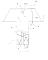
図8は、第2実施形態に係る対地作業装置1と、この対地作業装置1に取り付けられたガイド部4を示している。
Furthermore, since the center of the tilling width by the
FIG. 8 shows the
第2実施形態における違いは、対畝作業部3として、播種手段7の替わりに移植手段8を備えている点と、ガイド部4のガイド板6の形状が異なっている点である。
移植手段8は、ツールバー36に設けられた植付機55を有していて、苗供給機からの苗Nを畝Uに移植する。
植付機55は、上部の支持筒56と、この支持筒56の下方に位置する前後に開閉自在な植付カップ(開口器)57とを備えている。
この植付カップ57は、閉じた状態で、下方に向けて先窄まり状の略円錐状に形成された上方開放状のカップ状に形成されて内部に苗Nを収容保持可能とされ、開いた状態で苗Nを下方に落下放出可能とされている。また、この植付カップ57は、苗Nを略没入状とする植付穴を形成するために、下方から上方に向かうにしたがって大きくなるように形成されている。
The difference in the second embodiment is that the opposite working
The transplanting means 8 has a
The
The
また、植付カップ57から放出された苗Nの落下位置は、対地作業装置1の左右方向の中心と略一致しており、ガイド部4を掘削溝Hに挿入して溝壁Wにならわせながら対地作業装置1を前進させるだけで、移植手段8における畝幅方向の移植位置(作業位置S)を、掘削溝Hの幅中心とを略合わせることができる。
したがって、作業者は、掘削溝Hに沿って移植作業D2(対地作業D)を容易に行え、さらに掘削溝Hに沿った耕耘作業B及び畝立て成型作業Cも同時に行うことができる。
第2実施形態に係るガイド部4のガイド板6は、図8に示したように、正面視で略ハの字形状となるように、下方にいくにしたがって幅広に形成されている。
Moreover, the fall position of the seedling N discharged from the
Therefore, the operator can easily perform the transplanting operation D2 (ground operation D) along the excavation groove H, and can also perform the tilling operation B and the upright molding operation C along the excavation groove H at the same time.
As shown in FIG. 8, the
これによって、土中で前進させるガイド部4に対して下向きのより大きい力が働き、対地作業装置1の走行中においてロータリ機枠22の持ち上がりがより抑えられ、ロータリ耕耘部9の耕深や畝立て成型器41による畝Uの高さに対する影響がさらになくなる。
なお、本発明は、前述した実施形態に限定されるものではない。対地作業装置1等の各構成又は全体の構造、形状、寸法などは、本発明の趣旨に沿って適宜変更することができる。
対地作業装置1は、対畝作業部3の畝幅方向の作業位置Sがガイド部4の左右位置に略合う(つまり、掘削溝Hの幅中心に略合う)のであれば、ロータリ耕耘部9による耕耘幅の中心や畝立て成型器41等によって成型された畝Uの幅中心が掘削溝Hの幅中心と略合っていなくてもよい。
As a result, a greater downward force is exerted on the
In addition, this invention is not limited to embodiment mentioned above. Each structure of the
If the work position S in the dredging width direction of the facing
また、対地作業装置1の左右方向の中心に対して、ガイド部4の左右位置、対畝作業部3の畝幅方向の作業位置S、ロータリ耕耘部9による耕耘幅の中心及び畝立て成型器41の幅中心が略合うように設定してもよく、このとき対地作業装置1の左右中心を含め全てが掘削溝Hの幅中心に略合うこととなる。
畝立て作業部2は、ロータリ耕耘部9を有さないものとしてもよく、この場合は掘削作業A後にロータリ耕耘機にて圃場Fを耕耘してから、対地作業装置1を用いて畝立て成型作業C及び対地作業Dを行うこととなる。
Further, with respect to the center in the left-right direction of the
The upright work unit 2 may not have the
対畝作業部3は、播種手段7や移植手段8でなく、マルチフィルム敷設手段や施肥手段などであってもよい。
ガイド部4は、畝立て作業部2内のツールバー36に取り付けられていなくとも、播種手段7、移植手段8などの対畝作業部3から下方に突出して設けられていてもよい。
ガイド板6は、掘削溝Hの溝壁Wにそれぞれが当接可能な左右一対の板状体で構成されていてもよい。
播種手段7の案内部46は、長手方向に沿って前側にアングル状の土掘削用板を取り付け、畝U内で土をスムーズに掻き分けながらシーダテープPを埋設していくこととしてもよい。
The opposing working
The
The
The
案内部46の下端は、シーダテープPを送り出しやすいように後方へ湾曲してもよい。
The lower end of the
1 対地作業装置
2 畝立て作業部
3 対畝作業部
4 ガイド部
5 支柱
6 ガイド板
7 播種手段
8 移植手段
9 ロータリ耕耘部
H 掘削溝
T トラクタ
U 畝
D 対地作業
S 対地作業の作業位置
W 掘削溝の溝壁
N 苗
DESCRIPTION OF
Claims (5)
前記対畝作業部(3)による畝(U)の幅方向での作業位置(S)を前記掘削溝(H)の幅中心に略合わせるべく、前記掘削溝(H)に挿入されて溝壁(W)により案内されるガイド部(4)を前記畝立て作業部(2)又は対畝作業部(3)から下方に突出して設けていることを特徴とする対地作業装置。 A vertical working section (2) that is mounted on a tractor (T) that runs over an elongated excavated groove (H) that is continuously excavated and that performs vertical molding on the excavated groove (H); A ground work device including a ground work unit (3) for performing ground work (D) on the molded basket (U),
The groove wall is inserted into the excavation groove (H) so that the work position (S) in the width direction of the trough (U) by the counter work portion (3) is substantially aligned with the width center of the excavation groove (H). A ground work device characterized in that a guide part (4) guided by (W) is provided so as to protrude downward from the upright work part (2) or the face work part (3).
Priority Applications (1)
| Application Number | Priority Date | Filing Date | Title |
|---|---|---|---|
| JP2009145381A JP5050004B2 (en) | 2009-06-18 | 2009-06-18 | Ground working equipment |
Applications Claiming Priority (1)
| Application Number | Priority Date | Filing Date | Title |
|---|---|---|---|
| JP2009145381A JP5050004B2 (en) | 2009-06-18 | 2009-06-18 | Ground working equipment |
Publications (2)
| Publication Number | Publication Date |
|---|---|
| JP2011000046A JP2011000046A (en) | 2011-01-06 |
| JP5050004B2 true JP5050004B2 (en) | 2012-10-17 |
Family
ID=43558541
Family Applications (1)
| Application Number | Title | Priority Date | Filing Date |
|---|---|---|---|
| JP2009145381A Active JP5050004B2 (en) | 2009-06-18 | 2009-06-18 | Ground working equipment |
Country Status (1)
| Country | Link |
|---|---|
| JP (1) | JP5050004B2 (en) |
Cited By (2)
| Publication number | Priority date | Publication date | Assignee | Title |
|---|---|---|---|---|
| JP2016002052A (en) * | 2014-06-18 | 2016-01-12 | 株式会社クボタ | Work machine |
| KR101847531B1 (en) | 2018-02-05 | 2018-04-10 | 이학남 | Ridge plowing and Vinyl-coating machine |
Families Citing this family (11)
| Publication number | Priority date | Publication date | Assignee | Title |
|---|---|---|---|---|
| JP6040734B2 (en) * | 2012-11-28 | 2016-12-07 | 井関農機株式会社 | Working machine |
| JP6131594B2 (en) * | 2012-12-27 | 2017-05-24 | 井関農機株式会社 | Agricultural machine |
| JP6352093B2 (en) * | 2014-07-25 | 2018-07-04 | 鋤柄農機株式会社 | 畦 Forming equipment |
| JP6193821B2 (en) * | 2014-08-08 | 2017-09-06 | ヤンマー株式会社 | Working machine |
| JP6336407B2 (en) * | 2015-03-11 | 2018-06-06 | ヤンマー株式会社 | Agricultural machine |
| JP6078120B2 (en) * | 2015-08-07 | 2017-02-08 | ヤンマー株式会社 | Working machine |
| JP6530294B2 (en) * | 2015-09-30 | 2019-06-12 | 株式会社クボタ | Transplanter |
| JP6530295B2 (en) * | 2015-09-30 | 2019-06-12 | 株式会社クボタ | Transplanter |
| CN105794368B (en) * | 2016-03-22 | 2018-01-09 | 四川农业大学 | A kind of shallow raw groove cultivating and growing special-purpose machinery of Chinese yam |
| KR102116184B1 (en) * | 2018-10-17 | 2020-05-27 | 김재동 | Combined seeder and ridger for soybean in paddy soil |
| KR102234303B1 (en) * | 2018-12-14 | 2021-03-31 | 대한민국 | Combined seeder and ridger for soybean in paddy soil, having rotary blades for forming ridge |
Family Cites Families (4)
| Publication number | Priority date | Publication date | Assignee | Title |
|---|---|---|---|---|
| JPS55104805A (en) * | 1979-02-02 | 1980-08-11 | Kubota Ltd | Multiple seeder for farming |
| JPH1094305A (en) * | 1996-09-25 | 1998-04-14 | Yanmar Agricult Equip Co Ltd | Transplanter of yam or the like |
| JP2002262612A (en) * | 2001-03-07 | 2002-09-17 | Tsutomu Tomabechi | Work machine for seeding |
| JP2005192417A (en) * | 2003-12-26 | 2005-07-21 | Toshiro Shimomura | Transplanter and transplantation working vehicle equipped with the same |
-
2009
- 2009-06-18 JP JP2009145381A patent/JP5050004B2/en active Active
Cited By (2)
| Publication number | Priority date | Publication date | Assignee | Title |
|---|---|---|---|---|
| JP2016002052A (en) * | 2014-06-18 | 2016-01-12 | 株式会社クボタ | Work machine |
| KR101847531B1 (en) | 2018-02-05 | 2018-04-10 | 이학남 | Ridge plowing and Vinyl-coating machine |
Also Published As
| Publication number | Publication date |
|---|---|
| JP2011000046A (en) | 2011-01-06 |
Similar Documents
| Publication | Publication Date | Title |
|---|---|---|
| JP5050004B2 (en) | Ground working equipment | |
| CA2766804C (en) | Depth adjustment assembly for a disc opener of an agricultural implement | |
| CA2598431A1 (en) | Combined agricultural machine | |
| BRPI0617848A2 (en) | plow and method for making a plow | |
| CN109068584B (en) | Sugarcane transplanting machine | |
| JP6040734B2 (en) | Working machine | |
| KR20090040581A (en) | Minimum tillage seeder | |
| KR20070093944A (en) | A seeding machine | |
| CN114128450B (en) | Pumpkin seeding and film mulching integrated equipment | |
| JP2013039086A (en) | Burdock sowing molding machine | |
| JP2013039086A5 (en) | ||
| JP6173825B2 (en) | A direct sowing machine that can directly sow dry rice fields in the early days after rainfall. | |
| KR100696246B1 (en) | Machine for direct sowing of rice on well-drained paddy field | |
| US8220559B2 (en) | Plough assembly for deep soil cultivation | |
| JP6175412B2 (en) | Working machine | |
| JP6193821B2 (en) | Working machine | |
| CA2996482C (en) | Residue management tool for seeders | |
| JP6131594B2 (en) | Agricultural machine | |
| JP6910501B2 (en) | Sugar cane transplanter | |
| EP4169362A1 (en) | Agricultural and forestry implement for planting and fertilising | |
| JP6545642B2 (en) | Work machine | |
| JP7204836B2 (en) | sugarcane transplanter | |
| KR20140013511A (en) | Apparatus for forming small furrow in ridge | |
| CN209806379U (en) | A irrigation ditch ridging, fertilization integrated device for seedling planting | |
| JP6078120B2 (en) | Working machine |
Legal Events
| Date | Code | Title | Description |
|---|---|---|---|
| A621 | Written request for application examination |
Free format text: JAPANESE INTERMEDIATE CODE: A621 Effective date: 20110922 |
|
| A977 | Report on retrieval |
Free format text: JAPANESE INTERMEDIATE CODE: A971007 Effective date: 20120710 |
|
| TRDD | Decision of grant or rejection written | ||
| A01 | Written decision to grant a patent or to grant a registration (utility model) |
Free format text: JAPANESE INTERMEDIATE CODE: A01 Effective date: 20120717 |
|
| A01 | Written decision to grant a patent or to grant a registration (utility model) |
Free format text: JAPANESE INTERMEDIATE CODE: A01 |
|
| A61 | First payment of annual fees (during grant procedure) |
Free format text: JAPANESE INTERMEDIATE CODE: A61 Effective date: 20120723 |
|
| FPAY | Renewal fee payment (event date is renewal date of database) |
Free format text: PAYMENT UNTIL: 20150727 Year of fee payment: 3 |
|
| R150 | Certificate of patent or registration of utility model |
Ref document number: 5050004 Country of ref document: JP Free format text: JAPANESE INTERMEDIATE CODE: R150 Free format text: JAPANESE INTERMEDIATE CODE: R150 |