JP5034026B2 - 光ファイバジャイロ - Google Patents
光ファイバジャイロ Download PDFInfo
- Publication number
- JP5034026B2 JP5034026B2 JP2007209339A JP2007209339A JP5034026B2 JP 5034026 B2 JP5034026 B2 JP 5034026B2 JP 2007209339 A JP2007209339 A JP 2007209339A JP 2007209339 A JP2007209339 A JP 2007209339A JP 5034026 B2 JP5034026 B2 JP 5034026B2
- Authority
- JP
- Japan
- Prior art keywords
- laser beam
- phase
- optical fiber
- optical
- coupler
- Prior art date
- Legal status (The legal status is an assumption and is not a legal conclusion. Google has not performed a legal analysis and makes no representation as to the accuracy of the status listed.)
- Expired - Fee Related
Links
- 239000000835 fiber Substances 0.000 title description 4
- 230000003287 optical effect Effects 0.000 claims description 79
- 239000013307 optical fiber Substances 0.000 claims description 57
- 230000008878 coupling Effects 0.000 claims description 8
- 238000010168 coupling process Methods 0.000 claims description 8
- 238000005859 coupling reaction Methods 0.000 claims description 8
- 230000005284 excitation Effects 0.000 claims description 6
- 239000004065 semiconductor Substances 0.000 description 9
- 230000010355 oscillation Effects 0.000 description 8
- 239000000463 material Substances 0.000 description 6
- 230000000644 propagated effect Effects 0.000 description 5
- VYPSYNLAJGMNEJ-UHFFFAOYSA-N Silicium dioxide Chemical compound O=[Si]=O VYPSYNLAJGMNEJ-UHFFFAOYSA-N 0.000 description 4
- 230000035559 beat frequency Effects 0.000 description 4
- 230000005540 biological transmission Effects 0.000 description 4
- 238000000034 method Methods 0.000 description 4
- 238000012545 processing Methods 0.000 description 4
- 238000001514 detection method Methods 0.000 description 3
- 230000010287 polarization Effects 0.000 description 3
- 238000010894 electron beam technology Methods 0.000 description 2
- 238000002474 experimental method Methods 0.000 description 2
- 239000011521 glass Substances 0.000 description 2
- 230000001678 irradiating effect Effects 0.000 description 2
- 238000005259 measurement Methods 0.000 description 2
- 229910004298 SiO 2 Inorganic materials 0.000 description 1
- 150000004770 chalcogenides Chemical class 0.000 description 1
- 238000012937 correction Methods 0.000 description 1
- 230000000694 effects Effects 0.000 description 1
- 239000000284 extract Substances 0.000 description 1
- 230000006870 function Effects 0.000 description 1
- 229910010272 inorganic material Inorganic materials 0.000 description 1
- 239000011147 inorganic material Substances 0.000 description 1
- 239000011368 organic material Substances 0.000 description 1
- 238000005498 polishing Methods 0.000 description 1
- 230000001902 propagating effect Effects 0.000 description 1
Images
Landscapes
- Gyroscopes (AREA)
Description
本発明の光ファイバジャイロは、光ファイバ、レーザ光励起手段、結合手段、第1および第2の分岐器、第1および第2の結合器、ならびに、第1および第2の光検出器を備える。
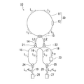
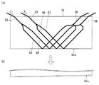
本発明の光ファイバジャイロの一例の構成を、図1に模式的に示す。図1の光ファイバジャイロは、環状の光ファイバ11と、光ファイバ11の両端に結合された半導体光増幅器12と、結合器13と、光ファイバ14〜20と、分岐器21および22と、可変位相器23と、結合器24および25と、フォトダイオード26および27とを備える。
i2=I0cos(kΔP+2πΔft+φ)・・・(1)
i2=−I0sin(2πΔft)
i2=I0sin(2πΔft)
11、14、15、16、17、18、19、20 光ファイバ
12 半導体光増幅器
13、24、25 結合器
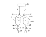
21、22 分岐器
26、27 フォトダイオード
52〜59 光導波路
L1、L2、L11、L12、L21、L22 レーザ光
Claims (4)
- 環状に配置された光ファイバと、
前記光ファイバの両端に結合され、前記光ファイバ内を互いに逆方向に進行するレーザ光L1およびL2を発生させるレーザ光励起手段と、
前記光ファイバから、前記レーザ光L1の一部および前記レーザ光L2の一部を引き出す結合手段と、
引き出された前記レーザ光L1をレーザ光L11とレーザ光L12とに分岐する第1の分岐器と、
引き出された前記レーザ光L2をレーザ光L21とレーザ光L22とに分岐する第2の分岐器と、
前記レーザ光L11と前記レーザ光L21とを結合する第1の結合器と、
前記レーザ光L12と前記レーザ光L22とを結合する第2の結合器と、
結合された前記レーザ光L11と前記レーザ光L21とを検波する第1の光検出器と、
結合された前記レーザ光L12と前記レーザ光L22とを検波する第2の光検出器とを備え、
前記第1の光検出器で検出される第1の信号の位相と、前記第2の光検出器で検出される第2の信号の位相との差が、10°〜170°または−10°〜−170°の範囲にある光ファイバジャイロ。 - 前記第1の信号の位相と前記第2の信号の位相との差が、45°〜135°または−45°〜−135°の範囲にある請求項1に記載の光ファイバジャイロ。
- 前記第1の分岐器と前記第1の結合器との間の光路、前記第1の分岐器と前記第2の結合器との間の光路、前記第2の分岐器と前記第1の結合器との間の光路、および前記第2の分岐器と前記第2の結合器との間の光路から選ばれる少なくとも1つの光路に、可変位相器を備える請求項1または2に記載の光ファイバジャイロ。
- 前記第1の信号の位相と前記第2の信号の位相との差を制御するために屈折率が変化させられた領域を、前記第1の分岐器と前記第1の結合器との間の光路、前記第1の分岐器と前記第2の結合器との間の光路、前記第2の分岐器と前記第1の結合器との間の光路、および前記第2の分岐器と前記第2の結合器との間の光路から選ばれる少なくとも1つの光路に備える請求項1または2に記載の光ファイバジャイロ。
Priority Applications (1)
| Application Number | Priority Date | Filing Date | Title |
|---|---|---|---|
| JP2007209339A JP5034026B2 (ja) | 2007-08-10 | 2007-08-10 | 光ファイバジャイロ |
Applications Claiming Priority (1)
| Application Number | Priority Date | Filing Date | Title |
|---|---|---|---|
| JP2007209339A JP5034026B2 (ja) | 2007-08-10 | 2007-08-10 | 光ファイバジャイロ |
Publications (2)
| Publication Number | Publication Date |
|---|---|
| JP2009042153A JP2009042153A (ja) | 2009-02-26 |
| JP5034026B2 true JP5034026B2 (ja) | 2012-09-26 |
Family
ID=40443031
Family Applications (1)
| Application Number | Title | Priority Date | Filing Date |
|---|---|---|---|
| JP2007209339A Expired - Fee Related JP5034026B2 (ja) | 2007-08-10 | 2007-08-10 | 光ファイバジャイロ |
Country Status (1)
| Country | Link |
|---|---|
| JP (1) | JP5034026B2 (ja) |
Families Citing this family (2)
| Publication number | Priority date | Publication date | Assignee | Title |
|---|---|---|---|---|
| JP5275886B2 (ja) * | 2009-04-20 | 2013-08-28 | ミネベア株式会社 | 半導体リングレーザジャイロ |
| DE102016200503A1 (de) * | 2016-01-16 | 2017-07-20 | Robert Bosch Gmbh | Vorrichtung und Verfahren zum Erzeugen von Licht mittels eines Leuchtstoffs |
Family Cites Families (7)
| Publication number | Priority date | Publication date | Assignee | Title |
|---|---|---|---|---|
| US4662751A (en) * | 1985-09-24 | 1987-05-05 | The United States Of America As Represented By The Administrator Of The National Aeronautics And Space Administration | Closed loop fiber optic rotation sensor |
| JPS6329211A (ja) * | 1986-07-23 | 1988-02-06 | Mitsubishi Electric Corp | 光フアイバ回転センサ |
| JPH02147908A (ja) * | 1988-11-30 | 1990-06-06 | Oki Electric Ind Co Ltd | 光ファイバジャイロ |
| US5116132A (en) * | 1990-01-12 | 1992-05-26 | Litton Systems, Inc. | Ring laser gyroscope output optics detection system |
| US5189487A (en) * | 1991-11-21 | 1993-02-23 | Litton Systems, Inc. | Multioscillator ring laser gyroscope local oscillator-based output optics detection system |
| JPH07146150A (ja) * | 1993-11-24 | 1995-06-06 | Hitachi Ltd | 光ファイバリングレーザジャイロ |
| US6650682B1 (en) * | 1999-04-30 | 2003-11-18 | University Of New Mexico | Bi-directional short pulse ring laser |
-
2007
- 2007-08-10 JP JP2007209339A patent/JP5034026B2/ja not_active Expired - Fee Related
Also Published As
| Publication number | Publication date |
|---|---|
| JP2009042153A (ja) | 2009-02-26 |
Similar Documents
| Publication | Publication Date | Title |
|---|---|---|
| Dell’Olio et al. | Miniaturization of interferometric optical gyroscopes: a review | |
| Boes et al. | Status and potential of lithium niobate on insulator (LNOI) for photonic integrated circuits | |
| JP2722005B2 (ja) | 偏波回転リング経路を有する受動リング共振器ジヤイロ | |
| Bergh et al. | An overview of fiber-optic gyroscopes | |
| US8744222B2 (en) | Practical silicon photonic multi-function integrated-optic chip for fiber sensor applications | |
| Mahmoud et al. | Novel on chip rotation detection based on the acousto-optic effect in surface acoustic wave gyroscopes | |
| EP3475758A1 (en) | Nonreciprocal light propagation systems and methods | |
| JP3692474B2 (ja) | 光ファイバジャイロ | |
| JPS61230024A (ja) | フアイバ光学回転センサ | |
| US12332057B2 (en) | Chip-integrated optical rotation rate sensor | |
| JP2779704B2 (ja) | スペクトル変化系誤差の制御 | |
| CN112710294B (zh) | 一种低光学噪声的双环并联谐振式陀螺系统及方法 | |
| Li et al. | Test and analysis of the optical Kerr-effect in resonant micro-optic gyros | |
| JP2007139780A (ja) | 自由空間共振器を備える光ジャイロおよび慣性回転速度を感知する方法 | |
| JP2526143B2 (ja) | 光ファイバ回転検出システム | |
| Vannahme et al. | Integrated optical Ti: LiNbO3 ring resonator for rotation rate sensing | |
| CN116086425B (zh) | 一种基于特殊镜像环结构的干涉式光纤陀螺 | |
| JP5034026B2 (ja) | 光ファイバジャイロ | |
| Ning et al. | Waveguide-type optical passive ring resonator gyro using frequency modulation spectroscopy technique | |
| US7924427B2 (en) | Photonic crystal based rotation sensor | |
| JP2017015576A (ja) | サニャック干渉型光電流センサ及びその信号処理方法 | |
| Gu et al. | Angular velocity sensing based on double-ring slow-light structure | |
| JP2011242173A (ja) | 光ファイバジャイロの偏波安定化方法及びその装置 | |
| EP3792595B1 (en) | Resonator fiber optic gyroscope with integrated photonics interface | |
| CN103047980A (zh) | 再入式光纤陀螺 |
Legal Events
| Date | Code | Title | Description |
|---|---|---|---|
| A621 | Written request for application examination |
Free format text: JAPANESE INTERMEDIATE CODE: A621 Effective date: 20100701 |
|
| TRDD | Decision of grant or rejection written | ||
| A977 | Report on retrieval |
Free format text: JAPANESE INTERMEDIATE CODE: A971007 Effective date: 20120425 |
|
| A01 | Written decision to grant a patent or to grant a registration (utility model) |
Free format text: JAPANESE INTERMEDIATE CODE: A01 Effective date: 20120501 |
|
| A01 | Written decision to grant a patent or to grant a registration (utility model) |
Free format text: JAPANESE INTERMEDIATE CODE: A01 |
|
| A61 | First payment of annual fees (during grant procedure) |
Free format text: JAPANESE INTERMEDIATE CODE: A61 Effective date: 20120530 |
|
| FPAY | Renewal fee payment (event date is renewal date of database) |
Free format text: PAYMENT UNTIL: 20150713 Year of fee payment: 3 |
|
| R150 | Certificate of patent or registration of utility model |
Ref document number: 5034026 Country of ref document: JP Free format text: JAPANESE INTERMEDIATE CODE: R150 Free format text: JAPANESE INTERMEDIATE CODE: R150 |
|
| R250 | Receipt of annual fees |
Free format text: JAPANESE INTERMEDIATE CODE: R250 |
|
| R250 | Receipt of annual fees |
Free format text: JAPANESE INTERMEDIATE CODE: R250 |
|
| R250 | Receipt of annual fees |
Free format text: JAPANESE INTERMEDIATE CODE: R250 |
|
| R250 | Receipt of annual fees |
Free format text: JAPANESE INTERMEDIATE CODE: R250 |
|
| R250 | Receipt of annual fees |
Free format text: JAPANESE INTERMEDIATE CODE: R250 |
|
| LAPS | Cancellation because of no payment of annual fees |