JP5031769B2 - Tripod device with grip function using ball and socket joint - Google Patents
Tripod device with grip function using ball and socket joint Download PDFInfo
- Publication number
- JP5031769B2 JP5031769B2 JP2008548496A JP2008548496A JP5031769B2 JP 5031769 B2 JP5031769 B2 JP 5031769B2 JP 2008548496 A JP2008548496 A JP 2008548496A JP 2008548496 A JP2008548496 A JP 2008548496A JP 5031769 B2 JP5031769 B2 JP 5031769B2
- Authority
- JP
- Japan
- Prior art keywords
- socket
- main body
- flexible
- ball
- tripod device
- Prior art date
- Legal status (The legal status is an assumption and is not a legal conclusion. Google has not performed a legal analysis and makes no representation as to the accuracy of the status listed.)
- Expired - Fee Related
Links
- 239000002344 surface layer Substances 0.000 claims description 12
- 229920002994 synthetic fiber Polymers 0.000 claims description 2
- 238000003780 insertion Methods 0.000 description 5
- 230000037431 insertion Effects 0.000 description 5
- 239000000463 material Substances 0.000 description 4
- 238000009941 weaving Methods 0.000 description 4
- 239000000853 adhesive Substances 0.000 description 2
- 230000001070 adhesive effect Effects 0.000 description 2
- 230000003746 surface roughness Effects 0.000 description 2
- 229920004943 Delrin® Polymers 0.000 description 1
- 239000004677 Nylon Substances 0.000 description 1
- 125000000218 acetic acid group Chemical group C(C)(=O)* 0.000 description 1
- 238000005452 bending Methods 0.000 description 1
- 239000011230 binding agent Substances 0.000 description 1
- 210000000078 claw Anatomy 0.000 description 1
- 150000001875 compounds Chemical class 0.000 description 1
- 238000010586 diagram Methods 0.000 description 1
- 230000005489 elastic deformation Effects 0.000 description 1
- 239000010410 layer Substances 0.000 description 1
- 239000000314 lubricant Substances 0.000 description 1
- 230000001050 lubricating effect Effects 0.000 description 1
- 238000000034 method Methods 0.000 description 1
- 229920001778 nylon Polymers 0.000 description 1
- 239000004033 plastic Substances 0.000 description 1
- 238000000926 separation method Methods 0.000 description 1
Images


Classifications
-
- F—MECHANICAL ENGINEERING; LIGHTING; HEATING; WEAPONS; BLASTING
- F16—ENGINEERING ELEMENTS AND UNITS; GENERAL MEASURES FOR PRODUCING AND MAINTAINING EFFECTIVE FUNCTIONING OF MACHINES OR INSTALLATIONS; THERMAL INSULATION IN GENERAL
- F16M—FRAMES, CASINGS OR BEDS OF ENGINES, MACHINES OR APPARATUS, NOT SPECIFIC TO ENGINES, MACHINES OR APPARATUS PROVIDED FOR ELSEWHERE; STANDS; SUPPORTS
- F16M11/00—Stands or trestles as supports for apparatus or articles placed thereon ; Stands for scientific apparatus such as gravitational force meters
- F16M11/20—Undercarriages with or without wheels
- F16M11/24—Undercarriages with or without wheels changeable in height or length of legs, also for transport only, e.g. by means of tubes screwed into each other
- F16M11/40—Undercarriages with or without wheels changeable in height or length of legs, also for transport only, e.g. by means of tubes screwed into each other by means of coilable or bendable legs or spiral shaped legs
-
- F—MECHANICAL ENGINEERING; LIGHTING; HEATING; WEAPONS; BLASTING
- F16—ENGINEERING ELEMENTS AND UNITS; GENERAL MEASURES FOR PRODUCING AND MAINTAINING EFFECTIVE FUNCTIONING OF MACHINES OR INSTALLATIONS; THERMAL INSULATION IN GENERAL
- F16M—FRAMES, CASINGS OR BEDS OF ENGINES, MACHINES OR APPARATUS, NOT SPECIFIC TO ENGINES, MACHINES OR APPARATUS PROVIDED FOR ELSEWHERE; STANDS; SUPPORTS
- F16M11/00—Stands or trestles as supports for apparatus or articles placed thereon ; Stands for scientific apparatus such as gravitational force meters
- F16M11/02—Heads
- F16M11/04—Means for attachment of apparatus; Means allowing adjustment of the apparatus relatively to the stand
- F16M11/06—Means for attachment of apparatus; Means allowing adjustment of the apparatus relatively to the stand allowing pivoting
- F16M11/12—Means for attachment of apparatus; Means allowing adjustment of the apparatus relatively to the stand allowing pivoting in more than one direction
- F16M11/14—Means for attachment of apparatus; Means allowing adjustment of the apparatus relatively to the stand allowing pivoting in more than one direction with ball-joint
-
- F—MECHANICAL ENGINEERING; LIGHTING; HEATING; WEAPONS; BLASTING
- F16—ENGINEERING ELEMENTS AND UNITS; GENERAL MEASURES FOR PRODUCING AND MAINTAINING EFFECTIVE FUNCTIONING OF MACHINES OR INSTALLATIONS; THERMAL INSULATION IN GENERAL
- F16C—SHAFTS; FLEXIBLE SHAFTS; ELEMENTS OR CRANKSHAFT MECHANISMS; ROTARY BODIES OTHER THAN GEARING ELEMENTS; BEARINGS
- F16C11/00—Pivots; Pivotal connections
- F16C11/04—Pivotal connections
- F16C11/06—Ball-joints; Other joints having more than one degree of angular freedom, i.e. universal joints
- F16C11/0661—Ball-joints; Other joints having more than one degree of angular freedom, i.e. universal joints the two co-operative parts each having both convex and concave interfaces
-
- F—MECHANICAL ENGINEERING; LIGHTING; HEATING; WEAPONS; BLASTING
- F16—ENGINEERING ELEMENTS AND UNITS; GENERAL MEASURES FOR PRODUCING AND MAINTAINING EFFECTIVE FUNCTIONING OF MACHINES OR INSTALLATIONS; THERMAL INSULATION IN GENERAL
- F16M—FRAMES, CASINGS OR BEDS OF ENGINES, MACHINES OR APPARATUS, NOT SPECIFIC TO ENGINES, MACHINES OR APPARATUS PROVIDED FOR ELSEWHERE; STANDS; SUPPORTS
- F16M11/00—Stands or trestles as supports for apparatus or articles placed thereon ; Stands for scientific apparatus such as gravitational force meters
- F16M11/02—Heads
- F16M11/16—Details concerning attachment of head-supporting legs, with or without actuation of locking members thereof
-
- F—MECHANICAL ENGINEERING; LIGHTING; HEATING; WEAPONS; BLASTING
- F16—ENGINEERING ELEMENTS AND UNITS; GENERAL MEASURES FOR PRODUCING AND MAINTAINING EFFECTIVE FUNCTIONING OF MACHINES OR INSTALLATIONS; THERMAL INSULATION IN GENERAL
- F16M—FRAMES, CASINGS OR BEDS OF ENGINES, MACHINES OR APPARATUS, NOT SPECIFIC TO ENGINES, MACHINES OR APPARATUS PROVIDED FOR ELSEWHERE; STANDS; SUPPORTS
- F16M11/00—Stands or trestles as supports for apparatus or articles placed thereon ; Stands for scientific apparatus such as gravitational force meters
- F16M11/02—Heads
- F16M11/18—Heads with mechanism for moving the apparatus relatively to the stand
-
- F—MECHANICAL ENGINEERING; LIGHTING; HEATING; WEAPONS; BLASTING
- F16—ENGINEERING ELEMENTS AND UNITS; GENERAL MEASURES FOR PRODUCING AND MAINTAINING EFFECTIVE FUNCTIONING OF MACHINES OR INSTALLATIONS; THERMAL INSULATION IN GENERAL
- F16M—FRAMES, CASINGS OR BEDS OF ENGINES, MACHINES OR APPARATUS, NOT SPECIFIC TO ENGINES, MACHINES OR APPARATUS PROVIDED FOR ELSEWHERE; STANDS; SUPPORTS
- F16M11/00—Stands or trestles as supports for apparatus or articles placed thereon ; Stands for scientific apparatus such as gravitational force meters
- F16M11/20—Undercarriages with or without wheels
- F16M11/2007—Undercarriages with or without wheels comprising means allowing pivoting adjustment
- F16M11/2035—Undercarriages with or without wheels comprising means allowing pivoting adjustment in more than one direction
- F16M11/2078—Undercarriages with or without wheels comprising means allowing pivoting adjustment in more than one direction with ball-joint
-
- F—MECHANICAL ENGINEERING; LIGHTING; HEATING; WEAPONS; BLASTING
- F16—ENGINEERING ELEMENTS AND UNITS; GENERAL MEASURES FOR PRODUCING AND MAINTAINING EFFECTIVE FUNCTIONING OF MACHINES OR INSTALLATIONS; THERMAL INSULATION IN GENERAL
- F16M—FRAMES, CASINGS OR BEDS OF ENGINES, MACHINES OR APPARATUS, NOT SPECIFIC TO ENGINES, MACHINES OR APPARATUS PROVIDED FOR ELSEWHERE; STANDS; SUPPORTS
- F16M13/00—Other supports for positioning apparatus or articles; Means for steadying hand-held apparatus or articles
- F16M13/02—Other supports for positioning apparatus or articles; Means for steadying hand-held apparatus or articles for supporting on, or attaching to, an object, e.g. tree, gate, window-frame, cycle
- F16M13/022—Other supports for positioning apparatus or articles; Means for steadying hand-held apparatus or articles for supporting on, or attaching to, an object, e.g. tree, gate, window-frame, cycle repositionable
-
- G—PHYSICS
- G03—PHOTOGRAPHY; CINEMATOGRAPHY; ANALOGOUS TECHNIQUES USING WAVES OTHER THAN OPTICAL WAVES; ELECTROGRAPHY; HOLOGRAPHY
- G03B—APPARATUS OR ARRANGEMENTS FOR TAKING PHOTOGRAPHS OR FOR PROJECTING OR VIEWING THEM; APPARATUS OR ARRANGEMENTS EMPLOYING ANALOGOUS TECHNIQUES USING WAVES OTHER THAN OPTICAL WAVES; ACCESSORIES THEREFOR
- G03B17/00—Details of cameras or camera bodies; Accessories therefor
- G03B17/56—Accessories
- G03B17/561—Support related camera accessories
-
- F—MECHANICAL ENGINEERING; LIGHTING; HEATING; WEAPONS; BLASTING
- F16—ENGINEERING ELEMENTS AND UNITS; GENERAL MEASURES FOR PRODUCING AND MAINTAINING EFFECTIVE FUNCTIONING OF MACHINES OR INSTALLATIONS; THERMAL INSULATION IN GENERAL
- F16M—FRAMES, CASINGS OR BEDS OF ENGINES, MACHINES OR APPARATUS, NOT SPECIFIC TO ENGINES, MACHINES OR APPARATUS PROVIDED FOR ELSEWHERE; STANDS; SUPPORTS
- F16M11/00—Stands or trestles as supports for apparatus or articles placed thereon ; Stands for scientific apparatus such as gravitational force meters
- F16M11/02—Heads
- F16M11/04—Means for attachment of apparatus; Means allowing adjustment of the apparatus relatively to the stand
- F16M11/041—Allowing quick release of the apparatus
-
- Y—GENERAL TAGGING OF NEW TECHNOLOGICAL DEVELOPMENTS; GENERAL TAGGING OF CROSS-SECTIONAL TECHNOLOGIES SPANNING OVER SEVERAL SECTIONS OF THE IPC; TECHNICAL SUBJECTS COVERED BY FORMER USPC CROSS-REFERENCE ART COLLECTIONS [XRACs] AND DIGESTS
- Y10—TECHNICAL SUBJECTS COVERED BY FORMER USPC
- Y10T—TECHNICAL SUBJECTS COVERED BY FORMER US CLASSIFICATION
- Y10T403/00—Joints and connections
- Y10T403/32—Articulated members
- Y10T403/32008—Plural distinct articulation axes
- Y10T403/32032—Plural ball and socket
Landscapes
- Engineering & Computer Science (AREA)
- General Engineering & Computer Science (AREA)
- Mechanical Engineering (AREA)
- Physics & Mathematics (AREA)
- General Physics & Mathematics (AREA)
- Pivots And Pivotal Connections (AREA)
- Accessories Of Cameras (AREA)
- Mutual Connection Of Rods And Tubes (AREA)
- Clamps And Clips (AREA)
- Connection Of Plates (AREA)
Description
本発明は、相互接続することによってフレキシブル(変形可能)な組立体となる接続具に関するものであり、より具体的には、ボール及びソケットジョイントによる接続具を用いた取付装置に関するものである。 The present invention relates to a connector that becomes a flexible (deformable) assembly by being interconnected, and more specifically, to an attachment device using a connector using a ball and a socket joint.
典型的な三脚は、すそ広がりに開かれた3本の堅い脚を備えて、カメラのような装置類の支持構造を形成する。典型的な三脚の脚部には通常は柔軟性がなく、地面あるいは他の平らな面から離れた支持を提供するのに適応させられたものである。ある三脚においては、脚部の長さについてのいくつかの調節部を有し、三脚が設置された面においての平面の偏りが考慮されるものである。 A typical tripod comprises three rigid legs that are open at the flank to form a support structure for devices such as cameras. A typical tripod leg is usually not flexible and is adapted to provide support away from the ground or other flat surface. Some tripods have several adjustments for the length of the legs, taking into account the flatness of the plane on which the tripod is installed.
このような三脚は、カメラのような装置を支持する方法において制限を受けるものである。そこで、三脚として機能しうると共に、縦材に対して取付けられてグリップマウント(滑り止め把持)による取付として機能しうる取付装置が求められる。 Such tripods are limited in how they support devices such as cameras. Therefore, there is a demand for an attachment device that can function as a tripod and can be attached to a vertical member and function as attachment by a grip mount (non-slip grip).
本発明は、相互に接続されたときに、フレキシブルな組立体を形成するボール及びジョイント接続具についての発明である。各接続具は、第1の端部及び第2の端部を伴う本体を有する。外部ソケット係合表層は本体の一方の端部に設けられる。本体のもう一方の端部は、内部キャビティを有する。ひとつの接続具のソケット係合表層は、他の接続具の内部キャビティへ嵌め込まれて、接続具を相互に接続する。 The present invention is a ball and joint connector that forms a flexible assembly when connected to each other. Each connector has a body with a first end and a second end. The outer socket engaging surface layer is provided at one end of the main body. The other end of the body has an internal cavity. The socket engagement surface of one connector is fitted into the internal cavity of the other connector to connect the connectors together.
ある実施例において、ボール及びソケットジョイント接続具は、前記接続具の外側周囲に余剰に形成された細長い領域を利用して、それにより滑り止めて把持を容易にするものである。前述のボール及びソケットジョイント接続具を利用する他の典型的な実施例において、取付装置は、ボール及びジョイント接続具から構成される脚を用いて支持するものである。 In one embodiment, the ball and socket joint connector utilizes an elongated area formed excessively around the outside of the connector, thereby preventing slipping and facilitating gripping. In another exemplary embodiment utilizing the aforementioned ball and socket joint connector, the attachment device is supported using a leg comprised of the ball and joint connector.
図1は、本発明の実施例による、複数の接続された接続具の側面図を示す。
図2は、本発明の実施例による、複数の接続された接続具の端面図を示す。
図3は、本発明の実施例による、複数の接続された接続具の断面図である。
図4は、本発明の実施例による、接続具の側面図である。
図5は、本発明の実施例による、接続具の断面図である。
図6は、本発明の実施例による、滑り止め部を備えた接続具を示す。
図7は、本発明の実施例による、グリップ部を備えた接続具の側面図である。
図8は、本発明の実施例による、グリップ部を備えた接続具の断面図である。
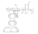
図9は、本発明の実施例による、三脚装置の説明図である。
図10は、本発明の実施例による三脚装置の本体と相互接続部の説明図である。図11は、本発明の実施例による三脚装置の本体と相互接続部の断面図である。図12は、本発明の実施例による三脚装置の説明図である。
図13は、本発明の実施例による三脚装置の本体と相互接続部の側面図及び断面図である。
図14は、本発明の実施例による三脚装置の本体と相互接続部の側面図及び断面図である。
図15は、本発明の実施例による三脚装置の本体と相互接続部の側面図及び断面図である。
FIG. 1 shows a side view of a plurality of connected fittings according to an embodiment of the present invention.
FIG. 2 shows an end view of a plurality of connected fittings according to an embodiment of the present invention.
FIG. 3 is a cross-sectional view of a plurality of connected fittings according to an embodiment of the present invention.
FIG. 4 is a side view of a connector according to an embodiment of the present invention.
FIG. 5 is a cross-sectional view of a connector according to an embodiment of the present invention.
FIG. 6 shows a connector with a non-slip portion according to an embodiment of the present invention.
FIG. 7 is a side view of a connector having a grip portion according to an embodiment of the present invention.
FIG. 8 is a cross-sectional view of a connector having a grip portion according to an embodiment of the present invention.
FIG. 9 is an illustration of a tripod device according to an embodiment of the present invention.
Figure 10 is an explanatory view of the main body and the interconnect of the tripod apparatus according to an embodiment of the present invention. Figure 11 is a cross-sectional view of the body and interconnects the tripod apparatus according to an embodiment of the present invention. FIG. 12 is an explanatory diagram of a tripod device according to an embodiment of the present invention.
Figure 13 is a side view and a cross-sectional view of the body and interconnects the tripod apparatus according to an embodiment of the present invention.
Figure 14 is a side view and a sectional view of the body and interconnects the tripod apparatus according to an embodiment of the present invention.
Figure 15 is a side view and a sectional view of the body and interconnects the tripod apparatus according to an embodiment of the present invention.
図1、図2、図3は、本発明の実施例による、複数のボール及びソケットジョイントによる接続具101を示す。接続具101は、第1の端部102と第2の端部103を備えている。ソケット係合端部表層104は、第1の端部102に設けられる。第1の端部102は、実体的にはくぼんだ状態である。
1, 2 and 3 show a
第2の端部103には、内部ソケット受けキャビティ107を備えた本体106がある。内部ソケット受けキャビティ107の内側表面110は、次の接続具101のソケット係合端部表層104又は同様のソケット係合端部層を伴う次の構成要素をすっぽりと包んで適合するように調整される。首部105は第2の端部103から第1の端部102を分けるものである。停止節108は、一組のボール及びソケットジョイント接続具が角度を超過して、意図せぬ分離が生じる危険性を防ぐための停止機構として機能する。
At the
図4及び図5に示されるように、実施例において、接続具101には、基礎軸111がある。実施例において、接続具101は基礎軸111を中心とした対称形とするとよい。実施例において、接続具の第1の端部と第2の端部のそれぞれの末端面は、基礎軸111に対して垂直とするとよい。
As shown in FIGS. 4 and 5, in the embodiment, the
本発明の実施例において、前記内部ソケット受けキャビティ又は/及びソケット係合端部表層の壁の厚さは、ボール及びソケットジョイント接続具が接続された後に締まりばめが残るように構成される。実施例において、締まりばめは、材料が塑性限界以下でありクリープ限界以上である圧力レベルによって圧迫されるようにして製作される。該材料はその後、締まりばめがクリープ限界点以下となるまで、典型的には用いられる材料の弾性変形圧力範囲の上限より下の範囲で、クリープ変形しうるものである。複数の接続具が相互に接続されて長いチェーンが形成された実施例において、この圧力は、異なる接続具の組間において均等化するものである。また、この圧力の均等化により、さまざまな接続具の組間における摩擦抵抗が均等化するものである。複数の接続された接続具の長いチェーンにおける接続具の組間での摩擦抵抗の均等化により、前記チェーンが曲がる力を受けた際に前記接続具の前記チェーンが円滑な流れで曲がるようになるものである。例えば、45度の角度へ曲げられた10ユニットのチェーンにおいては、その曲がりは接続具の組間に十分に広がり渡って分散される。 In an embodiment of the present invention, the wall thickness of the inner socket receiving cavity or / and the socket engaging end surface is configured such that an interference fit remains after the ball and socket joint fitting is connected. In an embodiment, the interference fit is made such that the material is compressed by a pressure level that is below the plastic limit and above the creep limit. The material is then capable of creep deformation, typically below the upper limit of the elastic deformation pressure range of the material used, until the interference fit is below the creep limit. In embodiments where multiple connectors are connected together to form a long chain, this pressure is equalized between different sets of connectors. In addition, this equalization of pressure equalizes the frictional resistance between the various sets of connectors. Equalizing frictional resistance between sets of connectors in a long chain of multiple connected connectors allows the chain of connectors to bend with a smooth flow when subjected to bending forces on the chain Is. For example, in a 10 unit chain bent to an angle of 45 degrees, the bend is well spread across the set of connectors.
図6、図7及び図8に示されるように、ある実施例では、接続具120はグリップ部122を有するものである。該接続具120は、第1の端部125及び第2の端部123を備えている。ソケット係合端部表層124は、第1の端部125に設けられる。前記第1の端部125は実体的にはくぼみをつけられたものである。
As shown in FIGS. 6, 7, and 8, in one embodiment, the
第2の端部123は、内部ソケット受けキャビティ130を伴う本体121を備える。該内部ソケット受けキャビティ130の内側表面129は、次の接続具又は同様のソケット係合端部表層を伴う次の部品に適合するように調整される。首部128は、第2の端部123から第1の端部125を分けるものである。グリップ部122は、前記接続具が表面をより容易にとらえるようにする。ある実施例では、グリップ部は接続具本体に共に成形される。ある実施例では、グリップ部はゴム引き合成材により構成される。ある実施例では、グリップ部は、接続具の外側表面に成形された円周リングである。接続具が対象物上に接して設置される又は対象物を包み込むときに、前記グリップ部によってより高い摩擦抵抗が生じる。
The
本発明のある実施例では、ソケット係合端部表層104の外側表面109に注油してもよい。ソケット係合端部表層104の外側表面109への注油により、接続具によるチェーンにおける多種多様な接続間の抵抗がより均一となり得る。ある実施例では、前記内部ソケット受けキャビティ107の内側表面110に注油してもよい。前記内部ソケット受けキャビティ107の内部表面110への注油により、抵抗がより均一となり得る。ある実施例においては、ソケット係合端部表層104の外側表面109と、前記内部ソケット受けキャビティ107の内部表面の双方に注油してもよい。ある実施例では、これらの表面を、粘着剤を用いて覆ってもよい。アセチル系材料、デルリン(登録商標)、ナイロンのような結合材を伴うことで、通常は粘着剤として用いられる化合物は、ボール及びソケットジョイント接続具の締まりばめに用いられた際に、潤滑剤として機能しうる。
In some embodiments of the present invention, the
本発明のある実施例において、前記ソケット係合端部表層104の外側表面109は、織り込まれてもよい。また、その織り込みが、表面の粗さとなって現れてもよい。前記ソケット係合端部表層104の外側表面109の織り込みにより、接続具のチェーンにおけるさまざまな接続を通じて、抵抗がより均一となり得る。ある実施例において、内部ソケット受けキャビティ107の内側表面110は、織り込まれてもよい。また、その織り込みは、表面の粗さとなって現れてもよい。前記内部ソケット受けキャビティ107の内部表面110の織り込みにより、抵抗がより均一となり得る。ある実施例においては、ソケット係合端部表層104の外側表面109と、前記内部ソケット受けキャビティ107の内側表面110の双方に注油してもよい。
In an embodiment of the present invention, the
図3は、複数のボール及びソケットジョイント接続具の断面図を示す。本発明の実施例において、停止突起108は、内部ソケット受けキャビティの中に備えられる。2つの接続具が相互に関連する特定の角度に達した際に、前記ソケット係合端部表層104の内側縁部140は、停止突起108と接触するように調整される。該停止突起108と該内側縁部140との接触は、相互に関連した2片の接続具の角度超過に関する停止機構として作用する。この停止機構の機能は、2つの接続具における過剰な回転と脱落の危険性を防ぐように作用するものである。
FIG. 3 shows a cross-sectional view of a plurality of ball and socket joint connectors. In an embodiment of the present invention, the
図9は、本発明のある実施例による三脚装置200を示す。本体部201は、3本のフレキシブルレッグ202,203,204の支持する基台となる。該フレキシブルレッグ202,203,204は、一連の相互に連結したボール及びソケットジョイント接続具により構成される。前記フレキシブルレッグは、多様な位置方向に曲げられることが可能であり、また、三脚支持を形成することによって本体部201を支持するのに用いられることが可能である。前記フレキシブルレッグは、平坦でない面に適応可能であり、これにより三脚装置はさまざまな状況において機能することが可能となる。ここでは説明のために3本の脚が用いられるが、ある実施例においては、より多くの脚が設けられてもよい。図9に示されるように、本体部201自体に一連の相互に連結されたボール及びソケットジョイント接続具を組み込んで設けることで、その取付機能の観点から、より多くの曲順応性を持たせることが可能である。
FIG. 9 illustrates a
図7において、フレキシブルレッグは脚部の機能をするものとして示されているが、典型的な三脚装置による固定では適合しないような対象物に対して本発明による三脚装置を固定することを目的とし、該脚部は十分な曲動自在性を備え、該脚部は棒状や他の対象物のような様々なものの周囲を包み込んで用いることが可能である。グリップ部と共に用いることで、前記三脚装置はさまざまな対象物に固定取付されることが可能である。例えば、デジタルカメラの位置固定に用いられる際には、前記脚部は垂直な門の柵を囲むように包み込むことが可能となり、以前は利用不可能であった写真撮影機会においてのカメラの固定取付を利用可能とするものである。 In FIG. 7, the flexible leg is shown as acting as a leg, but it is intended to fix the tripod device according to the present invention to an object that is not compatible with fixing with a typical tripod device. The leg portion has sufficient flexibility, and the leg portion can be used by wrapping around a variety of objects such as a rod or other objects. By using it with a grip part, the tripod device can be fixedly attached to various objects. For example, when used to fix the position of a digital camera, the legs can be wrapped around a vertical gate fence, and the camera can be fixedly mounted on a photo opportunity that was previously unavailable. Is made available.
ある実施例において、本体部201は、相互接続部205に接続される。クリップ220は、前記相互接続部205に対して着脱可能に固定される。ある実施例において、該クリップ220には、取付用ねじ山を設けて、カメラや他の装置に適合するようにしてもよい。
In some embodiments, the
ある実施例においては、フレキシブルレッグ202,203,204は、共に成型されたグリップ部208を有する複数の接続具を用いてもよい。該グリップ部208は、さまざまな方法による三脚装置の使用を可能にするものであり、柱状物や他の対象物の周囲を脚部が取り囲むことも可能にするものである。ある実施例において、フレキシブルレッグは、グリップポッド207によって終端処理されてもよい。図3における断面図に示されるように、該グリップポッド207は、前記接続具のキャビティ内に完全に充填又は密着するようにしてもよい。ある実施例においては、それぞれの脚部の末端の接続具には、その第1の端部にソケット係合端部表層があり、その第2の端部に吸着カップが備えられる。該吸着カップにより、三脚装置200を多様な表面へ確実に取付ることが可能となる。
In some embodiments, the
図9,図10,図11においてさらに示された本発明のある実施例において、前記相互接続部205は、クリップ220を受けるように調整されたものである。該クリップ220は、相互接続部205の挿入部227へ挿入するのに適したレール228を有するとよい。該クリップ220は、ばね搭載レバー222上の爪部225によって満たされるように適合した凹部226を有するとよい。該クリップは、相互接続部205に対して着脱可能に取り付けられ、前記レバー222を押すことによって開放されうる。ある実施例において、前記レバー222は、前記クリップがスライド挿入されて接する前記相互接続部205における挿入方向と同じ側に設けられる。他の実施例においては、前記レバー222は、前記クリップ220がスライド挿入される前記相互接続部205における挿入方向と反対の側に設けられる。
In one embodiment of the present invention further illustrated in FIGS. 9, 10, and 11, the
ある実施例において、固定用ねじ221は、クリップ220に固定されてもよい。ある実施例において、ねじ223は、標準的なサイズであってカメラを取り付けるためのねじ山を設けるとよい。ある実施例において、ねじ221の頭部223は、凹部の成形されたわずかな隆起によって凹部224に支持されてもよい。
In an embodiment, the fixing
図12,図13,図14,及び図15で示される本発明の実施例において、三脚装置500は、本体部501を利用し、該本体部は、三脚装置の脚部を間隔を空けて位置付けて、該脚部を異なった形状として利用する。本体部ソケット502の間隔を空けることにより、三脚の脚部の有効な利用を可能となり、三脚の脚部を取付アームとして用いる際により有効な使用が可能となる。ある実施例において、前記本体ソケット502は本体部501の中心の周囲に等間隔に配置される。前記本体ソケットは、地面に対する角度はすそ広がりである(典型的使用法)。ある実施例では、該角度は45度に広げられた角度である。本体ソケットをすそ広がりにしたことにより、三脚装置の脚部にとっての潜在的な巻き包み角度は異なる様々な範囲において可能となる。
In the embodiment of the present invention shown in FIGS. 12, 13, 14, and 15, the
本体ソケットをすそ広がりにしたことによって、本発明による三脚装置の脚部は典型的な三脚装置のように利用することも可能である。脚部を形成する前記本体ソケットと前記接続具の動作範囲は、脚部の垂直的な位置取りをもさらに可能にしたものである。このように、前記本体部501は、三脚としての通常の機能性を保持するものである。一方で、すそ広がりにしたことにより、垂直な棒状物のようなものに巻きつけてくるんだ場合のように脚部を滑り止め把持アームとして用いた場合に、該脚部をより大きく曲げることを可能としたものである。このように、本体部501は、この装置によって楽しむことのできる配置位置の範囲と使用例の種類を増加させるものである。
By extending the body socket, the legs of the tripod device according to the present invention can be used like a typical tripod device. The operation range of the main body socket and the connection tool forming the leg portion further enables the vertical positioning of the leg portion. As described above, the
上記の記述から明白なように、ここに示された説明からさまざまな実施が構成され得る。さらに、この技術に関する技術者においては、追加的な利点や改善が容易に生じ得る。従って、本願発明の広義の側面においては、描写及び記述された具体的な説明及び実例に制限されるものではない。結果的に、出願人による概括的発明の概念又は範囲領域から逸脱することなく、このような具体的な説明からの逸脱が為されうる。 As is apparent from the above description, various implementations may be constructed from the description provided herein. Furthermore, additional advantages and improvements can readily occur to those skilled in the art. Accordingly, the broad aspects of the present invention are not limited to the specific descriptions and examples depicted and described. Consequently, departures from such specific descriptions may be made without departing from the general inventive concept or scope of the applicant.
101,120 接続具
102,125 第1の端部
103,123 第2の端部
104 ソケット係合端部表層
105 首部
106 本体
107 内部ソケット受けキャビティ
108 停止突起
109 外側表面
110 内側表面
111 初期軸
122 滑り止め把持部
140 内側縁部
200 三脚装置
201 本体部
202,203,204 フレキシブルレッグ
205 相互接続部
207 滑り止め把持閉止部
220 クリップ
221 取付ねじ
222 レバー
223 ヘッド
224,226 凹部
225 爪部
227 挿入部
228 レール
DESCRIPTION OF SYMBOLS 101,120 Connector 102,125 1st edge part 103,123
Claims (12)
前記本体部の下方に接続された複数のフレキシブルレッグと、
前記本体部の上方に接続された相互接続部と、
前記相互接続部に取り外し可能に設けられたクリップとを備えた三脚装置において、
前記フレキシブルレッグは、ソケット係合端部表層と内部ソケット受けキャビティとを備えたボール及びソケットジョイント接続具を一連に複数連結することでフレキシブルレッグとして構成され、前記ボール及びソケットジョイント接続具のソケット部にはグリップ部が一体に形成されたことを特徴とする三脚装置。The main body,
A plurality of flexible legs connected below the main body;
An interconnect connected above the body;
In a tripod device comprising a clip detachably provided in the interconnecting portion,
The flexible leg is configured as a flexible leg by connecting a plurality ball and socket joint connector and a socket engaging end surface and the inner portion the socket receiving cavity in a series, the socket of the ball and socket joint connector tripod apparatus characterized by grip portion is formed integrally with the part.
前記複数のフレキシブルレッグは、ソケット係合端部表層と内部ソケット受けキャビティとを備えたボール及びソケットジョイント接続具を一連に複数連結することでフレキシブルレッグとして構成されると共に、前記フレキシブルレッグは第1の端部と第2の端部を備えて、前記フレキシブルレッグの第1の端部が前記本体部に接続され、
前記ボール及びソケットジョイント接続具は、第1の端部と第2の端部を備えて前記第1の端部から前記第2の端部まで伸びた長手方向軸とを有する接続具本体と、前記第1の端部において外側表層となるソケット係合端部表層と、前記第2の端部における内部ソケット受けキャビティとを備えると共に、前記ボール及びソケットジョイント接続具のソケット部にはグリップ部が一体に形成され、
前記本体部は、複数の内部ソケット受けキャビティを備え、該複数の内部ソケット受けキャビティは、前記フレキシブルレッグの可動範囲が最大となるよう、垂直方向に対してすそ広がりの方向に備えられて、前記複数のフレキシブルレッグの第1の端部を斜め方向から受けることを特徴とする三脚装置。In a tripod device comprising a main body, a plurality of flexible legs connected to the main body, and an interconnection connected to the main body,
It said plurality of flexible legs with configured as a flexible leg by connecting a plurality ball and socket joint connector and a socket engaging end surface and the inner portion the socket receiving cavity in a series, the flexible leg first The first end of the flexible leg is connected to the main body,
The ball and socket joint connector comprises a connector body having a first end and a second end and a longitudinal axis extending from the first end to the second end; a socket engaging end surface of the outer surface at the first end, the second with and an internal socket receiving cavity at the end of the ball and socket joint connector of the socket portion grip portion Is integrally formed,
The main body includes a plurality of internal socket receiving cavities, and the plurality of internal socket receiving cavities are provided in a flaring direction with respect to a vertical direction so that the movable range of the flexible leg is maximized, A tripod device for receiving first ends of a plurality of flexible legs from an oblique direction.
前記フレキシブルレッグは、ソケット係合端部表層と内部ソケット受けキャビティとを備えたボール及びソケットジョイント接続具を一連に複数連結することでフレキシブルレッグとして構成されると共に、前記ボール及びソケットジョイント接続具のソケット部にはグリップ部が一体に形成され、前記フレキシブルレッグは第1の端部と第2の端部を有し、前記フレキシブルレッグの第1の端部が前記本体部に接続され、
前記相互接続部は、内部ソケット受けキャビティを有する第1の端部と、第2の端部を有することを特徴とする三脚装置。In a tripod device comprising a main body, a plurality of flexible legs connected to the main body, and an interconnection connected to the main body,
The flexible legs with configured as a flexible leg by connecting a plurality ball and socket joint connector and a socket engaging end surface and the inner portion the socket receiving cavity in a series, the ball and socket joint connector the socket portion grip portion are integrally formed, the flexible legs having a first end and a second end, the first end portion of said flexible leg is connected to the main body portion,
A tripod device wherein the interconnect has a first end having an internal socket receiving cavity and a second end.
前記相互接続部はさらに着脱可能なクリップを設けると共に該クリップを捕らえるように調整されたタブを備えて、前記クリップの受け部はさらに平坦面を有して前記タブは該平坦面に突出し、前記タブを受けるように調整された前記クリップはそのボトム表面にスロットを有し、
前記ばね搭載レバーは、前記相互接続部のピボットの周囲で回転することを特徴とする三脚装置。In claim 9, the second end portion of the interconnect portion is provided with a detachable clip receiving portion, and the interconnect portion is further provided with a spring mounting lever,
The interconnect further comprises a detachable clip and a tab adjusted to capture the clip, the receiving portion of the clip further having a flat surface, the tab projecting into the flat surface, The clip adjusted to receive the tab has a slot on its bottom surface;
The tripod device, wherein the spring loaded lever rotates about a pivot of the interconnect.
前記本体部には、複数の内部ソケット受けキャビティがそれぞれ相互にすそ広がりの角度をなすように前記本体部の下方表面に斜め下方向に向けて形成されると共に、ソケット係合端部表面が前記本体部の上方表面に形成され、
前記複数のフレキシブルレッグは、ソケット係合端部表層と内部ソケット受けキャビティとを備えたボール及びソケットジョイント接続具を複数連結することで一連のフレキシブルレッグとして構成されると共に、前記ボール及びソケットジョイント接続具のソケット部にはグリップ部が一体に形成され、前記複数のフレキシブルレッグはそれぞれ第1の端部と第2の端部を有し、前記第1の端部が、前記本体部に接続されることを特徴とする三脚装置。In a tripod device comprising a main body and a plurality of flexible legs,
In the main body, a plurality of internal socket receiving cavities are formed obliquely downward on the lower surface of the main body so as to form an angle of expansion with respect to each other. Formed on the upper surface of the main body,
Said plurality of flexible legs with constructed as a series of flexible legs by several connecting a ball and socket joint connector and a socket engaging end surface and the inner portion the socket receiving cavity, said ball and socket joint the socket portion of the connector grip portion are integrally formed, the plurality of flexible legs having each a first end and a second end, said first end, said body portion A tripod device that is connected.
Applications Claiming Priority (3)
| Application Number | Priority Date | Filing Date | Title |
|---|---|---|---|
| US11/324,994 | 2006-01-03 | ||
| US11/324,994 US20070154254A1 (en) | 2006-01-03 | 2006-01-03 | Mounting apparatus using ball and socket joints with gripping features |
| PCT/US2006/021703 WO2007081388A2 (en) | 2006-01-03 | 2006-06-06 | Mounting apparatus using ball and socket joints with gripping features |
Publications (3)
| Publication Number | Publication Date |
|---|---|
| JP2009522516A JP2009522516A (en) | 2009-06-11 |
| JP2009522516A5 JP2009522516A5 (en) | 2011-05-06 |
| JP5031769B2 true JP5031769B2 (en) | 2012-09-26 |
Family
ID=38224571
Family Applications (1)
| Application Number | Title | Priority Date | Filing Date |
|---|---|---|---|
| JP2008548496A Expired - Fee Related JP5031769B2 (en) | 2006-01-03 | 2006-06-06 | Tripod device with grip function using ball and socket joint |
Country Status (10)
| Country | Link |
|---|---|
| US (5) | US20070154254A1 (en) |
| EP (1) | EP1969244B8 (en) |
| JP (1) | JP5031769B2 (en) |
| KR (1) | KR20090016441A (en) |
| CN (1) | CN101194127B (en) |
| AU (1) | AU2006335293A1 (en) |
| CA (1) | CA2649539C (en) |
| DE (1) | DE202006021110U1 (en) |
| TW (1) | TW200804712A (en) |
| WO (1) | WO2007081388A2 (en) |
Families Citing this family (100)
| Publication number | Priority date | Publication date | Assignee | Title |
|---|---|---|---|---|
| US20100308198A1 (en) * | 2006-01-03 | 2010-12-09 | Bevirt Joeben | Mounting Apparatus Using Flexible Joints With Magnetic Atachment |
| US8297566B2 (en) * | 2006-01-03 | 2012-10-30 | Day Men US, Inc | Mounting apparatus using ball and socket joints with composite connectors |
| US20070154254A1 (en) * | 2006-01-03 | 2007-07-05 | Bevirt Joeben | Mounting apparatus using ball and socket joints with gripping features |
| US20080056808A1 (en) * | 2006-01-03 | 2008-03-06 | Bevirt Joeben | Monopod mounting apparatus |
| US8251536B2 (en) * | 2006-01-03 | 2012-08-28 | Daymen Us, Inc. | Flashlight with mounting apparatus |
| US20070152117A1 (en) * | 2006-01-04 | 2007-07-05 | Byrd Randel L | Viscoelastic Mounting Device |
| US20080265111A1 (en) * | 2007-04-27 | 2008-10-30 | Tocad America, Inc. | Apparatuses and systems for supporting and positioning cameras and other equipment |
| US20090039213A1 (en) * | 2007-04-27 | 2009-02-12 | Richard Darrow | Apparatuses and systems for supporting and positioning cameras and other equipment |
| US20080283697A1 (en) * | 2007-04-27 | 2008-11-20 | Richard Darrow | Apparatuses and systems for supporting and positioning cameras and other equipment |
| US8197149B2 (en) * | 2007-04-27 | 2012-06-12 | Tocad America, Inc. | Apparatuses and systems for supporting and positioning cameras and other equipment |
| CN101644296B (en) * | 2008-08-08 | 2012-01-25 | 鸿富锦精密工业(深圳)有限公司 | Connection unit and ball joints thereof |
| US8087836B2 (en) * | 2008-12-15 | 2012-01-03 | Joby Photo, Inc. | Miniature mounting apparatus |
| US20100221062A1 (en) * | 2008-12-29 | 2010-09-02 | Bevirt Joeben | Ball and Socket Connectors With Substructure |
| DE212010000043U1 (en) * | 2009-04-21 | 2012-03-14 | Uri Rapoport | Flexible segmented support structure |
| US20100294908A1 (en) * | 2009-05-21 | 2010-11-25 | Patrick Mish | BOOKSTAND FOR AN eREADER |
| CN101988615B (en) * | 2009-08-05 | 2012-08-08 | 宁波伟峰影像设备集团有限公司 | Reelable tripod |
| US20110042530A1 (en) * | 2009-08-19 | 2011-02-24 | Mark Phillips | Flexipod with flexible bendable legs with a gripping surface |
| US20120288268A1 (en) * | 2009-12-15 | 2012-11-15 | Bevirt Joeben | Miniature Mounting Apparatus |
| CN102870067B (en) | 2010-03-25 | 2016-05-11 | 诺基亚技术有限公司 | The distortion of electronic installation |
| WO2011144972A1 (en) | 2010-05-21 | 2011-11-24 | Nokia Corporation | A method, an apparatus and a computer program for controlling an output from a display of an apparatus |
| US20120019113A1 (en) * | 2010-07-26 | 2012-01-26 | Hale Eric C | Device Case and Mounting Apparatus With Flexible Support Legs |
| WO2012094069A2 (en) * | 2011-01-06 | 2012-07-12 | Barnard Brandon | Electronic device holder |
| US20120287268A1 (en) * | 2011-05-13 | 2012-11-15 | Justin Jensen | Systems and Methods for Capturing Images in Conjunction with Motion |
| US9004799B1 (en) * | 2011-08-31 | 2015-04-14 | Skylar Tibbits | Transformable linked self-assembly system |
| CN103062589A (en) * | 2011-10-21 | 2013-04-24 | 鸿富锦精密工业(深圳)有限公司 | Supporting device |
| US8620152B1 (en) | 2011-11-09 | 2013-12-31 | Rex Martin | Auxiliary lens positioning system for portable cameras |
| US8827760B2 (en) | 2011-11-28 | 2014-09-09 | Carrie Park Ushibo | Peripheral apparatus for positioning and using a portable electronic device |
| US20150351531A1 (en) * | 2011-12-21 | 2015-12-10 | Michael T. Dalton | Smartphone or tablet mounting device and method |
| US9823707B2 (en) | 2012-01-25 | 2017-11-21 | Nokia Technologies Oy | Contortion of an electronic apparatus |
| US9823696B2 (en) | 2012-04-27 | 2017-11-21 | Nokia Technologies Oy | Limiting movement |
| US9232966B2 (en) * | 2012-09-24 | 2016-01-12 | Refai Technologies, Llc | Articulating spinal rod system |
| US10016793B2 (en) | 2012-09-28 | 2018-07-10 | Thomas Engineering Solutions & Consulting, Llc | Enhanced knuckle-jointed lance useful for internal cleaning and inspection of tubulars |
| US9158332B2 (en) * | 2012-10-22 | 2015-10-13 | Nokia Technologies Oy | Limiting movement |
| US9158334B2 (en) | 2012-10-22 | 2015-10-13 | Nokia Technologies Oy | Electronic device controlled by flexing |
| TW201420933A (en) * | 2012-11-23 | 2014-06-01 | Wang xin yi | Assembling device with connection component |
| US9002458B2 (en) | 2013-06-29 | 2015-04-07 | Thync, Inc. | Transdermal electrical stimulation devices for modifying or inducing cognitive state |
| US10814131B2 (en) | 2012-11-26 | 2020-10-27 | Thync Global, Inc. | Apparatuses and methods for neuromodulation |
| US9440070B2 (en) | 2012-11-26 | 2016-09-13 | Thyne Global, Inc. | Wearable transdermal electrical stimulation devices and methods of using them |
| US10537703B2 (en) | 2012-11-26 | 2020-01-21 | Thync Global, Inc. | Systems and methods for transdermal electrical stimulation to improve sleep |
| US9399126B2 (en) | 2014-02-27 | 2016-07-26 | Thync Global, Inc. | Methods for user control of neurostimulation to modify a cognitive state |
| US9448588B2 (en) | 2012-12-12 | 2016-09-20 | Brandon Barnard | Electronic device holder |
| WO2014145323A1 (en) * | 2013-03-15 | 2014-09-18 | Cam Caddie | Camera mounting device |
| US10293161B2 (en) | 2013-06-29 | 2019-05-21 | Thync Global, Inc. | Apparatuses and methods for transdermal electrical stimulation of nerves to modify or induce a cognitive state |
| US8857775B1 (en) | 2013-07-22 | 2014-10-14 | Gopro, Inc. | Camera mount with spring clamp |
| GB2517495B (en) * | 2013-08-23 | 2015-10-21 | Daren O'sullivan | A flexible securer |
| CN107666937A (en) | 2014-05-17 | 2018-02-06 | 赛威医疗公司 | The method and apparatus that Overall waveform is applied using nerve stimulation |
| WO2015183620A2 (en) | 2014-05-25 | 2015-12-03 | Thync, Inc. | Wearable transdermal neurostimulators |
| US9333334B2 (en) | 2014-05-25 | 2016-05-10 | Thync, Inc. | Methods for attaching and wearing a neurostimulator |
| US9511395B2 (en) * | 2014-06-17 | 2016-12-06 | Thomas Engineering Solutions & Consulting, Llc | Knuckle-jointed lance segments with an exterior protective system |
| US9661197B2 (en) * | 2014-10-22 | 2017-05-23 | Gopro, Inc. | Quick-release ball-and-socket joint camera mount |
| US10088096B2 (en) * | 2014-11-13 | 2018-10-02 | Kenu, Inc. | Portable stand for electronic device |
| US11534608B2 (en) | 2015-01-04 | 2022-12-27 | Ist, Llc | Methods and apparatuses for transdermal stimulation of the outer ear |
| US10426945B2 (en) | 2015-01-04 | 2019-10-01 | Thync Global, Inc. | Methods and apparatuses for transdermal stimulation of the outer ear |
| US10258788B2 (en) | 2015-01-05 | 2019-04-16 | Thync Global, Inc. | Electrodes having surface exclusions |
| US9874305B2 (en) | 2015-02-18 | 2018-01-23 | OctoGrip, LLC | Multi-appendage device for holding, gripping, or suspending an object |
| DE102016002298A1 (en) | 2015-03-06 | 2016-09-08 | Shimano Inc. | Electric bicycle rear derailleur |
| USD758474S1 (en) | 2015-05-07 | 2016-06-07 | Gopro, Inc. | Camera mount |
| CN107847732A (en) | 2015-05-29 | 2018-03-27 | 赛威医疗公司 | Method and apparatus for transcutaneous electrostimulation |
| WO2016196635A2 (en) | 2015-06-01 | 2016-12-08 | Cerevast Medical Inc. | Apparatuses and methods for neuromodulation |
| US20170059088A1 (en) * | 2015-09-01 | 2017-03-02 | Marlon Galvez | Personal viewing of a mobile device system and method |
| US9956405B2 (en) | 2015-12-18 | 2018-05-01 | Thyne Global, Inc. | Transdermal electrical stimulation at the neck to induce neuromodulation |
| WO2017106878A1 (en) | 2015-12-18 | 2017-06-22 | Thync Global, Inc. | Apparatuses and methods for transdermal electrical stimulation of nerves to modify or induce a cognitive state |
| GB2548684A (en) * | 2016-02-05 | 2017-09-27 | Gripple Ltd | Support device for supporting a first article on a second article |
| US10646708B2 (en) | 2016-05-20 | 2020-05-12 | Thync Global, Inc. | Transdermal electrical stimulation at the neck |
| US9891509B2 (en) | 2016-06-17 | 2018-02-13 | Mimono LLC | Projector holder |
| USD782464S1 (en) | 2016-06-20 | 2017-03-28 | Paul J. Chung | Mobile device accessory with flexible neck |
| KR102582394B1 (en) | 2016-08-30 | 2023-09-26 | 삼성디스플레이 주식회사 | Semiconductor device |
| CN106287146A (en) * | 2016-10-19 | 2017-01-04 | 成都尚智恒达科技有限公司 | A kind of electronic product movable landing bracing frame of lift adjustable-angle |
| DE102016224806A1 (en) * | 2016-12-13 | 2018-06-14 | Hansgrohe Se | fastening system |
| GB2558935B (en) * | 2017-01-20 | 2020-01-29 | Sbfi Ltd | Improvements in display screen mounting |
| USD840464S1 (en) * | 2017-02-13 | 2019-02-12 | Vitec Holdings Italia Srl | Adjustable tripod |
| USD839339S1 (en) * | 2017-03-14 | 2019-01-29 | Vitec Holdings Italia Srl | Adjustable tripod |
| US10595471B2 (en) * | 2017-03-24 | 2020-03-24 | Ian Gilley | System and methods for directing plant growth |
| USD840209S1 (en) | 2017-04-21 | 2019-02-12 | Unger Marketing International, Llc | Handle |
| USD864694S1 (en) | 2017-04-21 | 2019-10-29 | Unger Marketing International, Llc | Handle |
| US11081309B2 (en) | 2017-04-21 | 2021-08-03 | Unger Marketing International, Llc | Light bulb removing and installing assemblies |
| USD843435S1 (en) * | 2017-05-16 | 2019-03-19 | Vitec Holdings Italia Srl | Pan and tilt body with device mounting clamp on a tripod |
| USD834105S1 (en) | 2017-06-01 | 2018-11-20 | Mattel-Mega Holdings (Us), Llc | Construction set element |
| USD870799S1 (en) | 2017-06-06 | 2019-12-24 | Arlo Technologies, Inc. | Flexible camera mount |
| USD829806S1 (en) * | 2017-07-21 | 2018-10-02 | Vitec Holdings Italia Srl | Mounting ring with extensions |
| USD829807S1 (en) * | 2017-07-21 | 2018-10-02 | Vitec Holdings Italia Srl | Mounting ring with extensions on a tripod |
| GB2565322B (en) | 2017-08-10 | 2021-12-01 | Atelier Volant Llc | Coupling for linkages |
| JP6512388B1 (en) | 2017-10-19 | 2019-05-15 | 日本精工株式会社 | Telescopic link and suspension |
| US10568419B2 (en) * | 2017-11-09 | 2020-02-25 | Ppj, Llc | Room caddie |
| USD872167S1 (en) * | 2017-12-12 | 2020-01-07 | Vitec Holdings Italia Srl | Tripod with clamp and extensions |
| USD890835S1 (en) | 2017-12-28 | 2020-07-21 | Gopro, Inc. | Camera |
| WO2018127888A2 (en) * | 2018-04-13 | 2018-07-12 | Instituto Panameño De Derecho Y Nuevas Tecnologías (Ipandetec) | Device as a demountable stand for photo cameras |
| WO2019209969A1 (en) | 2018-04-24 | 2019-10-31 | Thync Global, Inc. | Streamlined and pre-set neuromodulators |
| DE202019107267U1 (en) | 2018-08-07 | 2020-02-27 | Gopro, Inc. | Camera and camera holder |
| USD894256S1 (en) | 2018-08-31 | 2020-08-25 | Gopro, Inc. | Camera mount |
| USD905786S1 (en) | 2018-08-31 | 2020-12-22 | Gopro, Inc. | Camera mount |
| US10718997B2 (en) * | 2019-01-17 | 2020-07-21 | John Kiernan-Lewis | Modular tripod-arm |
| US11090189B2 (en) * | 2019-02-06 | 2021-08-17 | Earl Kelly | Eye drop alignment assembly |
| USD921095S1 (en) | 2019-06-19 | 2021-06-01 | Gopro, Inc. | Camera mount |
| USD920419S1 (en) | 2019-09-17 | 2021-05-25 | Gopro, Inc. | Camera |
| US20210262611A1 (en) * | 2020-02-24 | 2021-08-26 | Onyekachi Eke-Okoro | Apparatus and Methods using hollow figures for storing edible products at a portable electronic device |
| USD946074S1 (en) | 2020-08-14 | 2022-03-15 | Gopro, Inc. | Camera |
| USD989847S1 (en) * | 2020-11-24 | 2023-06-20 | Ningbo Yizhou Machinery Co., Ltd. | Tripod |
| CN112696579B (en) * | 2020-12-30 | 2022-05-27 | 天津市泛亚工程咨询有限公司 | Building engineering cost on-site mapping device based on BIM technology |
| CN114321579A (en) * | 2021-11-16 | 2022-04-12 | 南通佰瑞利电动工具有限公司 | A universal regulation cloud platform of spirit level for vaulting pole support |
Family Cites Families (74)
| Publication number | Priority date | Publication date | Assignee | Title |
|---|---|---|---|---|
| DE854100C (en) * | 1943-03-06 | 1952-10-30 | Ludwig Dipl-Ing Dr-Ing Grassl | Flexible bracket |
| US2684822A (en) * | 1948-10-02 | 1954-07-27 | Eugene A Odin | Supporting structure |
| FR1098836A (en) * | 1954-03-31 | 1955-08-22 | Semi-flexible tube | |
| US2824503A (en) * | 1954-09-10 | 1958-02-25 | Rollei Werke Franke Heidecke | Quick attachable mounting for photographic cameras |
| US3006052A (en) * | 1959-01-13 | 1961-10-31 | Donald B Stickney | Instrument attaching device |
| US3306634A (en) * | 1963-02-07 | 1967-02-28 | Pul Vac Inc | Articulate joint |
| US3329967A (en) * | 1965-03-31 | 1967-07-11 | Henry J Martinez | Diving suit |
| US3356325A (en) * | 1965-10-22 | 1967-12-05 | Davidson Optronics Inc | Camera-to-tripod connector |
| US3612462A (en) * | 1969-08-26 | 1971-10-12 | Quick Set Inc | Instrument mount assembly |
| US4016583A (en) * | 1975-06-24 | 1977-04-05 | Yeates Calvin B | Camera steadying device |
| US4057816A (en) * | 1976-01-13 | 1977-11-08 | Polaroid Corporation | Accessory adapter |
| US4085915A (en) * | 1977-01-11 | 1978-04-25 | Kyong Jin Song | Coupling device for equipping a camera onto the tripod |
| JPS54160147U (en) * | 1978-04-28 | 1979-11-08 | ||
| DE3011798A1 (en) * | 1980-03-27 | 1981-10-01 | Norbert Dipl.-Ing. 6000 Frankfurt Schiller | Camera or microphone stand - has legs of flexible material with lower end eyelets for securing chain |
| CH646762A5 (en) * | 1980-06-06 | 1984-12-14 | Ferag Ag | BALL JOINT LINK CHAIN. |
| US4525052A (en) * | 1983-01-27 | 1985-06-25 | Slik Tripod Co., Ltd. | Device for fixing a camera to a tripod |
| US4570887A (en) * | 1983-10-17 | 1986-02-18 | Banister Gerald K | Quick-connect mount for a camera and tripod |
| US4536116A (en) * | 1983-11-07 | 1985-08-20 | Maclean-Fogg Company | Composite molded plastic article |
| US4739801A (en) * | 1985-04-09 | 1988-04-26 | Tysubakimoto Chain Co. | Flexible supporting sheath for cables and the like |
| JPS61197395U (en) * | 1985-05-30 | 1986-12-09 | ||
| JPS6240397U (en) * | 1985-08-30 | 1987-03-10 | ||
| JPS63106993U (en) * | 1986-12-27 | 1988-07-11 | ||
| JPH01125435U (en) * | 1988-02-16 | 1989-08-28 | ||
| JPH0626799Y2 (en) * | 1989-02-28 | 1994-07-20 | 平和精機工業株式会社 | Pan head |
| JPH03129333A (en) * | 1989-10-14 | 1991-06-03 | Konica Corp | Camera tripod |
| JP2502358Y2 (en) * | 1989-12-13 | 1996-06-19 | ヤンマー農機株式会社 | Rear safety device for speed sprayer |
| JPH05145816A (en) | 1991-11-18 | 1993-06-11 | Sony Corp | Video camera system |
| USRE38897E1 (en) * | 1992-06-23 | 2005-11-29 | Elward-Louis Joint Venture | Wrappable flashlight |
| US5276596A (en) * | 1992-06-23 | 1994-01-04 | Krenzel Ronald L | Holder for a flashlight |
| US5398176A (en) * | 1993-04-19 | 1995-03-14 | Ahuja; Sushil K. | Multifunctional lamp and support |
| US5449206A (en) * | 1994-01-04 | 1995-09-12 | Lockwood Products, Inc. | Ball and socket joint with internal stop |
| FR2714863B1 (en) * | 1994-01-11 | 1996-03-29 | Facom | Tool handle. |
| US5655736A (en) * | 1994-06-30 | 1997-08-12 | Kozloff; Matthew S. | Retaining device for an electronic signalling device |
| DE9411987U1 (en) * | 1994-07-23 | 1994-09-29 | Novoflex Fotogerätebau Karl Müller, 87700 Memmingen | Device for releasably connecting a photographic or optical device to a tripod or the like. |
| US5517392A (en) * | 1994-08-05 | 1996-05-14 | Black & Decker Inc. | Sleeve retention for flexible core of a flashlight |
| JP2691869B2 (en) * | 1994-09-22 | 1997-12-17 | ハクバ写真産業株式会社 | Portable tripod |
| US5851036A (en) * | 1995-12-14 | 1998-12-22 | Vanesky; Frank W. | Permanent fitting for fluid-tight connections |
| US5997047A (en) * | 1996-02-28 | 1999-12-07 | Pimentel; Ralph | High-pressure flexible self-supportive piping assembly |
| US5647565A (en) * | 1996-03-07 | 1997-07-15 | Wei; David | Tripod |
| US5620352A (en) * | 1996-03-29 | 1997-04-15 | Tzong; Chun-Chuen | Flexible tube having a number of joints |
| WO1998009193A1 (en) * | 1996-08-27 | 1998-03-05 | Kengo Horiuchi | Camera support leg device |
| JP3083135B2 (en) * | 1996-08-27 | 2000-09-04 | 健吾 堀内 | Camera support leg |
| US5857241A (en) * | 1997-02-19 | 1999-01-12 | The Wooster Brush Company | Soft grip handle |
| US6196504B1 (en) * | 1998-07-09 | 2001-03-06 | Maurice W. Lemke | Positive-lock-and-release device for camera mounting |
| JP2000056391A (en) | 1998-07-31 | 2000-02-25 | Kanji Tomidokoro | Tripod head system for camera |
| US6173725B1 (en) * | 1999-01-19 | 2001-01-16 | Geoffrey C. Garth | Canopy structure |
| US6988846B2 (en) * | 1999-10-18 | 2006-01-24 | Philippe Vogt | Device for attaching a retaining member for an optical apparatus to a support |
| US6352227B1 (en) * | 2000-06-08 | 2002-03-05 | Clarence Eduard Hathaway | Segmented, ball jointed support |
| US6408524B1 (en) * | 2000-06-16 | 2002-06-25 | Yin-Chu Lai | Tableware grip structure with comfortable touch feeling |
| US6626210B2 (en) * | 2001-01-12 | 2003-09-30 | Water Pik, Inc. | Flexible arm assembly |
| US20030066937A1 (en) * | 2001-10-09 | 2003-04-10 | Nathan Smith | Remote control support assembly |
| US7035092B2 (en) * | 2001-11-08 | 2006-04-25 | Apple Computer, Inc. | Computer controlled display device |
| US6672788B2 (en) * | 2002-02-04 | 2004-01-06 | Clarence Eduard Hathaway | Ball joint with detent action |
| US6648376B2 (en) * | 2002-03-29 | 2003-11-18 | Showertek, Inc. | Flexible sectioned arm with internal overbending-prevention sleeves |
| DE10238706A1 (en) * | 2002-08-23 | 2004-03-11 | Pöhlmann, Werner, Dr.jur. | Camera and stand have housing joined together by adhesive arrangement, with interlinked legs |
| DE20213278U1 (en) * | 2002-08-26 | 2002-12-19 | Schrader, Peter, 44263 Dortmund | Device for holding a camera assembly on a harness |
| JP3825753B2 (en) * | 2003-01-14 | 2006-09-27 | 株式会社東芝 | Manufacturing method of semiconductor device |
| US6767153B1 (en) * | 2003-02-10 | 2004-07-27 | Dana W. Holbrook | Locking positional arm device |
| JP2004317578A (en) | 2003-04-11 | 2004-11-11 | Fujicolor Imaging Service Co Ltd | Tripod for portable telephone with camera |
| US20040211868A1 (en) * | 2003-04-24 | 2004-10-28 | Holmes Joseph T. | Webcam mount for flexible positioning |
| US6729778B1 (en) * | 2003-06-24 | 2004-05-04 | Shing Ming Wu | Fixture for fixing camera and the likes capable of adjusting the pitching angle of the camera |
| US7533906B2 (en) * | 2003-10-14 | 2009-05-19 | Water Pik, Inc. | Rotatable and pivotable connector |
| WO2005073032A1 (en) * | 2004-01-27 | 2005-08-11 | Joy Gregory T | Portable tripod and universal mounting assembly for an object |
| JP2005260522A (en) | 2004-03-11 | 2005-09-22 | Brother Ind Ltd | Image inputting device |
| US7344320B2 (en) * | 2004-03-17 | 2008-03-18 | Trek Technologies, Llc | Walking staff with tripod base and adaptable mount |
| US20050205730A1 (en) * | 2004-03-17 | 2005-09-22 | Carnevali Jeffrey D | Configurable mounting bracket |
| KR101109583B1 (en) * | 2004-11-04 | 2012-01-31 | 삼성전자주식회사 | Imaging apparatus having open/close holder part |
| US20060175482A1 (en) * | 2005-01-06 | 2006-08-10 | Joseph Johnson | Tripod head |
| US7563038B2 (en) * | 2005-06-20 | 2009-07-21 | Lino Manfrotto + Co. S.P.A. | Support for a camcorder |
| US7185862B1 (en) * | 2005-10-04 | 2007-03-06 | Jen Yu Yang | Mounting platform assembly for a stand device |
| US20070154254A1 (en) * | 2006-01-03 | 2007-07-05 | Bevirt Joeben | Mounting apparatus using ball and socket joints with gripping features |
| US8297566B2 (en) * | 2006-01-03 | 2012-10-30 | Day Men US, Inc | Mounting apparatus using ball and socket joints with composite connectors |
| US20080283697A1 (en) * | 2007-04-27 | 2008-11-20 | Richard Darrow | Apparatuses and systems for supporting and positioning cameras and other equipment |
| US20080265111A1 (en) * | 2007-04-27 | 2008-10-30 | Tocad America, Inc. | Apparatuses and systems for supporting and positioning cameras and other equipment |
-
2006
- 2006-01-03 US US11/324,994 patent/US20070154254A1/en not_active Abandoned
- 2006-06-06 WO PCT/US2006/021703 patent/WO2007081388A2/en active Application Filing
- 2006-06-06 DE DE202006021110U patent/DE202006021110U1/en not_active Expired - Lifetime
- 2006-06-06 AU AU2006335293A patent/AU2006335293A1/en not_active Abandoned
- 2006-06-06 KR KR1020087019034A patent/KR20090016441A/en not_active Application Discontinuation
- 2006-06-06 JP JP2008548496A patent/JP5031769B2/en not_active Expired - Fee Related
- 2006-06-06 CN CN2006800148816A patent/CN101194127B/en not_active Expired - Fee Related
- 2006-06-06 CA CA2649539A patent/CA2649539C/en active Active
- 2006-06-06 EP EP06772124A patent/EP1969244B8/en active Active
- 2006-07-04 TW TW095124320A patent/TW200804712A/en unknown
-
2007
- 2007-05-09 US US11/801,234 patent/US7891615B2/en active Active - Reinstated
- 2007-09-14 US US11/901,254 patent/US20080069630A1/en not_active Abandoned
-
2011
- 2011-01-14 US US13/006,434 patent/US8740160B2/en active Active - Reinstated
-
2014
- 2014-06-02 US US14/293,671 patent/US20160053935A1/en not_active Abandoned
Also Published As
| Publication number | Publication date |
|---|---|
| US20070154254A1 (en) | 2007-07-05 |
| CN101194127A (en) | 2008-06-04 |
| US20110108683A1 (en) | 2011-05-12 |
| WO2007081388A2 (en) | 2007-07-19 |
| US20160053935A1 (en) | 2016-02-25 |
| KR20090016441A (en) | 2009-02-13 |
| EP1969244B1 (en) | 2012-08-29 |
| EP1969244A4 (en) | 2010-07-21 |
| CA2649539C (en) | 2014-10-07 |
| US7891615B2 (en) | 2011-02-22 |
| EP1969244A2 (en) | 2008-09-17 |
| DE202006021110U1 (en) | 2012-09-06 |
| JP2009522516A (en) | 2009-06-11 |
| AU2006335293A1 (en) | 2007-07-19 |
| WO2007081388A3 (en) | 2007-11-01 |
| EP1969244B8 (en) | 2012-10-03 |
| TW200804712A (en) | 2008-01-16 |
| CA2649539A1 (en) | 2007-07-19 |
| US20070212163A1 (en) | 2007-09-13 |
| CN101194127B (en) | 2013-03-27 |
| US20080069630A1 (en) | 2008-03-20 |
| US8740160B2 (en) | 2014-06-03 |
Similar Documents
| Publication | Publication Date | Title |
|---|---|---|
| JP5031769B2 (en) | Tripod device with grip function using ball and socket joint | |
| US8366341B2 (en) | Attachment clips for support structures | |
| US8087836B2 (en) | Miniature mounting apparatus | |
| US20080056808A1 (en) | Monopod mounting apparatus | |
| US8297566B2 (en) | Mounting apparatus using ball and socket joints with composite connectors | |
| US8251536B2 (en) | Flashlight with mounting apparatus | |
| US20090101772A1 (en) | Level indicator clip for tripods and other structures | |
| US20100264281A1 (en) | Gripping Clip and Mounting Apparatus Using Same | |
| JP2009522516A5 (en) | ||
| US20120288268A1 (en) | Miniature Mounting Apparatus | |
| US20100308198A1 (en) | Mounting Apparatus Using Flexible Joints With Magnetic Atachment | |
| KR200399501Y1 (en) | Clamp lever for coupling | |
| CN218630487U (en) | Camera rabbit-hutch capable of adjusting gravity center | |
| JP7331464B2 (en) | lighting equipment | |
| JP5838437B1 (en) | Camera support |
Legal Events
| Date | Code | Title | Description |
|---|---|---|---|
| A621 | Written request for application examination |
Free format text: JAPANESE INTERMEDIATE CODE: A621 Effective date: 20090605 |
|
| A521 | Request for written amendment filed |
Free format text: JAPANESE INTERMEDIATE CODE: A523 Effective date: 20100607 |
|
| A521 | Request for written amendment filed |
Free format text: JAPANESE INTERMEDIATE CODE: A523 Effective date: 20100607 |
|
| A521 | Request for written amendment filed |
Free format text: JAPANESE INTERMEDIATE CODE: A523 Effective date: 20110310 |
|
| A131 | Notification of reasons for refusal |
Free format text: JAPANESE INTERMEDIATE CODE: A131 Effective date: 20110531 |
|
| A601 | Written request for extension of time |
Free format text: JAPANESE INTERMEDIATE CODE: A601 Effective date: 20110831 |
|
| A602 | Written permission of extension of time |
Free format text: JAPANESE INTERMEDIATE CODE: A602 Effective date: 20110929 |
|
| A601 | Written request for extension of time |
Free format text: JAPANESE INTERMEDIATE CODE: A601 Effective date: 20110930 |
|
| A602 | Written permission of extension of time |
Free format text: JAPANESE INTERMEDIATE CODE: A602 Effective date: 20111007 |
|
| A601 | Written request for extension of time |
Free format text: JAPANESE INTERMEDIATE CODE: A601 Effective date: 20111028 |
|
| A602 | Written permission of extension of time |
Free format text: JAPANESE INTERMEDIATE CODE: A602 Effective date: 20111107 |
|
| A521 | Request for written amendment filed |
Free format text: JAPANESE INTERMEDIATE CODE: A523 Effective date: 20111130 |
|
| A131 | Notification of reasons for refusal |
Free format text: JAPANESE INTERMEDIATE CODE: A131 Effective date: 20120110 |
|
| A521 | Request for written amendment filed |
Free format text: JAPANESE INTERMEDIATE CODE: A523 Effective date: 20120410 |
|
| TRDD | Decision of grant or rejection written | ||
| A01 | Written decision to grant a patent or to grant a registration (utility model) |
Free format text: JAPANESE INTERMEDIATE CODE: A01 Effective date: 20120529 |
|
| A01 | Written decision to grant a patent or to grant a registration (utility model) |
Free format text: JAPANESE INTERMEDIATE CODE: A01 |
|
| A61 | First payment of annual fees (during grant procedure) |
Free format text: JAPANESE INTERMEDIATE CODE: A61 Effective date: 20120627 |
|
| R150 | Certificate of patent or registration of utility model |
Ref document number: 5031769 Country of ref document: JP Free format text: JAPANESE INTERMEDIATE CODE: R150 Free format text: JAPANESE INTERMEDIATE CODE: R150 |
|
| FPAY | Renewal fee payment (event date is renewal date of database) |
Free format text: PAYMENT UNTIL: 20150706 Year of fee payment: 3 |
|
| R250 | Receipt of annual fees |
Free format text: JAPANESE INTERMEDIATE CODE: R250 |
|
| R250 | Receipt of annual fees |
Free format text: JAPANESE INTERMEDIATE CODE: R250 |
|
| R250 | Receipt of annual fees |
Free format text: JAPANESE INTERMEDIATE CODE: R250 |
|
| R250 | Receipt of annual fees |
Free format text: JAPANESE INTERMEDIATE CODE: R250 |
|
| R250 | Receipt of annual fees |
Free format text: JAPANESE INTERMEDIATE CODE: R250 |
|
| R250 | Receipt of annual fees |
Free format text: JAPANESE INTERMEDIATE CODE: R250 |
|
| R250 | Receipt of annual fees |
Free format text: JAPANESE INTERMEDIATE CODE: R250 |
|
| LAPS | Cancellation because of no payment of annual fees |