KR20090016441A - Mounting apparatus using ball and socket joints with gripping features - Google Patents
Mounting apparatus using ball and socket joints with gripping features Download PDFInfo
- Publication number
- KR20090016441A KR20090016441A KR1020087019034A KR20087019034A KR20090016441A KR 20090016441 A KR20090016441 A KR 20090016441A KR 1020087019034 A KR1020087019034 A KR 1020087019034A KR 20087019034 A KR20087019034 A KR 20087019034A KR 20090016441 A KR20090016441 A KR 20090016441A
- Authority
- KR
- South Korea
- Prior art keywords
- connector
- end portion
- gripping
- ball
- socket
- Prior art date
Links
Images


Classifications
-
- F—MECHANICAL ENGINEERING; LIGHTING; HEATING; WEAPONS; BLASTING
- F16—ENGINEERING ELEMENTS AND UNITS; GENERAL MEASURES FOR PRODUCING AND MAINTAINING EFFECTIVE FUNCTIONING OF MACHINES OR INSTALLATIONS; THERMAL INSULATION IN GENERAL
- F16M—FRAMES, CASINGS OR BEDS OF ENGINES, MACHINES OR APPARATUS, NOT SPECIFIC TO ENGINES, MACHINES OR APPARATUS PROVIDED FOR ELSEWHERE; STANDS; SUPPORTS
- F16M11/00—Stands or trestles as supports for apparatus or articles placed thereon Stands for scientific apparatus such as gravitational force meters
- F16M11/20—Undercarriages with or without wheels
- F16M11/24—Undercarriages with or without wheels changeable in height or length of legs, also for transport only, e.g. by means of tubes screwed into each other
- F16M11/40—Undercarriages with or without wheels changeable in height or length of legs, also for transport only, e.g. by means of tubes screwed into each other by means of coilable or bendable legs or spiral shaped legs
-
- F—MECHANICAL ENGINEERING; LIGHTING; HEATING; WEAPONS; BLASTING
- F16—ENGINEERING ELEMENTS AND UNITS; GENERAL MEASURES FOR PRODUCING AND MAINTAINING EFFECTIVE FUNCTIONING OF MACHINES OR INSTALLATIONS; THERMAL INSULATION IN GENERAL
- F16C—SHAFTS; FLEXIBLE SHAFTS; ELEMENTS OR CRANKSHAFT MECHANISMS; ROTARY BODIES OTHER THAN GEARING ELEMENTS; BEARINGS
- F16C11/00—Pivots; Pivotal connections
- F16C11/04—Pivotal connections
- F16C11/06—Ball-joints; Other joints having more than one degree of angular freedom, i.e. universal joints
- F16C11/0661—Ball-joints; Other joints having more than one degree of angular freedom, i.e. universal joints the two co-operative parts each having both convex and concave interfaces
-
- F—MECHANICAL ENGINEERING; LIGHTING; HEATING; WEAPONS; BLASTING
- F16—ENGINEERING ELEMENTS AND UNITS; GENERAL MEASURES FOR PRODUCING AND MAINTAINING EFFECTIVE FUNCTIONING OF MACHINES OR INSTALLATIONS; THERMAL INSULATION IN GENERAL
- F16M—FRAMES, CASINGS OR BEDS OF ENGINES, MACHINES OR APPARATUS, NOT SPECIFIC TO ENGINES, MACHINES OR APPARATUS PROVIDED FOR ELSEWHERE; STANDS; SUPPORTS
- F16M11/00—Stands or trestles as supports for apparatus or articles placed thereon Stands for scientific apparatus such as gravitational force meters
- F16M11/02—Heads
- F16M11/04—Means for attachment of apparatus; Means allowing adjustment of the apparatus relatively to the stand
- F16M11/06—Means for attachment of apparatus; Means allowing adjustment of the apparatus relatively to the stand allowing pivoting
- F16M11/12—Means for attachment of apparatus; Means allowing adjustment of the apparatus relatively to the stand allowing pivoting in more than one direction
- F16M11/14—Means for attachment of apparatus; Means allowing adjustment of the apparatus relatively to the stand allowing pivoting in more than one direction with ball-joint
-
- F—MECHANICAL ENGINEERING; LIGHTING; HEATING; WEAPONS; BLASTING
- F16—ENGINEERING ELEMENTS AND UNITS; GENERAL MEASURES FOR PRODUCING AND MAINTAINING EFFECTIVE FUNCTIONING OF MACHINES OR INSTALLATIONS; THERMAL INSULATION IN GENERAL
- F16M—FRAMES, CASINGS OR BEDS OF ENGINES, MACHINES OR APPARATUS, NOT SPECIFIC TO ENGINES, MACHINES OR APPARATUS PROVIDED FOR ELSEWHERE; STANDS; SUPPORTS
- F16M11/00—Stands or trestles as supports for apparatus or articles placed thereon Stands for scientific apparatus such as gravitational force meters
- F16M11/02—Heads
- F16M11/16—Details concerning attachment of head-supporting legs, with or without actuation of locking members thereof
-
- F—MECHANICAL ENGINEERING; LIGHTING; HEATING; WEAPONS; BLASTING
- F16—ENGINEERING ELEMENTS AND UNITS; GENERAL MEASURES FOR PRODUCING AND MAINTAINING EFFECTIVE FUNCTIONING OF MACHINES OR INSTALLATIONS; THERMAL INSULATION IN GENERAL
- F16M—FRAMES, CASINGS OR BEDS OF ENGINES, MACHINES OR APPARATUS, NOT SPECIFIC TO ENGINES, MACHINES OR APPARATUS PROVIDED FOR ELSEWHERE; STANDS; SUPPORTS
- F16M11/00—Stands or trestles as supports for apparatus or articles placed thereon Stands for scientific apparatus such as gravitational force meters
- F16M11/02—Heads
- F16M11/18—Heads with mechanism for moving the apparatus relatively to the stand
-
- F—MECHANICAL ENGINEERING; LIGHTING; HEATING; WEAPONS; BLASTING
- F16—ENGINEERING ELEMENTS AND UNITS; GENERAL MEASURES FOR PRODUCING AND MAINTAINING EFFECTIVE FUNCTIONING OF MACHINES OR INSTALLATIONS; THERMAL INSULATION IN GENERAL
- F16M—FRAMES, CASINGS OR BEDS OF ENGINES, MACHINES OR APPARATUS, NOT SPECIFIC TO ENGINES, MACHINES OR APPARATUS PROVIDED FOR ELSEWHERE; STANDS; SUPPORTS
- F16M11/00—Stands or trestles as supports for apparatus or articles placed thereon Stands for scientific apparatus such as gravitational force meters
- F16M11/20—Undercarriages with or without wheels
- F16M11/2007—Undercarriages with or without wheels comprising means allowing pivoting adjustment
- F16M11/2035—Undercarriages with or without wheels comprising means allowing pivoting adjustment in more than one direction
- F16M11/2078—Undercarriages with or without wheels comprising means allowing pivoting adjustment in more than one direction with ball-joint
-
- F—MECHANICAL ENGINEERING; LIGHTING; HEATING; WEAPONS; BLASTING
- F16—ENGINEERING ELEMENTS AND UNITS; GENERAL MEASURES FOR PRODUCING AND MAINTAINING EFFECTIVE FUNCTIONING OF MACHINES OR INSTALLATIONS; THERMAL INSULATION IN GENERAL
- F16M—FRAMES, CASINGS OR BEDS OF ENGINES, MACHINES OR APPARATUS, NOT SPECIFIC TO ENGINES, MACHINES OR APPARATUS PROVIDED FOR ELSEWHERE; STANDS; SUPPORTS
- F16M13/00—Other supports for positioning apparatus or articles; Means for steadying hand-held apparatus or articles
- F16M13/02—Other supports for positioning apparatus or articles; Means for steadying hand-held apparatus or articles for supporting on, or attaching to, an object, e.g. tree, gate, window-frame, cycle
- F16M13/022—Other supports for positioning apparatus or articles; Means for steadying hand-held apparatus or articles for supporting on, or attaching to, an object, e.g. tree, gate, window-frame, cycle repositionable
-
- G—PHYSICS
- G03—PHOTOGRAPHY; CINEMATOGRAPHY; ANALOGOUS TECHNIQUES USING WAVES OTHER THAN OPTICAL WAVES; ELECTROGRAPHY; HOLOGRAPHY
- G03B—APPARATUS OR ARRANGEMENTS FOR TAKING PHOTOGRAPHS OR FOR PROJECTING OR VIEWING THEM; APPARATUS OR ARRANGEMENTS EMPLOYING ANALOGOUS TECHNIQUES USING WAVES OTHER THAN OPTICAL WAVES; ACCESSORIES THEREFOR
- G03B17/00—Details of cameras or camera bodies; Accessories therefor
- G03B17/56—Accessories
- G03B17/561—Support related camera accessories
-
- F—MECHANICAL ENGINEERING; LIGHTING; HEATING; WEAPONS; BLASTING
- F16—ENGINEERING ELEMENTS AND UNITS; GENERAL MEASURES FOR PRODUCING AND MAINTAINING EFFECTIVE FUNCTIONING OF MACHINES OR INSTALLATIONS; THERMAL INSULATION IN GENERAL
- F16M—FRAMES, CASINGS OR BEDS OF ENGINES, MACHINES OR APPARATUS, NOT SPECIFIC TO ENGINES, MACHINES OR APPARATUS PROVIDED FOR ELSEWHERE; STANDS; SUPPORTS
- F16M11/00—Stands or trestles as supports for apparatus or articles placed thereon Stands for scientific apparatus such as gravitational force meters
- F16M11/02—Heads
- F16M11/04—Means for attachment of apparatus; Means allowing adjustment of the apparatus relatively to the stand
- F16M11/041—Allowing quick release of the apparatus
-
- Y—GENERAL TAGGING OF NEW TECHNOLOGICAL DEVELOPMENTS; GENERAL TAGGING OF CROSS-SECTIONAL TECHNOLOGIES SPANNING OVER SEVERAL SECTIONS OF THE IPC; TECHNICAL SUBJECTS COVERED BY FORMER USPC CROSS-REFERENCE ART COLLECTIONS [XRACs] AND DIGESTS
- Y10—TECHNICAL SUBJECTS COVERED BY FORMER USPC
- Y10T—TECHNICAL SUBJECTS COVERED BY FORMER US CLASSIFICATION
- Y10T403/00—Joints and connections
- Y10T403/32—Articulated members
- Y10T403/32008—Plural distinct articulation axes
- Y10T403/32032—Plural ball and socket
Abstract
Description
본 발명은 가요성 조립체 내로 상호연결하는 커넥터에 관한 것이고, 보다 구체적으로는 볼 및 소켓 조인트 커넥터를 사용하는 장착 장치에 관한 것이다.The present invention relates to a connector for interconnecting into a flexible assembly, and more particularly to a mounting device using a ball and socket joint connector.
통상적인 트라이포드 조립체는 카메라와 같은 장치를 위한 지지 구조체를 형성하도록 벌어지는 3개의 강성 레그부로 구성된다. 레그부는 통상적으로 강성이고, 지면 또는 편평한 표면에서 지지를 제공하도록 구성된다. 몇몇의 트라이포드는 장착되는 표면에서의 편평도로부터의 약간의 편차를 허용할 수도 있는 레그부 길이에 대한 약간의 조정을 갖는다.A typical tripod assembly consists of three rigid leg portions that spread to form a support structure for a device such as a camera. The leg portions are typically rigid and are configured to provide support at ground or flat surfaces. Some tripods have some adjustments to the leg length, which may allow some deviation from flatness on the surface to be mounted.
이러한 트라이포드는 카메라와 같은 장치를 지지하는 방식으로 제한된다. 소위, 트라이포드로서, 그리고 수직 부재에 장착하기 위한 파지 장착부로서 기능할 수 있는 장착 장치이다.Such tripods are limited in a way that supports a device such as a camera. It is a mounting apparatus that can function as a so-called tripod and as a gripping mount for mounting on a vertical member.
본 발명은 상호연결될 때 가요성 조립체를 형성하는 볼 및 소켓 조인트 커넥터에 관한 것이다. 각 커넥터는 제1 단부 부분 및 제2 단부 부분을 갖는 본체를 포함한다. 외부 소켓 결합면은 본체의 일 단부에 제공된다. 본체의 타 단부는 내부 공동을 갖는다. 일 커넥터의 소켓 결합면은 커넥터들을 상호연결하기 위해 타 커넥터의 내부 공동 내로 스냅 결합된다.The present invention relates to a ball and socket joint connector that, when interconnected, forms a flexible assembly. Each connector includes a body having a first end portion and a second end portion. An outer socket engagement surface is provided at one end of the body. The other end of the body has an internal cavity. The socket mating surface of one connector snaps into the inner cavity of another connector to interconnect the connectors.
몇몇 실시예에서, 볼 및 소켓 조인트 커넥터는 파지하는데 사용하기에 용이하도록 커넥터의 외측 주위에 오버몰딩된 스트립을 사용한다. 전술된 볼 및 소켓 조인트 커넥터를 사용하는 예시적인 실시예에서, 장착 장치는 지지를 위한 볼 및 소켓 조인트 커넥터를 포함하는 레그부를 사용한다.In some embodiments, the ball and socket joint connector uses an overmolded strip around the outside of the connector for ease of use in gripping. In an exemplary embodiment using the ball and socket joint connector described above, the mounting apparatus uses a leg portion that includes a ball and socket joint connector for support.
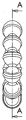
도1은 본 발명의 몇몇 실시예에 따른 복수개의 연결된 커넥터의 측면도를 도시한다.1 illustrates a side view of a plurality of connected connectors in accordance with some embodiments of the present invention.
도2는 본 발명의 몇몇 실시예에 따른 복수개의 연결된 커넥터의 단부도를 도시한다.2 shows an end view of a plurality of connected connectors in accordance with some embodiments of the present invention.
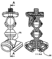
도3은 본 발명의 몇몇 실시예에 따른 복수개의 연결된 커넥터의 단면도이다.3 is a cross-sectional view of a plurality of connected connectors in accordance with some embodiments of the present invention.
도4는 본 발명의 몇몇 실시예에 따른 커넥터의 측면도를 도시이다.4 illustrates a side view of a connector in accordance with some embodiments of the present invention.
도5는 본 발명의 몇몇 실시예에 따른 커넥터의 단면도이다.5 is a cross-sectional view of a connector in accordance with some embodiments of the present invention.
도6은 본 발명의 몇몇 실시예에 따른 파지부를 갖는 커넥터를 도시한다.6 illustrates a connector with a gripping portion in accordance with some embodiments of the present invention.
도7은 본 발명의 몇몇 실시예에 따른 파지부를 갖는 커넥터의 측면도이다.7 is a side view of a connector having a gripping portion in accordance with some embodiments of the present invention.
도8은 본 발명의 몇몇 실시예에 따른 파지부를 갖는 커넥터의 단면도이다.8 is a cross-sectional view of a connector with a gripping portion in accordance with some embodiments of the present invention.
도9는 본 발명의 몇몇 실시예에 따른 트라이포드 장치의 도면이다.9 is a diagram of a tripod device, in accordance with some embodiments of the present invention.
도10은 본 발명의 몇몇 실시예에 따른 트라이포드 장치의 본체 및 상호 연결부의 도면이다.10 is a diagram of a body and interconnects of a tripod device in accordance with some embodiments of the present invention.
도11은 본 발명의 몇몇 실시예에 따른 트라이포드 장치의 본체 및 상호 연결부의 단면도이다.11 is a cross-sectional view of a body and interconnects of a tripod device in accordance with some embodiments of the present invention.
도12는 본 발명의 몇몇 실시예에 따른 트라이포드 장치의 도면이다.12 is a diagram of a tripod device, in accordance with some embodiments of the present invention.
도13은 본 발명의 몇몇 실시예에 따른 트라이포드 장치의 본체 및 상호 연결부의 측단면도이다.Figure 13 is a side cross-sectional view of a body and interconnects of a tripod device in accordance with some embodiments of the present invention.
도14는 본 발명의 몇몇 실시예에 따른 트라이포드 장치의 본체 및 상호 연결부의 측단면도이다.14 is a side cross-sectional view of a body and interconnects of a tripod device in accordance with some embodiments of the present invention.
도15는 본 발명의 몇몇 실시예에 따른 트라이포드 장치의 본체 및 상호 연결부의 측단면도이다.Figure 15 is a side cross-sectional view of a body and interconnects of a tripod device in accordance with some embodiments of the present invention.
도1, 도2 및 도3은 본 발명의 몇몇 실시예에 따른 복수개의 볼 및 소켓 조인트 커넥터(101)를 도시한다. 커넥터(101)는 제1 단부 부분(102) 및 제2 단부 부분(103)을 갖는다. 소켓 결합 단부면(104)은 제1 단부 부분(102)에 존재한다. 제1 단부 부분(102)은 실질적으로 중공형이다.1, 2 and 3 illustrate a plurality of ball and socket
제2 단부 부분(103)은 내부 소켓 수용 공동(107)을 갖는 본체(106)를 갖는다. 내부 소켓 수용 공동(107)의 내부면(110)은 다른 커넥터(101)의 소켓 결합 단부면(104) 또는 유사한 소켓 결합 단부면을 갖는 다른 편에 끼워지도록 구성된다. 네크다운부(neckdown)(105)는 제1 단부 부분(102)을 제2 단부 부분(103)으로부터 분리한다. 멈춤 너브(108)는 볼 및 소켓 조인트 커넥터 쌍의 가능한 우연한 분리 및 각상(angulation)을 방지하는 기계적 멈춤부로서 작동한다.The
도4 및 도5에 도시된 바와 같이, 커넥터(101)는 몇몇 실시예에서 주 축(111)을 갖는다. 커넥터(101)는 몇몇 실시예에서 주 축(111)에 대해 대칭일 수도 있다. 커넥터의 제1 단부 부분 및 제2 단부 부분의 단부면 평면들은 몇몇 실시예에서 주 축(111)에 수직일 수도 있다.As shown in Figures 4 and 5, the
본 발명의 몇몇 실시예에서, 내부 소켓 수용 공동 또는 소켓 결합 단부면, 또는 이들 양자 모두의 벽 두께는 볼 및 소켓 조인트 커넥터가 연결된 후에 억지 끼움(interference fit)이 유지되도록 구성된다. 몇몇 실시예에서, 억지 끼움은 재료가 소성 한계의 응력 레벨보다 낮지만 크리프 한계보다 높은 응력 레벨로 응력을 받는다. 그 후, 재료는 통상적으로 재료의 탄성 변형 응력 범위의 상단 아래로, 억지 끼움(interference)이 크리프 한계에 있거나 크리프 한계보다 낮게 있을 때까지 크리프(creep)할 수 있다. 보다 긴 체인을 형성하도록 함께 연결되는 복수개의 커넥터를 사용하는 이러한 실시예에서, 응력은 상이한 커넥터 쌍들에서 동등해지려는 경향이 있을 것이다. 이러한 응력의 동등화는 다양한 커넥터 쌍들의 마찰을 동등하게 하려는 경향이 있을 것이다. 연결된 커넥터들의 긴 체인에서의 커넥터 쌍들에서의 마찰의 동등화는 체인이 만곡 힘을 받을 때 커넥터들의 체인이 원활한 방식으로 만곡되게 하는 경향이 있을 것이다. 예컨대, 45도 각도로 만곡된 10 유닛 체인에서는 만곡부가 커넥터 쌍들 중에서 완전히 펼쳐질 수도 있다.In some embodiments of the invention, the wall thickness of the inner socket receiving cavity or socket mating end face, or both, is configured such that an interference fit is maintained after the ball and socket joint connectors are connected. In some embodiments, the interference fit is stressed to a stress level at which the material is below the stress level of the plastic limit but above the creep limit. The material may then creep below the top of the elastic strain stress range of the material, until the interference is at or below the creep limit. In this embodiment using a plurality of connectors connected together to form a longer chain, the stress will tend to be equal in different connector pairs. This equalization of stress will tend to equalize the friction of the various connector pairs. Equalization of friction in connector pairs in long chains of connected connectors will tend to cause the chain of connectors to bend in a smooth manner when the chain is subjected to a bending force. For example, in a 10 unit chain that is bent at a 45 degree angle, the bend may be fully extended among the connector pairs.
몇몇 실시예에서, 도6, 도7 및 도8에 도시된 바와 같이, 커넥터(120)는 파지부(122)를 포함한다. 커넥터(120)는 제1 단부 부분(125) 및 제2 단부 부분(123)을 갖는다. 소켓 결합 단부면(124)은 제1 단부(125)에 존재한다. 제1 단부 부 분(125)은 실질적으로 중공형이다.In some embodiments, as shown in FIGS. 6, 7, and 8, the
제2 단부 부분(123)은 내부 소켓 수용 공동(130)을 갖는 본체(121)를 갖는다. 내부 소켓 수용 공동(130)의 내부면(129)은 다른 커넥터의 소켓 결합 단부면(124) 또는 유사한 소켓 결합 단부면을 갖는 다른 편에 끼워지도록 구성된다. 네크다운부(128)는 제1 단부 부분(125)을 제2 단부 부분(123)로부터 분리한다. 파지부(122)는 커넥터가 더욱 용이하게 표면들을 파지하게 한다. 몇몇 실시예에서, 파지부는 커넥터 본체로 공동 성형된다(co-molded). 몇몇 실시예에서, 파지부는 고무 처리된 화합물(rubberized compound)이다. 몇몇 실시예에서, 파지부는 커넥터의 외부면으로 성형되는 주연 링이다. 파지부는 커넥터가 물체 상에 설치되거나 물체 주위를 감쌀(wrap) 때 더 높은 마찰 인터페이스를 제공할 수도 있다.The
본 발명의 몇몇 실시예에서, 소켓 결합 단부면(104)의 외부면(109)이 윤활될 수도 있다. 소켓 결합 단부면(104)의 외부면(109)의 윤활은 커넥터들의 체인에서 다양한 연결부들 사이에 더욱 균일한 마찰을 허용할 수도 있다. 몇몇 실시예에서, 내부 소켓 수용 공동(107)의 내부면(110)은 윤활될 수도 있다. 내부 소켓 수용 공동(107)의 내부면(110)의 윤활은 더욱 균일한 마찰을 허용할 수도 있다. 몇몇 실시예에서, 소켓 결합 단부면(104)의 외부면(109) 및 내부 소켓 수용 공동(107)의 내부면(110) 양자 모두가 윤활될 수도 있다. 몇몇 실시예에서, 면들에는 접착제가 도포될 수도 있다. 아세틸 재료, 델린(Delrin) 및 나일론과 같은 몇몇 커넥터 재료를 사용하여, 접착제로 통상 사용되는 화합물이 억지 끼움되는 볼 및 소켓 조인트 커넥터에 사용될 때 윤활제로서 기능할 수도 있다.In some embodiments of the invention, the
본 발명의 몇몇 실시예에서, 소켓 결합 단부면(104)의 외부면(109)은 텍스처 가공(textured)될 수도 있다. 텍스처 가공(texture)은 표면 거칠기의 형태를 취할 수도 있다. 소켓 결합 단부면(104)의 외부면(109)의 텍스처 가공은 커넥터들의 체인에서의 다양한 연결부 사이의 더욱 균일한 마찰을 허용할 수도 있다. 몇몇 실시예에서, 내부 소켓 수용 공동(107)의 내부면(110)은 텍스처 가공될 수도 있다. 텍스처 가공은 표면 거칠기의 형태를 취할 수도 있다. 내부 소켓 수용 공동(107)의 내부면(110)의 텍스처 가공은 더욱 균일한 마찰을 허용할 수도 있다. 몇몇 실시예에서, 소켓 결합 단부면(104)의 외부면(109) 및 내부 소켓 수용 공동(107)의 내부면(110)은 윤활될 수도 있다.In some embodiments of the present invention, the
도3은 복수개의 볼 및 소켓 조인트 커넥터의 단면도를 도시한다. 본 발명의 몇몇 실시예에서, 멈춤 너브(108)가 내부 소켓 수용 공동 내에 존재한다. 소켓 결합 단부면(104)의 내부 림(140)은 2개의 커넥터들이 서로에 대해 일정 각도에 도달함에 따라 멈춤 너브(108)와 접촉하도록 구성된다. 멈춤 너브(108)와 소켓 결합 단부면(104)의 내부 림(140)의 접촉은 서로에 대해 2개의 편들의 추가 각상에 대한 기계적 멈춤부로서 기능한다. 기계적 멈춤 기능은 2개의 커넥터들의 가능한 연결 해제 및 과회전(over-rotate)을 방지하도록 작용한다.3 illustrates a cross-sectional view of a plurality of ball and socket joint connectors. In some embodiments of the invention, a
도9는 본 발명의 몇몇 실시예에 따른 트라이포드 장치(200)를 도시한다. 본체부(201)는 3개의 가요성 레그부(202, 203, 204)에 지지 기부를 제공한다. 가요성 레그부(202, 203, 204)는 일련의 상호연결된 볼 및 소켓 조인트 커넥터로 구성된다. 가요성 레그부는 다양한 위치로 굽혀질 수도 있고, 트라이포드 지지부를 형 성함으로써 본체부(201)를 지지하는데 이용될 수 있다. 가요성 레그부는 트라이포드가 다양한 상황에서 기능하게 하도록 평탄하지 않은 표면들에 적응할 수 있다. 여기에서 3개의 레그부가 도시되기 위해 사용되었지만, 몇몇 실시예에서는 더 많은 레그부가 존재할 수도 있다. 도9에 도시된 바와 같이, 본체부(201) 자체는 그 내부에 일련의 상호연결된 볼 및 소켓 조인트 커넥터를 가져서, 그의 장착 기능에 있어서 더욱 가요성을 갖는다.9 illustrates a
가요성 레그부는 도7에서 기능 레그부로 도시되지만, 레그부는 충분히 가요성이 있어서, 통상의 트라이포트를 장착하는데 적절하지 않은 물체에 트라이포드 장치를 체결하기 위해 바(bar)와 같은 제품 또는 다른 물체 주위를 감싸는데 이용될 수도 있다. 파지부와 관련하여, 이는 트라이포드 장치가 다양한 물체에 체결되게 한다. 예컨대, 디지털 카메라를 위치시키는데 사용될 때, 레그부는 수직 게이트 레일 주위를 감쌀 수 있어서, 이전에 얻을 수 없는 사진 촬영 기회를 위한 카메라 장착을 허용한다.Although the flexible leg portion is shown as a functional leg portion in FIG. 7, the leg portion is sufficiently flexible such that a product or other object, such as a bar, is used to fasten the tripod device to an object not suitable for mounting a conventional triport. It can also be used to wrap around. With regard to the gripping portion, this allows the tripod device to be fastened to various objects. For example, when used to position a digital camera, the leg portion may wrap around a vertical gate rail, allowing camera mounting for previously unobtainable photography opportunities.
몇몇 실시예에서, 본체부(201)는 상호연결부(205)에 연결된다. 클립(220)은 상호연결부(205)에 제거가능하게 체결된다. 클립(220)은 몇몇 실시예에서 카메라 또는 다른 장치 내로 끼워지도록 구성되는 나사 형성된 포스트를 가질 수도 있다.In some embodiments,
몇몇 실시예에서, 가요성 레그부(202, 203, 204)는 공동 성형된 파지부(208)를 갖는 커넥터를 사용할 수도 있다. 파지부(208)는 포스트 또는 다른 물체 주위에 레그부를 감싸는 것을 포함하는 다양한 방식으로 트라이포드를 사용하는 것을 허용할 수도 있다. 몇몇 실시예에서, 가요성 레그부는 파지 포드(207)로 종단 접 속될 수도 있다. 도3의 단면에 도시된 바와 같이, 파지 포드(pod)(207)는 커넥터의 공동으로 완전히 성형될 수도 있다. 몇몇 실시예에서, 각 레그부의 말단 커넥터는 제1 단부 상의 소켓 결합 단부면과, 제2 단부 상의 흡입 컵을 갖는다. 흡입 컵은 다양한 표면들에 대한 트라이포드 장치(200)의 견고한 부착을 허용할 수도 있다.In some embodiments,
본 발명의 몇몇 실시예에서, 도9, 도10 및 도11에 추가로 도시된 바와 같이, 상호연결부(205)는 클립(220)을 수용하도록 구성된다. 클립(220)은 상호연결부(205) 내의 슬롯(227) 내로 활주하도록 구성된 레일(228)을 가질 수도 있다. 클립(220)은 스프링 장착된 레버(222) 상의 탭(225)에 의해 채워지도록 구성된 리세스(226)를 가질 수도 있다. 클립은 상호연결부(205)에 제거가능하게 부착되고, 레버(222)를 가압함으로써 해제될 수도 있다. 몇몇 실시예에서, 레버(222)는 클립(220)이 활주하는 측부와 동일한 상호연결부(205)의 측부에 있다. 다른 실시예에서, 레버(222)는 클립(220)이 활주하는 측부에 대향하는 측부에 있다.In some embodiments of the present invention, as further shown in FIGS. 9, 10, and 11,
장착 스크류(221)는 몇몇 실시예에서 클립(220) 내에 장착되는 리세스일 수도 있다. 스크류(223)는 몇몇 실시예에서 카메라에 부착하도록 표준 치수로 결정되고 나사 형성될 수도 있다. 스크류(221)의 헤드(223)는 몇몇 실시예에서 리세스의 성형 시에 약간의 리지(slight ridge)에 의해 리세스(224) 내로 보유될 수도 있다.Mounting
본 발명의 몇몇 실시예에서, 도12, 도13, 도14 및 도15에 도시된 바와 같이, 트라이포드 장치(500)가 상이한 구성으로 장치의 레그부를 이격시키고 위치시키는 본체부(501)를 사용한다. 본체 소켓(502)을 이격시키는 것은 몇몇 사용 시에 부착 아암으로서의 트라이포드 레그부를 더 많은 사용하는 것을 허용한다. 몇몇 실시예에서, 본체 소켓(502)은 본체부(501)의 중심 주위에 동등하게 이격된다. 또한, 본체 소켓은 (통상적인 이용 시에) 지면에 대해 각도로 확개된다. 몇몇 실시예에서, 확개된 각도는 45도이다. 본체 소켓을 확개시키는 것은 트라이포드의 레그부에 대한 가능한 래핑(wrapping) 각도의 상이한 범위를 허용한다.In some embodiments of the invention, as shown in FIGS. 12, 13, 14, and 15, the
본체 소켓을 확개함으로써, 트라이포드 레그부는 통상적인 트라이포드의 경우에서와 같이 여전히 사용될 수도 있다. 레그부를 형성하는 커넥터 및 본체 소켓의 운동 범위는 레그부의 수직 위치설정을 허용한다. 따라서, 본체부(501)는 트라이포드의 일반적인 기능성을 보유한다. 그러나, 확개는 수직 바 등 주위를 감쌀 때와 같이 레그부가 파지 아암으로 사용되는 경우에 레그부의 보다 큰 만곡을 허용한다. 따라서, 본체부(501)는 위치 범위 및 장치를 즐기는 용도 유형에 부가된다.By expanding the body socket, the tripod leg portion may still be used as in the case of a conventional tripod. The range of motion of the connector and the body socket forming the leg portion allows vertical positioning of the leg portion. Thus, the
상기 설명으로부터 명백한 바와 같이, 충분히 다양한 실시예들이 본 명세서에 주어진 설명으로부터 구성될 수도 있고, 부가적인 이점 및 변형이 당해 기술분야의 지식을 가진 자에게 용이하게 얻어질 것이다. 따라서, 더 넓은 태양에서의 본 발명은 도시되고 설명된 예시적인 일례들 및 특정한 상세한 설명에 제한되지 않는다. 이에 따라, 이러한 상세한 설명으로부터의 시도는 출원인의 일반적인 발명의 기술사상 또는 범주로부터 벗어나지 않으면서 이루어질 수도 있다.As will be apparent from the above description, a sufficiently wide variety of embodiments may be constructed from the description given herein, and additional advantages and modifications will be readily apparent to those skilled in the art. Thus, the invention in its broader aspects is not limited to the example details and specific details shown and described. Accordingly, attempts from this detailed description may be made without departing from the spirit or scope of the applicant's general invention.
Claims (16)
Applications Claiming Priority (2)
| Application Number | Priority Date | Filing Date | Title |
|---|---|---|---|
| US11/324,994 | 2006-01-03 | ||
| US11/324,994 US20070154254A1 (en) | 2006-01-03 | 2006-01-03 | Mounting apparatus using ball and socket joints with gripping features |
Publications (1)
| Publication Number | Publication Date |
|---|---|
| KR20090016441A true KR20090016441A (en) | 2009-02-13 |
Family
ID=38224571
Family Applications (1)
| Application Number | Title | Priority Date | Filing Date |
|---|---|---|---|
| KR1020087019034A KR20090016441A (en) | 2006-01-03 | 2006-06-06 | Mounting apparatus using ball and socket joints with gripping features |
Country Status (10)
| Country | Link |
|---|---|
| US (5) | US20070154254A1 (en) |
| EP (1) | EP1969244B8 (en) |
| JP (1) | JP5031769B2 (en) |
| KR (1) | KR20090016441A (en) |
| CN (1) | CN101194127B (en) |
| AU (1) | AU2006335293A1 (en) |
| CA (1) | CA2649539C (en) |
| DE (1) | DE202006021110U1 (en) |
| TW (1) | TW200804712A (en) |
| WO (1) | WO2007081388A2 (en) |
Families Citing this family (99)
| Publication number | Priority date | Publication date | Assignee | Title |
|---|---|---|---|---|
| US20070154254A1 (en) * | 2006-01-03 | 2007-07-05 | Bevirt Joeben | Mounting apparatus using ball and socket joints with gripping features |
| US20080056808A1 (en) * | 2006-01-03 | 2008-03-06 | Bevirt Joeben | Monopod mounting apparatus |
| US20100308198A1 (en) * | 2006-01-03 | 2010-12-09 | Bevirt Joeben | Mounting Apparatus Using Flexible Joints With Magnetic Atachment |
| US8297566B2 (en) * | 2006-01-03 | 2012-10-30 | Day Men US, Inc | Mounting apparatus using ball and socket joints with composite connectors |
| US8251536B2 (en) * | 2006-01-03 | 2012-08-28 | Daymen Us, Inc. | Flashlight with mounting apparatus |
| US20070152117A1 (en) * | 2006-01-04 | 2007-07-05 | Byrd Randel L | Viscoelastic Mounting Device |
| US20080265111A1 (en) * | 2007-04-27 | 2008-10-30 | Tocad America, Inc. | Apparatuses and systems for supporting and positioning cameras and other equipment |
| US20080283697A1 (en) * | 2007-04-27 | 2008-11-20 | Richard Darrow | Apparatuses and systems for supporting and positioning cameras and other equipment |
| US20090039213A1 (en) * | 2007-04-27 | 2009-02-12 | Richard Darrow | Apparatuses and systems for supporting and positioning cameras and other equipment |
| US8197149B2 (en) * | 2007-04-27 | 2012-06-12 | Tocad America, Inc. | Apparatuses and systems for supporting and positioning cameras and other equipment |
| CN101644296B (en) * | 2008-08-08 | 2012-01-25 | 鸿富锦精密工业(深圳)有限公司 | Connection unit and ball joints thereof |
| US8087836B2 (en) * | 2008-12-15 | 2012-01-03 | Joby Photo, Inc. | Miniature mounting apparatus |
| US20100221062A1 (en) * | 2008-12-29 | 2010-09-02 | Bevirt Joeben | Ball and Socket Connectors With Substructure |
| WO2010122553A1 (en) * | 2009-04-21 | 2010-10-28 | Aspect Magnet Technologies Ltd. | Flexible segmented support structure |
| US20100294908A1 (en) * | 2009-05-21 | 2010-11-25 | Patrick Mish | BOOKSTAND FOR AN eREADER |
| CN101988615B (en) * | 2009-08-05 | 2012-08-08 | 宁波伟峰影像设备集团有限公司 | Reelable tripod |
| US20110042530A1 (en) * | 2009-08-19 | 2011-02-24 | Mark Phillips | Flexipod with flexible bendable legs with a gripping surface |
| US20120288268A1 (en) * | 2009-12-15 | 2012-11-15 | Bevirt Joeben | Miniature Mounting Apparatus |
| BR112012024359A2 (en) | 2010-03-25 | 2016-05-24 | Nokia Corp | contortion of an electronic device |
| EP2572260B1 (en) | 2010-05-21 | 2019-12-04 | Nokia Technologies Oy | A method, an apparatus and a computer program for controlling an output from a display of an apparatus |
| US20120019113A1 (en) * | 2010-07-26 | 2012-01-26 | Hale Eric C | Device Case and Mounting Apparatus With Flexible Support Legs |
| WO2012094069A2 (en) * | 2011-01-06 | 2012-07-12 | Barnard Brandon | Electronic device holder |
| US8678677B2 (en) * | 2011-05-13 | 2014-03-25 | Cinetics of Texas, LLC | Systems and methods for adapting a mounting device to facilitate capturing of images |
| US9004799B1 (en) * | 2011-08-31 | 2015-04-14 | Skylar Tibbits | Transformable linked self-assembly system |
| CN103062589A (en) * | 2011-10-21 | 2013-04-24 | 鸿富锦精密工业(深圳)有限公司 | Supporting device |
| US8620152B1 (en) | 2011-11-09 | 2013-12-31 | Rex Martin | Auxiliary lens positioning system for portable cameras |
| US8827760B2 (en) | 2011-11-28 | 2014-09-09 | Carrie Park Ushibo | Peripheral apparatus for positioning and using a portable electronic device |
| US20150351531A1 (en) * | 2011-12-21 | 2015-12-10 | Michael T. Dalton | Smartphone or tablet mounting device and method |
| US9823707B2 (en) | 2012-01-25 | 2017-11-21 | Nokia Technologies Oy | Contortion of an electronic apparatus |
| US9823696B2 (en) | 2012-04-27 | 2017-11-21 | Nokia Technologies Oy | Limiting movement |
| US9232966B2 (en) * | 2012-09-24 | 2016-01-12 | Refai Technologies, Llc | Articulating spinal rod system |
| US10016793B2 (en) | 2012-09-28 | 2018-07-10 | Thomas Engineering Solutions & Consulting, Llc | Enhanced knuckle-jointed lance useful for internal cleaning and inspection of tubulars |
| US9158332B2 (en) * | 2012-10-22 | 2015-10-13 | Nokia Technologies Oy | Limiting movement |
| US9158334B2 (en) | 2012-10-22 | 2015-10-13 | Nokia Technologies Oy | Electronic device controlled by flexing |
| TW201420933A (en) * | 2012-11-23 | 2014-06-01 | Wang xin yi | Assembling device with connection component |
| US9517351B2 (en) | 2014-05-17 | 2016-12-13 | Thyne Global, Inc. | Methods and apparatuses for amplitude-modulated ensemble waveforms for neurostimulation |
| US9440070B2 (en) | 2012-11-26 | 2016-09-13 | Thyne Global, Inc. | Wearable transdermal electrical stimulation devices and methods of using them |
| US10814131B2 (en) | 2012-11-26 | 2020-10-27 | Thync Global, Inc. | Apparatuses and methods for neuromodulation |
| US9399126B2 (en) | 2014-02-27 | 2016-07-26 | Thync Global, Inc. | Methods for user control of neurostimulation to modify a cognitive state |
| US11033731B2 (en) | 2015-05-29 | 2021-06-15 | Thync Global, Inc. | Methods and apparatuses for transdermal electrical stimulation |
| US10537703B2 (en) | 2012-11-26 | 2020-01-21 | Thync Global, Inc. | Systems and methods for transdermal electrical stimulation to improve sleep |
| US9448588B2 (en) | 2012-12-12 | 2016-09-20 | Brandon Barnard | Electronic device holder |
| WO2014145323A1 (en) * | 2013-03-15 | 2014-09-18 | Cam Caddie | Camera mounting device |
| JP6410369B2 (en) | 2013-06-29 | 2018-10-24 | セレヴァスト メディカル インク.Cerevast Medical Inc. | Transcutaneous electrical stimulation device for correcting or inducing cognitive state |
| US10293161B2 (en) | 2013-06-29 | 2019-05-21 | Thync Global, Inc. | Apparatuses and methods for transdermal electrical stimulation of nerves to modify or induce a cognitive state |
| US8857775B1 (en) | 2013-07-22 | 2014-10-14 | Gopro, Inc. | Camera mount with spring clamp |
| GB2517495B (en) * | 2013-08-23 | 2015-10-21 | Daren O'sullivan | A flexible securer |
| US9333334B2 (en) | 2014-05-25 | 2016-05-10 | Thync, Inc. | Methods for attaching and wearing a neurostimulator |
| KR20170063440A (en) | 2014-05-25 | 2017-06-08 | 하이인 에쿼티 인베스트먼트 펀드 엘.피. | Wearable transdermal neurostimulators |
| US9511395B2 (en) * | 2014-06-17 | 2016-12-06 | Thomas Engineering Solutions & Consulting, Llc | Knuckle-jointed lance segments with an exterior protective system |
| US9661197B2 (en) * | 2014-10-22 | 2017-05-23 | Gopro, Inc. | Quick-release ball-and-socket joint camera mount |
| CN107002936A (en) * | 2014-11-13 | 2017-08-01 | 科努有限公司 | Portable rack suitable for electronic equipment |
| US11534608B2 (en) | 2015-01-04 | 2022-12-27 | Ist, Llc | Methods and apparatuses for transdermal stimulation of the outer ear |
| WO2016109851A1 (en) | 2015-01-04 | 2016-07-07 | Thync, Inc. | Methods and apparatuses for transdermal stimulation of the outer ear |
| US9874305B2 (en) | 2015-02-18 | 2018-01-23 | OctoGrip, LLC | Multi-appendage device for holding, gripping, or suspending an object |
| DE102016002298A1 (en) | 2015-03-06 | 2016-09-08 | Shimano Inc. | Electric bicycle rear derailleur |
| USD758474S1 (en) | 2015-05-07 | 2016-06-07 | Gopro, Inc. | Camera mount |
| WO2016196635A2 (en) | 2015-06-01 | 2016-12-08 | Cerevast Medical Inc. | Apparatuses and methods for neuromodulation |
| US20170059088A1 (en) * | 2015-09-01 | 2017-03-02 | Marlon Galvez | Personal viewing of a mobile device system and method |
| WO2017106411A1 (en) | 2015-12-15 | 2017-06-22 | Cerevast Medical, Inc. | Electrodes having surface exclusions |
| WO2017106878A1 (en) | 2015-12-18 | 2017-06-22 | Thync Global, Inc. | Apparatuses and methods for transdermal electrical stimulation of nerves to modify or induce a cognitive state |
| US9956405B2 (en) | 2015-12-18 | 2018-05-01 | Thyne Global, Inc. | Transdermal electrical stimulation at the neck to induce neuromodulation |
| GB2548684A (en) * | 2016-02-05 | 2017-09-27 | Gripple Ltd | Support device for supporting a first article on a second article |
| US10646708B2 (en) | 2016-05-20 | 2020-05-12 | Thync Global, Inc. | Transdermal electrical stimulation at the neck |
| US9891509B2 (en) | 2016-06-17 | 2018-02-13 | Mimono LLC | Projector holder |
| USD782464S1 (en) | 2016-06-20 | 2017-03-28 | Paul J. Chung | Mobile device accessory with flexible neck |
| KR102582394B1 (en) | 2016-08-30 | 2023-09-26 | 삼성디스플레이 주식회사 | Semiconductor device |
| CN106287146A (en) * | 2016-10-19 | 2017-01-04 | 成都尚智恒达科技有限公司 | A kind of electronic product movable landing bracing frame of lift adjustable-angle |
| DE102016224806A1 (en) * | 2016-12-13 | 2018-06-14 | Hansgrohe Se | fastening system |
| GB2558935B (en) * | 2017-01-20 | 2020-01-29 | Sbfi Ltd | Improvements in display screen mounting |
| USD840464S1 (en) * | 2017-02-13 | 2019-02-12 | Vitec Holdings Italia Srl | Adjustable tripod |
| USD839339S1 (en) * | 2017-03-14 | 2019-01-29 | Vitec Holdings Italia Srl | Adjustable tripod |
| US10595471B2 (en) * | 2017-03-24 | 2020-03-24 | Ian Gilley | System and methods for directing plant growth |
| US11081309B2 (en) | 2017-04-21 | 2021-08-03 | Unger Marketing International, Llc | Light bulb removing and installing assemblies |
| USD840209S1 (en) | 2017-04-21 | 2019-02-12 | Unger Marketing International, Llc | Handle |
| USD864694S1 (en) | 2017-04-21 | 2019-10-29 | Unger Marketing International, Llc | Handle |
| USD843435S1 (en) * | 2017-05-16 | 2019-03-19 | Vitec Holdings Italia Srl | Pan and tilt body with device mounting clamp on a tripod |
| USD834105S1 (en) | 2017-06-01 | 2018-11-20 | Mattel-Mega Holdings (Us), Llc | Construction set element |
| USD870799S1 (en) | 2017-06-06 | 2019-12-24 | Arlo Technologies, Inc. | Flexible camera mount |
| USD829806S1 (en) * | 2017-07-21 | 2018-10-02 | Vitec Holdings Italia Srl | Mounting ring with extensions |
| USD829807S1 (en) * | 2017-07-21 | 2018-10-02 | Vitec Holdings Italia Srl | Mounting ring with extensions on a tripod |
| GB2565322B (en) | 2017-08-10 | 2021-12-01 | Atelier Volant Llc | Coupling for linkages |
| JP6512388B1 (en) | 2017-10-19 | 2019-05-15 | 日本精工株式会社 | Telescopic link and suspension |
| US10568419B2 (en) * | 2017-11-09 | 2020-02-25 | Ppj, Llc | Room caddie |
| USD872167S1 (en) * | 2017-12-12 | 2020-01-07 | Vitec Holdings Italia Srl | Tripod with clamp and extensions |
| WO2018127888A2 (en) * | 2018-04-13 | 2018-07-12 | Instituto Panameño De Derecho Y Nuevas Tecnologías (Ipandetec) | Device as a demountable stand for photo cameras |
| US11278724B2 (en) | 2018-04-24 | 2022-03-22 | Thync Global, Inc. | Streamlined and pre-set neuromodulators |
| WO2020033389A1 (en) | 2018-08-07 | 2020-02-13 | Gopro, Inc. | Camera and camera mount |
| USD894256S1 (en) | 2018-08-31 | 2020-08-25 | Gopro, Inc. | Camera mount |
| USD905786S1 (en) | 2018-08-31 | 2020-12-22 | Gopro, Inc. | Camera mount |
| US10718997B2 (en) * | 2019-01-17 | 2020-07-21 | John Kiernan-Lewis | Modular tripod-arm |
| US11090189B2 (en) * | 2019-02-06 | 2021-08-17 | Earl Kelly | Eye drop alignment assembly |
| USD921095S1 (en) | 2019-06-19 | 2021-06-01 | Gopro, Inc. | Camera mount |
| USD920419S1 (en) | 2019-09-17 | 2021-05-25 | Gopro, Inc. | Camera |
| US20210262611A1 (en) * | 2020-02-24 | 2021-08-26 | Onyekachi Eke-Okoro | Apparatus and Methods using hollow figures for storing edible products at a portable electronic device |
| USD946074S1 (en) | 2020-08-14 | 2022-03-15 | Gopro, Inc. | Camera |
| USD989847S1 (en) * | 2020-11-24 | 2023-06-20 | Ningbo Yizhou Machinery Co., Ltd. | Tripod |
| CN112696579B (en) * | 2020-12-30 | 2022-05-27 | 天津市泛亚工程咨询有限公司 | Building engineering cost on-site mapping device based on BIM technology |
| CN114321579A (en) * | 2021-11-16 | 2022-04-12 | 南通佰瑞利电动工具有限公司 | A universal regulation cloud platform of spirit level for vaulting pole support |
Family Cites Families (74)
| Publication number | Priority date | Publication date | Assignee | Title |
|---|---|---|---|---|
| DE854100C (en) * | 1943-03-06 | 1952-10-30 | Ludwig Dipl-Ing Dr-Ing Grassl | Flexible bracket |
| US2684822A (en) * | 1948-10-02 | 1954-07-27 | Eugene A Odin | Supporting structure |
| FR1098836A (en) * | 1954-03-31 | 1955-08-22 | Semi-flexible tube | |
| US2824503A (en) | 1954-09-10 | 1958-02-25 | Rollei Werke Franke Heidecke | Quick attachable mounting for photographic cameras |
| US3006052A (en) | 1959-01-13 | 1961-10-31 | Donald B Stickney | Instrument attaching device |
| US3306634A (en) * | 1963-02-07 | 1967-02-28 | Pul Vac Inc | Articulate joint |
| US3329967A (en) * | 1965-03-31 | 1967-07-11 | Henry J Martinez | Diving suit |
| US3356325A (en) | 1965-10-22 | 1967-12-05 | Davidson Optronics Inc | Camera-to-tripod connector |
| US3612462A (en) | 1969-08-26 | 1971-10-12 | Quick Set Inc | Instrument mount assembly |
| US4016583A (en) * | 1975-06-24 | 1977-04-05 | Yeates Calvin B | Camera steadying device |
| US4057816A (en) | 1976-01-13 | 1977-11-08 | Polaroid Corporation | Accessory adapter |
| US4085915A (en) * | 1977-01-11 | 1978-04-25 | Kyong Jin Song | Coupling device for equipping a camera onto the tripod |
| JPS54160147U (en) * | 1978-04-28 | 1979-11-08 | ||
| DE3011798A1 (en) * | 1980-03-27 | 1981-10-01 | Norbert Dipl.-Ing. 6000 Frankfurt Schiller | Camera or microphone stand - has legs of flexible material with lower end eyelets for securing chain |
| CH646762A5 (en) * | 1980-06-06 | 1984-12-14 | Ferag Ag | BALL JOINT LINK CHAIN. |
| US4525052A (en) * | 1983-01-27 | 1985-06-25 | Slik Tripod Co., Ltd. | Device for fixing a camera to a tripod |
| US4570887A (en) | 1983-10-17 | 1986-02-18 | Banister Gerald K | Quick-connect mount for a camera and tripod |
| US4536116A (en) * | 1983-11-07 | 1985-08-20 | Maclean-Fogg Company | Composite molded plastic article |
| US4739801A (en) * | 1985-04-09 | 1988-04-26 | Tysubakimoto Chain Co. | Flexible supporting sheath for cables and the like |
| JPS61197395U (en) * | 1985-05-30 | 1986-12-09 | ||
| JPS6240397U (en) * | 1985-08-30 | 1987-03-10 | ||
| JPS63106993U (en) * | 1986-12-27 | 1988-07-11 | ||
| JPH01125435U (en) | 1988-02-16 | 1989-08-28 | ||
| JPH0626799Y2 (en) | 1989-02-28 | 1994-07-20 | 平和精機工業株式会社 | Pan head |
| JPH03129333A (en) * | 1989-10-14 | 1991-06-03 | Konica Corp | Camera tripod |
| JP2502358Y2 (en) * | 1989-12-13 | 1996-06-19 | ヤンマー農機株式会社 | Rear safety device for speed sprayer |
| JPH05145816A (en) | 1991-11-18 | 1993-06-11 | Sony Corp | Video camera system |
| US5276596A (en) * | 1992-06-23 | 1994-01-04 | Krenzel Ronald L | Holder for a flashlight |
| USRE38897E1 (en) * | 1992-06-23 | 2005-11-29 | Elward-Louis Joint Venture | Wrappable flashlight |
| US5398176A (en) * | 1993-04-19 | 1995-03-14 | Ahuja; Sushil K. | Multifunctional lamp and support |
| US5449206A (en) * | 1994-01-04 | 1995-09-12 | Lockwood Products, Inc. | Ball and socket joint with internal stop |
| FR2714863B1 (en) * | 1994-01-11 | 1996-03-29 | Facom | Tool handle. |
| US5655736A (en) * | 1994-06-30 | 1997-08-12 | Kozloff; Matthew S. | Retaining device for an electronic signalling device |
| DE9411987U1 (en) | 1994-07-23 | 1994-09-29 | Novoflex Fotogeraetebau Karl M | Device for releasably connecting a photographic or optical device to a tripod or the like. |
| US5517392A (en) * | 1994-08-05 | 1996-05-14 | Black & Decker Inc. | Sleeve retention for flexible core of a flashlight |
| JP2691869B2 (en) * | 1994-09-22 | 1997-12-17 | ハクバ写真産業株式会社 | Portable tripod |
| US5851036A (en) * | 1995-12-14 | 1998-12-22 | Vanesky; Frank W. | Permanent fitting for fluid-tight connections |
| US5997047A (en) * | 1996-02-28 | 1999-12-07 | Pimentel; Ralph | High-pressure flexible self-supportive piping assembly |
| US5647565A (en) * | 1996-03-07 | 1997-07-15 | Wei; David | Tripod |
| US5620352A (en) * | 1996-03-29 | 1997-04-15 | Tzong; Chun-Chuen | Flexible tube having a number of joints |
| KR19990067074A (en) * | 1996-08-27 | 1999-08-16 | 겐고 호리우치 | Camera support |
| JP3083135B2 (en) * | 1996-08-27 | 2000-09-04 | 健吾 堀内 | Camera support leg |
| US5857241A (en) * | 1997-02-19 | 1999-01-12 | The Wooster Brush Company | Soft grip handle |
| US6196504B1 (en) * | 1998-07-09 | 2001-03-06 | Maurice W. Lemke | Positive-lock-and-release device for camera mounting |
| JP2000056391A (en) | 1998-07-31 | 2000-02-25 | Kanji Tomidokoro | Tripod head system for camera |
| US6173725B1 (en) * | 1999-01-19 | 2001-01-16 | Geoffrey C. Garth | Canopy structure |
| US6988846B2 (en) * | 1999-10-18 | 2006-01-24 | Philippe Vogt | Device for attaching a retaining member for an optical apparatus to a support |
| US6352227B1 (en) * | 2000-06-08 | 2002-03-05 | Clarence Eduard Hathaway | Segmented, ball jointed support |
| US6408524B1 (en) * | 2000-06-16 | 2002-06-25 | Yin-Chu Lai | Tableware grip structure with comfortable touch feeling |
| US6626210B2 (en) * | 2001-01-12 | 2003-09-30 | Water Pik, Inc. | Flexible arm assembly |
| US20030066937A1 (en) * | 2001-10-09 | 2003-04-10 | Nathan Smith | Remote control support assembly |
| US7035092B2 (en) * | 2001-11-08 | 2006-04-25 | Apple Computer, Inc. | Computer controlled display device |
| US6672788B2 (en) * | 2002-02-04 | 2004-01-06 | Clarence Eduard Hathaway | Ball joint with detent action |
| US6648376B2 (en) * | 2002-03-29 | 2003-11-18 | Showertek, Inc. | Flexible sectioned arm with internal overbending-prevention sleeves |
| DE10238706A1 (en) * | 2002-08-23 | 2004-03-11 | Pöhlmann, Werner, Dr.jur. | Camera and stand have housing joined together by adhesive arrangement, with interlinked legs |
| DE20213278U1 (en) * | 2002-08-26 | 2002-12-19 | Schrader Peter | Device for holding a camera assembly on a harness |
| JP3825753B2 (en) * | 2003-01-14 | 2006-09-27 | 株式会社東芝 | Manufacturing method of semiconductor device |
| US6767153B1 (en) * | 2003-02-10 | 2004-07-27 | Dana W. Holbrook | Locking positional arm device |
| JP2004317578A (en) | 2003-04-11 | 2004-11-11 | Fujicolor Imaging Service Co Ltd | Tripod for portable telephone with camera |
| US20040211868A1 (en) | 2003-04-24 | 2004-10-28 | Holmes Joseph T. | Webcam mount for flexible positioning |
| US6729778B1 (en) * | 2003-06-24 | 2004-05-04 | Shing Ming Wu | Fixture for fixing camera and the likes capable of adjusting the pitching angle of the camera |
| US7533906B2 (en) * | 2003-10-14 | 2009-05-19 | Water Pik, Inc. | Rotatable and pivotable connector |
| WO2005073032A1 (en) * | 2004-01-27 | 2005-08-11 | Joy Gregory T | Portable tripod and universal mounting assembly for an object |
| JP2005260522A (en) | 2004-03-11 | 2005-09-22 | Brother Ind Ltd | Image inputting device |
| US20050205730A1 (en) * | 2004-03-17 | 2005-09-22 | Carnevali Jeffrey D | Configurable mounting bracket |
| US7344320B2 (en) * | 2004-03-17 | 2008-03-18 | Trek Technologies, Llc | Walking staff with tripod base and adaptable mount |
| KR101109583B1 (en) * | 2004-11-04 | 2012-01-31 | 삼성전자주식회사 | Imaging apparatus having open/close holder part |
| US20060175482A1 (en) | 2005-01-06 | 2006-08-10 | Joseph Johnson | Tripod head |
| US7563038B2 (en) | 2005-06-20 | 2009-07-21 | Lino Manfrotto + Co. S.P.A. | Support for a camcorder |
| US7185862B1 (en) * | 2005-10-04 | 2007-03-06 | Jen Yu Yang | Mounting platform assembly for a stand device |
| US8297566B2 (en) * | 2006-01-03 | 2012-10-30 | Day Men US, Inc | Mounting apparatus using ball and socket joints with composite connectors |
| US20070154254A1 (en) * | 2006-01-03 | 2007-07-05 | Bevirt Joeben | Mounting apparatus using ball and socket joints with gripping features |
| US20080265111A1 (en) * | 2007-04-27 | 2008-10-30 | Tocad America, Inc. | Apparatuses and systems for supporting and positioning cameras and other equipment |
| US20080283697A1 (en) * | 2007-04-27 | 2008-11-20 | Richard Darrow | Apparatuses and systems for supporting and positioning cameras and other equipment |
-
2006
- 2006-01-03 US US11/324,994 patent/US20070154254A1/en not_active Abandoned
- 2006-06-06 WO PCT/US2006/021703 patent/WO2007081388A2/en active Application Filing
- 2006-06-06 CN CN2006800148816A patent/CN101194127B/en not_active Expired - Fee Related
- 2006-06-06 KR KR1020087019034A patent/KR20090016441A/en not_active Application Discontinuation
- 2006-06-06 JP JP2008548496A patent/JP5031769B2/en not_active Expired - Fee Related
- 2006-06-06 EP EP06772124A patent/EP1969244B8/en active Active
- 2006-06-06 CA CA2649539A patent/CA2649539C/en active Active
- 2006-06-06 AU AU2006335293A patent/AU2006335293A1/en not_active Abandoned
- 2006-06-06 DE DE202006021110U patent/DE202006021110U1/en not_active Expired - Lifetime
- 2006-07-04 TW TW095124320A patent/TW200804712A/en unknown
-
2007
- 2007-05-09 US US11/801,234 patent/US7891615B2/en active Active - Reinstated
- 2007-09-14 US US11/901,254 patent/US20080069630A1/en not_active Abandoned
-
2011
- 2011-01-14 US US13/006,434 patent/US8740160B2/en active Active - Reinstated
-
2014
- 2014-06-02 US US14/293,671 patent/US20160053935A1/en not_active Abandoned
Also Published As
| Publication number | Publication date |
|---|---|
| EP1969244B8 (en) | 2012-10-03 |
| JP2009522516A (en) | 2009-06-11 |
| US8740160B2 (en) | 2014-06-03 |
| US20080069630A1 (en) | 2008-03-20 |
| CN101194127B (en) | 2013-03-27 |
| JP5031769B2 (en) | 2012-09-26 |
| US20160053935A1 (en) | 2016-02-25 |
| CN101194127A (en) | 2008-06-04 |
| TW200804712A (en) | 2008-01-16 |
| DE202006021110U1 (en) | 2012-09-06 |
| EP1969244A2 (en) | 2008-09-17 |
| US20110108683A1 (en) | 2011-05-12 |
| CA2649539A1 (en) | 2007-07-19 |
| US20070154254A1 (en) | 2007-07-05 |
| US20070212163A1 (en) | 2007-09-13 |
| AU2006335293A1 (en) | 2007-07-19 |
| EP1969244A4 (en) | 2010-07-21 |
| WO2007081388A2 (en) | 2007-07-19 |
| US7891615B2 (en) | 2011-02-22 |
| WO2007081388A3 (en) | 2007-11-01 |
| CA2649539C (en) | 2014-10-07 |
| EP1969244B1 (en) | 2012-08-29 |
Similar Documents
| Publication | Publication Date | Title |
|---|---|---|
| KR20090016441A (en) | Mounting apparatus using ball and socket joints with gripping features | |
| US8366341B2 (en) | Attachment clips for support structures | |
| CN101542142B (en) | Mounting appratus using ball and socket joints with composite connectors | |
| US8087836B2 (en) | Miniature mounting apparatus | |
| US20080217493A1 (en) | Suction cup for rough surfaces | |
| US20080056808A1 (en) | Monopod mounting apparatus | |
| US8696153B2 (en) | Flashlight with mounting apparatus | |
| JP2009522516A5 (en) | ||
| US20100264281A1 (en) | Gripping Clip and Mounting Apparatus Using Same | |
| US20120288268A1 (en) | Miniature Mounting Apparatus | |
| US20100308198A1 (en) | Mounting Apparatus Using Flexible Joints With Magnetic Atachment | |
| US20100221062A1 (en) | Ball and Socket Connectors With Substructure |
Legal Events
| Date | Code | Title | Description |
|---|---|---|---|
| A201 | Request for examination | ||
| E902 | Notification of reason for refusal | ||
| E601 | Decision to refuse application | ||
| J201 | Request for trial against refusal decision | ||
| J501 | Disposition of invalidation of trial |