JP5014207B2 - Engine balancer equipment - Google Patents
Engine balancer equipment Download PDFInfo
- Publication number
- JP5014207B2 JP5014207B2 JP2008063059A JP2008063059A JP5014207B2 JP 5014207 B2 JP5014207 B2 JP 5014207B2 JP 2008063059 A JP2008063059 A JP 2008063059A JP 2008063059 A JP2008063059 A JP 2008063059A JP 5014207 B2 JP5014207 B2 JP 5014207B2
- Authority
- JP
- Japan
- Prior art keywords
- balancer
- pair
- housing
- engine
- thrust
- Prior art date
- Legal status (The legal status is an assumption and is not a legal conclusion. Google has not performed a legal analysis and makes no representation as to the accuracy of the status listed.)
- Expired - Fee Related
Links
Images


Landscapes
- Cylinder Crankcases Of Internal Combustion Engines (AREA)
Description
本発明は、エンジン下部のオイルパン内に収容され、クランク軸によって駆動されるエンジンのバランサ装置に関する。 The present invention relates to an engine balancer device housed in an oil pan below an engine and driven by a crankshaft.
従来より、この種のバランサ装置としては、例えばオイルパン内にバランサ軸を剥き出し状態で支持するタイプが知られている(特許文献1)。ところが、このタイプではバランス軸がオイルに浸かるため、回転時にオイルとの間で回転抵抗が発生する問題や、攪拌によってオイルの酸化劣化を助長する問題などがあった。 Conventionally, as this type of balancer device, for example, a type that supports a balancer shaft in an exposed state in an oil pan is known (Patent Document 1). However, in this type, since the balance shaft is immersed in the oil, there is a problem that rotational resistance is generated between the oil and the oil at the time of rotation, and a problem that promotes oxidation deterioration of the oil by stirring.
そこで、上面が開放された略半円筒形状のバランサ軸ホルダを有し、これに一対のバランサ軸を受容して、バランサ軸がオイルに浸からないようにしたつりあい装置(バランサ装置)も提案されている(特許文献2)。 In view of this, there has also been proposed a balancing device (balancer device) which has a balancer shaft holder having a substantially semi-cylindrical shape with an open upper surface and which receives a pair of balancer shafts so that the balancer shaft is not immersed in oil. (Patent Document 2).
また、上記特許文献1、2には、バランサ軸のスラスト変位を規制するスラストプレートが開示されている。特許文献1のスラストプレートはバランサーホルダー(軸支持部材)の一側面にボルトで固定され、特許文献2のスラストプレートはバランサ軸ホルダの後端にボルトで固定されている。
しかしながら、いずれのスラストプレートもバランサ軸の一方から加わるスラスト力だけを受け止めるように構成されているため、他方からもスラスト力が加わるような場合には対応できない。 However, since any of the thrust plates is configured to receive only the thrust force applied from one of the balancer shafts, it cannot cope with the case where the thrust force is applied from the other.
両方から加わるスラスト力を規制するために、例えば、上記スラストプレートと対向するように別途スラストプレートを追加して設けることも考えられるが、部材や工数が倍増する不利がある。 In order to restrict the thrust force applied from both, for example, a separate thrust plate may be provided so as to face the thrust plate, but there is a disadvantage that the number of members and man-hours is doubled.
本発明はかかる点に鑑みてなされたものであり、その主たる目的とするところは、簡単な構成でありながらバランサ軸の両方から加わるスラスト力を規制することができ、コンパクトで取り扱いに優れたバランサ装置を提供することにある。 The present invention has been made in view of the above points, and the main object of the present invention is to provide a compact balancer that is capable of regulating the thrust force applied from both of the balancer shafts while having a simple configuration, and that is compact and excellent in handling. To provide an apparatus.
上記目的を達成するために、本発明では、バランサハウジングを複数の部材で構成し、その構成部材である軸支持部材とハウジング本体部材との間に、各バランサ軸のスラスト規制溝に嵌装可能な板状のスラストプレートを配置した。 In order to achieve the above object, according to the present invention, the balancer housing is composed of a plurality of members, and can be fitted into the thrust restricting grooves of each balancer shaft between the shaft support member and the housing body member, which are the component members. A plate-shaped thrust plate was placed.
具体的には、エンジンの下部に、クランク軸と平行な方向である前後方向に延びるように一対のバランサ軸を配置して、バランサハウジングに収容してなるバランサ装置であって、上記バランサハウジングは、上記一対のバランサ軸をそれぞれ回転自在に支持する前後一対の軸支持部材と、これら軸支持部材の間に配置されるハウジング本体部材と、いずれか一方の軸支持部材とハウジング本体部材との間に配置される板状のスラストプレートと、を有している。 Specifically, the balancer device is configured by disposing a pair of balancer shafts in the lower part of the engine so as to extend in the front-rear direction, which is parallel to the crankshaft, and accommodated in the balancer housing. A pair of front and rear shaft support members that rotatably support the pair of balancer shafts, a housing body member disposed between the shaft support members, and between any one of the shaft support members and the housing body member And a plate-like thrust plate disposed on the plate.
上記一対の各バランサ軸の外周には、全周にわたってスラスト規制溝が形成されている一方、上記スラストプレートには、上部が開放された一対のスラスト規制孔が貫通形成されていて、これら各スラスト規制孔の周縁部が、各バランサ軸のスラスト規制溝に擦動自在に嵌装されている構成とする。 On the outer periphery of each of the pair of balancer shafts, a thrust restricting groove is formed over the entire circumference, while the thrust plate is formed with a pair of thrust restricting holes that are open at the top. The periphery of the restriction hole is configured to be slidably fitted into the thrust restriction groove of each balancer shaft.
この構成によれば、まず、一対のバランサ軸は、バランサハウジングに収容されているので、オイルパン内に配設されてもそこに溜まるオイルから隔離することができ、従来のバランサ装置のような回転抵抗等の問題を解消することができる。 According to this configuration, since the pair of balancer shafts are accommodated in the balancer housing, the balancer shaft can be isolated from the oil accumulated in the oil pan even if disposed in the oil pan. Problems such as rotational resistance can be solved.
そして、板状のスラストプレートに形成されたスラスト規制孔の周縁部が各バランサ軸のスラスト規制溝に擦動自在に嵌装されているので、バランサ軸の両方から加わるスラスト力は、一枚のスラストプレートに受け止められて規制される。 And since the peripheral portion of the thrust restricting hole formed in the plate-like thrust plate is slidably fitted in the thrust restricting groove of each balancer shaft, the thrust force applied from both balancer shafts is It is received by the thrust plate and regulated.
また、各スラスト規制孔はその上部が開放されているので、そこから各バランサ軸をスラスト規制孔内に受け入れることができ、バランサ軸を軸支持部材やハウジング本体部材に仮組みした後からでもスラストプレートを組み付けることができる。 Also, since each thrust restricting hole is open at the top, each balancer shaft can be received in the thrust restricting hole from there, and even after the balancer shaft is temporarily assembled to the shaft support member or the housing body member, the thrust restricting hole can be received. Plates can be assembled.
上記バランサハウジングは、その上面に開口部を形成し、その開口部を上方から覆うようにハウジングカバーを設け、ハウジング本体部材の左右の端部とハウジングカバーの左右の端部との間に隙間があくようにしておくとよい。 The balancer housing has an opening formed on the upper surface thereof, a housing cover is provided so as to cover the opening from above, and there is a gap between the left and right ends of the housing body member and the left and right ends of the housing cover. It is good to keep it open.
そうすれば、まず、開口部の形成によってバランサハウジングの軽量化を図ることができる。そして、その開口部の上方はハウジングカバーで覆われているので、上方からのバランサハウジング内部への不用意なオイルの浸入は防がれる。さらに、ハウジング本体部材の左右の端部とハウジングカバーの左右の端部との間に隙間があいているので、そこからバランサハウジング内のオイルを外部に排出させることが可能になる。 If it does so, first, weight reduction of a balancer housing can be achieved by formation of an opening part. Since the upper portion of the opening is covered with the housing cover, inadvertent oil intrusion into the balancer housing from above is prevented. Further, since there is a gap between the left and right ends of the housing body member and the left and right ends of the housing cover, the oil in the balancer housing can be discharged from there.
更に、上記ハウジングカバーによってスラストプレートの上方が覆われていると、スラストプレートの上方からバランサハウジング内へ不用意にオイルが浸入するのを抑制できる。 Furthermore, if the upper portion of the thrust plate is covered by the housing cover, it is possible to prevent oil from inadvertently entering the balancer housing from above the thrust plate.
また、更にハウジング本体部材の前後方向の寸法よりも長く形成された支持ボルトを有するとともに、上記一対の軸支持部材、ハウジング本体部材及びスラストプレートにそれぞれ前後方向に延びる挿通孔を設け、これら挿通孔に上記支持ボルトを挿通して、上記一対の軸支持部材、ハウジング本体部材及びスラストプレートを締結するようにしてもよい。 The housing body member further includes a support bolt formed longer than the longitudinal dimension of the housing body member, and the pair of shaft support members, the housing body member, and the thrust plate are provided with insertion holes extending in the longitudinal direction, respectively. The pair of shaft support members, the housing body member, and the thrust plate may be fastened by inserting the support bolts.
そうすれば、バランサ軸と平行に、比較的長寸のボルトで各軸支持部材等が一体に締結されるため、その締結力がバランサハウジング全体に作用してバランスよく固定できるとともに、強固に固定してもバランサ軸の軸線方向に作用するだけであるからバランサ軸とこれを支持する各軸支持部材との同軸度にずれを招くおそれがない。 Then, each shaft support member is fastened together with relatively long bolts in parallel with the balancer shaft, so that the fastening force acts on the entire balancer housing and can be fixed in a well-balanced manner, and firmly fixed. However, since it only acts in the axial direction of the balancer shaft, there is no possibility of causing a shift in the coaxiality between the balancer shaft and each shaft support member that supports the balancer shaft.
上記一対のバランサ軸は、それぞれ転がり軸受を介して支持するようにすれば、メタル軸受に比べて回転抵抗を大きく低減することができる。 If the pair of balancer shafts are supported via rolling bearings, the rotational resistance can be greatly reduced as compared with the metal bearing.
その場合、上記一対の各バランサ軸が、各々転がり軸受を介して支持される前後一対のジャーナル部と、これら両ジャーナル部間に設けられる相対的に大径の主バランスウエイト部と、各ジャーナル部の前側、後側にそれぞれ設けられる相対的に小径の一対のバランスウエイト固定部と、を有するものとし、上記各転がり軸受に挿通されて前後に突出する上記一対のバランスウエイト固定部のそれぞれに、偏心部材を組み付けて副バランスウエイト部を構成するとよい。 In that case, each of the pair of balancer shafts is supported by a pair of front and rear journal parts supported via rolling bearings, a relatively large-diameter main balance weight part provided between the two journal parts, and each journal part. A pair of relatively small-diameter balance weight fixing portions provided respectively on the front side and the rear side of each of the pair of balance weight fixing portions that are inserted through the respective rolling bearings and protrude forward and backward. A sub-balance weight portion may be configured by assembling an eccentric member.
そうすれば、各ジャーナル部を挟んだバランサ軸の軸線方向における各ジャーナルのウエイトバランスが良くなるため、転がり軸受に加わる曲げ負荷を低減させることができる。更に、バランスウエイト部をバランサ軸の軸線方向に分散配置することで、つりあい性能はそのままにして相対的にバランスウエイト部の外径寸法を小さくできるため、軸間距離を小さくできてバランサハウジングがコンパクトになる。 If it does so, since the weight balance of each journal in the axial direction of the balancer axis | shaft which pinched | interposed each journal part will become good, the bending load added to a rolling bearing can be reduced. Furthermore, by distributing the balance weight in the axial direction of the balancer shaft, the outer diameter of the balance weight can be made relatively small while maintaining the balance performance, so the distance between the shafts can be reduced and the balancer housing is compact. become.
また、バランサ軸をバランサユニットに組み付ける際には、ジャーナル部よりも小径のバランサウエイト固定部を転がり軸受に挿通した後、そこに偏心部材を組み付けて副バランスウエイト部を構成することができるので、転がり軸受の内径及びジャーナル部の外径を副バランスウエイト部の外径よりも小さくでき、軸支持部材やバランサ軸が小さくなってバランサハウジングがコンパクトになる。 Also, when assembling the balancer shaft to the balancer unit, the balancer weight fixing part having a smaller diameter than the journal part can be inserted into the rolling bearing, and then an eccentric member can be assembled there to constitute the sub balance weight part. The inner diameter of the rolling bearing and the outer diameter of the journal portion can be made smaller than the outer diameter of the auxiliary balance weight portion, and the shaft support member and the balancer shaft become smaller, and the balancer housing becomes compact.
以上説明したように、本発明のバランサ装置によれば、一枚のスラストプレートでバランサ軸の両方から加わるスラスト力を規制することができる。また、バランサ装置の組み付け時には、バランサハウジングに一対のバランサ軸を仮組みしてから、スラストプレートを組み付けることができるため、作業性に優れる。装置全体がコンパクトにまとめられてユニット化されているため、取り扱いに優れ、オイルパン内に配設しても邪魔にならないし、バランサ軸もオイルに浸からずに済む。 As described above, according to the balancer device of the present invention, the thrust force applied from both of the balancer shafts can be regulated by a single thrust plate. Further, when assembling the balancer device, since the thrust plate can be assembled after the pair of balancer shafts are temporarily assembled to the balancer housing, the workability is excellent. Since the entire apparatus is compact and unitized, it is easy to handle, and even if it is placed in an oil pan, it does not get in the way and the balancer shaft does not need to be immersed in oil.
以下、本発明の実施形態を図面に基づいて詳細に説明する。尚、以下の好ましい実施形態の説明は、本質的に例示に過ぎず、本発明、その適用物或いはその用途を制限することを意図するものではない。 Hereinafter, embodiments of the present invention will be described in detail with reference to the drawings. It should be noted that the following description of the preferred embodiment is merely illustrative in nature, and is not intended to limit the present invention, its application, or its use.
図1は、本発明のバランサ装置を装着した直列4気筒エンジンであり、その要部をエンジン本体1の前方から見た概略図を示している。同図において、エンジン本体1の下部を構成するロアブロック1aの下面にオイルパン2が接合されていて、そのロアブロック1aからオイルパン2にかけて当該バランサ装置Bが収容されている。
FIG. 1 is an in-line four-cylinder engine equipped with a balancer device of the present invention, and shows a schematic view of the main part viewed from the front of an
バランサ装置Bは、伝動機構を介してクランク軸1bで駆動されるようになっており、その伝動機構は、クランク軸1bに固定された駆動側スプロケット1cや、これよりも大径の被駆動側スプロケット3、これらに巻き掛けられるチェーン4、チェーン4のテンションを調整するテンショナー5などで構成されている。
The balancer device B is driven by a
エンジン本体1は、同図に示す鉛直線Sに対して幾分傾いた状態で車両に搭載され、その状況下でオイルパン2の内部に貯留されるオイルは、レベル面Lがロアブロック1aとの接合面に対して傾斜した状態でその略下半分の空間を満たしている。
The
そして、そのオイルのレベル面Lよりも上方に位置するように、つまり、オイルに浸かることがないようにバランサ装置Bはコンパクトに構成されていて、オイルパン2の上方に張り付くように設置される。尚、バランサ装置Bの一部がオイルに浸かるようにオイルのレベル面Lが設定されることを妨げるものではない。
And the balancer apparatus B is comprised compactly so that it may be located above the level surface L of the oil, ie, it may not be immersed in oil, and it is installed so that it may stick to the upper part of the
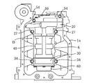
図2は、そのバランサ装置Bの全体を示している。同図に示すように、バランサ装置Bは、一つのユニットとして構成されており、複数の部材を組み合わせて一体化したバランサハウジング6と、その内部に収容されてエンジンの前後方向に(クランク軸1bと平行に)延びる一対のバランサ軸7,7とを備えている。
FIG. 2 shows the entire balancer apparatus B. As shown in the figure, the balancer device B is configured as a single unit, and is a
(バランサハウジング)
バランサハウジング6は、図2に示すように、アルミダイキャスト品である、前軸支持部材20及び後軸支持部材30、これら前後一対の軸支持部材20,30の間に配置されるハウジング本体部材40、これら軸支持部材20,30に各々装着される前カバー部材50及び後カバー部材60などで構成されている。
(Balancer housing)
As shown in FIG. 2, the
前軸支持部材20は、図3に示すように、前後方向に延びるブロック状の支持部本体21と、この支持部本体21の前端縁から側方及び下方に張り出し形成されたフランジ壁22とを有し、このフランジ壁22を前方に向けた状態でバランサ軸7の前端部分を受け入れるように配設される。
As shown in FIG. 3, the front
詳しくは、支持部本体21には、その前後方向に延びるように、一対のバランサ軸7,7を回転自在に支持する2つの軸受孔23,23が左右方向に隣接して貫通形成されている。ここでは図示しないが、各軸受孔23には、ニードルローラベアリング(転がり軸受)8が挿嵌される(例えば図8参照)。各軸受孔23の前側にはこれらに連続して、後述する第1入力ギヤ77等が収容される空間(入力室24)が形成されている(例えば図8参照)。
Specifically, the support portion
また、これら2つの軸受孔23,23を間に挟む、支持部本体21の上部の左右2箇所と、各軸受孔23,23の間の下側1箇所には、後述する支持ボルト9を挿通するために、前後方向に延びるボルト挿通孔25,25,25が貫通形成されている。更に、支持部本体21の左右両端部からは、外方に張出ボス部26,26が張り出しており、これら張出ボス部26,26には上下方向に貫通する取付孔27がそれぞれ形成されている。支持部本体21の前端面には前カバー部材50と接合するために、そして、後端面にはハウジング本体部材40と接合するために面一状の接合部が形成されている。
Also,
ハウジング本体部材40は、図4に示すように、前後方向に延びる底壁41と、この底壁41の左右から屈曲して立ち上がる円弧状の左右の側壁42,42とを有し、その前端面には前軸支持部材20と接合するために、そして、その後端面には後述するスラストプレート80が介在した状態で後軸支持部材30と接合するために面一状の接合部が形成されている。そうして、ハウジング本体部材40の前後両端面に各軸支持部材20,30が接合されると、バランサハウジング6の上面には、大きく開口する開口部45が形成される(図6参照)。
As shown in FIG. 4, the
ハウジング本体部材40の内部には、後述する各バランサ軸7,7の主バランスウエイト部71,71を収容する主バランスウエイト収容部43と、これの後側に連続して連動ギヤ74,74を収容するキヤ収容部44とが設けられている。
Inside the
支持ボルト9を受け入れるために、左右の側壁42,42の上部にはそれぞれ前後方向に延びるボルト挿通孔47,47が形成されているとともに、底壁41の内面の左右方向の中間部位には前後方向に延びるボルト溝48が凹み形成されている。
In order to receive the
ハウジング本体部材40の左右の側壁42,42の上端には、その前後方向の中間部位から両壁42,42間に跨る補強用のブリッジ46が一体に形成されている。また、左右の側壁42,42の各上端面の前後及び中間の3箇所には、ハウジングカバー90を締結するためのボス部49,49,49がそれぞれ突設されている。
On the upper ends of the left and
このハウジングカバー90は、鋼板のプレス加工品からなり、図2に示すように、バランサハウジング6の上部に形成される開口部45を上方から覆うように、先のハウジング本体部材40の左右側壁に突設されたボス部49,・・・にボルトで締結される。このように、バランサハウジング6の上面に開口部45を形成してハウジングカバー90で覆うようにすることで、バランサハウジング6の軽量化及び材料コストの削減が実現されている。ハウジングカバー90の後端部には、ギヤ収容部44に臨むオイル供給用の開口91が形成されている。尚、ハウジング本体部材40及びハウジングカバー90の細部については後述する。
The
後軸支持部材30は、図4に示すように、前軸支持部材20の支持部本体21と似た形状のブロック体からなる。すなわち、後軸支持部材30には、その前後方向に延びるように、一対のバランサ軸7,7を回転自在に支持する2つの軸受孔31,31が左右方向に隣接して貫通形成されており、これら軸受孔31,31にはニードルローラベアリング8,8が挿嵌される(例えば図8参照)。
As shown in FIG. 4, the rear
そして、後軸支持部材30の上部のこれら2つの軸受孔31,31を間に挟む左右2箇所と、各軸受孔31,31の間の下側1箇所には、支持ボルト9を挿通するために前後方向に延びるボルト挿通孔32,32,32が貫通形成されている。更に、左右両端部から外方に張り出す張出ボス部33,33には上下方向に貫通する取付孔34がそれぞれ形成されている。後軸支持部材30の前端面にはスラストプレート80を介在させた状態でハウジング本体部材40と接合するために、そして、後端面には後カバー部材60と接合するために面一状の接合部が形成されている。
And in order to insert the
スラストプレート80は、各バランサ軸7のスラスト力を受け止めてその軸線方向の変位を規制するためにハウジング本体部材40と後軸支持部材30との間に嵌装される板状の部材からなる。
The
詳しくは、図4に示すように、スラストプレート80は、耐摩耗性に優れた金属素材からなるプレス加工品であり、ハウジング本体部材40と後軸支持部材30とが接合されるその接合面と略同一の外形形状に加工されている。
Specifically, as shown in FIG. 4, the
スラストプレート80の側面には、一対のスラスト規制孔82,82が左右横並びに形成されている。これらスラスト規制孔82,82は、その上部が開放されるとともに、上下方向に延びる長孔状に形成されていて、一対のバランサ軸7,7を上方から受け入れ可能となっている。
On the side surface of the
スラスト規制孔82は、それぞれ略U字状をしていて、その平行な左右幅寸法はバランサ軸7のジャーナル部70の外径よりも僅かに大きく形成されている。そして、スラスト規制孔82の周縁部が後述するバランサ軸7のスラスト規制溝101に嵌装されて、その半円形状をした下端の部位がバランサ軸7のスラスト変位を規制する規制片部となる。
Each of the
また、スラストプレート80の側面には、これらスラスト規制孔82,82と共に、前軸支持部材20のボルト挿通孔25等が形成された3箇所の部位に対応してボルト挿通孔81,81,81が形成されている。
Further, on the side surface of the
前カバー部材50は、図5に示すように、前軸支持部材20の前面全体を覆うように構成されていて、前カバー部材50で前軸支持部材20の前面を覆うことで後述する第1入力ギヤ77等を収容する入力室24が形成される(例えば図8参照)。また、前カバー部材50の前軸支持部材20に接合される面一状の接合部には、前軸支持部材20のボルト挿通孔25等が形成された3箇所の部位に対応して、前後方向に貫通するボルト挿通孔52,52,52が形成されている。更に、前カバー部材50の左右端部からはそれぞれ張出ボス部53,53が外方に張り出しており、これら張出ボス部53,53には上下方向に貫通する取付孔54がそれぞれ形成されている。
As shown in FIG. 5, the
一方、後カバー部材60は、図2に示すように横長のカップ形状をしていて、一対のバランサ軸7,7の後端部分をまとめて覆うように、後軸支持部材30の後端面に装着される。このように前後の軸支持部材20,30それぞれに前後のカバー部材50,60を装着することにより、前後方向からバランサハウジング6の内部へオイルが浸入するのを阻止している。
On the other hand, the
(バランサハウジングの組み付け)
このような複数の部材が組み合わされるバランサハウジング6は、主として3本の支持ボルト9,9,9の締結によって一体化される。
(Assembly of balancer housing)
The
すなわち、図2や図4に示すように、前カバー部材50、前軸支持部材20、ハウジング本体部材40、スラストプレート80、及び後軸支持部材30の順に各部材を接合して仮組みした状態で、少なくともハウジング本体部材40の前後方向の寸法よりも長い3本の支持ボルト9,9,9を、各部材に形成された挿通孔52,25,47,81,32,・・・及び挿通溝8の3箇所に通してナットで締結する。
That is, as shown in FIG. 2 and FIG. 4, the
3箇所の締結でバランサハウジング6を一体化できることから作業性に優れるのはもちろんのこと、バランサ軸7と平行に、バランサハウジング6を構成する各部材を一まとめに締結できるため、その締結力がバランサハウジング6全体に作用してバランスよく一体化できる。その際、その締結力はバランサ軸7の軸線方向に作用するだけでバランサ軸7と軸受孔23,31との同軸度にずれを招くおそれがないため、安心して確りと締結できる。
Since the
(バランサ軸)
一対のバランサ軸7,7は、図6〜図8に示すように、バランサハウジング6の内部にその前後方向に延びるように配置されていて、エンジン本体1に配設したときには、各バランサ軸7の軸心がクランク軸1bの軸心を通る垂直面に関して同一水平面内で左右対称になるように平行に配置される。
(Balancer shaft)
The pair of
各バランサ軸7には、例えば図7に示すように、その軸線方向に所定間隔をあけて位置する前後一対のジャーナル部70,70と、これら両ジャーナル部70,70間に位置する相対的に大径の主バランスウエイト部71と、各ジャーナル部70の前側、後側にそれぞれ位置する相対的に小径のバランスウエイト固定部72,72とが一体に設けられており、例えば図6の(b)に示すように、抜止部材73や連動ギヤ74、ニードルローラベアリング8、前後一対の偏心マス部材(偏心部材)75,75などが組み付けられている。
For example, as shown in FIG. 7, each
詳しくは、主バランスウエイト部71は、図6や図9に示すように、バランサ軸7の中間部に形成されていて、重心が軸心から偏心した略半円柱形状のマス部71aを有し、その外径はバランサ軸7の他の部分よりも大きくなっている。この主バランスウエイト部71に続く後側には、連動ギヤ74が固定されている。
Specifically, as shown in FIGS. 6 and 9, the main
各連動ギヤ74は、互いに噛み合う同径のヘリカルギヤからなり、その噛み合いによって両バランサ軸7,7は、上記マス部71a,71aが常に同じ高さに位置するように同期して逆向きに回転する。尚、これら連動ギヤ74,74は、ハウジング本体部材40のギヤ収容部44に収容される。
Each interlocking
これら連動ギヤ74,74の噛み合いによって、各バランサ軸7,7には互いに前後逆方向のスラスト力が発生する。
Due to the meshing of these interlocking gears 74, 74, thrust forces are generated on the
連動ギヤ74に続く後側及び主バランスウエイト部71の前側に続くそれぞれの部位には、各々同径のジャーナル部70,70が形成されている。これらジャーナル部70,70は、その外周にニードルローラベアリング8,8が介装された状態で前後の軸受部23,31に支持される。
各連動ギヤ74と各ジャーナル部70との間には、例えば図7や図11に示すように、リング状のスラスト規制環100がバランサ軸7に圧入されて固定されている。
Between each interlocking
スラスト規制環100の前側には、連動ギヤ74の後端面に対向するプレート受面を有する半径方向外側に張り出したプレート規制部100aが形成されており、このプレート規制部100aのプレート受面と連動ギヤ74の後端面との間に、スラストプレート80が嵌装されるスラスト規制溝101が構成されている。
On the front side of the
そして、スラストプレート80に形成されているスラスト規制孔82の周縁部(以下、規制片部ともいう)がこのバランサ軸7の外周に形成されたスラスト規制溝101に嵌装されると、バランサ軸7が前後方向に変位しようとしても、連動ギヤ74の後端面はスラストプレート80の規制片部の前側に接当し、プレート規制部100aのプレート受面はスラストプレート80の規制片部の後側に接当して、バランサ軸7の前後両側から加わるスラスト力によるスラスト変位が規制される。
When the peripheral edge portion of the
尚、ニードルローラベアリング8は、一般に図6や図7等に示すように、構造上半径方向の外寸法がメタル軸受に比べて大きくなる不利があるが、例えば、本実施形態のニードルローラベアリング8が主バランスウエイト部71よりも僅かに大径な程度となっているように、ジャーナル部70を小径に形成したことでコンパクトに収めることが可能になっている。
In general, the
前後の各ジャーナル部70,70に続く前側及び後側の部位には、図7や図8に示すように、それぞれ各ジャーナル部70よりも小径のバランスウエイト固定部72,72が設けられていて、そこに偏心マス部材75,75が回動不能に取り付けらている。偏心マス部材75は、図6の(b)に示すように重心が軸心から偏心した略半円柱形状のマス部75aを有する略円筒体からなる。前側の偏心マス部材75は、後側の偏心マス部材75よりも軸方向に長く形成されている。尚、本実施形態の偏心マス部材75は、主バランスウエイト部71と略同径に形成されているが、これよりも大きくても小さくてもよい。
As shown in FIGS. 7 and 8, balance
ここで、図8ではその上方に位置する一方のバランサ軸7の前側のバランスウエイト固定部72には、更にそこから前方に延びる延伸部76が一体に設けられていて、そこに第1入力ギヤ77が組み付けられるようになっている。この第1入力ギヤ77は、図6の(b)や図7に示すように、これよりも大径の第2入力ギヤ78ととともに先の前軸支持部材20の前側に形成される入力室24内に収容される。
Here, in FIG. 8, the balance
第1入力ギヤ77及び第2入力ギヤ78は、互いに噛み合っていて、第2入力ギヤ78の前カバー部材50の外方に突出する回転軸の一端には、図6に示すように、先の伝動機構を構成するスプロケット3が取り付けられている。そうして、クランク軸1bが回転すると、伝動機構を介して一対のバランサ軸7,7がエンジンの2倍の回転数で回転するように構成されている。また、各バランサ軸7,7の前後両端部には、先の抜止部材73を締結する締結穴79がその軸線方向に延びるように凹設されている。
The
(バランサ軸のバランサハウジングへの組み付け)
このような構成の一対のバランサ軸7,7では、各偏心マス部材75,・・・及び第1入力ギヤ77は後付けされるようになっていて、例えば、ニードルローラベアリング8,・・・が挿嵌された前後の軸受孔23,23,31,31に、その両側のバランスウエイト固定部72,・・・を挿通しながらバランサハウジング6を仮組みする。そして、前後の軸支持部材20,30から前後に突出するバランスウエイト固定部72,・・・や延伸部76に、偏心マス部材75・・・や第1入力ギヤ77を装着して抜止部材73,・・・を締結穴79,・・・に締結する。
(Assembly of balancer shaft to balancer housing)
In the pair of
このとき、図4に示すように、スラストプレート80は、ハウジング本体部材40と後軸支持部材30との間に組み付けられるが、スラストプレート80の各スラスト規制孔82の上部は開放されているので、一対のバランサ軸7,7を収容して先に仮組みしたバランサハウジング6に対し、その下方から差し込んでスラストプレート80を組み付けることができ、その作業の容易化が図られている。
At this time, as shown in FIG. 4, the
すなわち、仮にスラスト規制孔82の一側が開放されていなければ、スラスト規制環100を各バランサ軸7に圧入して固定する前に、スラストプレート80を一対のバランサ軸7,7に装着しておく必要があり、その圧入作業や圧入後の組み付け作業が極めて困難になるからである。
That is, if one side of the
その後は、前述したように3本の支持ボルト9,9,9などを締結し、本締めすれば一体化できる。
Thereafter, as described above, the three
このように、比較的大径の偏心部材75を後付けで組み付けることで、ジャーナル部70の外径が相対的に小さくなってバランサハウジング6がコンパクトになることに加え、ジャーナル部70の両側にバランスウエイト部を分散配置したことで、バランサ軸7の外形が更に小さくなってよりいっそうバランサハウジング6がコンパクトになる。また、ジャーナル部70のウエイトバランスがよくなる結果、メタル軸受よりも曲がり負荷の影響を受け易いニードルローラベアリング8を採用できるようになる。
In this way, by attaching the
(バランサ装置の装着)
こうして一体に構成されたバランサ装置Bは、図10に示すように、ロアブロック1aの下部にボルト止めすることにより組み付けられる。
(Install balancer device)
As shown in FIG. 10, the balancer device B configured integrally in this way is assembled by bolting to the lower part of the lower block 1 a.
詳しくは、前軸支持部材20、後軸支持部材30及び前カバー部材50の左右の張出ボス部26,33,53の各々6箇所に形成された取付孔27,34,54,・・・に対応して、ロアブロック1aの下面に締結孔が6箇所開口している(図示せず)。ロアブロック1aの下面の所定位置にバランサ装置Bを配置して、これら締結孔に各取付孔27,34,54,・・・に挿通したボルトを締結することにより、バランサ装置Bはエンジン本体1に装着される。
Specifically, the mounting
このように、ボルトを6箇所締結するだけでバランサ装置Bをエンジン本体1に装着できるため、組み付け作業性が向上するし、比較的大きな負荷のかかる前後の軸支持部材20,30が直接ロアブロック1aに締結されるため、確りと固定できる。
Thus, since the balancer device B can be attached to the
こうしてエンジン本体1に装着されたバランサ装置Bは、最初にも説明したように、オイルパン2内の比較的小さなスペースに収まるため、オイルパン2内には十分なスペースが確保でき、例えば、図示しないオイルポンプ等もオイルの貯留スペースを気にせず余裕をもってオイルパン内部に配設することができる。
Since the balancer device B mounted on the engine
また、ハウジング本体部材40はオイルのレベル面Lよりも上方に位置し、バランサハウジング6には、前後のカバー部材50,60やハウジングカバー90が装着されているため、バランサハウジング6内への不用意なオイルの浸入も効果的に阻止できる。
The
更に、本発明のバランサ装置Bは、それに加えて不図示のニードルローラベアリング8への給油や開口91からの給油で、上方からのバランサハウジング6内への不用意なオイルの浸入も阻止できるように工夫されている。
Further, the balancer apparatus B of the present invention can prevent inadvertent intrusion of oil into the
すなわち、先に説明したように、スラストプレート80の各スラスト規制孔82,82の上方は、例えば図7に示すように開放されているため、そこからバランサハウジング6内にオイルが浸入し易くなっている。
That is, as described above, since the upper portions of the
そこで、図11に示すように、ハウジングカバー90は、ハウジング本体部材40を越えてスラストプレート80の上方を覆うように後方に延びていて、その後端部分90aは、スラストプレート80と後軸支持部材30との接合部位よりも更に後方に位置している。つまり、スラストプレート80の上方はハウジングカバー90によって確実に覆われているので、スラストプレート80の開口部分からバランサハウジング6内に不用意にオイルが浸入するのを抑制できる。
Therefore, as shown in FIG. 11, the
また、バランサハウジング6内にオイルが浸入しても、そのオイルは自動的に排出されるようになっている。
Further, even when oil enters the
すなわち、図9に示すように、ハウジングカバー90の左右の端部とハウジング本体部材40の左右の端部との間には、先に説明したボス部49の介在によってハウジングカバー90の前後方向に隙間92,92があいており、その隙間92,92を介してハウジング本体部材40の内部は外部と連通している。一方、ハウジング本体部材40の主バランスウエイト収容部43の内壁面は、バランサ軸7の主バランスウエイト部71の外周の回動軌跡に近接するように円弧状に形成されている。
That is, as shown in FIG. 9, between the left and right end portions of the
各バランサ軸7は、図9の矢印線で示すように、同期して各々その下半周側が内側から外側へ向かうように高速で回転するため、主バランスウエイト収容部43に浸入したオイルは、マス部75aによってハウジングカバー90の左右の両端部に掻き揚げられる。掻き揚げられたオイルは、ハウジングカバー90の両端部の内面に反射して隙間92を通って外部に排出される。つまり、バランサハウジング6内に浸入したオイルはバランサ軸7の回転によって溜まる間もなく排出されることとなる。
Each
以上、説明したように、本発明のバランサ装置Bによれば、板状の一つのスラストプレート80を簡単な作業で組み込むだけでバランサ軸7の両側から加わるスラスト力を規制することができる。バランサ軸7のバランサウエイト部をバランスよく分散配置したことで、従来の装置に比べて装置全体をコンパクトにユニット化することができ、取り扱いに優れ、軸受部への負荷も軽減できる。バランサハウジング6内への不用意なオイルの浸入もよく防ぐことができ、オイルが浸入しても直ぐに排出されて溜まることがないため、回転抵抗等の問題を招かずに済む。
As described above, according to the balancer device B of the present invention, the thrust force applied from both sides of the
なお、本発明にかかるバランサ装置Bは、前記の実施の形態に限定されず、それ以外の種々の構成をも包含する。 The balancer device B according to the present invention is not limited to the above-described embodiment, but includes various other configurations.
すなわち、スラストプレート80は、前軸支持部材20とハウジング本体部材40との間に配置することもできる。転がり軸受に限らず、滑り軸受(メタル軸受等)を採用してもよい。また、転がり軸受は、ニードルローラベアリング8(針状ころ軸受)に限らず、円筒ころ軸受や玉軸受であってもよい。前カバー部材50は支持ボルト9で締結するのではなく、別途装着するようにしてもよい。後付けされる偏心マス部材75や第1入力ギヤ77は、バランサ軸7に着脱不能に取り付けてもよい。さらに、バランサハウジング6は、車両へのエンジン搭載時にオイルのレベル面Lが一部浸かるような高さ関係で配置されていてもよい。
That is, the
1 エンジン本体
1a ロアブロック
1b クランク軸
2 オイルパン
6 バランサハウジング
7 バランサ軸
8 ニードルローラベアリング(転がり軸受)
9 支持ボルト
20 前軸支持部材
23 軸受部
25 ボルト挿通孔(挿通孔)
30 後軸支持部材
31 軸受部
32 ボルト挿通孔(挿通孔)
40 ハウジング本体部材
47 ボルト挿通孔(挿通孔)
50 前カバー部材
52 ボルト挿通孔(挿通孔)
60 後カバー部材
70 ジャーナル部
71 主バランスウエイト部
72 バランスウエイト固定部
75 偏心マス部材(偏心部材)
80 スラストプレート
81 ボルト挿通孔(挿通孔)
82 スラスト規制孔
81 ボルト挿通孔(挿通孔)
90 ハウジングカバー
92 隙間
101 スラスト規制溝
B バランサ装置
1 Engine body
9
30 Rear
40
50
60
80
82
90
Claims (6)
上記バランサハウジングは、上記一対のバランサ軸をそれぞれ回転自在に支持する前後一対の軸支持部材と、これら軸支持部材の間に配置されるハウジング本体部材と、いずれか一方の軸支持部材とハウジング本体部材との間に配置される板状のスラストプレートと、を有し、
上記一対の各バランサ軸の外周には、全周にわたってスラスト規制溝が形成されている一方、上記スラストプレートには、上部が開放された一対のスラスト規制孔が貫通形成されていて、これら各スラスト規制孔の周縁部が、各バランサ軸のスラスト規制溝に擦動自在に嵌装されていることを特徴とするエンジンのバランサ装置。 A balancer device in which a pair of balancer shafts are arranged at the lower part of the engine so as to extend in the front-rear direction, which is parallel to the crankshaft, and housed in a balancer housing,
The balancer housing includes a pair of front and rear shaft support members that rotatably support the pair of balancer shafts, a housing body member disposed between the shaft support members, and any one of the shaft support members and the housing body. A plate-shaped thrust plate disposed between the members,
On the outer periphery of each of the pair of balancer shafts, a thrust restricting groove is formed over the entire circumference, while the thrust plate is formed with a pair of thrust restricting holes that are open at the top. A balancer device for an engine, wherein a peripheral portion of the restriction hole is slidably fitted into a thrust restriction groove of each balancer shaft.
上記バランサハウジングの上面には開口部が形成され、その開口部を上方から覆うようにハウジングカバーが設けられ、
ハウジング本体部材の左右の端部とハウジングカバーの左右の端部との間に隙間があいていることを特徴とするエンジンのバランサ装置。 The engine balancer device according to claim 1,
An opening is formed on the upper surface of the balancer housing, and a housing cover is provided so as to cover the opening from above,
A balancer device for an engine, wherein a gap is provided between left and right ends of the housing body member and left and right ends of the housing cover.
上記ハウジングカバーによってスラストプレートの上方が覆われていることを特徴とするエンジンのバランサ装置。 An engine balancer device according to claim 2,
A balancer device for an engine, characterized in that the upper part of the thrust plate is covered by the housing cover.
更に、ハウジング本体部材の前後方向の寸法よりも長く形成された支持ボルトを有するとともに、上記一対の軸支持部材、ハウジング本体部材及びスラストプレートにそれぞれ前後方向に延びる挿通孔を設け、
これら挿通孔に上記支持ボルトを挿通して、上記一対の軸支持部材、ハウジング本体部材及びスラストプレートが締結されていることを特徴とするエンジンのバランサ装置。 An engine balancer device according to any one of claims 1 to 3,
Furthermore, it has a support bolt formed longer than the dimension in the front-rear direction of the housing body member, and provided with insertion holes extending in the front-rear direction in the pair of shaft support members, the housing body member, and the thrust plate,
An engine balancer device, wherein the support bolt is inserted into the insertion holes, and the pair of shaft support members, the housing body member, and the thrust plate are fastened.
上記一対のバランサ軸が、それぞれ転がり軸受を介して支持されていることを特徴とするエンジンのバランサ装置。 An engine balancer device according to any one of claims 1 to 4,
A balancer device for an engine, wherein the pair of balancer shafts are respectively supported via rolling bearings.
上記一対の各バランサ軸が、各々転がり軸受を介して支持される前後一対のジャーナル部と、これら両ジャーナル部間に設けられる相対的に大径の主バランスウエイト部と、各ジャーナル部の前側、後側にそれぞれ設けられる相対的に小径の一対のバランスウエイト固定部と、を有し、
上記各転がり軸受に挿通されて前後に突出する上記一対のバランスウエイト固定部のそれぞれに、偏心部材が組み付けられて副バランスウエイト部が構成されていることを特徴とするエンジンのバランサ装置。 An engine balancer device according to claim 5,
Each of the pair of balancer shafts is a pair of front and rear journal parts supported via rolling bearings, a relatively large-diameter main balance weight part provided between the two journal parts, the front side of each journal part, A pair of relatively small-diameter balance weight fixing portions respectively provided on the rear side,
An engine balancer device in which an eccentric member is assembled to each of the pair of balance weight fixing portions that are inserted through the respective rolling bearings and protrude forward and backward, to constitute a sub balance weight portion.
Priority Applications (1)
| Application Number | Priority Date | Filing Date | Title |
|---|---|---|---|
| JP2008063059A JP5014207B2 (en) | 2008-03-12 | 2008-03-12 | Engine balancer equipment |
Applications Claiming Priority (1)
| Application Number | Priority Date | Filing Date | Title |
|---|---|---|---|
| JP2008063059A JP5014207B2 (en) | 2008-03-12 | 2008-03-12 | Engine balancer equipment |
Publications (2)
| Publication Number | Publication Date |
|---|---|
| JP2009216224A JP2009216224A (en) | 2009-09-24 |
| JP5014207B2 true JP5014207B2 (en) | 2012-08-29 |
Family
ID=41188281
Family Applications (1)
| Application Number | Title | Priority Date | Filing Date |
|---|---|---|---|
| JP2008063059A Expired - Fee Related JP5014207B2 (en) | 2008-03-12 | 2008-03-12 | Engine balancer equipment |
Country Status (1)
| Country | Link |
|---|---|
| JP (1) | JP5014207B2 (en) |
Cited By (1)
| Publication number | Priority date | Publication date | Assignee | Title |
|---|---|---|---|---|
| CN104999425A (en) * | 2015-08-07 | 2015-10-28 | 广西玉柴机器股份有限公司 | Error-proofing method for engine thrust plate assembly |
Family Cites Families (8)
| Publication number | Priority date | Publication date | Assignee | Title |
|---|---|---|---|---|
| JPS572656Y2 (en) * | 1976-06-11 | 1982-01-18 | ||
| JPS55158339U (en) * | 1979-05-01 | 1980-11-14 | ||
| JPS639796Y2 (en) * | 1980-09-25 | 1988-03-23 | ||
| JPS58112751U (en) * | 1982-01-27 | 1983-08-02 | ヤンマーディーゼル株式会社 | Internal combustion engine balancer shaft support structure |
| JPS58140346U (en) * | 1982-03-17 | 1983-09-21 | ヤンマーディーゼル株式会社 | engine balancer |
| JPS6224153U (en) * | 1985-07-29 | 1987-02-14 | ||
| JPS6384442U (en) * | 1986-11-25 | 1988-06-02 | ||
| JP2786651B2 (en) * | 1989-02-09 | 1998-08-13 | 本田技研工業株式会社 | Thrust bearing structure of balancer shaft |
-
2008
- 2008-03-12 JP JP2008063059A patent/JP5014207B2/en not_active Expired - Fee Related
Cited By (2)
| Publication number | Priority date | Publication date | Assignee | Title |
|---|---|---|---|---|
| CN104999425A (en) * | 2015-08-07 | 2015-10-28 | 广西玉柴机器股份有限公司 | Error-proofing method for engine thrust plate assembly |
| CN104999425B (en) * | 2015-08-07 | 2017-04-05 | 广西玉柴机器股份有限公司 | A kind of method that engine thrust plate assembles mistake proofing |
Also Published As
| Publication number | Publication date |
|---|---|
| JP2009216224A (en) | 2009-09-24 |
Similar Documents
| Publication | Publication Date | Title |
|---|---|---|
| EP0789166B1 (en) | Balance shaft supporting structure in engine | |
| EP1081345B1 (en) | Balance shaft housing | |
| US6471008B1 (en) | Balance shaft housing | |
| US8047176B2 (en) | Balancer apparatus for an engine | |
| JP3875341B2 (en) | Engine with vehicle balancer device | |
| US10731551B2 (en) | Balancer device for internal combustion engine | |
| JP6601147B2 (en) | Engine balancer device and motorcycle | |
| JP5357132B2 (en) | Crankcase integrated balancer device | |
| JP5186424B2 (en) | Engine balancer equipment | |
| JP4947527B2 (en) | Balancer device for internal combustion engine | |
| JP5014207B2 (en) | Engine balancer equipment | |
| JP4789833B2 (en) | engine | |
| US7159558B2 (en) | Engine having centralized mass | |
| US11391341B2 (en) | Balancer device for internal combustion engines | |
| JP2009216225A (en) | Engine balancer device | |
| JP2005061388A (en) | Engine starter | |
| EP1375909A2 (en) | Pinion-shaft support structure for starter in power unit | |
| JP2007009737A (en) | Engine shaft layout structure | |
| JP3730557B2 (en) | Balancer shaft for engine balancing device | |
| JP2006077651A (en) | Engine | |
| WO2021187033A1 (en) | Balancer device and balancer device provided with oil pump | |
| JP2012202442A (en) | Balancer device for internal combustion engine and bearing structure of metal shaft | |
| JP3854450B2 (en) | Engine balancer equipment | |
| JP2003065064A (en) | Parallel four cylinder engine for vehicle | |
| JP5226728B2 (en) | Balancer device for internal combustion engine |
Legal Events
| Date | Code | Title | Description |
|---|---|---|---|
| A621 | Written request for application examination |
Free format text: JAPANESE INTERMEDIATE CODE: A621 Effective date: 20101217 |
|
| A977 | Report on retrieval |
Free format text: JAPANESE INTERMEDIATE CODE: A971007 Effective date: 20111227 |
|
| RD02 | Notification of acceptance of power of attorney |
Free format text: JAPANESE INTERMEDIATE CODE: A7422 Effective date: 20120316 |
|
| A521 | Request for written amendment filed |
Free format text: JAPANESE INTERMEDIATE CODE: A821 Effective date: 20120316 |
|
| TRDD | Decision of grant or rejection written | ||
| A01 | Written decision to grant a patent or to grant a registration (utility model) |
Free format text: JAPANESE INTERMEDIATE CODE: A01 Effective date: 20120508 |
|
| A01 | Written decision to grant a patent or to grant a registration (utility model) |
Free format text: JAPANESE INTERMEDIATE CODE: A01 |
|
| A61 | First payment of annual fees (during grant procedure) |
Free format text: JAPANESE INTERMEDIATE CODE: A61 Effective date: 20120605 |
|
| FPAY | Renewal fee payment (event date is renewal date of database) |
Free format text: PAYMENT UNTIL: 20150615 Year of fee payment: 3 |
|
| R150 | Certificate of patent or registration of utility model |
Ref document number: 5014207 Country of ref document: JP Free format text: JAPANESE INTERMEDIATE CODE: R150 Free format text: JAPANESE INTERMEDIATE CODE: R150 |
|
| R250 | Receipt of annual fees |
Free format text: JAPANESE INTERMEDIATE CODE: R250 |
|
| R250 | Receipt of annual fees |
Free format text: JAPANESE INTERMEDIATE CODE: R250 |
|
| R250 | Receipt of annual fees |
Free format text: JAPANESE INTERMEDIATE CODE: R250 |
|
| S531 | Written request for registration of change of domicile |
Free format text: JAPANESE INTERMEDIATE CODE: R313531 |
|
| S533 | Written request for registration of change of name |
Free format text: JAPANESE INTERMEDIATE CODE: R313533 |
|
| R350 | Written notification of registration of transfer |
Free format text: JAPANESE INTERMEDIATE CODE: R350 |
|
| R250 | Receipt of annual fees |
Free format text: JAPANESE INTERMEDIATE CODE: R250 |
|
| R250 | Receipt of annual fees |
Free format text: JAPANESE INTERMEDIATE CODE: R250 |
|
| R250 | Receipt of annual fees |
Free format text: JAPANESE INTERMEDIATE CODE: R250 |
|
| R250 | Receipt of annual fees |
Free format text: JAPANESE INTERMEDIATE CODE: R250 |
|
| LAPS | Cancellation because of no payment of annual fees |