EP1375909A2 - Pinion-shaft support structure for starter in power unit - Google Patents
Pinion-shaft support structure for starter in power unit Download PDFInfo
- Publication number
- EP1375909A2 EP1375909A2 EP03010409A EP03010409A EP1375909A2 EP 1375909 A2 EP1375909 A2 EP 1375909A2 EP 03010409 A EP03010409 A EP 03010409A EP 03010409 A EP03010409 A EP 03010409A EP 1375909 A2 EP1375909 A2 EP 1375909A2
- Authority
- EP
- European Patent Office
- Prior art keywords
- pinion
- crankcase
- shaft
- transmission
- power unit
- Prior art date
- Legal status (The legal status is an assumption and is not a legal conclusion. Google has not performed a legal analysis and makes no representation as to the accuracy of the status listed.)
- Withdrawn
Links
Images

Classifications
-
- F—MECHANICAL ENGINEERING; LIGHTING; HEATING; WEAPONS; BLASTING
- F02—COMBUSTION ENGINES; HOT-GAS OR COMBUSTION-PRODUCT ENGINE PLANTS
- F02N—STARTING OF COMBUSTION ENGINES; STARTING AIDS FOR SUCH ENGINES, NOT OTHERWISE PROVIDED FOR
- F02N15/00—Other power-operated starting apparatus; Component parts, details, or accessories, not provided for in, or of interest apart from groups F02N5/00 - F02N13/00
- F02N15/02—Gearing between starting-engines and started engines; Engagement or disengagement thereof
- F02N15/04—Gearing between starting-engines and started engines; Engagement or disengagement thereof the gearing including disengaging toothed gears
- F02N15/06—Gearing between starting-engines and started engines; Engagement or disengagement thereof the gearing including disengaging toothed gears the toothed gears being moved by axial displacement
-
- F—MECHANICAL ENGINEERING; LIGHTING; HEATING; WEAPONS; BLASTING
- F02—COMBUSTION ENGINES; HOT-GAS OR COMBUSTION-PRODUCT ENGINE PLANTS
- F02B—INTERNAL-COMBUSTION PISTON ENGINES; COMBUSTION ENGINES IN GENERAL
- F02B61/00—Adaptations of engines for driving vehicles or for driving propellers; Combinations of engines with gearing
- F02B61/02—Adaptations of engines for driving vehicles or for driving propellers; Combinations of engines with gearing for driving cycles
-
- F—MECHANICAL ENGINEERING; LIGHTING; HEATING; WEAPONS; BLASTING
- F02—COMBUSTION ENGINES; HOT-GAS OR COMBUSTION-PRODUCT ENGINE PLANTS
- F02N—STARTING OF COMBUSTION ENGINES; STARTING AIDS FOR SUCH ENGINES, NOT OTHERWISE PROVIDED FOR
- F02N15/00—Other power-operated starting apparatus; Component parts, details, or accessories, not provided for in, or of interest apart from groups F02N5/00 - F02N13/00
- F02N15/006—Assembling or mounting of starting devices
-
- B—PERFORMING OPERATIONS; TRANSPORTING
- B62—LAND VEHICLES FOR TRAVELLING OTHERWISE THAN ON RAILS
- B62K—CYCLES; CYCLE FRAMES; CYCLE STEERING DEVICES; RIDER-OPERATED TERMINAL CONTROLS SPECIALLY ADAPTED FOR CYCLES; CYCLE AXLE SUSPENSIONS; CYCLE SIDE-CARS, FORECARS, OR THE LIKE
- B62K2202/00—Motorised scooters
-
- F—MECHANICAL ENGINEERING; LIGHTING; HEATING; WEAPONS; BLASTING
- F02—COMBUSTION ENGINES; HOT-GAS OR COMBUSTION-PRODUCT ENGINE PLANTS
- F02B—INTERNAL-COMBUSTION PISTON ENGINES; COMBUSTION ENGINES IN GENERAL
- F02B75/00—Other engines
- F02B75/02—Engines characterised by their cycles, e.g. six-stroke
- F02B2075/022—Engines characterised by their cycles, e.g. six-stroke having less than six strokes per cycle
- F02B2075/027—Engines characterised by their cycles, e.g. six-stroke having less than six strokes per cycle four
-
- F—MECHANICAL ENGINEERING; LIGHTING; HEATING; WEAPONS; BLASTING
- F02—COMBUSTION ENGINES; HOT-GAS OR COMBUSTION-PRODUCT ENGINE PLANTS
- F02N—STARTING OF COMBUSTION ENGINES; STARTING AIDS FOR SUCH ENGINES, NOT OTHERWISE PROVIDED FOR
- F02N11/00—Starting of engines by means of electric motors
- F02N11/02—Starting of engines by means of electric motors the motors having longitudinally-shiftable rotors
Definitions
- the present invention relates to a pinion-shaft support structure for starter in power unit, in which, a transmission cover constructing a transmission case accommodating a transmission in cooperation with one side wall of a crankcase of an engine, is joined to the one side wall via a gasket having elasticity, and one end of a pinion shaft coupled to an output shaft of a starter motor supported with the crankcase and supporting a pinion engaged and removable with/from a ring gear of the engine, movably in an axial direction, is rotatably supported on one side wall of the crankcase facing the inside of said transmission case and the other end is rotatably supported with a pinion holder provided in said transmission case.
- an elastic support member in a contracted status is provided between a pinion holder and a transmission cover such that the pinion holder is held on one side wall of the crankcase by a repulsive force of the elastic support member.
- the transmission cover is joined to the crankcase via a gasket having elasticity.
- the pinion holder In a case where the pinion holder is joined to the crankcase via the elastic support member by using this transmission cover as in the above-described conventional art, the pinion holder cannot be firmly supported on the crankcase, and the durability of the pinion shaft cannot be improved without difficulty.
- the present invention has been made in view of the above situation, and has its object to provide a pinion-shaft support structure for starter in power unit which enables firm support of the pinion holder on the crankcase thereby ensures the durability of the pinion shaft.
- the present invention provides as a first feature that in a power unit, in which a transmission cover constructing a transmission case accommodating a transmission in cooperation with one side wall of a crankcase of an engine, is joined to the one side wall via a gasket having elasticity, and wherein one end of a pinion shaft coupled to an output shaft of a starter motor supported with the crankcase and supporting a pinion engaged and removable with/from a ring gear of the engine, movably in an axial direction, is rotatably supported on one side wall of the crankcase facing the inside of said transmission case and the other end is rotatably supported with a pinion holder provided in said transmission case, said pinion holder is fixed to the crankcase by fastening members.
- the both ends of the pinion shaft are firmly supported with the crankcase and the pinion holder integrally fixed to the crankcase in the transmission case, thereby the durability of the pinion shaft can be improved, and the vibration of the shaft during its rotation can be suppressed. Accordingly, a proper engagement status between the pinion and the ring gear can be maintained, and the occurrence of noise from the engagement portion can be prevented as much as possible.
- the present invention provides a second feature, in addition to the first feature, that another fastening member that fastens said transmission cover to the crankcase side via an elastic member is integrally formed with said fastening member.
- the above-described fastening member corresponds to the oddly-shaped bolt 52 in the embodiment of the present invention to be described later, and the above-described other fastening member corresponds to a flanged hexagonal head 52b of the oddly-shaped bolt 52.
- the same fastening member can be used for fixing the pinion holder to the crankcase and joining the transmission cover to the crankcase, the number of parts and the number of assembly steps can be reduced.
- the present invention provides a third feature, in addition to the first feature, that a portion of said pinion holder fastened to the crankcase is provided in plural positions at equal intervals around a bearing boss of the pinion holder supporting said pinion shaft.
- the bearing boss can be prevented from tilting by distributing a fastening force for the pinion holder to the crankcase uniformly around the bearing boss, and a proper position of the pinion shaft and accordingly, a proper position of the pinion can be maintained.
- the present invention provides a fourth feature, in addition to the second feature, that the structure further comprises a specialized fastening member that exclusively fixes the pinion holder to the crankcase as well as the fastening member integrally formed with said other fastening member.
- the specialized fastening member corresponds to the bolt 51 in the embodiment of the present invention to be described later.
- the fourth feature upon assembly, first, a portion of the pinion holder is fixed to the crankcase by the specialized fastening member, and when finally the transmission cover is joined to the crankcase, the other portion of the pinion holder can be fixed to the crankcase by operating the fastening member having said other fastening member, thereby the assembly can be excellently made.
- the present invention provides as a fifth feature that in a power unit, in which a transmission cover constructing a transmission case accommodating a transmission in cooperation with one side wall of a crankcase of an engine, is joined to the one side wall via a gasket having elasticity, and wherein one end of a pinion shaft coupled to an output shaft of a starter motor supported with the crankcase and supporting a pinion engaged and removable with/from a ring gear of the engine, movably in an axial direction, is rotatably supported on one side wall of the crankcase facing the inside of said transmission case and the other end is rotatably supported with a pinion holder provided in said transmission case, said pinion holder is fixed to the crankcase with plural bolts in plural positions at equal intervals around said pinion shaft, and another fastening member that fastens said transmission cover to the crankcase side via an elastic member is integrally formed with a part of those said fastening bolts.
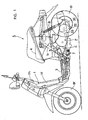
- Fig. 1 is a side view of a motorcycle loaded with a power unit having a pinion-shaft support structure for starter according to the present invention
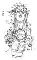
- Fig. 2 an enlarged side view of the power unit
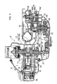
- Fig. 3 a cross-sectional view along a line 3-3 in Fig. 2
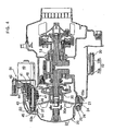
- Fig. 4 a cross-sectional view along a line 4-4 in Fig. 2
- Fig. 5, a cross-sectional view along a line 5-5 in Fig. 2.
- a vehicle body frame 1 of a motorcycle S has a front frame 1f which extends downward from a head pipe 1 steerably supporting a front fork 2 and which supports a step floor 3, and a rear frame 1r which extends diagonally upward from a rear end of the front frame 1f and which supports a luggage box 4 and a passenger seat 5.
- a front wheel 6f is supported at a lower end of the front fork 2.
- a power unit P which drives a rear wheel 6r while supporting the rear wheel is suspended upward/downward swingably from the rear frame 1r via a suspension link 7.
- a rear cushion 8 which cushions the upward/downward swing of the power unit P is attached between the rear frame 1r and the power unit P.
- the motorcycle S is constructed to have a form of scooter.
- an engine E of the power unit P has a crankcase 10, a cylinder block 11 coupled in a forward-canted position to a front end of the crankcase 10, and a cylinder head 12 joined to a front end of the cylinder block 11, as an engine main body.
- a crankshaft 13 which is provided in a leftward/rightward horizontal direction is supported with the crankcase 10
- a piston 15 connected to the crankshaft 13 via a connecting rod 14 is fitted into a cylinder bore 11a of the cylinder block 11.
- An ignition plug 16 and valve train 17 are provided in the cylinder head 12.
- a head cover 18 covering the valve train 17 is joined to a front end surface of the cylinder head 12.
- crankcase 10 is divided into a left and right case half bodies 10a and 10b by a vertical plane including an axial line of the cylinder bore 11a and they are joined to each other by plural bolts 20 in peripheral portions.
- the left and right ends of the crankshaft 13 are supported via bearings with the both case half bodies 10a and 10b.
- the left case half body 10a has an extended portion 10 a' extending rearward.
- a transmission case 23 is constructed with the left case half body 10a and the transmission cover 22 joined to an outer side wall of the left case half body via a gasket 21 having elasticity.
- the transmission cover 22 is fastened to the crankcase 10 by plural bolts 25, 25... inserted into plural through holes 24, 24... in the peripheral portion of the cover.
- a grommeted elastic member 26 in a contracted status is inserted between the respective bolts 25 and peripheral portions of the through holes 24 of the transmission cover 22 to avoid direct contact therebetween.
- a flange 25a See Fig.
- a belt-type continuously variable transmission T and a speed reducing unit R are accommodated in the above-described transmission case 23. Further, the rear wheel 6r is supported at a rear end of the transmission case 23 and a lower end of a rear cushion 7 is attached to the rear end of the transmission case.
- the continuously variable transmission T has a drive pulley 30 of variable pitch diameter type provided at an end of the crankshaft 13, a driven pulley 31 of variable pitch diameter type provided on an input shaft 34 of the speed reducing unit R via a centrifugal clutch 33, and an endless belt 32 put between the above-described both pulleys 30 and 31.
- the continuously variable transmission automatically connects the centrifugal clutch 33 and performs transmission between the drive pulley 30 and the driven pulley 31 in correspondence with the increase in the number of revolutions of the crankshaft 13.
- a ring gear 37 with which the pinion 46 of the starter to be described later is engaged is formed in the peripheral portion of a fixed pulley half body 30a fixed on the tip side of the crankshaft 13 of the drive pulley 30.
- the speed reducing unit R is constructed with 2 arrays of speed reducing gear arrays 36a and 36b, provided between the input shaft 34 and an output shaft 35, to decelerate the rotation of the input shaft 34 by 2 steps and transmit the rotation to the output shaft 35.
- the rear wheel 6r is attached to an outer end of the output shaft 35.
- a starter motor 40 is attached to the left case half body 10a with a bolt 42 such that its output shaft 41 parallel to the crankshaft 13 is inserted in the transmission case 23.
- a starter St is constructed with the starter motor 40 and a starting transmission mechanism 43 which transmits the rotation of the output shaft 35 to the ring gear 37.
- the starting transmission mechanism 43 which is well known, comprises a pinion shaft 45 connected to the output shaft 41 of the starter motor 40 via a speed reducing gear array 44, a pinion 46 engageable and removable with/from the ring gear 37 and supported on the above-described pinion shaft 45 movably in an axial direction, and an eject mechanism 47 which shifts the pinion 46 to engage it with the ring gear 37 upon rotation of the pinion shaft 45.
- pinion shaft 45 is supported with a bearing 48 integrally formed with the side wall of the left case half body 10a facing the inside of the transmission case 23, via a bush 53. Further, the other end is supported with a bearing boss 50a of a pinion holder 50 provided in the transmission case 23, via a bush 54.
- the above-described pinion holder 50 have plural attachment ribs 50b, 50b integrally-formed with the pinion holder, provided at equal intervals around the bearing boss 50a, illustrated as a pair of attachment ribs 50b, 50b provided with a pitch of 180°.
- support members 49, 49 which extend from a joint surface with the transmission cover 22 and which receive the above-described attachment ribs 50b, 50b, are integrally formed with the left case half body 10a.
- the attachment ribs 50b, 50b are integrally fixed to these support members 49, 49 with bolts 51 and 52.
- the one bolt 51 exclusively relates to fixing of the corresponding attachment rib 50b, while the bolt 52 also relates to joining of the transmission cover 22 to the left case half body 10a as a oddly-shaped bolt.
- the bolt 51 is provided in the vicinity of the output shaft 41 of the starter motor 40.
- the shaft of the oddly-shaped bolt 52 is longer than the shaft of the other bolt 51 such that the former shaft is passed through a through hole 24 formed in a peripheral portion of the transmission cover 22.
- a flange 52a which fastens the corresponding attachment rib 50b toward the left case half body 10a is integrally formed with a middle portion of the shaft of the oddly-shaped bolt, and further, a flanged hexagonal head 52b opposed to an outer side surface of the transmission cover 22 so as to press the outer side surface is integrally formed with an outer end of the shaft.
- the grommeted elastic member 26 in a contracted status is provided between the oddly-shaped bolt 52 and the peripheral portion of the through hole 24 of the transmission cover 22 so as to avoid direct contact therebetween.
- the flange 52a fastens the rib 50b to the support member 49, thus firmly fixing the pinion holder 50 to the left case half body 10a in cooperation with the bolt 51, and at the same time, provides the gasket 21 and the elastic member 26 with appropriate fastening widths, which maintains floating support of the transmission cover 22.
- the bearing boss 50a can be prevented from tilting by uniformly distributing a fixing force for the pinion holder 50 to the left case half body 10a around the bearing boss 50a, thereby a proper position of the pinion shaft 45 and accordingly, a proper position of the pinion 46 can be maintained.
- the oddly-shaped bolt 52 out of the above-described bolts is also used for joining the transmission cover 22 to the left case half body 10a
- the initial number of the plural bolts 25, 25... for joining the transmission cover 22 to the left case half body 10a can be reduced by the use of the oddly-shaped bolt, and accordingly, the number of assembly steps can be reduced, thus the costs can be reduced.
- the elastic member 26 in a contracted status is provided between the oddly-shaped bolt 52 and the peripheral portion of the through hole 24 of the transmission cover 22, the floating status of the transmission cover 22 can be maintained, and the occurrence of vibration noise from the transmission cover 22 can be prevented.
- the normal bolt 51 exclusively for fixing is also used for fixing the pinion holder 50 to the left case half body 10a.
- the one attachment rib 50b of the pinion holder 50 is first fixed to the support member 49 of the left case half body 10a with the normal bolt 51, and at the same time, positioning between the other attachment rib 50b and the corresponding support member 49 is made.
- the oddly-shaped bolt 52 is operated with the bolts 25, 25... to join the transmission cover 22 to the left case half body 10a, as the other attachment rib 50b can be firmly fixed to the corresponding support member 49 with the oddly-shaped bolt 52, the assembly can be excellently made.
- a transmission cover constructing a transmission case accommodating a transmission in cooperation with one side wall of a crankcase of an engine is joined to the one side wall via a gasket having elasticity, and one end of a pinion shaft coupled to an output shaft of a starter motor supported with the crankcase and supporting a pinion engaged and removable with/from a ring gear of the engine, movably in an axial direction, is rotatably supported on one side wall of the crankcase facing the inside of said transmission case and the other end is rotatably supported with a pinion holder provided in said transmission case, said pinion holder is fixed to the crankcase with fastening members.
- the both ends of the pinion shaft are firmly supported with the crankcase and the pinion holder integrally fixed with the crankcase in the transmission case thereby the durability of the pinion shaft is improved, and the vibration of the shaft during rotation is suppressed. Accordingly, the engagement status between the pinion and the ring gear can be appropriately maintained and the occurrence of noise from the engaged portion can be prevented as much as possible.
- another fastening member that fastens said transmission cover to the crankcase side via an elastic member is integrally formed with said fastening member. Accordingly, as the same fastening member can be used for fixing the pinion holder to the crankcase and joining the transmission cover to the crankcase, the number of parts and the number of assembly steps can be reduced.
- a portion of said pinion holder fastened to the crankcase is provided in plural positions at equal intervals around a bearing boss of the pinion holder supporting said pinion shaft. Accordingly, the bearing boss can be prevented from tilting by distributing a fastening force for the pinion holder to the crankcase uniformly around the bearing boss, and a proper position of the pinion shaft and accordingly, a proper position of the pinion can be maintained.
- the structure further comprises a specialized fastening member that exclusively fixes the pinion holder to the crankcase as well as the fastening member integrally formed with said other fastening member.
- a specialized fastening member that exclusively fixes the pinion holder to the crankcase as well as the fastening member integrally formed with said other fastening member.
- a transmission cover constructing a transmission case accommodating a transmission in cooperation with one side wall of a crankcase of an engine, is joined to the one side wall via a gasket having elasticity, and wherein one end of a pinion shaft coupled to an output shaft of a starter motor supported with the crankcase and supporting a pinion engaged and removable with/from a ring gear of the engine, movably in an axial direction, is rotatably supported on one side wall of the crankcase facing the inside of said transmission case and the other end is rotatably supported with a pinion holder provided in said transmission case, said pinion holder is fixed to the crankcase with plural bolts in plural positions at equal intervals around said pinion shaft, and another fastening member that fastens said transmission cover to the crankcase side via an elastic member is integrally formed with a part of those said fastening bolts.
- Means of Solution In a case where one end of a pinion shaft 45 supporting a pinion 46 movably in an axial direction is supported with a bearing boss 48 which faces the inside of the transmission case 23 and which is formed in a crankcase 10, and the other end is supported with a boss 50a of a pinion holder 50 provided in the transmission case 23, the pinion holder 50 is integrally fixed to the crankcase 10 with plural bolts 51 and 52 surrounding the boss 50a at equal intervals.
Abstract
Description
- The present invention relates to a pinion-shaft support structure for starter in power unit, in which, a transmission cover constructing a transmission case accommodating a transmission in cooperation with one side wall of a crankcase of an engine, is joined to the one side wall via a gasket having elasticity, and one end of a pinion shaft coupled to an output shaft of a starter motor supported with the crankcase and supporting a pinion engaged and removable with/from a ring gear of the engine, movably in an axial direction, is rotatably supported on one side wall of the crankcase facing the inside of said transmission case and the other end is rotatably supported with a pinion holder provided in said transmission case.
- Conventionally, in a pinion-shaft support structure for a starter in such power unit, as disclosed in, e.g., Japanese Utility-Model Registration No. 2,582,275, an elastic support member in a contracted status is provided between a pinion holder and a transmission cover such that the pinion holder is held on one side wall of the crankcase by a repulsive force of the elastic support member.
- To prevent the occurrence of noise due to engine vibration, the transmission cover is joined to the crankcase via a gasket having elasticity. In a case where the pinion holder is joined to the crankcase via the elastic support member by using this transmission cover as in the above-described conventional art, the pinion holder cannot be firmly supported on the crankcase, and the durability of the pinion shaft cannot be improved without difficulty.
- The present invention has been made in view of the above situation, and has its object to provide a pinion-shaft support structure for starter in power unit which enables firm support of the pinion holder on the crankcase thereby ensures the durability of the pinion shaft.
- To attain the foregoing object, the present invention provides as a first feature that in a power unit, in which a transmission cover constructing a transmission case accommodating a transmission in cooperation with one side wall of a crankcase of an engine, is joined to the one side wall via a gasket having elasticity, and wherein one end of a pinion shaft coupled to an output shaft of a starter motor supported with the crankcase and supporting a pinion engaged and removable with/from a ring gear of the engine, movably in an axial direction, is rotatably supported on one side wall of the crankcase facing the inside of said transmission case and the other end is rotatably supported with a pinion holder provided in said transmission case, said pinion holder is fixed to the crankcase by fastening members.
- Note that the above-described fastening members correspond to a
bolt 51 and an oddly-shaped bolt 52 in the embodiment of the present invention to be described later. - According to the first feature, the both ends of the pinion shaft are firmly supported with the crankcase and the pinion holder integrally fixed to the crankcase in the transmission case, thereby the durability of the pinion shaft can be improved, and the vibration of the shaft during its rotation can be suppressed. Accordingly, a proper engagement status between the pinion and the ring gear can be maintained, and the occurrence of noise from the engagement portion can be prevented as much as possible.
- Further, the present invention provides a second feature, in addition to the first feature, that another fastening member that fastens said transmission cover to the crankcase side via an elastic member is integrally formed with said fastening member.
- Note that the above-described fastening member corresponds to the oddly-
shaped bolt 52 in the embodiment of the present invention to be described later, and the above-described other fastening member corresponds to a flangedhexagonal head 52b of the oddly-shaped bolt 52. - According to the second feature, as the same fastening member can be used for fixing the pinion holder to the crankcase and joining the transmission cover to the crankcase, the number of parts and the number of assembly steps can be reduced.
- Further, the present invention provides a third feature, in addition to the first feature, that a portion of said pinion holder fastened to the crankcase is provided in plural positions at equal intervals around a bearing boss of the pinion holder supporting said pinion shaft.
- According to the third feature, the bearing boss can be prevented from tilting by distributing a fastening force for the pinion holder to the crankcase uniformly around the bearing boss, and a proper position of the pinion shaft and accordingly, a proper position of the pinion can be maintained.
- Further, the present invention provides a fourth feature, in addition to the second feature, that the structure further comprises a specialized fastening member that exclusively fixes the pinion holder to the crankcase as well as the fastening member integrally formed with said other fastening member.
- The specialized fastening member corresponds to the
bolt 51 in the embodiment of the present invention to be described later. - According to the fourth feature, upon assembly, first, a portion of the pinion holder is fixed to the crankcase by the specialized fastening member, and when finally the transmission cover is joined to the crankcase, the other portion of the pinion holder can be fixed to the crankcase by operating the fastening member having said other fastening member, thereby the assembly can be excellently made.
- Further, the present invention provides as a fifth feature that in a power unit, in which a transmission cover constructing a transmission case accommodating a transmission in cooperation with one side wall of a crankcase of an engine, is joined to the one side wall via a gasket having elasticity, and wherein one end of a pinion shaft coupled to an output shaft of a starter motor supported with the crankcase and supporting a pinion engaged and removable with/from a ring gear of the engine, movably in an axial direction, is rotatably supported on one side wall of the crankcase facing the inside of said transmission case and the other end is rotatably supported with a pinion holder provided in said transmission case, said pinion holder is fixed to the crankcase with plural bolts in plural positions at equal intervals around said pinion shaft, and another fastening member that fastens said transmission cover to the crankcase side via an elastic member is integrally formed with a part of those said fastening bolts.
- According to the fifth feature, the operations by the above-described first to fourth features can be attained at once.
- A working example of the present invention will be described below in accordance with an embodiment of the present invention shown in the attached drawings.
- It is illustrated in:
- Fig. 1; A side view of the motorcycle loaded with the power unit having the pinion-shaft support structure for starter according to the present invention.
- Fig. 2: An enlarged side view of the power unit.
- Fig. 3: A cross-sectional view along a line 3-3 in Fig. 2.
- Fig. 4: A cross-sectional view along a line 4-4 in Fig. 2.
- Fig. 5: A cross-sectional view along a line 5-5 in Fig. 2.
-
- Fig. 1 is a side view of a motorcycle loaded with a power unit having a pinion-shaft support structure for starter according to the present invention; Fig. 2, an enlarged side view of the power unit; Fig. 3, a cross-sectional view along a line 3-3 in Fig. 2; Fig. 4, a cross-sectional view along a line 4-4 in Fig. 2; and Fig. 5, a cross-sectional view along a line 5-5 in Fig. 2.
- Note that in the following description, front/rear and left/right are used with the motorcycle as a reference.
- First, in Fig. 1, a
vehicle body frame 1 of a motorcycle S has a front frame 1f which extends downward from ahead pipe 1 steerably supporting a front fork 2 and which supports astep floor 3, and arear frame 1r which extends diagonally upward from a rear end of the front frame 1f and which supports aluggage box 4 and a passenger seat 5. Afront wheel 6f is supported at a lower end of the front fork 2. A power unit P which drives arear wheel 6r while supporting the rear wheel is suspended upward/downward swingably from therear frame 1r via asuspension link 7. Arear cushion 8 which cushions the upward/downward swing of the power unit P is attached between therear frame 1r and the power unit P. Thus, the motorcycle S is constructed to have a form of scooter. - As shown in Figs. 2 to 4, an engine E of the power unit P has a
crankcase 10, acylinder block 11 coupled in a forward-canted position to a front end of thecrankcase 10, and acylinder head 12 joined to a front end of thecylinder block 11, as an engine main body. Acrankshaft 13 which is provided in a leftward/rightward horizontal direction is supported with the crankcase 10A piston 15 connected to thecrankshaft 13 via a connectingrod 14 is fitted into acylinder bore 11a of thecylinder block 11. Anignition plug 16 andvalve train 17 are provided in thecylinder head 12. Ahead cover 18 covering thevalve train 17 is joined to a front end surface of thecylinder head 12. - The
crankcase 10 is divided into a left and rightcase half bodies plural bolts 20 in peripheral portions. The left and right ends of thecrankshaft 13 are supported via bearings with the bothcase half bodies - The left case
half body 10a has an extendedportion 10 a' extending rearward. Atransmission case 23 is constructed with the leftcase half body 10a and thetransmission cover 22 joined to an outer side wall of the left case half body via agasket 21 having elasticity. At this time, thetransmission cover 22 is fastened to thecrankcase 10 byplural bolts holes elastic member 26 in a contracted status is inserted between therespective bolts 25 and peripheral portions of the throughholes 24 of thetransmission cover 22 to avoid direct contact therebetween. Further, aflange 25a (See Fig. 4) in contact with an outer surface of thecrankcase 10 is formed on the shafts of therespective bolts 25 so as to firmly engage therespective bolts 25 with the screw holes of thecrankcase 10 but not to add excessive fastening widths to thegasket 21 and theelastic member 26. Thus, thetransmission cover 22, floating-supported with theelastic member 26 and thegasket 21, blocks transmission of the vibration of the engine E from thecrankcase 10 to thetransmission cover 22, thereby prevents the occurrence of vibration noise from thetransmission cover 22. - A belt-type continuously variable transmission T and a speed reducing unit R are accommodated in the above-described
transmission case 23. Further, therear wheel 6r is supported at a rear end of thetransmission case 23 and a lower end of arear cushion 7 is attached to the rear end of the transmission case. - The continuously variable transmission T has a
drive pulley 30 of variable pitch diameter type provided at an end of thecrankshaft 13, a drivenpulley 31 of variable pitch diameter type provided on aninput shaft 34 of the speed reducing unit R via acentrifugal clutch 33, and anendless belt 32 put between the above-described bothpulleys centrifugal clutch 33 and performs transmission between thedrive pulley 30 and the drivenpulley 31 in correspondence with the increase in the number of revolutions of thecrankshaft 13. Aring gear 37 with which thepinion 46 of the starter to be described later is engaged is formed in the peripheral portion of a fixed pulleyhalf body 30a fixed on the tip side of thecrankshaft 13 of thedrive pulley 30. - Further, the speed reducing unit R is constructed with 2 arrays of speed reducing
gear arrays 36a and 36b, provided between theinput shaft 34 and anoutput shaft 35, to decelerate the rotation of theinput shaft 34 by 2 steps and transmit the rotation to theoutput shaft 35. Therear wheel 6r is attached to an outer end of theoutput shaft 35. - As shown in Figs. 4 and 5, a
starter motor 40 is attached to the left casehalf body 10a with abolt 42 such that itsoutput shaft 41 parallel to thecrankshaft 13 is inserted in thetransmission case 23. A starter St is constructed with thestarter motor 40 and astarting transmission mechanism 43 which transmits the rotation of theoutput shaft 35 to thering gear 37. Thestarting transmission mechanism 43, which is well known, comprises apinion shaft 45 connected to theoutput shaft 41 of thestarter motor 40 via a speed reducinggear array 44, apinion 46 engageable and removable with/from thering gear 37 and supported on the above-describedpinion shaft 45 movably in an axial direction, and an eject mechanism 47 which shifts thepinion 46 to engage it with thering gear 37 upon rotation of thepinion shaft 45. - One end of the above-described
pinion shaft 45 is supported with abearing 48 integrally formed with the side wall of the left casehalf body 10a facing the inside of thetransmission case 23, via abush 53. Further, the other end is supported with abearing boss 50a of apinion holder 50 provided in thetransmission case 23, via abush 54. - The above-described
pinion holder 50 haveplural attachment ribs bearing boss 50a, illustrated as a pair ofattachment ribs members transmission cover 22 and which receive the above-describedattachment ribs half body 10a. Theattachment ribs support members bolts bolt 51 exclusively relates to fixing of thecorresponding attachment rib 50b, while thebolt 52 also relates to joining of thetransmission cover 22 to the left casehalf body 10a as a oddly-shaped bolt. Especially, thebolt 51 is provided in the vicinity of theoutput shaft 41 of thestarter motor 40. - That is, the shaft of the oddly-
shaped bolt 52 is longer than the shaft of theother bolt 51 such that the former shaft is passed through a throughhole 24 formed in a peripheral portion of thetransmission cover 22. Aflange 52a which fastens thecorresponding attachment rib 50b toward the left casehalf body 10a is integrally formed with a middle portion of the shaft of the oddly-shaped bolt, and further, a flangedhexagonal head 52b opposed to an outer side surface of thetransmission cover 22 so as to press the outer side surface is integrally formed with an outer end of the shaft. The grommetedelastic member 26 in a contracted status is provided between the oddly-shaped bolt 52 and the peripheral portion of thethrough hole 24 of thetransmission cover 22 so as to avoid direct contact therebetween. When theelastic member 26 is attached to the throughhole 24 and the oddly-shaped bolt 52 inserted through the hole is engaged with a screw hole of thecorresponding support member 49, theflange 52a fastens therib 50b to thesupport member 49, thus firmly fixing thepinion holder 50 to the leftcase half body 10a in cooperation with thebolt 51, and at the same time, provides thegasket 21 and theelastic member 26 with appropriate fastening widths, which maintains floating support of thetransmission cover 22. - Next, an operation of the embodiment will be described.
- When the
starter motor 40 is activated so as to start the engine E, as thepinion 46 is engaged with thering gear 37 in accordance with the rotation of thepinion shaft 45 and drives the ring gear, thecrankshaft 13 is cranked from thering gear 37, thus starting is made. During this time, as therotating pinion shaft 45 is firmly supported with the bearingboss 48 of the left casehalf body 10a and the bearingboss 50a of thepinion holder 50 integrally fixed to the left casehalf body 10a, the occurrence of vibration can be prevented. Accordingly, the durability of thepinion shaft 45 can be improved, the support of thepinion 46 is stabilized thereby the engagement status between thepinion 46 and thering gear 37 is appropriately maintained, and the occurrence of noise from the engaged portion can be prevented as much as possible. - Especially, as the
pinion holder 50 is fixed to the left casehalf body 10a with theplural bolts boss 50a, the bearingboss 50a can be prevented from tilting by uniformly distributing a fixing force for thepinion holder 50 to the left casehalf body 10a around the bearingboss 50a, thereby a proper position of thepinion shaft 45 and accordingly, a proper position of thepinion 46 can be maintained. - Further, as the
normal bolt 51, which is first fastened, out of the above-describedplural bolts output shaft 41 of thestarter motor 40, an actuation reaction force of theoutput shaft 41 of thestarter motor 40 can be effectively supported. - Further, as the oddly-shaped
bolt 52 out of the above-described bolts is also used for joining thetransmission cover 22 to the left casehalf body 10a, the initial number of theplural bolts transmission cover 22 to the left casehalf body 10a can be reduced by the use of the oddly-shaped bolt, and accordingly, the number of assembly steps can be reduced, thus the costs can be reduced. Further, as theelastic member 26 in a contracted status is provided between the oddly-shapedbolt 52 and the peripheral portion of the throughhole 24 of thetransmission cover 22, the floating status of thetransmission cover 22 can be maintained, and the occurrence of vibration noise from thetransmission cover 22 can be prevented. - Further, the
normal bolt 51 exclusively for fixing is also used for fixing thepinion holder 50 to the left casehalf body 10a. Upon assembly, the oneattachment rib 50b of thepinion holder 50 is first fixed to thesupport member 49 of the left casehalf body 10a with thenormal bolt 51, and at the same time, positioning between theother attachment rib 50b and thecorresponding support member 49 is made. Accordingly, when finally the oddly-shapedbolt 52 is operated with thebolts transmission cover 22 to the left casehalf body 10a, as theother attachment rib 50b can be firmly fixed to thecorresponding support member 49 with the oddly-shapedbolt 52, the assembly can be excellently made. - The present invention is not limited to the above-described embodiment, but various design changes can be made within a scope without departing from the subject matter.
- As described above, according to the first feature of the present invention, in a power unit, a transmission cover constructing a transmission case accommodating a transmission in cooperation with one side wall of a crankcase of an engine, is joined to the one side wall via a gasket having elasticity, and one end of a pinion shaft coupled to an output shaft of a starter motor supported with the crankcase and supporting a pinion engaged and removable with/from a ring gear of the engine, movably in an axial direction, is rotatably supported on one side wall of the crankcase facing the inside of said transmission case and the other end is rotatably supported with a pinion holder provided in said transmission case, said pinion holder is fixed to the crankcase with fastening members. The both ends of the pinion shaft are firmly supported with the crankcase and the pinion holder integrally fixed with the crankcase in the transmission case thereby the durability of the pinion shaft is improved, and the vibration of the shaft during rotation is suppressed. Accordingly, the engagement status between the pinion and the ring gear can be appropriately maintained and the occurrence of noise from the engaged portion can be prevented as much as possible.
- Further, according to the second feature of the present invention, in addition to the first feature, another fastening member that fastens said transmission cover to the crankcase side via an elastic member is integrally formed with said fastening member. Accordingly, as the same fastening member can be used for fixing the pinion holder to the crankcase and joining the transmission cover to the crankcase, the number of parts and the number of assembly steps can be reduced.
- Further, according to the third feature of the present invention, in addition to the first feature, a portion of said pinion holder fastened to the crankcase is provided in plural positions at equal intervals around a bearing boss of the pinion holder supporting said pinion shaft. Accordingly, the bearing boss can be prevented from tilting by distributing a fastening force for the pinion holder to the crankcase uniformly around the bearing boss, and a proper position of the pinion shaft and accordingly, a proper position of the pinion can be maintained.
- Further, according to the fourth feature, in addition to the second feature, the structure further comprises a specialized fastening member that exclusively fixes the pinion holder to the crankcase as well as the fastening member integrally formed with said other fastening member. Upon assembly, first, one portion of the pinion holder is fixed to the crankcase with the specialized fastening member, and when finally the transmission cover is joined to the crankcase, the other portion of the pinion holder can be fixed to the crankcase by operating the fastening member having said other fastening member, thereby the assembly can be excellently made.
- Further, according to the fifth feature of the present invention, in a power unit, a transmission cover constructing a transmission case accommodating a transmission in cooperation with one side wall of a crankcase of an engine, is joined to the one side wall via a gasket having elasticity, and wherein one end of a pinion shaft coupled to an output shaft of a starter motor supported with the crankcase and supporting a pinion engaged and removable with/from a ring gear of the engine, movably in an axial direction, is rotatably supported on one side wall of the crankcase facing the inside of said transmission case and the other end is rotatably supported with a pinion holder provided in said transmission case, said pinion holder is fixed to the crankcase with plural bolts in plural positions at equal intervals around said pinion shaft, and another fastening member that fastens said transmission cover to the crankcase side via an elastic member is integrally formed with a part of those said fastening bolts. Accordingly, the operations by the above-described first to fourth features can be attained at once.
Object: To provide a pinion-shaft support structure for starter in a power unit which can firmly fix a pinion holder to a crankcase thereby ensure stable supporting of the pinion shaft. - Means of Solution: In a case where one end of a
pinion shaft 45 supporting apinion 46 movably in an axial direction is supported with a bearingboss 48 which faces the inside of thetransmission case 23 and which is formed in acrankcase 10, and the other end is supported with aboss 50a of apinion holder 50 provided in thetransmission case 23, thepinion holder 50 is integrally fixed to thecrankcase 10 withplural bolts boss 50a at equal intervals.
Claims (5)
- A pinion-shaft support structure for starter in power unit, in which in the power unit, a transmission cover (22) constructing a transmission case (23) accommodating a transmission (T) in cooperation with one side wall of a crankcase (10) of an engine (E), is joined to the one side wall via a gasket (21) having elasticity, and one end of a pinion shaft (45) coupled to an output shaft (41) of a starter motor (40) supported with the crankcase (10) and supporting a pinion (46) engaged and removable with/from a ring gear (37) of the engine (E), movably in an axial direction, is rotatably supported on one side wall of the crankcase (10) facing the inside of said transmission case (23) and the other end is rotatably supported with a pinion holder (50) provided in said transmission case (23),
wherein said pinion holder (50) is fixed to the crankcase (10) with fastening members (51, 52). - The pinion-shaft support structure for starter in power unit according to claim 1,
wherein another fastening member (52b) that fastens said transmission cover (22) to the crankcase (10) side via an elastic member (26) is integrally formed with said fastening member (52). - The pinion-shaft support structure for starter in power unit according to claim 1,
wherein a portion (49) of said pinion holder (50) fastened to the crankcase (10) is provided in plural positions at equal intervals around a bearing boss (50a) of the pinion holder (50) supporting said pinion shaft (45). - The pinion-shaft support structure for starter in power unit according to claim 2,
wherein the structure further comprises a specialized fastening member (51) that exclusively fixes the pinion holder (50) to the crankcase (10) as well as the fastening member (52) integrally formed with said other fastening member (52b). - A pinion-shaft support structure for starter in power unit, in which in the power unit, a transmission cover (22) constructing a transmission case (23) accommodating a transmission (T) in cooperation with one side wall of a crankcase (10) of an engine (E), is joined to the one side wall via a gasket (21) having elasticity, and one end of a pinion shaft (45) coupled to an output shaft (41) of a starter motor (40) supported with the crankcase (10) and supporting a pinion (46) engaged and removable with/from a ring gear (37) of the engine (E), movably in an axial direction, is rotatably supported on one side wall of the crankcase (10) facing the inside of said transmission case (23) and the other end is rotatably supported with a pinion holder (50) provided in said transmission case (23),
wherein said pinion holder (50) is fixed to the crankcase (10) with plural bolts (51, 52) in plural positions at equal intervals around said pinion shaft (45), and wherein another fastening member (52b) that fastens said transmission cover (22) to the crankcase (10) side via an elastic member (26) is integrally formed with a part of those said fastening bolts (52).
Applications Claiming Priority (2)
| Application Number | Priority Date | Filing Date | Title |
|---|---|---|---|
| JP2002178025A JP4007863B2 (en) | 2002-06-19 | 2002-06-19 | Support structure of starter pinion support shaft in power unit |
| JP2002178025 | 2002-06-19 |
Publications (2)
| Publication Number | Publication Date |
|---|---|
| EP1375909A2 true EP1375909A2 (en) | 2004-01-02 |
| EP1375909A3 EP1375909A3 (en) | 2006-09-06 |
Family
ID=29717476
Family Applications (1)
| Application Number | Title | Priority Date | Filing Date |
|---|---|---|---|
| EP03010409A Withdrawn EP1375909A3 (en) | 2002-06-19 | 2003-05-08 | Pinion-shaft support structure for starter in power unit |
Country Status (4)
| Country | Link |
|---|---|
| EP (1) | EP1375909A3 (en) |
| JP (1) | JP4007863B2 (en) |
| CN (1) | CN1249338C (en) |
| TW (1) | TW589438B (en) |
Cited By (3)
| Publication number | Priority date | Publication date | Assignee | Title |
|---|---|---|---|---|
| EP2112346A1 (en) * | 2007-02-09 | 2009-10-28 | Yamaha Hatsudoki Kabushiki Kaisha | Straddle-type vehicle |
| CN110081154A (en) * | 2019-03-11 | 2019-08-02 | 全椒瑞禾动力机械有限公司 | A kind of gear chamber cover blank and gear chamber cover processing method |
| US20200224628A1 (en) * | 2017-10-03 | 2020-07-16 | Polaris Industries Inc. | Crankcase Mounts And Reinforced Rubber In Mount On Force Vector |
Families Citing this family (4)
| Publication number | Priority date | Publication date | Assignee | Title |
|---|---|---|---|---|
| JP2008095561A (en) * | 2006-10-06 | 2008-04-24 | Suzuki Motor Corp | Engine starter |
| JP5056406B2 (en) * | 2007-02-05 | 2012-10-24 | 日産自動車株式会社 | Starter mounting structure for starting the engine |
| JP2008202628A (en) * | 2007-02-16 | 2008-09-04 | Yamaha Motor Co Ltd | Transmission and engine unit equipped with the same |
| KR100998334B1 (en) | 2009-01-08 | 2010-12-06 | 다이모스(주) | Axle Carrier |
Citations (1)
| Publication number | Priority date | Publication date | Assignee | Title |
|---|---|---|---|---|
| JP2582275B2 (en) | 1987-10-15 | 1997-02-19 | 株式会社コーセー | Silicone gel composition and cosmetic containing the same |
Family Cites Families (5)
| Publication number | Priority date | Publication date | Assignee | Title |
|---|---|---|---|---|
| US3020771A (en) * | 1959-07-30 | 1962-02-13 | Gen Motors Corp | Engine starter |
| AT334140B (en) * | 1971-04-21 | 1976-12-27 | Steyr Daimler Puch Ag | DEVICE FOR FASTENING THE FRONT OF A STARTER TO A FLANGE OF AN COMBUSTION ENGINE |
| FR2378954A1 (en) * | 1976-12-22 | 1978-08-25 | Paris & Du Rhone | PERFECTED INTERMEDIATE FALSE-BEARING STARTER |
| ES2117525B1 (en) * | 1994-12-27 | 1999-04-01 | Honda Motor Co Ltd | STARTER SUPPORT MECHANISM TO SUPPORT THE MOTOR STARTER FOR MOTORCYCLE. |
| JP3391426B2 (en) * | 1995-08-09 | 2003-03-31 | 本田技研工業株式会社 | Mounting structure of the reduction gear of the starter motor |
-
2002
- 2002-06-19 JP JP2002178025A patent/JP4007863B2/en not_active Expired - Fee Related
-
2003
- 2003-03-31 TW TW92107259A patent/TW589438B/en not_active IP Right Cessation
- 2003-05-08 EP EP03010409A patent/EP1375909A3/en not_active Withdrawn
- 2003-06-05 CN CN 03141174 patent/CN1249338C/en not_active Expired - Fee Related
Patent Citations (1)
| Publication number | Priority date | Publication date | Assignee | Title |
|---|---|---|---|---|
| JP2582275B2 (en) | 1987-10-15 | 1997-02-19 | 株式会社コーセー | Silicone gel composition and cosmetic containing the same |
Cited By (4)
| Publication number | Priority date | Publication date | Assignee | Title |
|---|---|---|---|---|
| EP2112346A1 (en) * | 2007-02-09 | 2009-10-28 | Yamaha Hatsudoki Kabushiki Kaisha | Straddle-type vehicle |
| US20200224628A1 (en) * | 2017-10-03 | 2020-07-16 | Polaris Industries Inc. | Crankcase Mounts And Reinforced Rubber In Mount On Force Vector |
| US11668272B2 (en) * | 2017-10-03 | 2023-06-06 | Polaris Industries Inc. | Crankcase mounts and reinforced rubber in mount on force vector |
| CN110081154A (en) * | 2019-03-11 | 2019-08-02 | 全椒瑞禾动力机械有限公司 | A kind of gear chamber cover blank and gear chamber cover processing method |
Also Published As
| Publication number | Publication date |
|---|---|
| JP4007863B2 (en) | 2007-11-14 |
| TW589438B (en) | 2004-06-01 |
| TW200400321A (en) | 2004-01-01 |
| JP2004019604A (en) | 2004-01-22 |
| CN1249338C (en) | 2006-04-05 |
| EP1375909A3 (en) | 2006-09-06 |
| CN1482353A (en) | 2004-03-17 |
Similar Documents
| Publication | Publication Date | Title |
|---|---|---|
| CN1057499C (en) | Auxiliary power device for bicycle and bicycle equipped with the auxiliary power device | |
| US7731613B2 (en) | V-belt type continuously variable transmission, saddle-ride type vehicle, and method of manufacturing the V-belt type continuously variable transmission | |
| JP5506601B2 (en) | Continuously variable transmission structure | |
| JP4083837B2 (en) | Vehicle engine support device | |
| JP2002079982A (en) | Motorcycle | |
| JP7261645B2 (en) | hybrid vehicle | |
| JP2007321790A (en) | Engine unit and suddling type vehicle | |
| JP3823630B2 (en) | Motorcycle transmission | |
| EP1375909A2 (en) | Pinion-shaft support structure for starter in power unit | |
| US5992355A (en) | Power unit of a saddle-seat vehicle | |
| US7540348B2 (en) | Power unit for motorcycle and motorcycle | |
| US10619720B2 (en) | Transmission | |
| CN101008448A (en) | Sealing structure for belt stepless transmission and belt stepless transmission | |
| JP5654389B2 (en) | Continuous transmission structure | |
| US7628131B2 (en) | Engine for vehicle | |
| EP1666721B1 (en) | Internal combustion engine | |
| JP2003193854A (en) | Internal combustion engine | |
| JP2001080567A (en) | Transmission of motorcycle | |
| EP2546550B1 (en) | Transmission apparatus and saddle type vehicle including the same | |
| JP3156419U (en) | Engine unit and saddle riding type vehicle | |
| CN109789762B (en) | Drive system for hybrid vehicle | |
| JP6071579B2 (en) | Bearing structure of rotating shaft | |
| JP5386274B2 (en) | Motorcycle | |
| JP4879579B2 (en) | Power unit for vehicle | |
| WO2018042317A1 (en) | Location for arrangement of the starting system |
Legal Events
| Date | Code | Title | Description |
|---|---|---|---|
| PUAI | Public reference made under article 153(3) epc to a published international application that has entered the european phase |
Free format text: ORIGINAL CODE: 0009012 |
|
| AK | Designated contracting states |
Kind code of ref document: A2 Designated state(s): AT BE BG CH CY CZ DE DK EE ES FI FR GB GR HU IE IT LI LU MC NL PT RO SE SI SK TR |
|
| AX | Request for extension of the european patent |
Extension state: AL LT LV MK |
|
| PUAL | Search report despatched |
Free format text: ORIGINAL CODE: 0009013 |
|
| AK | Designated contracting states |
Kind code of ref document: A3 Designated state(s): AT BE BG CH CY CZ DE DK EE ES FI FR GB GR HU IE IT LI LU MC NL PT RO SE SI SK TR |
|
| AX | Request for extension of the european patent |
Extension state: AL LT LV MK |
|
| 17P | Request for examination filed |
Effective date: 20070105 |
|
| AKX | Designation fees paid |
Designated state(s): ES FR IT |
|
| REG | Reference to a national code |
Ref country code: DE Ref legal event code: 8566 |
|
| 17Q | First examination report despatched |
Effective date: 20090721 |
|
| STAA | Information on the status of an ep patent application or granted ep patent |
Free format text: STATUS: THE APPLICATION IS DEEMED TO BE WITHDRAWN |
|
| 18D | Application deemed to be withdrawn |
Effective date: 20181002 |