JP2012202442A - Balancer device for internal combustion engine and bearing structure of metal shaft - Google Patents
Balancer device for internal combustion engine and bearing structure of metal shaft Download PDFInfo
- Publication number
- JP2012202442A JP2012202442A JP2011065513A JP2011065513A JP2012202442A JP 2012202442 A JP2012202442 A JP 2012202442A JP 2011065513 A JP2011065513 A JP 2011065513A JP 2011065513 A JP2011065513 A JP 2011065513A JP 2012202442 A JP2012202442 A JP 2012202442A
- Authority
- JP
- Japan
- Prior art keywords
- balancer
- shaft
- sliding
- bearing
- housing
- Prior art date
- Legal status (The legal status is an assumption and is not a legal conclusion. Google has not performed a legal analysis and makes no representation as to the accuracy of the status listed.)
- Pending
Links
Images


Abstract
Description
本発明は、内燃機関の二次振動を低減させるバランサ装置及び金属シャフトの軸受構造に関する。 The present invention relates to a balancer device for reducing secondary vibration of an internal combustion engine and a bearing structure for a metal shaft.
従来の内燃機関のバランサ装置としては、以下の特許文献1に記載されているものがある。概略を説明すると、機関のクランクケースの下部に取り付けられつつオイルパン内に収容されたハウジングと、該ハウジング内に滑り軸受を介して回転自在に収容支持され、クランクシャフトから回転力が伝達される駆動側バランサシャフトと、同じく滑り軸受によって回転自在に収容支持されて、駆動側バランサシャフトから回転力が伝達される従動側バランサシャフトと、を備えている。 As a conventional balancer device for an internal combustion engine, there is one described in Patent Document 1 below. Briefly described, a housing that is attached to the lower part of the crankcase of the engine and is accommodated in an oil pan, and is rotatably accommodated and supported in the housing via a slide bearing, and rotational force is transmitted from the crankshaft. A drive-side balancer shaft and a driven-side balancer shaft that is rotatably housed and supported by a sliding bearing and to which a rotational force is transmitted from the drive-side balancer shaft are provided.
そして、機関始動によりクランクシャフトが回転駆動すると、駆動チェーンなどを介して駆動側バランサシャフトがクランクシャフトの2倍の回転速度で回転駆動すると共に、駆動側ギアの回転に伴ってこれと噛合した従動側ギアが逆方向へ回転して従動側バランサシャフトを駆動側バランサシャフトと反対方向へ回転駆動させる。これによって、各カウンターウエイトの回転によりエンジンの二次振動を効果的に抑制するようになっている。 Then, when the crankshaft is rotationally driven by the engine start, the drive-side balancer shaft is rotationally driven at a rotational speed twice that of the crankshaft via a drive chain or the like, and the driven gear meshes with the drive-side gear as it rotates. The side gear rotates in the opposite direction to drive the driven balancer shaft in the opposite direction to the drive side balancer shaft. As a result, the secondary vibration of the engine is effectively suppressed by the rotation of each counterweight.
また、前記滑り軸受は、前記各バランサシャフトが摺動する摺動面にアルミ合金材が施されて100Hv以下の軟質材で形成されており、これによって金属粉などのコンタミを内部に吸収(埋収)するようになっている。 The sliding bearing is formed of a soft material of 100 Hv or less with an aluminum alloy material applied to the sliding surface on which each balancer shaft slides, thereby absorbing (embedding) contamination such as metal powder inside. ).
しかしながら、前記バランサ装置にあっては、前記滑り軸受の摺動面に軟質材が施されていることから、特に、高回転時には大きなバランサシャフト入力(遠心力)が摺動面に作用し高面圧となり、バランサシャフトのジャーナル面との間のフリクションが大きくなって、長期の摺動による金属疲労に起因して前記摺動面が剥離し、焼き付きを発生させるおそれがある。 However, in the balancer device, since a soft material is applied to the sliding surface of the sliding bearing, a large balancer shaft input (centrifugal force) acts on the sliding surface particularly at a high rotation speed. As a result, the friction between the balancer shaft and the journal surface increases, and the sliding surface peels off due to metal fatigue due to long-term sliding, which may cause seizure.
本発明は、滑り軸受の摺動面の硬度を高くして軸受け強度を上げて剥離現象を抑制する一方、前記滑り軸受に摺動するジャーナル面の硬度を前記滑り軸受の摺動面の硬度よりも低く設定することによって、前記滑り軸受の摺動面における弾性変形をする面積を増加させて、バランサシャフト回転時の滑り軸受に対する負荷面圧を低減させことによって、バランサシャフトの軸径を小さくすることのできる内燃機関のバランサ装置を提供することを目的としている。 The present invention increases the hardness of the sliding surface of the sliding bearing to increase the bearing strength and suppress the peeling phenomenon, while the hardness of the journal surface that slides on the sliding bearing is higher than the hardness of the sliding surface of the sliding bearing. Is set to be low, the area of the sliding surface of the sliding bearing that is elastically deformed is increased, and the load surface pressure applied to the sliding bearing during rotation of the balancer shaft is reduced, thereby reducing the shaft diameter of the balancer shaft. An object of the present invention is to provide a balancer device for an internal combustion engine.
請求項1に記載の発明にあっては、クランクシャフトから回転力が伝達される駆動側バランサシャフトと、該駆動側バランサシャフトから回転力が伝達される従動側バランサシャフトと、前記両バランサシャフトを内部に回転自在に収容したハウジングと、前記駆動側バランサシャフトとハウジングとの間、並びに前記従動側バランサシャフトとハウジングとの間にそれぞれ設けられ、前記両バランサシャフトを回転自在に軸受する滑り軸受と、を備え、
前記各滑り軸受の摺動面の硬度を、前記両バランサシャフトの前記滑り軸受に摺動するジャーナル面の硬度よりも高く設定したことを特徴としている。
In the first aspect of the present invention, the drive-side balancer shaft to which the rotational force is transmitted from the crankshaft, the driven-side balancer shaft to which the rotational force is transmitted from the drive-side balancer shaft, and both the balancer shafts. A housing rotatably accommodated therein, a slide bearing provided between the drive-side balancer shaft and the housing, and between the driven-side balancer shaft and the housing, and bearing both the balancer shafts rotatably. With
The sliding surface hardness of each of the sliding bearings is set higher than the hardness of the journal surface that slides on the sliding bearings of the two balancer shafts.
この発明によれば、滑り軸受の材料強度を上げることによって剥離現象を抑制することができると共に、バランサシャフトの滑り軸受摺動面における弾性変形する面積を増加させて、バランサシャフト回転時の滑り軸受に対する負荷面圧を低減させ、この結果、バランサシャフトの軸径を小さくすることができる。 According to the present invention, the peeling phenomenon can be suppressed by increasing the material strength of the slide bearing, and the elastic deformation area on the slide bearing sliding surface of the balancer shaft is increased, so that the slide bearing is rotated when the balancer shaft is rotated. As a result, the shaft diameter of the balancer shaft can be reduced.
以下、本発明に係るバランサ装置を、例えば自動車の直列4気筒の内燃機関に適用した実施形態を図面に基づいて説明する。
〔第1実施形態〕
内燃機関1のシリンダブロック2の下部には、図6に示すように、クランクシャフト3を軸支する軸受部を有するアルミ合金材からなるラダーフレーム4が固定されていると共に、該ラダーフレーム4の下部に、内部にエンジンオイルを貯留した上下分割型のオイルパン5が取り付けられている。
Hereinafter, an embodiment in which a balancer device according to the present invention is applied to, for example, an in-line four-cylinder internal combustion engine of an automobile will be described with reference to the drawings.
[First Embodiment]
As shown in FIG. 6, a ladder frame 4 made of an aluminum alloy material having a bearing portion that pivotally supports the
前記クランクシャフト3は、シリンダブロック2の下部に図外のベアリングボルトによって結合されたベアリングキャップなどからなる複数の軸受によって回転自在に支持されていると共に、前端側に一体的に有する軸3aに大径なクランクスプロケット6が取り付けられている。
The
このクランクスプロケット6は、中央部に形成された挿通孔6aを介してクランクシャフト3の軸端部3aに焼き嵌めによって結合されていると共に、外周にギア歯部6bを有している。
The
前記シリンダブロック2の下部とラダーフレーム4及びオイルパン5によって囲まれた空間内には、機関の二次振動を抑制するバランサ装置7が収容配置されている。
In a space surrounded by the lower part of the cylinder block 2 and the ladder frame 4 and the
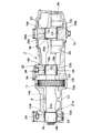
このバランサ装置7は、図2〜図5に示すように、オイルパン5の下面に固定されたハウジング8と、該ハウジング8の内部に回転自在に支持されて、機関前後方向に並行に配置された駆動側バランサシャフト9及び従動側バランサシャフト10と、該両バランサシャフト9,10の各ほぼ中央部側にそれぞれ設けられて、各歯部が互いに噛合したヘリカル型の駆動側ギア11及び従動側ギア12と、を備えている。
As shown in FIGS. 2 to 5, the
前記ハウジング8は、全体がアルミニウム合金材から形成され、オイルパン5側のロアーハウジング13と、該ロアーハウジング13の上部に配置されたアッパーハウジング14と、から構成され、この両ハウジング13,14は、複数のボルト15によって上下方向から締結固定されている。
The
前記ロアーハウジング13とアッパーハウジング14は、平面矩形状の狭幅部及び拡幅部に形成されて、上下から互いに対向する合わせ箇所の外周部に所定幅の枠状デッキ部13a、14aが形成されていると共に、拡幅部に前記枠状デッキ部13a、14aを横断する形で結合する軸受用突部である前後一対の平行な第1、第2横梁デッキ部13b、14b、13c、14cが一体に形成されている。
The
前記枠状デッキ部13a、14aの外周側の所定位置には、ハウジング8を前記ラダーフレーム4に取り付け固定するボルトのうちボルト40を挿通させる挿通孔を形成するための5つのボス部13g、14gが一体に形成されており、ボルト41を挿通させる挿通孔を形成するための1つのボス部14iはアッパーハウジング14側に形成されている。
Five
前記各ハウジング13,14の狭幅部の前端側には、前記各横梁デッキ部13b、14b、13c、14cと平行でかつ前記枠状デッキ部13a、14aと結合された短尺な第3横梁デッキ部13d、14dが一体に形成されている。
On the front end side of the narrow portion of each of the
前記第1〜第3横梁デッキ部13b、14b、13c、14c、13d、14dには、両ハウジング13,14を結合する前記各ボルト15が挿通する小径な8つのボルト挿通孔13h、14hがそれぞれ形成されている。
The first to third transverse
前記駆動側バランサシャフト9は、図2〜図5に示すように、先端軸9cの前端部にバランサスプロケット17が軸方向から螺着した固定用ボルト16によって固定されていると共に、このバランサスプロケット17と前記クランクスプロケット6との間に巻装された駆動チェーン18を介してクランクシャフト3からの回転力が伝達されるようになっている。これによって、前記両バランサシャフト9,10が、前記駆動側ギア11と従動側ギア12を介して互いに反対方向へ回転されるようになっている。なお、前記両シャフト9,10は、クランクシャフト3の1回転当たり2回転するように設定されている。
As shown in FIGS. 2 to 5, the drive-
前記駆動側バランサシャフト9は、図3〜図5に示すように、軸方向の前端側と中央部及び後端側にそれぞれ円柱状のジャーナル面9a、9b、9cが形成されていると共に、該各ジャーナル面9a〜9cが前記ロアーハウジング13とアッパーハウジング14の前記第1〜第3横梁デッキ部13b〜14dの対向する位置にそれぞれ形成された各3つの半円弧状の第1〜第3軸受凹溝19a,19b、20a,20b、21a,21bに滑り軸受であるプレーンベアリング22,23、24を介して回転自在に支持されている。
As shown in FIGS. 3 to 5, the drive-
駆動側バランサシャフト9の後側ジャーナル9bを挟んだ前後の対称位置には、半円形状の2つの第1、第2バランスウエイト25、26が一体に設けられている。この両バランスウエイト25,26は、同一形状でかつ同一の重量に形成されている。
Two semicircular first and
前記駆動側ギア11は、駆動側バランサシャフト9に圧入などによって固定されていると共に、図5に示すように、ロアーハウジング13の対向するスラスト壁13e、13fによって挟まれて軸方向への移動が規制されるようになっている。
The drive-
一方、前記従動側バランサシャフト10は、図3及び図4に示すように、その軸長が駆動側バランサシャフト9よりも短尺に形成されて、軸方向の前後端の2個所に形成されたジャーナル面10a、10bが前記両横梁デッキ部13b、14b、13c、14cの間に対向して形成された2つの半円弧状の第4、第5軸受凹溝27a,27b、28a,28bに滑り軸受であるプレーンベアリング29,30を介して回転自在に支持されている。
On the other hand, as shown in FIGS. 3 and 4, the driven-
なお、各ジャーナル面9a〜9c、10a、10bは、焼き入れしないで比較的軟質な金属材になっている。 Each journal surface 9a-9c, 10a, 10b is a relatively soft metal material without quenching.
また、従動側バランサシャフト10は、前記後部側のジャーナル面9bを挟んだ前後対称位置に半円弧状の2つの第1、第2バランスウエイト31,32が一体に設けられている。この両バランスウエイト31,32は、同一形状でかつ同一の重量に設定されている。
Further, the driven-
前記従動側ギア12は、従動側バランサシャフト10に圧入などによって固定されていると共に、図5に示すように、ロアーハウジング13に形成された溝内、つまり溝の対向するスラスト壁13e、13fにより挟まれて軸方向への移動が規制されるようになっている。
The driven
前記駆動側と従動側の各バランサシャフト9,10の各ジャーナル面9a〜9c、10a、10bは、それぞれの硬度が約330Hvに設定されている。
The journal surfaces 9a to 9c, 10a, and 10b of the drive-side and driven-
前記駆動側と従動側の第1〜第5プレーンベアリング22〜24、29,30は、図2〜図4に示すように、金属平板を上下に半割状に2分割形成されて、これら各半割部を前記各第1軸受凹溝19a〜21b、27a〜28bにそれぞれ嵌着固定して円筒状に形成している。この各プレーンベアリング22〜24、29,30は、それぞれの軸方向の幅がほぼ同一に設定されている。
The first to fifth
そして、前記各プレーンベアリング22〜24、29,30は、外周側の基材が圧延鋼板によって形成されていると共に、内周側の摺動面に硬質の合金層であるタングステンカーバイトカーボン(WCC)がコーティングされている。
Each of the
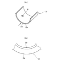
以下、図1A、Bに示すように、代表的な例として挙げた前記駆動側バランサシャフト9側のロアーハウジング13側に設けられたプレーンベアリング22について具体的に説明する。
Hereinafter, as shown in FIGS. 1A and 1B, a
すなわち、このプレーンベアリング22は、外周側の基材22aが硬度の高い圧延鋼板によって半円弧状に折曲形成されている一方、内周側の摺動面22bは前記WCCがコーティングされることによって合金層が形成されている。この摺動面22bの硬度は、前記駆動側バランサシャフト9のジャーナル面9aの硬度(約330HB)よりもかなり高い約1350HKに設定されている。前記プレーンベアリング22〜24、29、30を高硬度に設定した反面、各バランサシャフト9,10の各ジャーナル面9a〜9c、10a、10bは、前記プレーンベアリング22〜24、29、30と比較して低硬度(低ヤング率)に設定している。したがって、前記バランサシャフト9のベアリング接触面において弾性変形をする面積を増加させることにより、バランサシャフト9回転時のプレーンベアリング22〜24、29、30に対する負荷面圧を低減させることができる。
That is, the
なお、前記摺動面22bのコーティング肉厚は、従来の軟質材によって構成された場合よりも薄く設定されている。
Note that the coating thickness of the sliding
また、各ロアーハウジング13の枠状デッキ部13a及び各横梁デッキ部13b〜13dの上面には、図3に示すように、前記各プレーンベアリング22〜24、29,30に潤滑油を供給する潤滑油供給溝33が連続して形成されていると共に、前記各軸受凹溝19a〜21b、27a、27b、28a、28bの各内周面に前記潤滑油供給溝33と連通する油溝34がそれぞれ形成されている。
Further, as shown in FIG. 3, lubrication for supplying lubricating oil to the
また、前記各プレーンベアリング22〜24、29,30の幅方向のほぼ中央位置には、前記油溝34、34a内に供給された潤滑油を各摺動面22b〜24b、29b、30bと各ジャーナル面9a〜9c、10a、10bの外周面との間に導入させる2つの連通孔35が貫通形成されている。
In addition, the lubricating oil supplied into the
前記潤滑油供給溝33は、前記ロアーハウジング13にアッパーハウジング14が載置結合された状態で各デッキ部14a〜14dの下面と共に潤滑油供給通路が構成され、上流端に形成された油孔33aを介して図外のオイルポンプから潤滑油が供給されるようになっている。また、この潤滑油供給溝33は、前記各ボルト挿通孔13h付近ではこれを囲むように円形状に形成されている。
The lubricating
前記各油溝34は、各軸受凹溝19a〜21b、27a、27b、28a、28b間で円環状に形成されて、前記潤滑油供給溝33を介して互いに連通するようになっている。また、第2軸受凹溝20a、20bと第5軸受凹溝28a、28b側の油溝34aは、その形成位置が第2、第5プレーンベアリング23,30の各連通孔35の形成位置に合致するようになっている。
The
また、前記アッパーハウジング14の駆動側バランサシャフト9側の上壁部には、ハウジング8内に貯留されたオイルを前記オイルパン5内に戻す図外のオイル排出孔が形成されている。
In addition, an oil discharge hole (not shown) for returning the oil stored in the
したがって、このバランサ装置7によれば、機関が始動されてクランクシャフト3が回転駆動すると、クランクスプロケット6と駆動チェーン18及びバランサスプロケット17を介して駆動側バランサシャフト9が前記クランクシャフト3の2倍の速度で回転する。これによって、従動側バランサシャフト10が、駆動側ギア11と従動側ギア12の噛み合い回転伝達を経て駆動側バランサシャフト9と反対方向へ同速度で回転する。
Therefore, according to the
これにより、それぞれのバランスウエイト25、26、31、32も互いに反対方向へ回転しながらバランサシャフト9,10自体の左右の遠心力をキャンセルする。
As a result, the
このとき、ハウジング8は、オイルパン5内に滞留するオイルと各バランサシャフト8,9の干渉を防止し、該各バランサシャフト8,9が回転する際に発生する起振力を受けると同時に起振力を機関に伝達する。
At this time, the
このように、各バランサシャフト9,10の回転に伴い各バランスウエイト25,26、29,30が回転して起振力を内燃機関1に伝達することによって二次振動を抑制する。
As described above, the
そして、本実施形態では、前記各プレーンベアリング22〜24、29,30の摺動面22b〜24b、29b、30b全体を、硬度の高いタングステンカーバイトカーボン(WCC)によって形成したことから、前記各プレーンベアリング22〜24、29、30の摺動面22b〜24b、29b、30bの変形を抑制できる。
In the present embodiment, the entire sliding
すなわち、バランサ装置は、前記両バランサシャフト9,10に質量の大きなバランスウエイト25,26、29,30が設けられていることから、回転中における前記ジャーナル面9a〜9c、10a、10bから各プレーンベアリング22〜24、29,30の摺動面22b〜24b、29b、30bに対する当接荷重が極めて大きくなるといったバランサ装置特有の技術的課題を招いている。
That is, the balancer device is provided with
また、前記クランクシャフト3から駆動側バランサシャフト9への回転伝達手段が、本実施形態のように駆動チェーン18の場合には、前記バランサスプロケット17の取り付け部に最も近いジャーナル面9cとプレーンベアリング24の軸受に高張力が作用するため、過大なフリクションが発生する。したがって、前記従来のようにプレーンベアリング24の摺動面を柔らかな金属材にした場合は、前述と同じ技術的課題によって前記各プレーンベアリング22〜24、29、30の摺動面22b〜24b、29b、30bが変形して剥離するといった現象が発生する。
Further, when the rotation transmission means from the
そこで、本実施形態では、前記従来技術と異なり、前記各摺動面22b〜24b、29b、30bを硬度の高いWCCによって形成したことから、前記各プレーンベアリング22〜24、29,30の摺動面22b〜24b、29b、30bの変形を抑制できる。
Therefore, in the present embodiment, unlike the conventional technique, the sliding
これによって、前記各摺動面22b〜24b、29b、30bの剥離現象が十分に抑制されて耐久性の向上が図れる。
As a result, the peeling phenomenon of the sliding
しかも、前記各プレーンベアリング22〜24、29、30の摺動面22b〜24b、29b、30bの硬度化によって、前記駆動側バランサシャフト9と従動側バランサシャフト10の外径を、従来に比較して細くすることができる。これにより、前記各ジャーナル面9a〜9c、10a、10bと各摺動面22b〜24b、29b、30bとの間の粘性フリクション(面圧(許容面圧))を低減させることができる。この結果、フリクションがさらに低減して内燃機関の燃費を向上させることが可能になる。
In addition, the outer diameters of the drive-
さらに、前記各ジャーナル面9a〜9c、10a、10bと各摺動面22b〜24b、29b、30bとの間に、金属粉などのコンタミが入り込んだ場合には、これらコンタミを従来のように摺動部内に埋収するのではなく、互いに硬度の高い各ジャーナル面9a〜9c、10a、10bと各摺動面22b〜24b、29b、30bとの間で砕いてそのまま外部に排出する。このため、コンタミによる影響を緊急的に回避することが可能になる。
Further, when contaminants such as metal powder enter between the journal surfaces 9a to 9c, 10a and 10b and the sliding
また、前述のような、ジャーナル面9a〜9c、10a、10bと摺動面22b〜24b、29b、30bとの間の高面圧へ対応が可能になり、また、フリクションの大幅な低減効果によって、前記両バランサシャフト9,10の外径を細くすることができると共に、前記ジャーナル面と摺動面との軸方向の幅を小さくすることが可能になる。
In addition, it is possible to cope with the high surface pressure between the journal surfaces 9a to 9c, 10a, and 10b and the sliding
このように、両バランサシャフト9,10の細径化とジャーナル面の狭幅化によって各バランサシャフト9,10の軽量化が図れるため、両者間の前記フリクションをさらに低減できると共に、前記駆動側ギア11と従動側ギア12間の歯打ち音やスラスト方向の打音など、つまり振動と騒音(音振)の低減効果も得られる。
Thus, since the
すなわち、図7のグラフに示すように、前記軽量化(慣性質量の低下)によって両バランサシャフト9,10の回転軸を中心とした慣性モーメントが小さくなることから、前記音振の官能評点も良好になる。
That is, as shown in the graph of FIG. 7, the inertial moment about the rotating shafts of the
〔他の実施形態〕
前記実施形態では、前記摺動面22b〜24b、29b、30bを、WWCによって構成したが、他の合金層としては、例えばダイヤモンドライクカーボン(DLC)、クロムナイトライド(CrN)、窒化チタン(TiN)、窒化アルミチタン(TiAIN)、チタンカーボン(TiC)、アルミクロム窒化チタン(AICrN)などによって構成することも可能である。
[Other Embodiments]
In the said embodiment, although the said sliding
また、前記各ジャーナル面9a〜9c、10a、10bの硬度としては、330HB以下の170〜241HBとすることも可能であり、このような硬度の低いものを使用することによって、材料コストの低減化を図ることができると共に、コンタミによって形成されたバランサシャフト摺動面の摩耗溝に前記コンタミを一時的に収容することができる。 Further, the hardness of each of the journal surfaces 9a to 9c, 10a and 10b can be set to 170 to 241HB of 330HB or less, and by using such a low hardness, the material cost can be reduced. In addition, the contamination can be temporarily accommodated in the wear groove on the sliding surface of the balancer shaft formed by the contamination.
本発明のバランサ装置は、内燃機関の排気量などの大きさや仕様によって各バランサシャフト9,10の外径や長さ、またバランスウエイトなどの大きさが種々変更されたものにも適用できることは勿論である。
The balancer device of the present invention can be applied to
また、本発明の軸受構造は、例えば内燃機関のクランクシャフトのようなアンバランス部を有するシャフトの軸受構造に適用することもできる。 The bearing structure of the present invention can also be applied to a shaft bearing structure having an unbalanced portion such as a crankshaft of an internal combustion engine.
前記実施形態から把握される前記請求項以外の発明の技術的思想について以下に説明する。
〔請求項a〕請求項1または2に記載の内燃機関のバランサ装置において、
前記滑り軸受の摺動面に合金層をコーティングによって形成したことを特徴とする内燃機関のバランサ装置。
〔請求項b〕請求項aに記載の内燃機関のバランサ装置において、
前記滑り軸受の合金層を、タングステンカーバイトによって形成したことを特徴とする内燃機関のバランサ装置。
〔請求項c〕請求項aに記載の内燃機関のバランサ装置において、
前記滑り軸受の合金層を、ダイアモンドライクカーボンによって形成したことを特徴とする内燃機関のバランサ装置。
〔請求項d〕請求項aに記載の内燃機関のバランサ装置において、
前記滑り軸受の合金層を、クロムナイトライドによって形成したことを特徴とする内燃機関のバランサ装置。
〔請求項e〕請求項1または2に記載の内燃機関のバランサ装置において、
前記滑り軸受を半割円弧状の2つの分割片によって形成したことを特徴とする内燃機関のバランサ装置。
〔請求項f〕請求項1または2に記載の内燃機関のバランサ装置において、
前記両バランサシャフトの前記滑り軸受とのジャーナル面の硬度を約330Hvに設定する一方、前記滑り軸受の摺動面の硬度を、1350HK以上に設定したことを特徴とする内燃機関のバランサ装置。
The technical ideas of the invention other than the claims ascertained from the embodiment will be described below.
[A] A balancer device for an internal combustion engine according to claim 1 or 2,
A balancer device for an internal combustion engine, wherein an alloy layer is formed on a sliding surface of the sliding bearing by coating.
[B] A balancer device for an internal combustion engine according to claim a,
A balancer device for an internal combustion engine, wherein the sliding bearing alloy layer is formed of tungsten carbide.
[Claim c] A balancer device for an internal combustion engine according to claim a,
A balancer device for an internal combustion engine, wherein the alloy layer of the sliding bearing is formed of diamond-like carbon.
[Claim d] A balancer device for an internal combustion engine according to claim a,
A balancer device for an internal combustion engine, wherein the alloy layer of the slide bearing is formed of chromium nitride.
[Claim e] A balancer device for an internal combustion engine according to claim 1 or 2,
A balancer device for an internal combustion engine, wherein the slide bearing is formed by two half-arc-shaped divided pieces.
[Claim f] The balancer device for an internal combustion engine according to claim 1 or 2,
A balancer device for an internal combustion engine, wherein the hardness of the journal surface of the both balancer shafts with the sliding bearing is set to about 330 Hv, and the hardness of the sliding surface of the sliding bearing is set to 1350 HK or higher.
1・・・内燃機関
7…バランサ装置
8…ハウジング
9…駆動側バランサシャフト
9a〜9c・・・ジャーナル面
10…従動側バランサシャフト
10a・10b・・・ジャーナル面
11…駆動側ギア
12…従動側ギア
13…ロアーハウジング
19a、20a、21a…ロアーハウジング側の軸受凹溝
19b、20b、21b・・・アッパーハウジング側の軸受凹溝
25・26・・・駆動側バランサシャフトのバランスウエイト
22〜24・・・駆動側バランサシャフト側のプレーンベアリング
22b〜24b…摺動面
21a・21b…駆動側バランスウエイト
24a・24b…従動側バランスウエイト
27a・28a・・・ロアーハウジング側の軸受凹溝
27b・28b・・・アッパーハウジング側の軸受凹溝
29・30・・・従動側バランサシャフト側のプレーンベアリング
29b、30b…摺動面
31・32・・・従動側バランサシャフトのバランスウエイト
DESCRIPTION OF SYMBOLS 1 ...
Claims (3)
該駆動側バランサシャフトから回転力が伝達される従動側バランサシャフトと、
前記両バランサシャフトを内部に回転自在に収容したハウジングと、
前記駆動側バランサシャフトとハウジングとの間、並びに前記従動側バランサシャフトとハウジングとの間にそれぞれ設けられ、前記両バランサシャフトを回転自在に軸受する滑り軸受と、
を備え、
前記各滑り軸受の摺動面の硬度を、前記両バランサシャフトの前記滑り軸受に摺動するジャーナル面の硬度よりも高く設定したことを特徴とする内燃機関のバランサ装置。 A drive-side balancer shaft to which rotational force is transmitted from the crankshaft;
A driven side balancer shaft to which rotational force is transmitted from the drive side balancer shaft;
A housing which accommodates both the balancer shafts rotatably inside;
A sliding bearing provided between the drive-side balancer shaft and the housing, and between the driven-side balancer shaft and the housing, and rotatably bearing both the balancer shafts;
With
A balancer device for an internal combustion engine, characterized in that the hardness of the sliding surface of each sliding bearing is set higher than the hardness of the journal surface that slides on the sliding bearing of both balancer shafts.
該駆動側バランサシャフトから回転力が伝達され、外周にバランスウエイトを少なくとも1つ有する従動側バランサシャフトと、
前記両バランサシャフトを内部に回転自在に収容したハウジングと、
前記ハウジングに設けられ、前記両シャフトをそれぞれ回転自在に軸受する滑り軸受と、
を備え、
前記滑り軸受の摺動面の許容面圧を、前記両バランサシャフトの前記滑り軸受に摺動するジャーナル面の許容面圧よりも高くなるように設定したことを特徴とする内燃機関のバランサ装置。 A driving-side balancer shaft to which rotational force is transmitted from the crankshaft and having at least one balancer weight on the outer periphery;
A driven side balancer shaft to which rotational force is transmitted from the drive side balancer shaft and having at least one balance weight on the outer periphery;
A housing which accommodates both the balancer shafts rotatably inside;
A sliding bearing provided in the housing and rotatably bearing both shafts;
With
A balancer device for an internal combustion engine, characterized in that an allowable surface pressure of a sliding surface of the sliding bearing is set to be higher than an allowable surface pressure of a journal surface sliding on the sliding bearing of both balancer shafts.
を備え、
前記滑り軸受の硬度を、前記シャフトの前記滑り軸受が摺動するジャーナル面の硬度よりも高く設定したことを特徴とするシャフトの軸受構造。 A shaft provided with an unbalanced portion on the outer peripheral surface, a support member that supports the shaft, a slide bearing that is provided between the shaft and the support member and rotatably supports the shaft;
With
A shaft bearing structure characterized in that the hardness of the sliding bearing is set higher than the hardness of a journal surface on which the sliding bearing of the shaft slides.
Priority Applications (1)
| Application Number | Priority Date | Filing Date | Title |
|---|---|---|---|
| JP2011065513A JP2012202442A (en) | 2011-03-24 | 2011-03-24 | Balancer device for internal combustion engine and bearing structure of metal shaft |
Applications Claiming Priority (1)
| Application Number | Priority Date | Filing Date | Title |
|---|---|---|---|
| JP2011065513A JP2012202442A (en) | 2011-03-24 | 2011-03-24 | Balancer device for internal combustion engine and bearing structure of metal shaft |
Publications (1)
| Publication Number | Publication Date |
|---|---|
| JP2012202442A true JP2012202442A (en) | 2012-10-22 |
Family
ID=47183667
Family Applications (1)
| Application Number | Title | Priority Date | Filing Date |
|---|---|---|---|
| JP2011065513A Pending JP2012202442A (en) | 2011-03-24 | 2011-03-24 | Balancer device for internal combustion engine and bearing structure of metal shaft |
Country Status (1)
| Country | Link |
|---|---|
| JP (1) | JP2012202442A (en) |
Cited By (2)
| Publication number | Priority date | Publication date | Assignee | Title |
|---|---|---|---|---|
| KR20180052404A (en) * | 2016-11-10 | 2018-05-18 | (주)동보 | Balance shaft assembly |
| KR101862142B1 (en) * | 2016-11-10 | 2018-07-05 | (주)동보 | Balance shaft assembly |
Citations (8)
| Publication number | Priority date | Publication date | Assignee | Title |
|---|---|---|---|---|
| JPH0599228A (en) * | 1991-08-09 | 1993-04-20 | Toyota Motor Corp | Slide bearing for internal combustion engine |
| JP2001146919A (en) * | 1999-11-22 | 2001-05-29 | Canon Inc | Dynamic pressure bearing sleeve and method of manufacturing the same |
| JP2003013958A (en) * | 2001-06-26 | 2003-01-15 | Nissan Motor Co Ltd | Slide bearing and manufacturing method |
| JP2004138128A (en) * | 2002-10-16 | 2004-05-13 | Nissan Motor Co Ltd | Sliding member for automotive engine |
| JP2004347053A (en) * | 2003-05-23 | 2004-12-09 | Nissan Motor Co Ltd | Hard carbon coating sliding member |
| JP2005256062A (en) * | 2004-03-10 | 2005-09-22 | Sumitomo Denko Shoketsu Gokin Kk | Bearing for compressor |
| JP2008014351A (en) * | 2006-07-04 | 2008-01-24 | Hitachi Ltd | Engine balancer device |
| JP2010184954A (en) * | 2009-02-10 | 2010-08-26 | Fujifilm Corp | Sintered oilless bearing |
-
2011
- 2011-03-24 JP JP2011065513A patent/JP2012202442A/en active Pending
Patent Citations (8)
| Publication number | Priority date | Publication date | Assignee | Title |
|---|---|---|---|---|
| JPH0599228A (en) * | 1991-08-09 | 1993-04-20 | Toyota Motor Corp | Slide bearing for internal combustion engine |
| JP2001146919A (en) * | 1999-11-22 | 2001-05-29 | Canon Inc | Dynamic pressure bearing sleeve and method of manufacturing the same |
| JP2003013958A (en) * | 2001-06-26 | 2003-01-15 | Nissan Motor Co Ltd | Slide bearing and manufacturing method |
| JP2004138128A (en) * | 2002-10-16 | 2004-05-13 | Nissan Motor Co Ltd | Sliding member for automotive engine |
| JP2004347053A (en) * | 2003-05-23 | 2004-12-09 | Nissan Motor Co Ltd | Hard carbon coating sliding member |
| JP2005256062A (en) * | 2004-03-10 | 2005-09-22 | Sumitomo Denko Shoketsu Gokin Kk | Bearing for compressor |
| JP2008014351A (en) * | 2006-07-04 | 2008-01-24 | Hitachi Ltd | Engine balancer device |
| JP2010184954A (en) * | 2009-02-10 | 2010-08-26 | Fujifilm Corp | Sintered oilless bearing |
Cited By (3)
| Publication number | Priority date | Publication date | Assignee | Title |
|---|---|---|---|---|
| KR20180052404A (en) * | 2016-11-10 | 2018-05-18 | (주)동보 | Balance shaft assembly |
| KR101868436B1 (en) | 2016-11-10 | 2018-06-20 | (주)동보 | Balance shaft assembly |
| KR101862142B1 (en) * | 2016-11-10 | 2018-07-05 | (주)동보 | Balance shaft assembly |
Similar Documents
| Publication | Publication Date | Title |
|---|---|---|
| EP1081410B1 (en) | Balance shaft for engine balancing systems | |
| JP6165827B2 (en) | Crankshaft bearing device for internal combustion engine | |
| JP5968630B2 (en) | Vibration roller having synthetic excitation gear and method of operating the same | |
| JP5357132B2 (en) | Crankcase integrated balancer device | |
| JP4947527B2 (en) | Balancer device for internal combustion engine | |
| JP2006002852A (en) | Engine balancer device | |
| JP6224156B2 (en) | Crankshaft bearing device for internal combustion engine | |
| JP2010270783A (en) | Balancer-shaft-supporting bearing unit | |
| JP2012202442A (en) | Balancer device for internal combustion engine and bearing structure of metal shaft | |
| JP6395157B2 (en) | Balancer device for internal combustion engine | |
| JP2010261507A (en) | Bearing structure of eccentric shaft | |
| JP2008014351A (en) | Engine balancer device | |
| EP2159454B1 (en) | Idler gear and hub with coating | |
| JP2010230129A (en) | Balancer device of engine | |
| JP2013019517A (en) | Sliding bearing | |
| JP5226728B2 (en) | Balancer device for internal combustion engine | |
| JP6317786B2 (en) | Crankshaft bearing device for internal combustion engine | |
| JP2012057747A (en) | Balancer shaft | |
| JP6140020B2 (en) | Balancer device for internal combustion engine | |
| JP2016223477A (en) | Balancer device of internal combustion engine | |
| JP2001295891A (en) | Balancer device for engine | |
| EP1707769B1 (en) | Engine balancer | |
| US20190048936A1 (en) | Balancer device and balancer device for internal combustion engine | |
| WO2021187033A1 (en) | Balancer device and balancer device provided with oil pump | |
| JP4888814B2 (en) | Balancer device for internal combustion engine |
Legal Events
| Date | Code | Title | Description |
|---|---|---|---|
| A521 | Written amendment |
Free format text: JAPANESE INTERMEDIATE CODE: A523 Effective date: 20130826 |
|
| A621 | Written request for application examination |
Free format text: JAPANESE INTERMEDIATE CODE: A621 Effective date: 20130826 |
|
| A977 | Report on retrieval |
Free format text: JAPANESE INTERMEDIATE CODE: A971007 Effective date: 20140325 |
|
| A131 | Notification of reasons for refusal |
Free format text: JAPANESE INTERMEDIATE CODE: A131 Effective date: 20140401 |
|
| A521 | Written amendment |
Free format text: JAPANESE INTERMEDIATE CODE: A523 Effective date: 20140528 |
|
| A02 | Decision of refusal |
Free format text: JAPANESE INTERMEDIATE CODE: A02 Effective date: 20140708 |