JP4992338B2 - Method for manufacturing liquid container - Google Patents
Method for manufacturing liquid container Download PDFInfo
- Publication number
- JP4992338B2 JP4992338B2 JP2006220755A JP2006220755A JP4992338B2 JP 4992338 B2 JP4992338 B2 JP 4992338B2 JP 2006220755 A JP2006220755 A JP 2006220755A JP 2006220755 A JP2006220755 A JP 2006220755A JP 4992338 B2 JP4992338 B2 JP 4992338B2
- Authority
- JP
- Japan
- Prior art keywords
- ink
- liquid
- cartridge
- container
- wall surface
- Prior art date
- Legal status (The legal status is an assumption and is not a legal conclusion. Google has not performed a legal analysis and makes no representation as to the accuracy of the status listed.)
- Active
Links
Images


Landscapes
- Ink Jet (AREA)
Description
本発明は、例えばインクジェットプリンタ等に着脱可能なインクカートリッジとして好適な大気開放タイプの液体収容容器に液体を注入する液体注入方法及び液体収容容器に関する。 The present invention relates to a liquid injection method and a liquid storage container for injecting a liquid into an air release type liquid storage container suitable as an ink cartridge that can be attached to and detached from, for example, an ink jet printer.
インクジェットプリンタ等の液体消費装置に着脱可能なインクカートリッジ(液体収容容器)として、プリンタに着脱可能な容器本体内に、インクを収容するインク収容部(液体収容部)と、プリンタ側の印字ヘッド(液体噴射部)に接続されるインク供給部(液体供給部)と、インク収容部に貯留したインクをインク供給部に誘導するインク誘導路(液体誘導路)と、インク収容部内のインクの消費に伴って外部から大気をインク収容部内に導入する大気連通路と、を備える大気開放タイプのものが各種提案されている。 As an ink cartridge (liquid storage container) that can be attached to and detached from a liquid consuming apparatus such as an ink jet printer, an ink storage part (liquid storage part) that stores ink in a container body that can be attached to and detached from the printer, and a print head ( An ink supply section (liquid supply section) connected to the liquid ejection section), an ink guide path (liquid guide path) for guiding ink stored in the ink storage section to the ink supply section, and consumption of ink in the ink storage section Along with this, various types of open-air types including an atmospheric communication path for introducing atmospheric air into the ink storage portion from the outside have been proposed.
この種のインクカートリッジには、圧電振動体を有するセンサを液体収容部内の基準高さに配置したインク残量検出機構(液体検出部)が設けられているものがある(例えば、特許文献1参照)。このインク残量検出機構は、印刷処理によるインク消費で液体収容部のインク液面が基準高さまで下がって、インクの消費に伴って大気連通路から液体収容部に導入された外気がセンサの検出位置に到達すると、センサ周囲がインク液で満たされている場合とセンサ周囲に空気が接触している場合における振動特性(残留振動)の変化から、インクの液面が基準高さまで下がったことを検出するものである。 Some ink cartridges of this type are provided with an ink remaining amount detection mechanism (liquid detection unit) in which a sensor having a piezoelectric vibrator is arranged at a reference height in a liquid storage unit (see, for example, Patent Document 1). ). In this ink remaining amount detection mechanism, the ink level of the liquid storage unit drops to the reference height due to ink consumption by the printing process, and the outside air introduced into the liquid storage unit from the atmosphere communication path as the ink is consumed is detected by the sensor. When the position is reached, the ink level has dropped to the reference height due to changes in the vibration characteristics (residual vibration) when the sensor area is filled with ink and when the sensor is in contact with air. It is to detect.
すなわち、液体収容部に設けた圧電素子を有する圧電装置又はアクチュエータの振動部を振動させ、その後に振動部に残留する残留振動によって生ずる逆起電力を測定することで、共振周波数または逆起電力波形の振幅を検出して音響インピーダンスの変化を検出する。この検出信号がインクの残量表示やカートリッジ交換時期の通知に利用される。 That is, by vibrating the vibration part of a piezoelectric device or actuator having a piezoelectric element provided in the liquid storage part and then measuring the counter electromotive force generated by the residual vibration remaining in the vibration part, the resonance frequency or the counter electromotive force waveform is measured. The change of the acoustic impedance is detected by detecting the amplitude of. This detection signal is used to display the remaining amount of ink and to notify the cartridge replacement time.
ところで、インクカートリッジは、多数の部品から構成される高精度に形成された容器であるため、インクを消尽した時に、そのまま廃棄することは、有用な資源の廃棄となり、経済的に大きな損失となってしまう。そこで、使用済みのインクカートリッジにインクを再注入して再生することが望まれている。 By the way, since the ink cartridge is a container formed with a high precision composed of a large number of parts, if the ink is exhausted, discarding it as it is is a waste of useful resources, which is a large economic loss. End up. Therefore, it is desired to reinject ink into a used ink cartridge for reproduction.
ところが、従来のインクカートリッジは、その組立工程の途中に、インクの注入工程を組み込んでおり、インクカートリッジの組立完了後は、同様のインク注入方法が利用できない場合が多い。そこで、新品のインクカートリッジを組み立てる際のインク注入方法は使わずに、インクの充填を実現するインク注入方法の開発が必要となる。 However, conventional ink cartridges incorporate an ink injection process in the middle of the assembly process, and the same ink injection method cannot be used in many cases after the completion of the ink cartridge assembly. Therefore, it is necessary to develop an ink injection method that realizes ink filling without using an ink injection method for assembling a new ink cartridge.
しかし、最近のインクカートリッジは、インク収容室とインク供給部とを連通するインク誘導路に、インク供給部へ供給するインク圧を調整すると共にインク供給部側からの逆流を防止する逆止弁としても機能する差圧弁が設けられたり、あるいはインクの残量を検出するインク残量検出機構が設けられたりして、高性能化されている。更には、インク収容室や大気連通路の構造も複雑化している。 However, recent ink cartridges have a check valve that adjusts the ink pressure supplied to the ink supply unit and prevents backflow from the ink supply unit side in an ink guide path that connects the ink storage chamber and the ink supply unit. In other words, a high-performance differential pressure valve is provided, or an ink remaining amount detection mechanism for detecting the remaining amount of ink is provided. Furthermore, the structure of the ink storage chamber and the atmosphere communication path is also complicated.
そのため、インク注入のために、不用意に容器本体を加工すると、インクを注入した際に、インク収容室以外の部分にインクが漏れたり、インク注入時に混入する気泡の為に当初の機能が損なわれたりして、再生不良を招く虞がある。
特に、注入されたインクの液中を浮遊する気泡がインク残量検出機構のセンサ表面に付着すると、付着した気泡が残留振動の変化を招いて、インクの有無が正確に検出できずインクの液面が下がったものと誤検出されてしまう虞がある。
For this reason, if the container body is carelessly processed for ink injection, when the ink is injected, the ink leaks to a part other than the ink storage chamber, or the original function is impaired due to bubbles mixed during ink injection. May result in poor reproduction.
In particular, when bubbles floating in the injected ink liquid adhere to the sensor surface of the ink remaining amount detection mechanism, the adhering bubbles cause a change in residual vibration, and the presence or absence of ink cannot be detected accurately, and the ink liquid. There is a risk of erroneous detection that the surface is lowered.
従って、本発明の目的は上記課題を解消することに係り、液体収容容器の諸機能を損なうことなく液体を注入することができる液体収容容器の製造方法を提供することである。 Accordingly, an object of the present invention is to provide a method of manufacturing a liquid container capable of injecting a liquid without relates to solve the above problems, impairing the functions of the liquid container.
液体消費装置に着脱可能な液体収容容器を製造する方法であって、
(a)液体収容部と、前記液体消費装置に接続される液体供給部と、前記液体収容部に
貯留された液体を前記液体供給部に誘導するための液体誘導路と、前記液体収容部内の液
体の消費に伴って外部から大気を前記液体収容部内に導入するための、一部がフィルムで形成された大気連通路と、を備えると共に、前記液体収容部に、第1の内壁面と、該第1の内壁面に交わり、前記第1の内壁面から前記液体誘導路側とは反対側である前記液体収容部側に延びる第2の内壁面と、該第2の内壁面に近接した前記第1の内壁面に穿設されて前記液体収容部を前記液体誘導路に連通させる液体収容部出口と、を備える容器を用意する工程と、
(b)前記液体収容部に連通する注入口を前記大気連通路に形成する工程と、
(c)前記注入口から所定量の液体を注入する工程と、
(d)前記液体を注入する工程の終了後に前記注入口を封止する工程と、
を含み、
前記工程(b)において、前記大気連通路を形成するフィルムに孔を開けて前記注入口を形成することを特徴とする液体収容容器の製造方法により達成される。
A method for producing a liquid container detachable from a liquid consumption device,
(A) a liquid storage unit, a liquid supply unit connected to the liquid consumption device, a liquid guide path for guiding the liquid stored in the liquid storage unit to the liquid supply unit, and the liquid storage unit A part of the air communication passage formed of a film for introducing the air into the liquid container from the outside as the liquid is consumed, and the liquid container having a first inner wall surface; A second inner wall surface that intersects the first inner wall surface and extends from the first inner wall surface to the liquid container side opposite to the liquid guiding path side; and the second inner wall surface that is close to the second inner wall surface Preparing a container comprising: a liquid storage unit outlet formed in the first inner wall surface and communicating the liquid storage unit with the liquid guide path;
(B) forming an inlet port communicating with the liquid container in the atmosphere communication path;
(C) injecting a predetermined amount of liquid from the injection port;
(D) sealing the inlet after completion of the step of injecting the liquid;
Including
In the step (b), this is achieved by a method for manufacturing a liquid container, wherein the film forming the air communication passage is perforated to form the inlet .
また、本発明の上記目的は、液体消費装置に装着される液体収容容器を製造する方法であって、液体収容部と、前記液体消費装置に接続される液体供給部と、前記液体収容部に貯留された液体を前記液体供給部に誘導するための液体誘導路と、前記液体収容部内の液体の消費に伴って外部から大気を前記液体収容部内に導入するための大気連通路と、を備えると共に、前記液体収容部に、第1の内壁面と、該第1の内壁面に交わって互いに対向する一対の内壁面と、前記一対の内壁面の間における前記第1の内壁面に穿設されて前記液体収容部を前記液体誘導路に連通させる液体収容部出口と、を備える容器を用意する工程と、
前記液体収容部に連通する注入口を前記大気連通路に形成する工程と、
前記注入口から所定量の液体を注入する工程と、
前記液体を注入する工程の終了後に前記注入口を封止する工程と、
を含む液体収容容器の製造方法により達成される。
The above-described object of the present invention is a method for manufacturing a liquid container to be mounted on a liquid consuming device, wherein the liquid container includes a liquid container, a liquid supply unit connected to the liquid consuming device, and the liquid container. comprising a liquid guide path for guiding the stored liquid to the liquid supply portion, and the atmosphere communication passage for introducing air into the liquid containing portion from the outside with the consumption of the liquid in the liquid containing portion together with, in the liquid storage portion, bored a first inner wall surface, a pair of inner wall surfaces opposed to each other intersect with the inner wall surface of the first, the first inner wall surface between the pair of inner wall surfaces And a step of preparing a container including a liquid storage unit outlet that allows the liquid storage unit to communicate with the liquid guide path;
Forming an inlet communicating with the liquid container in the atmosphere communication path;
Injecting a predetermined amount of liquid from the injection port;
Sealing the inlet after completion of the step of injecting the liquid;
It is achieved by a method for manufacturing a liquid container including
これらの構成の液体収容容器の製造方法によれば、液体の注入のために容器に実施する加工は、液体を注入するための注入口を開口させることと、液体の注入後に、前記注入口を封止する加工で、いずれも簡単な加工となる。使用済みの液体収容容器に液体を注入する際に、液体収容容器への加工が少なくて済み、しかも、その液体収容容器の諸機能を損なうことなく液体を注入することができ、使用済みの液体収容容器を安価に利用することができる。
According to the manufacturing method of the liquid container having these configurations, the processing performed on the container for injecting the liquid includes opening the inlet for injecting the liquid, and after injecting the liquid, The process of sealing is a simple process. When injecting a liquid into a used liquid storage container , the processing into the liquid storage container can be reduced, and the liquid can be injected without impairing the functions of the liquid storage container. The storage container can be used at low cost.
更に、本発明の上記目的は、液体消費装置に着脱可能な容器本体内に、液体収容部と、前記液体消費装置に接続される液体供給部と、前記液体収容部に貯留した液体を前記液体供給部に誘導する液体誘導路と、前記液体収容部内の液体の消費に伴って外部から大気を前記液体収容部内に導入する大気連通路と、を備えると共に、
前記液体収容部には、第1の内壁面と、該第1の内壁面に交わる第2の内壁面と、該第2の内壁面に近接した前記第1の内壁面に穿設されて前記液体収容部を前記液体誘導路に連通させる液体収容部出口と、を備える大気開放タイプの液体収容容器に対し、
前記液体収容部に連通する注入口を前記大気連通路に形成し、前記注入口から所定量の液体を注入し、前記液体を注入した後に前記注入口を封止して成る液体収容容器により達成される。
Furthermore, the object of the present invention is to provide a liquid container, a liquid supply unit connected to the liquid consumer, and a liquid stored in the liquid container in the container body detachable from the liquid consumer. A liquid guiding path for guiding to the supply unit, and an air communication path for introducing air into the liquid storage unit from the outside as the liquid in the liquid storage unit is consumed.
The liquid container is provided with a first inner wall surface, a second inner wall surface intersecting the first inner wall surface, and the first inner wall surface proximate to the second inner wall surface. A liquid storage unit outlet that communicates the liquid storage unit with the liquid guide path, and an open air type liquid storage container,
An injection port communicating with the liquid storage part is formed in the atmosphere communication path, a predetermined amount of liquid is injected from the injection port, and the injection port is sealed after the liquid is injected. Is done.
また、本発明の上記目的は、液体消費装置に装着される容器本体内に、液体収容部と、前記液体消費装置に接続される液体供給部と、前記液体収容部に貯留した液体を前記液体供給部に誘導する液体誘導路と、前記液体収容部内の液体の消費に伴って外部から大気を前記液体収容部内に導入する大気連通路と、を備えると共に、
前記液体収容部には、第1の内壁面と、該第1の内壁面に交わって互いに対向する一対の内壁面と、前記一対の内壁面の間における前記第1の内壁面に穿設されて前記液体収容部を前記液体誘導路に連通させる液体収容部出口と、を備える大気開放タイプの液体収容容器に対し、
前記液体収容部に連通する注入口を前記大気連通路に形成し、前記注入口から所定量の液体を注入し、前記液体を注入した後に前記注入口を封止して成る液体収容容器により達成される。
Further, the above object of the present invention is to provide a liquid container, a liquid supply unit connected to the liquid consumer, and a liquid stored in the liquid container in the container body attached to the liquid consumer. A liquid guiding path for guiding to the supply unit, and an air communication path for introducing air into the liquid storage unit from the outside as the liquid in the liquid storage unit is consumed.
The liquid container is provided with a first inner wall surface, a pair of inner wall surfaces crossing the first inner wall surface and facing each other, and the first inner wall surface between the pair of inner wall surfaces. A liquid storage unit outlet that communicates the liquid storage unit with the liquid guide path, and an open air type liquid storage container,
An injection port communicating with the liquid storage part is formed in the atmosphere communication path, a predetermined amount of liquid is injected from the injection port, and the injection port is sealed after the liquid is injected. Is done.
これらの構成の液体収容容器によれば、液体収容容器は、新規の製造された液体収容容器と同様の状態に液体が充填されていて、新規の製造された未使用の液体収容容器と同様に容器内の諸機能が働き、新規の製造された未使用の液体収容容器と同様の使い勝手を得ることができ、容器としての製品寿命が延びるため、資源の節約、環境汚染の防止に貢献することができる。
また、コストが安価で、安価に提供できるため、液体消費装置の運用コストの低下にも貢献する。
According to the liquid container of these configurations, the liquid container is filled with the liquid in the same state as the newly manufactured liquid container, and is similar to the newly manufactured unused liquid container. Functions in the container work and can be used as a newly manufactured unused liquid container, and the product life as a container is extended, contributing to resource conservation and prevention of environmental pollution. Can do.
In addition, since the cost is low and it can be provided at a low cost, it contributes to a reduction in the operating cost of the liquid consuming apparatus.
尚、上記構成の液体収容容器において、前記液体収容部出口が、前記液体収容部に収容される液体によって前記第1の内壁面と前記第2の内壁面との隅部に形成されるメニスカスより内側の領域に設けられることが望ましい。 In the liquid container having the above-described configuration, the liquid container outlet is formed by a meniscus formed at the corner between the first inner wall surface and the second inner wall surface by the liquid stored in the liquid container. It is desirable to be provided in the inner region.
このような構成によれば、液体収容部出口が、液体収容部に収容される液体の物性(特に粘度等)により異なった形状・大きさで隅部に形成されるメニスカスの内側に配置される。そこで、表面張力により隅部に集められる液体が確実に抜き取り可能となり、収容液体に応じた最適な排出効果が得られる。 According to such a configuration, the liquid storage unit outlet is disposed inside the meniscus formed at the corner with a different shape and size depending on the physical properties (particularly viscosity) of the liquid stored in the liquid storage unit. . Therefore, the liquid collected at the corners by the surface tension can be surely extracted, and an optimal discharge effect corresponding to the stored liquid can be obtained.
また、上記構成の液体収容容器において、前記液体収容部出口の流入液上流側には、液流入間隙を隔てて対向壁が設けられることが望ましい。
このような構成によれば、使用中の容器本体が液体消費装置から脱着され、手によって振られ、液体収容部内の気液が攪拌された場合であっても、攪拌により流動する気液の殆どが対向壁に衝突し、衝突により液体収容部出口に直接的に加わる衝撃が低減され、液体収容部出口からの気泡流出を効果的に防止できる。
In the liquid container having the above-described configuration, it is preferable that an opposing wall is provided on the upstream side of the inflowing liquid at the outlet of the liquid storing part with a liquid inflow gap therebetween.
According to such a configuration, even when the container main body in use is detached from the liquid consuming apparatus, shaken by hand, and the gas-liquid in the liquid container is stirred, most of the gas-liquid flowing by stirring Impacts the opposing wall, and the impact directly applied to the outlet of the liquid container due to the collision is reduced, so that the outflow of bubbles from the outlet of the liquid container can be effectively prevented.
また、上記構成の液体収容容器において、前記第1の内壁面が、前記液体消費装置に前記容器本体を装着した姿勢における前記液体収容部の底面であることが望ましい。
このような構成によれば、第1の内壁面が液体収容部の底面となることで、残液の最も残り易い面が第1の内壁面となる。これにより、最後の残液まで液体収容部出口へ誘導でき、残液の抜き取り性を向上させることができる。また、液体の掃け性も向上する。
In the liquid container having the above-described configuration, it is desirable that the first inner wall surface is a bottom surface of the liquid container in a posture in which the container body is mounted on the liquid consuming device.
According to such a configuration, since the first inner wall surface becomes the bottom surface of the liquid storage portion, the surface on which the remaining liquid is most likely to remain becomes the first inner wall surface. Thereby, it can guide to a liquid storage part exit to the last residual liquid, and can improve the extractability of a residual liquid. In addition, the sweepability of the liquid is improved.
また、上記構成の液体収容容器において、前記液体収容部出口が、前記液体収容部に貯留される液体によってメニスカスが形成される程度に小さい丸穴であることが望ましい。
このような構成によれば、液体収容部出口に表面張力によって強いメニスカスが形成され、液体収容部内の残液が少なくなり、かつ手によって振られ、液体収容部内の気液が攪拌された場合であっても、液体収容部出口に形成されたメニスカスが障壁となり、液体収容部出口からの気泡流出を防止できる。
In the liquid container having the above-described configuration, it is preferable that the liquid container outlet is a round hole small enough to form a meniscus with the liquid stored in the liquid container.
According to such a configuration, a strong meniscus is formed by the surface tension at the outlet of the liquid storage part, the residual liquid in the liquid storage part is reduced, and the liquid is shaken by hand, and the gas-liquid in the liquid storage part is stirred. Even if it exists, the meniscus formed in the liquid accommodating part exit becomes a barrier, and the bubble outflow from the liquid accommodating part outlet can be prevented.
また、上記構成の液体収容容器において、前記液体誘導路には、当該液体誘導路への気体の流入を検知することで前記液体収容部の液体が消尽されたことを検出する液体検出部が設けられることが望ましい。
このような構成によれば、液体誘導路に液体検出部が設けられる場合であっても、液体掃けの悪さや使用中の気泡による誤検出を防止でき、液体検出部の検出精度を向上させることができる。
In the liquid container having the above-described configuration, the liquid guide path is provided with a liquid detection unit that detects that the liquid in the liquid container is exhausted by detecting the inflow of gas into the liquid guide path. It is desirable that
According to such a configuration, even when a liquid detection unit is provided in the liquid guide path, it is possible to prevent poor detection of liquid and erroneous detection due to bubbles in use, and improve the detection accuracy of the liquid detection unit. Can do.
以下、本発明に係る液体注入方法及び液体収容容器の好適な実施の形態について、図面を参照して詳細に説明する。以下の実施形態では、液体収容容器の一例として、液体噴射装置の一例であるインクジェット式記録装置(プリンタ)に装着されるインクカートリッジを挙げて説明する。 Hereinafter, preferred embodiments of a liquid injection method and a liquid container according to the present invention will be described in detail with reference to the drawings. In the following embodiments, as an example of the liquid container, an ink cartridge mounted on an ink jet recording apparatus (printer) that is an example of a liquid ejecting apparatus will be described.
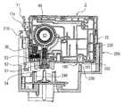
図1は本発明に係る液体収容容器の一実施形態としてのインクカートリッジの外観斜視図であり、図2は本実施形態のインクカートリッジを図1とは逆の角度からみた外観斜視図である。図3は本実施形態のインクカートリッジの分解斜視図、図4は本実施形態のインクカートリッジを図3とは逆の角度からみた分解斜視図である。図5は本実施形態のインクカートリッジをキャリッジに取り付けた状態を示す図であり、図6はキャリッジへの取付直前の状態を示す断面図、図7はキャリッジへの取付直後の状態を示す断面図である。 FIG. 1 is an external perspective view of an ink cartridge as an embodiment of a liquid container according to the present invention, and FIG. 2 is an external perspective view of the ink cartridge of this embodiment as viewed from the opposite angle to FIG. FIG. 3 is an exploded perspective view of the ink cartridge of the present embodiment, and FIG. 4 is an exploded perspective view of the ink cartridge of the present embodiment as viewed from the opposite angle to FIG. FIG. 5 is a view showing a state in which the ink cartridge of the present embodiment is attached to the carriage, FIG. 6 is a cross-sectional view showing a state immediately before attachment to the carriage, and FIG. 7 is a cross-sectional view showing a state immediately after attachment to the carriage. It is.
本実施形態のインクカートリッジ1は、図1及び図2に示すように、略直方体形状を有し、内部に設けられたインク収容室(液体収容室)にインク(液体)Iを貯留・収納する液体収容容器である。インクカートリッジ1は、液体消費装置の一例としてのインクジェット式記録装置のキャリッジ200に装着され、当該インクジェット式記録装置にインクを供給する(図5参照)。
As shown in FIGS. 1 and 2, the
インクカートリッジ1の外観的特徴について説明すると、図1及び図2に示すように、インクカートリッジ1は、フラットな上面1aを有し、上面1aに対向する底面1bにインクジェット式記録装置に接続されてインクを供給するインク供給部(液体供給部)50が設けられている。また、底面1bには、インクカートリッジ1内部に大気を導入する大気開放孔100が開口している。すなわち、インクカートリッジ1は、大気開放孔100から空気を導入しつつインク供給部50からインクを供給する大気開放型のインクカートリッジである。
The appearance characteristics of the
本実施形態では、大気開放孔100は、図6に示すように、底面1bに底面側から上面側に向けて開口した略円筒形状の凹部101と、凹部101の内周面に開口した小孔102とを有している。小穴102は、後述の大気連通路に連通しており、この小穴102を介して大気が後述の最上流の上部インク収容室370に導入される。
In the present embodiment, as shown in FIG. 6, the
大気開放孔100の凹部101は、キャリッジ200に形成された突起230を受け入れるような深さに構成されている。この突起230は、大気開放孔100を気密に閉塞する閉塞手段としての封止フィルム90の剥がし忘れを防止するための剥離忘れ防止突起である。すなわち、封止フィルム90が貼り付けられた状態では、大気開放孔100内に突起230が挿入されないため、インクカートリッジ1がキャリッジ200に取り付けられない。これによりユーザが、大気開放孔100上に封止フィルム90が貼り付けたままキャリッジ200にインクカートリッジ1を取り付けようとしても取り付けられないようにすることにより、インクカートリッジ1の装着時には確実に封止フィルム90を剥がすように促すことができる。
The
また、図1に示すように、インクカートリッジ1の上面1aの一つの短辺側に隣り合う狭側面1cには、インクカートリッジ1が誤った位置に装着されることを防ぐための誤挿入防止突起22が形成されている。受け手となるキャリッジ200側には、図5に示すように、誤挿入防止突起22と対応する凹凸220が形成されており、インクカートリッジ1は誤挿入防止突起22と凹凸220とが干渉しない場合のみキャリッジ200に装着される。誤挿入防止突起22は、インクの種類毎に異なる形状を有し、受け手となるキャリッジ200側の凹凸220も対応するインクの種類に応じた形状を有している。したがって、図5に示すように、キャリッジ200が複数のインクカートリッジを装着可能な場合でも、誤った位置にインクカートリッジを装着することがない。
Further, as shown in FIG. 1, an erroneous insertion prevention protrusion for preventing the
また、図2に示すように、インクカートリッジ1の狭側面1cと対向する狭側面1dには、係合レバー11が設けられている。この係合レバー11は、キャリッジ200への装着時にキャリッジ200に形成された凹部210と係合する突起11aが形成されており、係合レバー11が撓みつつ突起11aと凹部210が係合することによりキャリッジ200に対してインクカートリッジ1が位置固定される。
Further, as shown in FIG. 2, an
また、係合レバー11の下方には、回路基板34が設けられている。この回路基板34上には、複数の電極端子34aが形成されており、これら電極端子34aがキャリッジ200に設けられた電極部材(不図示)と接触することにより、インクカートリッジ1が電気的にインクジェット式記録装置と接続される。回路基板34には、データ書換可能な不揮発性メモリが設けられており、インクカートリッジ1に関する各種情報やインクジェット式記録装置のインク使用情報等が記憶される。また、回路基板34の裏側には、インクカートリッジ1内のインク残量を、残留振動を利用して検出する液体残量センサ(液体検出部)31(図3または図4参照のこと)が設けられている。以下の説明では、液体残量センサ31と回路基板34とを合わせてインクエンドセンサ30と呼称することとする。
A
また、インクカートリッジ1の上面1aには、図1に示すように、インクカートリッジの中身を示すラベル60aが貼り付けられている。このラベル60aは、広側面1fを覆う外表面フィルム60の端部が上面1aにまでまたがって貼り付けられることによって形成されている。
As shown in FIG. 1, a
また、図1及び図2に示すように、インクカートリッジ1の上面1aの2つの長辺側に隣り合う広側面1e,1fは、フラットな面形状とされている。以下の説明では、便宜上、広側面1eの側を正面側、広側面1fの側を背面側、狭側面1cの側を右側面側、そして狭側面1dの側を左側面側として説明する。
As shown in FIGS. 1 and 2, the
次に、図3及び図4を参照しながら、インクカートリッジ1を構成する各部について説明する。
インクカートリッジ1は、容器本体であるカートリッジ本体10と、カートリッジ本体10の正面側を覆う蓋部材20とを有している。
Next, each part constituting the
The
カートリッジ本体10は、その正面側には様々な形状を有するリブ10aが形成されており、これらのリブ10aが仕切を為して、インクIが充填される複数のインク収容室(液体収容室)、インクIは充填されない未充填室、後述の大気連通路150の途中に位置する空気室などを、内部に区画形成する。
The
カートリッジ本体10と蓋部材20との間には、カートリッジ本体10の正面側を覆うフィルム80が設けられており、このフィルム80によってリブ、凹部、溝の上面が塞がれて複数の流路やインク収容室、未充填室、空気室が形成される。
A
またカートリッジ本体10の背面側には、差圧弁40を収容する凹部としての差圧弁収容室40aと気液分離フィルタ70を構成する凹部としての気液分離室70aとが形成されている。
差圧弁収容室40aには、バルブ部材41とバネ42とバネ座43とが収納されて差圧弁40を構成している。差圧弁40は、下流側のインク供給部50と上流側のインク収容室との間に配置されており、上流側に対して下流側を減圧することで、インク供給部50に供給されるインクIが負圧となるように構成されている。
Further, on the back side of the
A
気液分離室70aの上面には、気液分離室70aの中央部近傍に設けられた外周を囲む土手70bに沿って気液分離膜71が貼着されている。この気液分離膜71は、気体を通過させるとともに液体を通過不可能に遮断する素材であり、全体で気液分離フィルタ70を構成している。気液分離フィルタ70は、大気開放孔100とインク収容室とを結ぶ大気連通路150内に設けられており、インク収容室のインクIが大気連通路150を経て大気開放孔100から流出しないようにするためのものである。
A gas-
カートリッジ本体10の背面側には、差圧弁収容室40aと気液分離室70a以外にも複数の溝10bが刻まれている。これらの溝10bは、差圧弁40と気液分離フィルタ70が構成された状態で外表面を外表面フィルム60が覆うことにより各溝10bの開口部が塞がれ、大気連通路150やインク誘導路(液体誘導路)が形成される。
In addition to the differential pressure
カートリッジ本体10の右側面側には、図4に示すように、インクエンドセンサ30を構成する各部材を収納する凹部としてセンサ室30aが形成されている。このセンサ室30aには、液体残量センサ31と、液体残量センサ31をセンサ室30aの内壁面に押しつけて固定する圧縮バネ32とが収納される。また、センサ室30aの開口部はカバー部材33によって覆われ、このカバー部材33の外表面33a上に回路基板34が固定される。液体残量センサ31のセンシング部材は回路基板34と接続されている。
As shown in FIG. 4, a
液体残量センサ31は、インク収容室からインク供給部50との間のインク誘導路の一部を形成するキャビティと、このキャビティの壁面の一部を形成する振動板と、この振動板上に振動を印加させる圧電素子(圧電アクチュエータ)とを備えて、前記振動板に振動を印加した際の残留振動から前記インク誘導路内におけるインクIの有無を検出する。この液体残量センサ31は、インクIと気体(インクに混入した気泡B)との間での残留振動の振幅、周波数等の違いを検出して、カートリッジ本体10内におけるインクIの有無を検出する。
具体的には、カートリッジ本体10内のインク収容室のインクIが消尽されて、インク収容室内に導入された大気がインク誘導路を伝って、液体残量センサ31のキャビティ内に進入すると、その時の残留振動の振幅や周波数の変化から、その旨を検知し、インクエンドを示す電気信号を出力する。
The liquid remaining
Specifically, when the ink I in the ink storage chamber in the cartridge
カートリッジ本体10の底面側には、先ほど説明したインク供給部50と大気開放孔100以外に、図4に示すように、インク注入時に真空引き手段を介してインクカートリッジ1内部から空気を吸い出して減圧に用いられる減圧孔110と、インク収容室からインク供給部50に至るインク誘導路を構成する凹部95aと、インクエンドセンサ30の下方に設けられたバッファ室30bとが形成されている。
On the bottom surface side of the
インク供給部50、大気開放孔100、減圧孔110、凹部95a、及びバッファ室30bは、インクカートリッジ製造直後には、全てそれぞれ封止フィルム54,90,98,95,35によってそれぞれの開口部が封止された状態となっている。このうち、大気開放孔100を封止する封止フィルム90は、インクカートリッジをインクジェット式記録装置に装着して使用状態とする前にユーザによって剥離される。これにより、大気開放孔100が外部に露出し、インクカートリッジ1内部のインク収容室が大気連通路150を介して外気と連通する。
The
また、インク供給部50の外表面に貼り付けられた封止フィルム35は、図6及び図7に示すように、インクジェット式記録装置への装着時にインクジェット式記録装置側のインク供給針240によって破られるように構成されている。
Further, as shown in FIGS. 6 and 7, the sealing
インク供給部50の内部には、図6及び図7に示すように、装着時にインク供給針の240の外表面に押しつけられる環状のシール部材51と、プリンタに装着されていない場合はシール部材51と当接してインク供給部50を閉塞するバネ座52と、バネ座52をシール部材51の当接方向に付勢する圧縮バネ53とを備えている。
As shown in FIGS. 6 and 7, the
図6及び図7に示すように、インク供給針240がインク供給部50内に挿入されると、シール部材51の内周とインク供給針240の外周がシールされ、インク供給部50とインク供給針240との間の隙間が液密に封止される。また、インク供給針51の先端がバネ座52と当接し、バネ座52を上に押し上げ、バネ座52とシール部材51のシールが解除されることにより、インク供給部50からインク供給針240にインクが供給可能となる。
6 and 7, when the
次に、図8〜図12を参照しながら、本実施形態のインクカートリッジ1の内部構造について説明する。
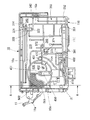
図8は本実施形態のインクカートリッジ1のカートリッジ本体10を正面側から見た図であり、図9は本実施形態のインクカートリッジ1のカートリッジ本体10を背面側から見た図であり、図10の(a)は図8の簡略模式図であり、図10の(b)は図9の簡略模式図であり、図11は図8のA−A断面図である。また、図12は図8に示した流路の一部拡大斜視図である。
Next, the internal structure of the
8 is a view of the cartridge
本実施形態のインクカートリッジ1では、インクIが充填される主なインク収容室として、上下2つに分断された上部インク収容室370及び下部インク収容室390と、これらの上下のインク収容室に挟まれるように位置するバッファ室430とからなる3つのインク収容室が、カートリッジ本体10の正面側に形成されている(図10参照)。
また、カートリッジ本体10の背面側には、インクIの消費量に応じて、大気を最上流のインク収容室である上部インク収容室370に導入する大気連通路150が形成されている。
In the
Further, an
インク収容室370,390及びバッファ室430は、リブ10aにより区分されている。そして、本実施形態の場合、これらの各インク収容室は、水平方向に延在して収容室の底壁となるリブ10aの一部に、下方に窪ませた形状の窪み374,394,434が形成されている。
The
窪み374は、上部インク収容室370のリブ10aによる底壁375の一部を下方に窪ませたものである。窪み394は、下部インク収容室390のリブ10aによる底壁395と壁面の膨出部によりカートリッジ厚さ方向に窪ませたものである。窪み434は、バッファ室430のリブ10aによる底壁435の一部を下方に窪ませたものである。
The
そして、各窪み374,394,434の底部又はその付近には、インク誘導路380、上流側インクエンドセンサ連絡流路400及びインク誘導路440に連通するインク排出口371,311,432が設けられている。
インク排出口371,432は、各インク収容室の壁面をカートリッジ本体10の厚さ方向に貫通した貫通孔である。また、インク排出口311は、底壁395を下方に貫通した貫通穴である。
In addition,
The
インク誘導路380は、一端が上部インク収容室370のインク排出口371に連通すると共に、他端が下部インク収容室390に設けられたインク流入口391に連通しており、上部インク収容室370のインクIを下部インク収容室390に誘導する連絡流路となっている。このインク誘導路380は、上部インク収容室370のインク排出口371から鉛直下方に延びた形態で設けられており、連絡流路内でのインクIの流れ方向が上から下への降下流となる降下型接続で一対の液体収容室370,390相互を接続している。
One end of the
インク誘導路420は、一端が下部インク収容室390の下流に位置する液体残量センサ31内のキャビティのインク排出口312に連通すると共に、他端がバッファ室430に設けられたインク流入口431に連通しており、下部インク収容室390のインクIをバッファ室430に誘導する。このインク誘導路420は、液体残量センサ31内のキャビティのインク排出口312から斜め上方に延びた形態で設けられており、連絡流路内でのインクIの流れ方向が下から上への上昇流となる上昇型接続で一対のインク収容室390,430相互を接続している。
即ち、本実施形態のカートリッジ本体10では、3個のインク収容室370,390,430相互は、降下型接続と、上昇型接続とを交互に繰り返す直列状に接続されている。
One end of the
That is, in the cartridge
インク誘導路440は、バッファ室430のインク排出口432から差圧弁40にインクを誘導するインク流路である。
本実施形態の場合、各インク収容室のインク流入口391,431は、いずれも、各インク収容室において、それぞれの収容室に設けられたインク排出口371,311よりも上方で、且つ各インク収容室の底壁375,395,435の近傍に設けられている。
The
In the case of the present embodiment, the
以下、まず主たるインク収容室である上部インク収容室370からインク供給部50に至るまでのインク誘導路を、図8〜図12を参照しながら説明する。
上部インク収容室370は、カートリッジ本体10内の最上流(最上位)のインク収容室であり、図8に示すように、カートリッジ本体10の正面側に形成されている。この上部インク収容室370は、インク収容室の約半分を占めるインク収容領域であり、カートリッジ本体10の略半分から上の部分に形成されている。
Hereinafter, an ink guiding path from the upper
The upper
上部インク収容室370の底壁375の窪み374には、インク誘導路380と連通するインク排出口371が開口している。このインク排出口371は、上部インク収容室370の底壁375よりも下がった位置にあり、上部インク収容室370内のインク液面Fが底壁375まで下がっても、その時のインク液面Fよりも下方に位置して、安定したインクIの導出を継続する。
An
インク誘導路380は、図9に示すように、カートリッジ本体10の背面側に形成され上方からインクIを下方の下部インク収容室390に導く。
下部インク収容室390は、上部インク収容室370に貯留されているインクIが導入されるインク収容室で、図8に示すように、カートリッジ本体10の正面側に形成されるインク収容室の約半分を占めるインク収容領域であり、カートリッジ本体10の略半分から下の部分に形成されている。
As shown in FIG. 9, the
The lower
インク誘導路380と連通するインク流入口391は、下部インク収容室390の底壁395の下方に配置された連通流路に開口しており、該連通流路を介して上部インク収容室370からのインクIが流入する。
The
下部インク収容室390は、底壁395を貫通したインク排出口311により上流側インクエンドセンサ連絡流路400に連通している。上流側インクエンドセンサ連絡流路400には、三次元的に形成された迷路流路が形成されており、この迷路流路にてインクエンド前に流入した気泡B等を捕捉して下流側に流れないように構成されている。
The
上流側インクエンドセンサ連絡流路400は、貫通孔であるインク入り口部427を介して下流側インクエンドセンサ連絡流路410に連通しており、下流側インクエンドセンサ連絡流路410を介してインクIが液体残量センサ31に導かれる。
The upstream ink end
液体残量センサ31に導かれたインクIは、液体残量センサ31内のキャビティ(流路)を通って、キャビティの出口であるインク排出口312からカートリッジ本体10の背面側に形成されたインク誘導路420に導かれる。
インク誘導路420は、液体残量センサ31から斜め上方にインクIを導くように形成されており、バッファ室430と連通するインク流入口431に接続されている。これにより、液体残量センサ31を出たインクIは、インク誘導路420を経てバッファ室430に導かれる。
The ink I guided to the liquid remaining
The
バッファ室430は、上部インク収容室370と下部インク収容室390との間にリブ10aにより区画形成された小部屋であり、差圧弁40の直前のインク貯留空間として形成されている。バッファ室430は、差圧弁40の裏側に対向するように形成されており、バッファ室430の窪み434に形成されたインク排出口432が連通したインク誘導路440を介して差圧弁40にインクIが流入する。
The
差圧弁40に流入したインクIは、差圧弁40によって下流側に導かれ、貫通孔451を介して出口流路450に導かれる。出口流路450は、インク供給部50に連通しており、インク供給部50に差し込まれたインク供給針240を介してインクIがインクジェット式記録装置側に供給される。
The ink I that has flowed into the
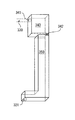
図13及び図14に示すように、下部インク収容室390には前室形成壁523が形成され、前室形成壁523は下流側インクエンドセンサ連絡通路410のインク入り口部427に連通するインク排出口(液体収容部出口)311を覆っている。前室形成壁523には切欠開口529が形成され、下部インク収容室390のインクは、切欠開口529を通過して前室531内へ流入する。前室531に流入したインクは、インク排出口311から迷路流路526を通ってインク入り口部427へ抜け、下流側インクエンドセンサ連絡通路410を流れてインク流入開口423(液体流入開口)へ入り、液体残量センサ31を通過する。
As shown in FIGS. 13 and 14, a front
即ち、下部インク収容室390には、インク収容室の一部分を構成する前室531が設けられている。前室531内には、図15に示すように、第1の内壁面である底面535と、この底面535に交わる第2の内壁面である側壁面537とによって隅部539が形成される。そして、インク排出口311は、この側壁面537に近接して底面535に穿設されている。
That is, the lower
尚、この側壁面537に近接して底面535に穿設されるインク排出口311の具体的な穿設位置としては、図15に示すように、下部インク収容室390に収容されるインクIによって隅部539に形成されるメニスカス543より内側の領域が挙げられる。
即ち、下部インク収容室390では、インク量が少なくなると、底面535と側壁面537とに挟まれて形成される隅部539に、毛管現象による表面張力により残ったインクIが集まってメニスカス543が形成される。
Incidentally, as a specific drilling position of the
That is, in the lower
そして、この隅部539に形成されるメニスカス543より内側の領域における底面535にインク排出口311が配設されることで、残ったインクIがインク排出口311を介して下流側インクエンドセンサ連絡通路410へ排出され易くなる。また、下部インク収容室390のインクIが徐々に減少した場合、残ったインクIのメニスカス543の一部がインク排出口311を液封するように集まり易く、インクIが下部インク収容室390に存在する状態で、先に空気がインク排出口311から排出され難くなる。
The
このように、インク排出口311が、下部インク収容室390に収容されるインクIの物性(特に粘度等)により異なった形状・大きさで形成されるメニスカス543の内側に配置されることで、毛管現象による表面張力によって隅部539に集まるインクIが確実に抜き取り可能となり、インクIに応じた最適な排出効果が得られる。
As described above, the
また、本実施形態に係るインクカートリッジ1は、第1の内壁面がインクジェット式プリンタのカートリッジ装着部に容器本体10を装着した姿勢の下部インク収容室390の底面535であり、残インクの最も残り易い底面535にインク排出口311が穿設されている。
そこで、最後の残インクまでインク排出口311へ誘導でき、残インクの抜き取り性を向上させることができる。また、残インクの掃け性も向上する。
In the
Therefore, it is possible to guide to the
ここで、インク排出口311は、下部インク収容室390に収容されるインクIによってメニスカスの形成される程度に小さい丸穴であることが好ましい。具体的には、一般的な物性値を有するインクIが用いられた場合、その直径が0.8mm程度となる。このような丸穴とすることで、インク排出口311に表面張力によって強いメニスカスが形成され、下部インク収容室390内の残液が少なくなり、かつ手によって振られ、下部インク収容室390内の気液が攪拌された場合であっても、インク排出口311に形成されたメニスカスが障壁となり、インク排出口311からの気泡の流出を防止できる。
Here, the
更に、上記実施形態に係るインクカートリッジ1の前室531内には、図14及び図16に示すように、第1の内壁面である底面535に交わって互いに対向する一対の側壁面(一対の内壁面)545,547が設けられている。そして、インク排出口311は、これら一対の側壁面545,547の間における底面535に穿設されている。
具体的には、一般的な物性値を有するインクIが用いられた場合、一対の側壁面545,547の間隔が2mm程度となる。このように、一対の側壁面545,547が互いに対向して近接配置されることで、一対の側壁面545,547の間にメニスカス543が生じ易くなり、下部インク収容室390内の残ったインクIのメニスカス543の一部が毛管現象によってインク排出口311を液封するよう誘導され易くなる。つまり、インクIの抜き取り効果を一層高めることができる。
Further, in the
Specifically, when ink I having general physical property values is used, the distance between the pair of side wall surfaces 545 and 547 is about 2 mm. As described above, the pair of side wall surfaces 545 and 547 are arranged close to each other so that a
さらに、本実施形態に係るインクカートリッジ1は、図16に示すように、インク排出口311の流入液上流側に、液流入間隙Sを隔てて対向壁551が配設されている。
この対向壁551は、前室形成壁523の一部分とすることができる。つまり、前室形成壁523は、図13に示したように、切欠開口529がインク排出口311とずれて配設されている。
Further, in the
The facing
このような構成とすることで、使用中の容器本体10がインクジェット式プリンタから脱着され、手によって振られ、下部インク収容室390内の気液が攪拌された場合であっても、攪拌により流動する気液の殆どが対向壁551に衝突し、衝突によりインク排出口311に直接的に加わる衝撃が低減され、気泡の流出を効果的に防止できるようになっている。
したがって、このインクカートリッジ1によれば、下部インク収容室390を下流側インクエンドセンサ連絡通路410に連通させるインク排出口311が、下部インク収容室390の底面535に交わる側壁面537及び内壁面545,547に囲まれた底面535に穿設されているので、下部インク収容室390内でインクIが少なくなると、これら側壁面537及び内壁面545,547に囲まれたインク排出口311の近傍に、毛管現象による表面張力によってインクIが集まり易くなる。
With such a configuration, even when the
Therefore, according to the
そこで、下部インク収容室390に残ったインクIは、インク排出口311を介して下流側インクエンドセンサ連絡通路410へ排出され易くなる。また、下部インク収容室390のインクが徐々に減少した場合、残ったインクIによるメニスカス543の一部がインク排出口311を液封するように集まり易いので、インクIが下部インク収容室390に存在する状態で先に空気がインク排出口311から排出され難くなる。
したがって、インクカートリッジ1内にインクIが残り難くなり、かつ下部インク収容室390内の空気が下流に入り込み難くなる。この結果、インクカートリッジ1のインク掃け性、耐気泡流出性を向上させることができる。
Therefore, the ink I remaining in the lower
Therefore, it is difficult for the ink I to remain in the
更に、以上のような構成を有することで、下流側インクエンドセンサ連絡通路410への空気の流入を検知することで下部インク収容室390のインクが消尽されたことを検出する液体残量センサ31が設けられたインクカートリッジ1の場合、インク掃けの悪さから、一旦インク終了が検知された下部インク収容室390内に多量の残インクが生じるのを防止したり、使用中の気泡による誤検出を防止したりして液体残量センサ31の検出精度を向上させることができる。
Further, by having the above-described configuration, the remaining
なお、上記実施形態では、底面535と側壁面537とが垂直に交わる場合を例示したが、図17に示すように、底面535と側壁面537aとが鋭角に交わり、鋭角の隅部539aを形成するように構成してもよい。
この場合、鋭角の隅部539aを形成することにより、より強い表面張力によって、残ったインクIを底面535と側壁面537aとの隅部539aに集めてメニスカス543を形成することが可能となる。
In the above embodiment, the case where the
In this case, the
また、上記実施形態のインクカートリッジ1では、底面535を第1の内壁面としてインク排出口311を穿設したが、例えば図18に示すように、側壁面549を第1の内壁面としてインク排出口311を穿設し、側壁面549に交わる第2の内壁面を底面535とすることもできる。
In the
この場合、インク排出口311を底面535に設けた上記実施形態の構成と同様の良好なインク抜き効果、気泡流出抑止効果が得られる。これに加えて、下部インク収容室390の内部空間が上下に延在する扁平空間である場合(すなわち、図2に示したように、高さ方向に広く、幅方向に狭い場合)、第1の内壁面を底面535とすることで、当該扁平空間を形成する側壁面549にインク排出口311が設けられることとなる。
即ち、手による容器本体10の攪拌時に、攪拌による衝撃の加わりにくい幅方向の側壁面549にインク排出口311が開口し、気泡を一層流出し難くできる。
In this case, the same good ink removal effect and bubble outflow suppression effect as those of the above embodiment in which the
That is, when the container
次に、大気開放孔100から上部インク収容室370に至るまでの大気連通路150、図8〜図12を参照しながら説明する。
インクカートリッジ1内のインクIが消費されてインクカートリッジ1内部の圧力が低下すると、貯留しているインクIの減少分だけ大気開放孔100から大気(空気)が上部インク収容室370に流入する。
Next, the
When the ink I in the
大気開放孔100の内部に設けられた小穴102は、カートリッジ本体10の背面側に形成された蛇道310の一端に連通している。蛇道310は、大気開放孔100から上部インク収容室370までの距離を長くしインク中の水分の蒸発を抑制するように細長く形成された蛇行路である。蛇道310の他端は、気液分離フィルタ70に接続されている。
A
気液分離フィルタ70を構成する気液分離室70aの底面には、貫通孔322が形成されており、貫通孔322を介してカートリッジ本体10の正面側に形成された空間320に連通している。
気液分離フィルタ70においては、貫通孔322と蛇道310の他端との間に気液分離膜71が配置される。気液分離膜71は撥水性および撥油性の高い繊維材料をメッシュ状に編みこんだもので形成される。
A through-
In the gas-
空間320は、カートリッジ本体10の正面側からみて上部インク室370の右上方に形成されている。空間320には、貫通孔322の上部に貫通孔321が開口している。空間320は、この貫通孔321を介して背面側に形成された上部連結流路330に連通している。
The
上部連結流路330は、インクカートリッジ1の最も上面側、すなわちインクカートリッジ1が取り付けられた状態における重力方向で最も上となる部分を通過するように、背面側から見て貫通孔321から長辺に沿って右方向に延びる流路部分333と、短辺近傍の折り返し部335で折り返して流路部分333よりもインクカートリッジ1の上面側を通って貫通孔321の近傍に形成された貫通孔341まで延びる流路部分337とを有している。なお、貫通孔341は、正面側に形成されたインクトラップ室340に連通している。
The upper connecting
ここで、背面側からこの上部連結流路330を見ると、折り返し部335から貫通孔341まで延びる流路部分337には、貫通孔341が形成された位置336と、位置336よりカートリッジ厚さ方向位置が深く掘り下げられた凹部332が設けられており、この凹部332を区切るようにリブ331が複数形成されている。また、貫通孔321から折り返し部335まで延びる流路部分333は、折り返し部335から貫通孔341まで延びる流路部分337よりも深さが浅く形成されている。
Here, when the upper connecting
本実施形態では、上部連結流路330を重力方向で最も上となる部分に形成しているので、基本的にはインクIが上部連結流路330を超えて大気開放孔100側に移動しないように構成されている。また、上部連結流路330は、毛細管現象等によりインクIの逆流が発生しない程度に幅広の太さを有するとともに、流路部分337には凹部332が形成されているので逆流してきたインクIを捕捉しやすく構成されている。
In the present embodiment, since the
インクトラップ室340は、正面側から見てカートリッジ本体10における右上方の隅の位置に形成された直方体形状の空間である。貫通孔341は、図12に示すように、正面側から見てインクトラップ室340の左上方奥側隅部近傍に開口している。また、インクトラップ室340の右下方手前側隅部には、仕切となるリブ10aの一部が切り欠かれた切り欠き部342が形成されており、この切り欠き部342を介して連絡バッファ室350に連通している。
The
ここで、インクトラップ室340および連絡バッファ室350は、大気連通路150の途中の容積を拡張した形態の空気室であり、何らかの理由により上部インク収容室370からインクIが逆流した場合でも、このインクトラップ室340および連絡バッファ室350にインクIを留め、これ以上大気開放孔100側へなるべく流れ込まないように構成されたものである。具体的なインクトラップ室340および連絡バッファ室350の役割については後述する。
Here, the
連絡バッファ室350は、インクトラップ室340の下方に形成された空間である。連結バッファ室350の底面352には、インク注入時に空気抜きを行うための減圧孔110が設けられている。また、底面352近傍であってインクジェット式記録装置への装着時最も重力方向下方の部位には、厚さ方向側に貫通孔351が開口しており、この貫通孔351を介して背面側に形成された連絡流路360に連通している。
The
連絡流路360は、背面側から見て中央上方側に延びており、上部インク収容室370の底壁近傍に開口した大気連通路150の下流端である貫通孔372を介して上部インク収容室370と連通している。すなわち、大気開放孔100から連絡流路360までが本実施形態の大気連通路150を構成している。連絡流路360は、メニスカスを形成し、インクIの逆流が発生しない程度の細さに形成されている。
The
本実施形態のインクカートリッジ1の場合、図8にも示したように、カートリッジ本体10の正面側には、前述のインク収容室(上部インク収容室370、下部インク収容室390、バッファ室430)や、空気室(インクトラップ室340、連絡バッファ室350)や、インク誘導路(上流側インクエンドセンサ連絡流路400、下流側インクエンドセンサ連絡流路410)の他に、インクIが充填されない未充填室501が画成されている。
In the case of the
未充填室501は、カートリッジ本体10の正面側で、ハッチングを施した左側面寄りの領域で、上部インク収容室370と下部インク収容室390とに挟まれるように区画形成されている。
そして、この未充填室501は、その内部領域の左上隅に、背面側に貫通した大気開放孔502が設けられ、該大気開放孔502により外気に連通している。
The
The
この未充填室501は、インクカートリッジ1を減圧パック包装した時に、脱気用負圧を蓄圧した脱気室となる。そこで、使用前にはカートリッジ本体10内部の気圧が未充填室501と減圧パックの負圧吸引力により規定値以下に保たれ、溶存空気の少ないインクIを供給することができる。
The
次に、以上に説明したインクカートリッジ1内のインクIが消尽された場合に、その使用済みのインクカートリッジ1にインクIを注入する方法の一実施形態を、図19に基づいて説明する。
Next, an embodiment of a method for injecting ink I into the used
まず、本実施形態の注入方法で使用するインク再注入装置の構成について説明する。
インク再注入装置600は、図19に示すように、インクカートリッジ1に穿孔加工により開けた注入口601に接続されるインク注入手段610と、カートリッジ本体10のインク供給部50に接続される真空吸引手段620とから構成されている。
First, the configuration of the ink re-injection apparatus used in the injection method of this embodiment will be described.
As shown in FIG. 19, the
インク注入手段610は、充填するインクIを貯留したインクタンク611と、このインクタンク611内のインクIを前記注入口601に接続された流路612に圧送するポンプ613と、このポンプ613と注入口601との間で流路612を開閉するバルブ614とを備えている。
The ink injection means 610 includes an
真空吸引手段620は、真空吸引に必要な負圧を発生する真空ポンプ621と、この真空ポンプ621の発生する負圧をインク供給部50に作用させる連絡流路622と、連絡流路622の途中に装備されて真空吸引によりカートリッジ本体10側から連絡流路622に流入してきたインクIを捕捉・回収して、インクミスト等から真空ポンプ621を保護するインクトラップ623と、このインクトラップ623とインク供給部50との間で連絡流路622を開閉するバルブ624とを備えている。
The vacuum suction means 620 includes a
本実施形態では、インクカートリッジ1の構造や機能を配慮し、上部インク収容室370に連通する注入口601を大気連通路150に形成する位置が、大気連通路150の一部を構成している連絡流路360の下流端に位置する貫通孔372と対向する位置付近とされる。
In the present embodiment, in consideration of the structure and function of the
そして、貫通孔372と対向する注入口601は、貫通孔372に一致するように、カートリッジ本体10の背面側を覆っている外表面フィルム60に孔を開けることで形成する。なお、該注入口601に挿入される流路612の先端部は、例えば、貫通孔372に押し当てると、貫通孔372の周囲の容器壁面に気密に密着して、流路612と貫通孔372とを気密な接続状態とするシールリング等が設けられている。
The
なお、上部インク収容室370に連通する注入口601は、上部インク収容室370より上流に位置する大気連通路150に形成すれば良く、注入口601の形成位置は上記実施形態に限らない。
例えば、大気連通路150の一部を構成している連絡流路360に一致するように、外表面フィルム60に孔を開けたり、外表面フィルム60を剥がしたりすることで注入口601を形成することができる。また、気液分離フィルタ70を構成する気液分離室70aに開口する貫通孔322に一致するように、外表面フィルム60及び気液分離膜71を剥がして注入口601を形成することもできる。
The
For example, the
更に、インクカートリッジ1から蓋部材20を取り外して、カートリッジ本体10の正面側を覆うフィルム80を露出させ、大気連通路150の一部を構成している連絡流路360の上端に位置する貫通孔351に一致するように、フィルム8に孔を開けることで形成することもできる。
Further, the
本実施形態では、先ず、上部インク収容室370に連通する注入口601を大気連通路150に形成する注入口形成工程と、インク供給部50から内部に残留するインク及び残留気体を真空吸引手段620により吸引除去する真空吸引工程と、注入口601からインク注入手段610により所定量のインクを注入する液体注入工程と、液体注入工程の終了後に注入口601を封止する封止工程と、を順に実施することで、使用済みのインクカートリッジ1を、再び使用可能なインクカートリッジ(液体収容容器)として復活させる。
封止工程は、具体的には注入口601を封止フィルムの接着,溶着、栓等で気密に塞ぐ処理工程である。
In the present embodiment, first, an injection port forming step of forming an
Specifically, the sealing step is a processing step of sealing the
以上に説明した本実施形態のインクカートリッジのインク注入方法では、インクIの注入のためにインクカートリッジ1に実施する加工は、上部インク収容室370に連通するように、インクIを注入するための注入口601を外表面フィルム60に開口させることと、インクIの注入後に、注入口601を封止する加工であり、いずれも簡単な加工となる。従って加工コストが安価で済み、また、手間もかからない。
In the ink injection method of the ink cartridge of the present embodiment described above, the processing performed on the
そして、本実施形態では、インク供給部50から内部に残留するインク及び残留気体を吸引除去する真空吸引工程を備えているため、注入口601から所定量のインクIを注入する液体注入工程は、カートリッジ本体10の各インク誘導路380,420,440や各インク収容室を減圧環境に管理して、注入したインクIを、インク収容室370,390,430だけでなく、インク供給部50に至るすべてのインク誘導路の隅々まで、効率よく充填できる。
In the present embodiment, since a vacuum suction process for sucking and removing the ink and residual gas remaining from the
また、インクIの注入時に混入する気泡も、真空吸引によりインク供給部50から外部に排除したり、あるいは真空吸引により形成する容器内の減圧環境により、流入した気泡を液中に溶解・消滅させたりすることができる。
従って、インクIの注入時に混入する気泡が、インク収容室やインク誘導路に浮遊したり、あるいは流路壁面に付着して残存することがなく、例えば、液体残量センサの検出部付近に気泡が残存することにより液体残量センサが正常に作動しなくなるといった不都合も生じない。
Also, bubbles that are mixed during the injection of the ink I are removed from the
Therefore, bubbles that are mixed during the injection of the ink I do not float in the ink storage chamber or the ink guide path or do not remain attached to the wall surface of the flow path. Therefore, there is no inconvenience that the liquid remaining amount sensor does not operate normally due to the remaining of water.
即ち、上記構成によれば、使用済みのインクカートリッジ1にインクを注入する際に、カートリッジ本体10への加工が少なくて済み、しかも、そのインクカートリッジ1の諸機能を損なうことなくインクを注入することができ、使用済みのインクカートリッジ1を安価に利用することができる。
That is, according to the above configuration, when ink is injected into the used
そして、このようなインク注入方法により再生した再生インクカートリッジを提供すれば、インクカートリッジの容器としての製品寿命が延びるため、資源の節約、環境汚染の防止に貢献することができる。また、再生に要するコストが低く、安価に提供できるため、インクジェット式記録装置の運用コストの低下にも貢献する。 If a regenerated ink cartridge regenerated by such an ink injection method is provided, the product life as a container of the ink cartridge is extended, which can contribute to resource saving and prevention of environmental pollution. In addition, since the cost required for reproduction is low and can be provided at a low cost, it contributes to a reduction in the operating cost of the ink jet recording apparatus.
なお、上述した本実施形態のインクカートリッジのインク注入方法において、真空吸引工程と液体充填工程との間に、注入口601からカートリッジ本体10内に洗浄液を注入して、容器内部で凝固したインクの洗浄・除去を行うようにしても良い。また、真空吸引工程と液体充填工程とは、明確に処理順を設定する必要はない。例えば、真空吸引工程を実施しながら、並行して液体充填工程を実施することもできる。
In the ink injection method of the ink cartridge of the present embodiment described above, the cleaning liquid is injected into the cartridge
また、本実施形態のインク注入方法を実施する際に使用するインク再注入装置600は、具体的には入手が容易な器具を代用することもできる。
例えば、インク注入手段610の場合、注射器の用にシリンダとピストンで構成される注入器を代用したり、変形可能なペットボトルに補充インクを収容した補充ボトルを代用したりすることもできる。
In addition, the
For example, in the case of the ink injection means 610, an injector composed of a cylinder and a piston can be substituted for the syringe, or a refill bottle containing refill ink in a deformable PET bottle can be substituted.
なお、本発明に係る液体収容容器における容器本体、液体収容部、液体供給部、液体誘導路、大気連通路、液体検出部及び堰部等の構成は、上記各実施形態の構成に限定されるものではなく、本発明の趣旨に基づいて種々の形態を採りうることは云うまでもない。 The configurations of the container main body, the liquid storage unit, the liquid supply unit, the liquid guide path, the air communication path, the liquid detection unit, the weir unit, and the like in the liquid storage container according to the present invention are limited to the configurations of the above embodiments. It goes without saying that various forms can be adopted based on the gist of the present invention.
また、本発明の液体収容容器の用途は、上述したインクジェット記録装置のインクカートリッジに限らない。微小量の液滴を吐出させる液体噴射ヘッド等を備える各種の液体消費装置に流用可能である。
液体消費装置の具体例としては、例えば液晶ディスプレー等のカラーフィルタ製造に用いられる色材噴射ヘッドを備えた装置、有機ELディスプレー、面発光ディスプレー(FED)等の電極形成に用いられる電極材(導電ペースト)噴射ヘッドを備えた装置、バイオチップ製造に用いられる生体有機物噴射ヘッドを備えた装置、精密ピペットとしての試料噴射ヘッドを備えた装置、捺染装置やマイクロデスペンサ等が挙げられる。
The use of the liquid container of the present invention is not limited to the ink cartridge of the above-described ink jet recording apparatus. The present invention can be used for various liquid consuming devices including a liquid ejecting head that discharges a minute amount of liquid droplets.
Specific examples of the liquid consuming device include, for example, an electrode material (conductive) used for forming an electrode such as a device having a color material ejecting head used for manufacturing a color filter such as a liquid crystal display, an organic EL display, and a surface emitting display (FED). Examples thereof include an apparatus having a paste) ejection head, an apparatus having a bio-organic matter ejection head used for biochip manufacturing, an apparatus having a sample ejection head as a precision pipette, a textile printing apparatus, and a micro dispenser.
1…インクカートリッジ(液体収容容器)、10…カートリッジ本体(容器本体)、20…蓋部材、30…インクエンドセンサ、31…液体残量センサ(液体検出部)、40…差圧弁、50…インク供給部(液体供給部)、70…気液分離フィルタ、80…フィルム、100…大気開放孔、150…大気連通路、200…キャリッジ、330…上部連結流路、340…インクトラップ室(空気室)、350…連結バッファ室(空気室)、370…上部インク収容室(液体収容室)、371,311,432…インク排出口(液体排出口)、374,394,434…窪み、375,395,435…液体収容室の底壁、380…インク誘導路(液体誘導路)、390…下部インク収容室(液体収容室)、391,431…インク流入口(液体流入口)、400…上流側インクエンドセンサ連絡流路(液体誘導路)、410…下流側インクエンドセンサ連絡流路(液体誘導路)、420…インク誘導路(液体誘導路)、423…インク流入開口(液体流入開口)、423a…内周上部、427…インク入り口部(入り口部)、430…バッファ室(液体収容室)、501…未充填室(脱気室)、535…底面(第1の内壁面)、537…側壁面(第2の内壁面)、539…隅部、543…メニスカス、545…側壁面(一対の内壁面)、547…側壁面(一対の内壁面)、S…液流入間隙、551…対向壁、B…気泡、I…インク(液体)、
DESCRIPTION OF
Claims (2)
(a)液体収容部と、前記液体消費装置に接続される液体供給部と、前記液体収容部に
貯留された液体を前記液体供給部に誘導するための液体誘導路と、前記液体収容部内の液
体の消費に伴って外部から大気を前記液体収容部内に導入するための、一部がフィルムで形成された大気連通路と、を備えると共に、前記液体収容部に、第1の内壁面と、該第1の内壁面に交わり、前記第1の内壁面から前記液体誘導路側とは反対側である前記液体収容部側に延びる第2の内壁面と、該第2の内壁面に近接した前記第1の内壁面に穿設されて前記液体収容部を前記液体誘導路に連通させる液体収容部出口と、を備える容器を用意する工程と、
(b)前記液体収容部に連通する注入口を前記大気連通路に形成する工程と、
(c)前記注入口から所定量の液体を注入する工程と、
(d)前記液体を注入する工程の終了後に前記注入口を封止する工程と、
を含み、
前記工程(b)において、前記大気連通路を形成するフィルムに孔を開けて前記注入口を形成することを特徴とする液体収容容器の製造方法。 A method for producing a liquid container detachable from a liquid consumption device,
(A) a liquid storage unit, a liquid supply unit connected to the liquid consumption device, a liquid guide path for guiding the liquid stored in the liquid storage unit to the liquid supply unit, and the liquid storage unit A part of the air communication passage formed of a film for introducing the air into the liquid container from the outside as the liquid is consumed, and the liquid container having a first inner wall surface; A second inner wall surface that intersects the first inner wall surface and extends from the first inner wall surface to the liquid container side opposite to the liquid guiding path side; and the second inner wall surface that is close to the second inner wall surface Preparing a container comprising: a liquid storage unit outlet formed in the first inner wall surface and communicating the liquid storage unit with the liquid guide path;
(B) forming an inlet port communicating with the liquid container in the atmosphere communication path;
(C) injecting a predetermined amount of liquid from the injection port;
(D) sealing the inlet after completion of the step of injecting the liquid;
Including
In the step (b), a method for producing a liquid container , comprising forming a hole in a film forming the atmosphere communication path to form the inlet .
Priority Applications (53)
| Application Number | Priority Date | Filing Date | Title |
|---|---|---|---|
| JP2006220755A JP4992338B2 (en) | 2006-08-11 | 2006-08-11 | Method for manufacturing liquid container |
| KR1020070080236A KR20080014664A (en) | 2006-08-11 | 2007-08-09 | Liquid injecting method and liquid container |
| KR1020070080260A KR100936840B1 (en) | 2006-08-11 | 2007-08-09 | Liquid injecting method and liquid container |
| US11/836,879 US7942510B2 (en) | 2006-08-11 | 2007-08-10 | Liquid injecting method and liquid container |
| ES07015771T ES2354992T3 (en) | 2006-08-11 | 2007-08-10 | METHOD OF INJECTION OF LIQUID AND DEPOSIT OF LIQUID. |
| EP07792420A EP2050570B1 (en) | 2006-08-11 | 2007-08-10 | Liquid filling method and liquid receiving container |
| TW096129713A TWI328525B (en) | 2006-08-11 | 2007-08-10 | Liquid injecting method and liquid container |
| PL07792420T PL2050570T3 (en) | 2006-08-11 | 2007-08-10 | Liquid filling method and liquid receiving container |
| CN200780029902.6A CN101500810B (en) | 2006-08-11 | 2007-08-10 | A method of injecting liquid and liquid container |
| ARP070103568A AR062342A1 (en) | 2006-08-11 | 2007-08-10 | LIQUID INJECTION METHOD AND LIQUID CONTAINER |
| PCT/JP2007/065777 WO2008018602A1 (en) | 2006-08-11 | 2007-08-10 | Liquid filling method and liquid receiving container |
| EP07015771A EP1886823B1 (en) | 2006-08-11 | 2007-08-10 | Liquid injecting method and liquid container |
| TW096129772A TWI328524B (en) | 2006-08-11 | 2007-08-10 | Liquid injecting method and liquid container |
| GB0715668A GB2440837B (en) | 2006-08-11 | 2007-08-10 | Liquid injecting method and liquid container |
| TW096129706A TWI327965B (en) | 2006-08-11 | 2007-08-10 | Liquid injecting method and liquid container |
| RU2009108648/05A RU2407646C2 (en) | 2006-08-11 | 2007-08-10 | Method of producing container for fluids (versions) and container for fluids (versions) |
| EP07015769A EP1886821B1 (en) | 2006-08-11 | 2007-08-10 | Liquid injecting method and liquid container |
| DE102007037915A DE102007037915A1 (en) | 2006-08-11 | 2007-08-10 | Liquid injection method and liquid container |
| AT07015769T ATE491578T1 (en) | 2006-08-11 | 2007-08-10 | LIQUID INJECTION PROCESS AND LIQUID TANK |
| GB0715663A GB2440834B (en) | 2006-08-11 | 2007-08-10 | Liquid injecting method and liquid container |
| FR0757042A FR2915707A1 (en) | 2006-08-11 | 2007-08-10 | PROCESS FOR INJECTING A LIQUID IN A LIQUID CONTAINER |
| KR1020097002749A KR101024158B1 (en) | 2006-08-11 | 2007-08-10 | Liquid filling method and liquid receiving container |
| KR1020070080562A KR20080014688A (en) | 2006-08-11 | 2007-08-10 | Liquid injecting method and liquid container |
| DE102007037912A DE102007037912A1 (en) | 2006-08-11 | 2007-08-10 | Liquid injection method and liquid container |
| ES07792420T ES2377212T3 (en) | 2006-08-11 | 2007-08-10 | Liquid filling method and liquid receiving tank |
| EP07015767A EP1886820A2 (en) | 2006-08-11 | 2007-08-10 | Liquid injecting method and liquid container |
| GB0814989A GB2451194B (en) | 2006-08-11 | 2007-08-10 | Liquid injecting method and liquid container |
| AT07792420T ATE540817T1 (en) | 2006-08-11 | 2007-08-10 | LIQUID FILLING METHOD AND LIQUID RECEIVING CONTAINER |
| CL200702335A CL2007002335A1 (en) | 2006-08-11 | 2007-08-10 | A METHOD FOR INJECTING A LIQUID IN A REMOVABLE MOUNTED LIQUID CONTAINER IN A LIQUID CONSUMER DEVICE THAT HAS LIQUID CONTAINING CAMERAS, WHERE AN INJECTION HOLE IS FORMED, AN AMOUNT AND LIQUID OF LIQUID IS INJECTED |
| DE602007010698T DE602007010698D1 (en) | 2006-08-11 | 2007-08-10 | Liquid injection method and liquid container |
| TW096129709A TW200824919A (en) | 2006-08-11 | 2007-08-10 | Liquid injecting method and liquid container |
| AU2007282345A AU2007282345B2 (en) | 2006-08-11 | 2007-08-10 | Liquid filling method and liquid receiving container |
| CA002660430A CA2660430A1 (en) | 2006-08-11 | 2007-08-10 | Liquid injecting method and liquid container |
| US11/836,820 US20080036805A1 (en) | 2006-08-11 | 2007-08-10 | Liquid injecting method and liquid container |
| AT07015771T ATE489229T1 (en) | 2006-08-11 | 2007-08-10 | LIQUID INJECTION PROCESS AND LIQUID TANK |
| TW096129710A TW200831301A (en) | 2006-08-11 | 2007-08-10 | Liquid injecting method and liquid container |
| EP11162208A EP2353873A1 (en) | 2006-08-11 | 2007-08-10 | Liquid injecting method and liquid container |
| US11/836,826 US20080036806A1 (en) | 2006-08-11 | 2007-08-10 | Liquid injecting method and liquid container |
| ES07015769T ES2355758T3 (en) | 2006-08-11 | 2007-08-10 | METHOD OF INJECTION OF LIQUID AND LIQUID DEPOSIT. |
| EP07015770A EP1886822A2 (en) | 2006-08-11 | 2007-08-10 | Liquid injecting method and liquid container |
| MYPI20090528A MY149588A (en) | 2006-08-11 | 2007-08-10 | Liquid injecting method and liquid container |
| BRPI0716484-0A2A BRPI0716484A2 (en) | 2006-08-11 | 2007-08-10 | METHOD FOR LIQUID INJECTION AND LIQUID CONTAINER |
| KR1020070080560A KR100938315B1 (en) | 2006-08-11 | 2007-08-10 | Liquid injecting method and liquid container |
| DE602007011163T DE602007011163D1 (en) | 2006-08-11 | 2007-08-10 | Liquid injection method and liquid container |
| CNA2007101357092A CN101121330A (en) | 2006-08-11 | 2007-08-10 | A liquid container having a bubble trapping passage and detection unit |
| MX2009001581A MX2009001581A (en) | 2006-08-11 | 2007-08-10 | Liquid filling method and liquid receiving container. |
| US11/836,857 US8177341B2 (en) | 2006-08-11 | 2007-08-10 | Liquid injecting method and liquid container |
| US11/837,782 US8235513B2 (en) | 2006-08-11 | 2007-08-13 | Liquid injecting method and liquid container |
| CNA2007101420128A CN101121338A (en) | 2006-08-11 | 2007-08-13 | Liquid inpouring method and a liquid container |
| CN 200710142010 CN100575094C (en) | 2006-08-11 | 2007-08-13 | Liquid inpouring method and liquid container |
| CN 200710142009 CN100584620C (en) | 2006-08-11 | 2007-08-13 | Liquid inpouring method and a liquid container |
| HK08108326.0A HK1117469A1 (en) | 2006-08-11 | 2008-07-28 | Liquid injecting method and liquid container |
| ZA200900963A ZA200900963B (en) | 2006-08-11 | 2009-02-10 | Liquid filling method and liquid receiving container |
Applications Claiming Priority (1)
| Application Number | Priority Date | Filing Date | Title |
|---|---|---|---|
| JP2006220755A JP4992338B2 (en) | 2006-08-11 | 2006-08-11 | Method for manufacturing liquid container |
Publications (3)
| Publication Number | Publication Date |
|---|---|
| JP2008044190A JP2008044190A (en) | 2008-02-28 |
| JP2008044190A5 JP2008044190A5 (en) | 2009-09-17 |
| JP4992338B2 true JP4992338B2 (en) | 2012-08-08 |
Family
ID=39083914
Family Applications (1)
| Application Number | Title | Priority Date | Filing Date |
|---|---|---|---|
| JP2006220755A Active JP4992338B2 (en) | 2006-08-11 | 2006-08-11 | Method for manufacturing liquid container |
Country Status (4)
| Country | Link |
|---|---|
| JP (1) | JP4992338B2 (en) |
| CN (5) | CN101121330A (en) |
| ES (2) | ES2354992T3 (en) |
| ZA (1) | ZA200900963B (en) |
Families Citing this family (22)
| Publication number | Priority date | Publication date | Assignee | Title |
|---|---|---|---|---|
| DE102008009626A1 (en) * | 2008-02-18 | 2009-08-27 | Advalytix Ag | Method for checking the state of a pipette, pipetting method, pipetting device and suction tube for a pipetting device |
| JP5390119B2 (en) * | 2008-05-01 | 2014-01-15 | エステー産業株式会社 | Refilling liquid ink in used ink cartridges |
| JP5163314B2 (en) | 2008-06-27 | 2013-03-13 | セイコーエプソン株式会社 | Method for injecting liquid into liquid container, method for manufacturing liquid container, liquid container |
| US8366251B2 (en) | 2008-06-27 | 2013-02-05 | Seiko Epson Corporation | Liquid container, method of filling liquid into liquid container, and remanufacturing method of liquid container |
| JP5163313B2 (en) | 2008-06-27 | 2013-03-13 | セイコーエプソン株式会社 | Method for manufacturing liquid container, liquid container |
| JP5272540B2 (en) | 2008-06-27 | 2013-08-28 | セイコーエプソン株式会社 | Liquid container manufacturing method and liquid container |
| JP2010023247A (en) | 2008-07-15 | 2010-02-04 | Seiko Epson Corp | Liquid supplying system and manufacturing method therefor |
| JP5919737B2 (en) * | 2010-12-08 | 2016-05-18 | セイコーエプソン株式会社 | Liquid detection system, liquid container |
| CN102909958B (en) * | 2011-08-04 | 2014-10-22 | 珠海纳思达企业管理有限公司 | Method for injecting ink into ink box |
| CN103358704A (en) * | 2012-03-30 | 2013-10-23 | 珠海纳思达电子科技有限公司 | Ink cartridge and method for injecting ink therein |
| US8894184B2 (en) * | 2012-05-23 | 2014-11-25 | Seiko Epson Corporation | Cover and liquid container |
| CN103419500B (en) * | 2012-05-23 | 2015-10-21 | 精工爱普生株式会社 | Box and seal member |
| US10647123B2 (en) * | 2012-07-23 | 2020-05-12 | Seiko Epson Corporation | Refilled cartridge and method for manufacturing refilled cartridge |
| RU2018105185A (en) * | 2012-08-10 | 2019-02-25 | Сейко Эпсон Корпорейшн | LIQUID CONTAINER, LIQUID CONSUMPTION DEVICE, LIQUID FEEDING SYSTEM AND LIQUID CONTAINER UNIT |
| JP6102150B2 (en) * | 2012-08-31 | 2017-03-29 | セイコーエプソン株式会社 | Method for manufacturing liquid container, liquid container |
| DE102012216881A1 (en) * | 2012-09-20 | 2014-03-20 | Kba-Metronic Gmbh | print Setup |
| CN203401814U (en) * | 2013-07-11 | 2014-01-22 | 珠海纳思达企业管理有限公司 | Regenerating ink cartridge |
| RU2729478C2 (en) * | 2015-12-14 | 2020-08-07 | Сарая Ко., Лтд. | Liquid supply system and method of its actuation |
| JP6433473B2 (en) | 2016-11-04 | 2018-12-05 | シスメックス株式会社 | Liquid-enclosed cartridge, method for producing liquid-enclosed cartridge, and liquid feeding method |
| JP7056329B2 (en) * | 2018-04-03 | 2022-04-19 | セイコーエプソン株式会社 | Liquid sprayer |
| CN212862328U (en) | 2020-05-08 | 2021-04-02 | 珠海纳思达企业管理有限公司 | Consumable packaging assembly |
| CN115283835B (en) * | 2022-07-05 | 2023-10-20 | 深圳明锐理想科技有限公司 | Defect marking method and device for PCB |
Family Cites Families (3)
| Publication number | Priority date | Publication date | Assignee | Title |
|---|---|---|---|---|
| JP3513979B2 (en) * | 1994-09-16 | 2004-03-31 | セイコーエプソン株式会社 | Ink cartridge for inkjet printer |
| CA2674665C (en) * | 2000-10-20 | 2013-01-22 | Seiko Epson Corporation | Ink cartridge for ink jet recording device |
| JP4715115B2 (en) * | 2004-06-23 | 2011-07-06 | ブラザー工業株式会社 | Ink filling method |
-
2006
- 2006-08-11 JP JP2006220755A patent/JP4992338B2/en active Active
-
2007
- 2007-08-10 CN CNA2007101357092A patent/CN101121330A/en active Pending
- 2007-08-10 ES ES07015771T patent/ES2354992T3/en active Active
- 2007-08-10 CN CN200780029902.6A patent/CN101500810B/en active Active
- 2007-08-10 ES ES07015769T patent/ES2355758T3/en active Active
- 2007-08-13 CN CN 200710142010 patent/CN100575094C/en active Active
- 2007-08-13 CN CN 200710142009 patent/CN100584620C/en active Active
- 2007-08-13 CN CNA2007101420128A patent/CN101121338A/en active Pending
-
2009
- 2009-02-10 ZA ZA200900963A patent/ZA200900963B/en unknown
Also Published As
| Publication number | Publication date |
|---|---|
| JP2008044190A (en) | 2008-02-28 |
| CN100584620C (en) | 2010-01-27 |
| CN100575094C (en) | 2009-12-30 |
| ES2354992T3 (en) | 2011-03-21 |
| CN101121338A (en) | 2008-02-13 |
| CN101121336A (en) | 2008-02-13 |
| ES2355758T3 (en) | 2011-03-30 |
| CN101500810B (en) | 2011-08-10 |
| ZA200900963B (en) | 2010-01-27 |
| CN101500810A (en) | 2009-08-05 |
| CN101121335A (en) | 2008-02-13 |
| CN101121330A (en) | 2008-02-13 |
Similar Documents
| Publication | Publication Date | Title |
|---|---|---|
| JP4992338B2 (en) | Method for manufacturing liquid container | |
| EP1886823B1 (en) | Liquid injecting method and liquid container | |
| JP4349474B2 (en) | Liquid container | |
| KR100936840B1 (en) | Liquid injecting method and liquid container | |
| JP4407678B2 (en) | Liquid injection method and liquid container | |
| JP5125277B2 (en) | Liquid injection method and liquid container manufacturing method | |
| AU2007282345B2 (en) | Liquid filling method and liquid receiving container | |
| JP4371175B2 (en) | Liquid container | |
| JP5282841B2 (en) | Liquid container | |
| JP4380671B2 (en) | Method for manufacturing liquid container | |
| US20080036805A1 (en) | Liquid injecting method and liquid container | |
| US20080036806A1 (en) | Liquid injecting method and liquid container | |
| JP5126187B2 (en) | Liquid container | |
| JP2008044192A (en) | Liquid injection method and liquid container | |
| JP2008044199A (en) | Liquid container | |
| JP2008044200A (en) | Liquid injection method and liquid container | |
| JP4780177B2 (en) | Liquid container |
Legal Events
| Date | Code | Title | Description |
|---|---|---|---|
| RD04 | Notification of resignation of power of attorney |
Free format text: JAPANESE INTERMEDIATE CODE: A7424 Effective date: 20080331 |
|
| RD04 | Notification of resignation of power of attorney |
Free format text: JAPANESE INTERMEDIATE CODE: A7424 Effective date: 20090716 |
|
| RD03 | Notification of appointment of power of attorney |
Free format text: JAPANESE INTERMEDIATE CODE: A7423 Effective date: 20090722 |
|
| A521 | Written amendment |
Free format text: JAPANESE INTERMEDIATE CODE: A523 Effective date: 20090804 |
|
| A621 | Written request for application examination |
Free format text: JAPANESE INTERMEDIATE CODE: A621 Effective date: 20090804 |
|
| A131 | Notification of reasons for refusal |
Free format text: JAPANESE INTERMEDIATE CODE: A131 Effective date: 20110531 |
|
| A521 | Written amendment |
Free format text: JAPANESE INTERMEDIATE CODE: A523 Effective date: 20110727 |
|
| TRDD | Decision of grant or rejection written | ||
| A01 | Written decision to grant a patent or to grant a registration (utility model) |
Free format text: JAPANESE INTERMEDIATE CODE: A01 Effective date: 20120410 |
|
| A01 | Written decision to grant a patent or to grant a registration (utility model) |
Free format text: JAPANESE INTERMEDIATE CODE: A01 |
|
| A61 | First payment of annual fees (during grant procedure) |
Free format text: JAPANESE INTERMEDIATE CODE: A61 Effective date: 20120423 |
|
| FPAY | Renewal fee payment (event date is renewal date of database) |
Free format text: PAYMENT UNTIL: 20150518 Year of fee payment: 3 |
|
| R150 | Certificate of patent or registration of utility model |
Ref document number: 4992338 Country of ref document: JP Free format text: JAPANESE INTERMEDIATE CODE: R150 Free format text: JAPANESE INTERMEDIATE CODE: R150 |
|
| S531 | Written request for registration of change of domicile |
Free format text: JAPANESE INTERMEDIATE CODE: R313531 |
|
| R350 | Written notification of registration of transfer |
Free format text: JAPANESE INTERMEDIATE CODE: R350 |