JP4780177B2 - Liquid container - Google Patents
Liquid container Download PDFInfo
- Publication number
- JP4780177B2 JP4780177B2 JP2008287089A JP2008287089A JP4780177B2 JP 4780177 B2 JP4780177 B2 JP 4780177B2 JP 2008287089 A JP2008287089 A JP 2008287089A JP 2008287089 A JP2008287089 A JP 2008287089A JP 4780177 B2 JP4780177 B2 JP 4780177B2
- Authority
- JP
- Japan
- Prior art keywords
- liquid
- ink
- storage chamber
- liquid storage
- chamber
- Prior art date
- Legal status (The legal status is an assumption and is not a legal conclusion. Google has not performed a legal analysis and makes no representation as to the accuracy of the status listed.)
- Active
Links
Images


Description
本発明は、液体消費装置に着脱可能に装着される容器本体内に貯留している液体を前記
液体消費装置に供給する大気開放タイプの液体収容容器に液体を注入する方法及びそれに
より製造した液体収容容器に関する。
The present invention relates to a method for injecting liquid into an air-opening type liquid storage container that supplies liquid stored in a container main body detachably attached to the liquid consuming apparatus to the liquid consuming apparatus, and liquid manufactured thereby Concerning the container.
上記液体収容容器及び液体消費装置の例として、例えば、インク液を貯留した大気開放
タイプのインクカートリッジと、該インクカートリッジが交換可能に装着されるインクジ
ェット式記録装置を挙げることができる。
As an example of the liquid container and the liquid consuming device, for example, an air release type ink cartridge storing ink liquid and an ink jet type recording device on which the ink cartridge is replaceably mounted can be cited.
上記インクカートリッジは、通常、インクジェット式記録装置のカートリッジ装着部に
着脱可能に装着される容器本体内に、インクIが充填されるインク収容室と、前記インク
収容室に貯留されている液体をインクジェット式記録装置に供給するためのインク供給孔
と、前記インク収容室とインク供給孔とを連通するインク誘導路と、前記インク収容室内
のインクIの消費に伴って外部から大気を前記インク収容室内に導入する大気連通路とを
備えた構成とされていて、記録装置のカートリッジ装着部に装着された際に前記カートリ
ッジ装着部に装備されたインク供給針が前記インク供給孔に挿入接続されることにより、
貯留しているインクIがインクジェット式記録装置の記録ヘッドに供給可能になる。
The ink cartridge is usually an ink storage chamber filled with ink I in a container body that is detachably mounted on a cartridge mounting portion of an ink jet recording apparatus, and ink stored in the ink storage chamber. An ink supply hole for supplying to the ink jet recording apparatus, an ink guiding path communicating with the ink storage chamber and the ink supply hole, and air from the outside as the ink I is consumed in the ink storage chamber The ink supply needle mounted on the cartridge mounting portion is inserted and connected to the ink supply hole when mounted on the cartridge mounting portion of the recording apparatus. By
The stored ink I can be supplied to the recording head of the ink jet recording apparatus.
インクジェット式記録装置における記録ヘッドは、熱や振動を利用してインク滴の噴射
を制御するもので、インクカートリッジがインク切れになり、インクIが供給されない状
態でインク吐出動作を行う空打ちが発生すると、故障してしまう。そこで、インクジェッ
ト式記録装置では、記録ヘッドが空打ちをしないように、インクカートリッジにおけるイ
ンク液の残量を監視する必要が生じる。
The recording head in the ink jet recording device controls the ejection of ink droplets using heat and vibration, and the ink cartridge runs out of ink, causing the ink ejection to occur while ink I is not supplied. Then, it breaks down. Therefore, in the ink jet recording apparatus, it is necessary to monitor the remaining amount of ink in the ink cartridge so that the recording head does not run idle.
このような背景から、インクカートリッジに貯留されたインクを完全に最後まで使い切
ってしまって、記録装置の記録ヘッドに空打ちを招くことがないように、容器本体内に貯
留したインクIの残量が予め設定した閾値まで消費された時に、所定の電気信号を出力す
る液体残量センサを備えるインクカートリッジが開発されている(例えば、特許文献1)
。
Against this background, the remaining amount of ink I stored in the container body is used so that the ink stored in the ink cartridge is not completely used up and the recording head of the recording apparatus is not emptied. Has been developed that includes a liquid remaining amount sensor that outputs a predetermined electrical signal when the ink is consumed up to a preset threshold value (for example, Patent Document 1).
.
ところで、インクカートリッジは、多数の部品から構成される高精度な容器で、コスト
的には、内容物であるインクよりも、容器の方がコストがかかる。そのため、インクを消
尽した時に、そのまま廃棄することは、有用な資源の廃棄となり、経済的に大きな損失と
なってしまう。
そこで、使用済みのインクカートリッジにインクを注入して利用することが望まれてい
る。
By the way, the ink cartridge is a high-accuracy container composed of a large number of parts, and in terms of cost, the container costs more than the ink that is the contents. For this reason, when the ink is exhausted, discarding the ink as it is results in the disposal of useful resources and a large economic loss.
Therefore, it is desired to use ink by injecting it into a used ink cartridge.
ところが、従来のインクカートリッジは、その組み立て工程の途中に、インクIの充填
工程を組み込んでいて、インクカートリッジの組み立て完了後は、同様のインク充填方法
が利用できない場合が多い。
そこで、新品のインクカートリッジを組み立てる際のインク充填方法は使わずに、イン
クIの充填を実現する再生方法の開発が必要となる。
However, in the conventional ink cartridge, the ink I filling process is incorporated in the middle of the assembly process, and the same ink filling method cannot often be used after the ink cartridge is assembled.
Therefore, it is necessary to develop a regeneration method that realizes the filling of ink I without using the ink filling method when assembling a new ink cartridge.
しかし、近年のインクカートリッジは、インク収容室とインク供給孔とを連通するイン
ク誘導路に、インク供給孔へ供給するインク圧を調整すると共にインク供給孔側からの逆
流を防止する逆止弁としても機能する差圧弁が設けられていたり、あるいはインクIの残
量を検出する液体残量センサが備えられて、高性能化されている。更には、貯留している
インクIの品質を長期に渡って維持するために、インク収容室や大気連通路の構造も複雑
化している。
そのため、インクIの注入のために、不用意に容器本体を加工すると、インクを注入し
た際に、インク収容室以外の部分にインクIが漏れたり、インク充填時に混入する気泡Bの
ために当初の機能が損なわれて、再生不良を招く虞がある。
また、注入のために容器本体に施す加工が複雑で、加工コストの高額化のために、再生
コストが新規のインクカートリッジの製造コストを上回るようでは、再生の意義が薄れて
しまう。
However, recent ink cartridges use a check valve that adjusts the ink pressure supplied to the ink supply hole and prevents backflow from the ink supply hole side in the ink guide path that communicates the ink storage chamber and the ink supply hole. A high-performance differential pressure valve is provided, or a liquid remaining amount sensor for detecting the remaining amount of ink I is provided. Furthermore, in order to maintain the quality of the stored ink I over a long period of time, the structure of the ink storage chamber and the atmosphere communication path is also complicated.
Therefore, if the container body is carelessly processed for the injection of ink I, when the ink is injected, the ink I leaks to the part other than the ink storage chamber, or the air bubbles B are mixed at the time of ink filling. There is a risk that the function of the above will be impaired, leading to poor reproduction.
In addition, the processing applied to the container body for injection is complicated, and if the recycling cost exceeds the manufacturing cost of a new ink cartridge due to an increase in processing cost, the significance of the regeneration is reduced.
そこで、本発明は、使用済みの液体収容容器に液体を注入する際に、容器本体への加工
が少なくて済み、しかも、その液体収容容器の諸機能を損なうことなく液体を注入するこ
とができ、使用済みの液体収容容器を安価に利用することを目的とする。
Therefore, according to the present invention, when injecting a liquid into a used liquid storage container, processing into the container main body is reduced, and the liquid can be injected without impairing various functions of the liquid storage container. The purpose is to use a used liquid container at low cost.
(1)本発明の上記課題の解決は、液体消費装置に装着される容器本体内に、
液体を収容する液体収容室と、
前記液体消費装置に接続される液体供給孔と、
前記液体収容室に貯留されている液体を前記液体供給孔に誘導する液体誘導路と、
前記液体収容室内の液体の消費に伴って外部から大気を前記液体収容室内に導入する大
気連通路と、
前記液体誘導路の途中に設けられ、当該液体誘導路への気体の流入を検知することで前
記液体収容室の液体が消尽されたことを検出する液体残量センサと、が備えられると共に
、
前記大気連通路の途中には、他の連通路部分よりも細く形成され、前記液体収容室に収
容されている液体の一部をメニスカスにより保持可能な細い連通路部分が設けられ、
前記細い連通路部分に保持された液体により、前記液体収容室に収容されている液体を
大気と遮断可能な大気開放タイプの液体収容容器に液体を注入する方法であって、
前記細い連通路部分の上流端より上流で注入口を形成する工程と、
前記注入口から所定量の液体を注入する工程と、
前記液体充填工程の終了後に前記注入口を封止する工程と、を含む液体注入方法により
達成される。
(1) The solution of the above-described problem of the present invention is to provide a container body mounted on the liquid consuming apparatus,
A liquid storage chamber for storing a liquid;
A liquid supply hole connected to the liquid consumption device;
A liquid guide path for guiding the liquid stored in the liquid storage chamber to the liquid supply hole;
An atmosphere communication path for introducing the atmosphere into the liquid storage chamber from the outside as the liquid in the liquid storage chamber is consumed;
A liquid remaining amount sensor that is provided in the middle of the liquid guide path and detects that the liquid in the liquid storage chamber has been exhausted by detecting the inflow of gas into the liquid guide path; and
In the middle of the atmosphere communication path, a narrow communication path part that is formed thinner than the other communication path part and can hold a part of the liquid stored in the liquid storage chamber by a meniscus is provided,
A method of injecting a liquid into an open air type liquid storage container capable of shutting off the liquid stored in the liquid storage chamber from the atmosphere by the liquid held in the narrow communication path part,
Forming an inlet upstream from an upstream end of the narrow communication passage portion;
Injecting a predetermined amount of liquid from the injection port;
And a step of sealing the inlet after the liquid filling step is completed.
上記構成によれば、液体の注入のために容器本体に実施する加工は、液体を注入するた
めの注入口を開口させることと、液体の充填後に、前記注入口を封止する加工で、いずれ
も簡単な加工となる。使用済みの液体収容容器に液体を注入する際に、容器本体への加工
が少なくて済み、しかも、その液体収容容器の諸機能を損なうことなく液体を注入するこ
とができ、使用済みの液体収容容器を安価に利用することができる。
According to the above configuration, the processing performed on the container body for injecting the liquid may be performed by opening the injection port for injecting the liquid and sealing the injection port after filling the liquid. Even simple processing. When injecting a liquid into a used liquid storage container, the processing into the container body can be reduced, and the liquid can be injected without impairing the functions of the liquid storage container. The container can be used at low cost.
(2)本発明の上記課題の解決は、液体消費装置に装着される容器本体内に、
液体を収容する液体収容室と、
前記液体消費装置に接続される液体供給孔と、
前記液体収容室に貯留されている液体を前記液体供給孔に誘導する液体誘導路と、
前記液体収容室内の液体の消費に伴って外部から大気を前記液体収容室内に導入する大
気連通路と、
前記液体誘導路の途中に設けられ、当該液体誘導路への気体の流入を検知することで前
記液体収容室の液体が消尽されたことを検出する液体残量センサと、が備えられると共に
、
前記大気連通路の途中には、他の連通路部分よりも細く形成され、前記液体収容室に収
容されている液体の一部をメニスカスにより保持可能な細い連通路部分が設けられ、
前記細い連通路部分に保持された液体により、前記液体収容室に収容されている液体を
大気と遮断可能な大気開放タイプの液体収容容器に対し、
前記細い連通路部分の上流端より上流で注入口を形成し、前記注入口から所定量の液体
を注入し、前記液体充填工程の終了後に前記注入口を封止して成る液体収容容器により達
成される。
(2) The solution to the above-described problem of the present invention is to provide a container body mounted on the liquid consuming apparatus,
A liquid storage chamber for storing a liquid;
A liquid supply hole connected to the liquid consumption device;
A liquid guide path for guiding the liquid stored in the liquid storage chamber to the liquid supply hole;
An atmosphere communication path for introducing the atmosphere into the liquid storage chamber from the outside as the liquid in the liquid storage chamber is consumed;
A liquid remaining amount sensor that is provided in the middle of the liquid guide path and detects that the liquid in the liquid storage chamber has been exhausted by detecting the inflow of gas into the liquid guide path; and
In the middle of the atmosphere communication path, a narrow communication path part that is formed thinner than the other communication path part and can hold a part of the liquid stored in the liquid storage chamber by a meniscus is provided,
With the liquid held in the narrow communication passage part, the liquid stored in the liquid storage chamber can be blocked from the atmosphere with respect to the atmosphere-opening type liquid storage container.
An inlet is formed upstream from the upstream end of the narrow communication passage portion, a predetermined amount of liquid is injected from the inlet, and the inlet is sealed after completion of the liquid filling step. Is done.
上記構成によれば、液体収容容器は、新規の製造された液体収容容器と同様の状態に液
体が充填されていて、新規の製造された未使用の液体収容容器と同様に容器内の諸機能が
働き、新規の製造された未使用の液体収容容器と同様の使い勝手を得ることができ、容器
としての製品寿命が延びるため、資源の節約、環境汚染の防止に貢献することができる。
また、コストが安価で、安価に提供できるため、液体消費装置の運用コストの低下にも
貢献する。
According to the above configuration, the liquid container is filled with the liquid in the same state as the newly manufactured liquid container, and various functions in the container are similar to the newly manufactured unused liquid container. Therefore, it is possible to obtain the same usability as a newly manufactured unused liquid storage container, and to extend the product life as a container, thereby contributing to resource saving and prevention of environmental pollution.
In addition, since the cost is low and it can be provided at a low cost, it contributes to a reduction in the operating cost of the liquid consuming apparatus.
尚、上記構成の液体収容容器において、前記細い連通路部分における一端の大気流出口
が、前記液体収容室の底壁近傍に設けられ、
他端の大気流入口が、前記液体収容室の底壁よりも下方に設けられていることが望まし
い。
In the liquid storage container having the above-described configuration, an atmospheric outlet at one end of the narrow communication path portion is provided in the vicinity of the bottom wall of the liquid storage chamber,
It is desirable that the air inlet at the other end is provided below the bottom wall of the liquid storage chamber.
このような構成の液体収容容器によれば、例えば、注入時等に液体収容室に所定量の液
体を充填した時に、大気流出口に作用する液体収容室内の液圧で、細い連通部分に必要量
の液体を送給して保持させることができ、大気連通路の途中における液封部の形成が容易
にできる。
According to the liquid storage container having such a configuration, for example, when a predetermined amount of liquid is filled in the liquid storage chamber at the time of injection or the like, the liquid pressure in the liquid storage chamber acting on the air outlet is necessary for the thin communication portion. An amount of liquid can be fed and held, and a liquid seal portion can be easily formed in the middle of the air communication path.
また、上記構成の液体収容容器において、前記細い連通路部分が、略L字形状に形成さ
れていることが望ましい。
このような構成の液体収容容器によれば、細い連通路部分に保持された封止用の液体に
対して、略L字形状の屈曲部で発生するメニスカス力が、液体の移動を規制する保持力を
発揮し、細い連通路部分に液体を保持した液封状態を安定維持することができる。
Further, in the liquid container having the above-described configuration, it is desirable that the narrow communication path portion is formed in a substantially L shape.
According to the liquid container having such a configuration, the meniscus force generated in the substantially L-shaped bent portion controls the liquid movement with respect to the sealing liquid held in the narrow communication path portion. The liquid sealing state in which the liquid is held in the narrow communication path portion can be stably maintained.
以下、本発明に係る液体注入方法と、液体収容容器の好適な実施の形態について、図面
を参照して詳細に説明する。
以下の実施形態では、液体収容容器の一例として、液体噴射装置の一例であるインクジ
ェット式記録装置(プリンタ)に装着されるインクカートリッジを挙げて説明する。
Hereinafter, a liquid injection method according to the present invention and a preferred embodiment of a liquid container will be described in detail with reference to the drawings.
In the following embodiments, as an example of the liquid container, an ink cartridge mounted on an ink jet recording apparatus (printer) that is an example of a liquid ejecting apparatus will be described.
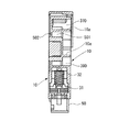
図1は本発明に係る液体収容容器としてのインクカートリッジの外観斜視図であり、図
2は図1のインクカートリッジを図1とは逆の角度からみた外観斜視図である。図3は図
1のインクカートリッジの分解斜視図、図4は図3のインクカートリッジを図3とは逆の
角度からみた分解斜視図である。図5は図1のインクカートリッジをインクジェット式記
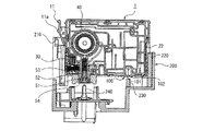
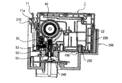
録装置のキャリッジに取り付けた状態を示す図であり、図6はキャリッジへの取付直前の
状態を示す断面図、図7はキャリッジへの取付直後の状態を示す断面図である。
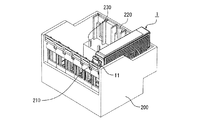
FIG. 1 is an external perspective view of an ink cartridge as a liquid container according to the present invention, and FIG. 2 is an external perspective view of the ink cartridge of FIG. 1 viewed from the opposite angle to FIG. 3 is an exploded perspective view of the ink cartridge of FIG. 1, and FIG. 4 is an exploded perspective view of the ink cartridge of FIG. 3 viewed from an angle opposite to that of FIG. 5 is a view showing a state in which the ink cartridge of FIG. 1 is attached to the carriage of the ink jet recording apparatus, FIG. 6 is a cross-sectional view showing a state immediately before attachment to the carriage, and FIG. 7 is a state immediately after attachment to the carriage. FIG.
本発明によるインクカートリッジ1は、図1及び図2に示すように、略直方体形状を有
し、内部に設けられたインク収容室にインクIを貯留・収納する液体収容容器である。イ
ンクカートリッジ1は、液体消費装置の一例としてのインクジェット式記録装置のキャリ
ッジ200に装着され、当該インクジェット式記録装置にインクIを供給する(図5参照
)。
As shown in FIGS. 1 and 2, the
インクカートリッジ1の外観的特徴について説明すると、図1及び図2に示すように、
インクカートリッジ1は、フラットな上面1aを有し、上面1aに対向する底面1bにイ
ンクジェット式記録装置に接続されてインクIを供給するインク供給孔50が設けられて
いる。また、底面1bには、インクカートリッジ1内部に大気を導入する大気開放孔10
0が開口している。すなわち、インクカートリッジ1は、大気開放孔100から空気を導
入しつつインク供給孔50からインクIを供給する大気開放型のインクカートリッジであ
る。
The appearance characteristics of the
The
0 is open. In other words, the
インクカートリッジ1の大気開放孔100は、図6に示すように、底面1bに底面側か
ら上面側に向けて開口した略円筒形状の凹部101と、凹部101の内周面に開口した小
孔102とを有している。小穴102は、後述の大気連通路に連通しており、この小穴1
02を介して大気が後述の最上流のインク収容室370に導入される。
As shown in FIG. 6, the
The air is introduced into the most upstream
大気開放孔100の凹部101は、キャリッジ200に形成された突起230を受け入
れるような深さに構成されている。この突起230は、大気開放孔100を気密に閉塞す
る閉塞手段としての封止フィルム90の剥がし忘れを防止するための剥離忘れ防止突起で
ある。すなわち、封止フィルム90が貼り付けられた状態では、大気開放孔100内に突
起230が挿入されないため、インクカートリッジ1がキャリッジ200に取り付けられ
ない。これによりユーザが、大気開放孔100上に封止フィルム90が貼り付けたままキ
ャリッジ200にインクカートリッジ1を取り付けようとしても取り付けられないように
することにより、インクカートリッジ1の装着時には確実に封止フィルム90を剥がすよ
うに促すことができる。
The
また、図1に示すように、インクカートリッジ1の上面1aの一つの短辺側に隣り合う
狭側面1cには、インクカートリッジ1が誤った位置に装着されることを防ぐための誤挿
入防止突起22が形成されている。受け手となるキャリッジ200側には、図5に示すよ
うに、誤挿入防止突起22と対応する凹凸220が形成されており、インクカートリッジ
1は誤挿入防止突起22と凹凸220とが干渉しない場合のみキャリッジ200に装着さ
れる。誤挿入防止突起22は、インクIの種類毎に異なる形状を有し、受け手となるキャ
リッジ200側の凹凸220も対応するインクIの種類に応じた形状を有している。した
がって、図5に示すように、キャリッジ200が複数のインクカートリッジを装着可能な
場合でも、誤った位置にインクカートリッジを装着することがない。
Further, as shown in FIG. 1, an erroneous insertion prevention protrusion for preventing the
また、図2に示すように、インクカートリッジ1の狭側面1cと対向する狭側面1dに
は、係合レバー11が設けられている。この係合レバー11は、キャリッジ200への装
着時にキャリッジ200に形成された凹部210と係合する突起11aが形成されており
、係合レバー11が撓みつつ突起11aと凹部210が係合することによりキャリッジ2
00に対してインクカートリッジ1が位置固定される。
Further, as shown in FIG. 2, an
The position of the
また、係合レバー11の下方には、回路基板34が設けられている。この回路基板34
上には、複数の電極端子34aが形成されており、これら電極端子34aがキャリッジ2
00に設けられた電極部材(不図示)と接触することにより、インクカートリッジ1が電
気的にインクジェット式記録装置と接続される。回路基板34には、データ書換可能な不
揮発性メモリが設けられており、インクカートリッジ1に関する各種情報やインクジェッ
ト式記録装置のインク使用情報等が記憶される。また、回路基板34の裏側には、インク
カートリッジ1内のインク残量を、残留振動を利用して検出する液体残量センサ(センサ
ユニット)31(図3または図4参照のこと)が設けられている。以下の説明では、液体
残量センサ31と回路基板34とを合わせてインクエンドセンサ30と呼称することとす
る。
A
A plurality of
By contacting an electrode member (not shown) provided at 00, the
また、インクカートリッジ1の上面1aには、図1に示すように、インクカートリッジ
の中身を示すラベル60aが貼り付けられている。このラベル60aは、広側面1fを覆
う外表面フィルム60の端部が上面1aにまでまたがって貼り付けられることによって形
成されている。
As shown in FIG. 1, a
また、図1及び図2に示すように、インクカートリッジ1の上面1aの2つの長辺側に
隣り合う広側面1e,1fは、フラットな面形状とされている。以下の説明では、便宜上
、広側面1eの側を正面側、広側面1fの側を背面側、狭側面1cの側を右側面側、そし
て狭側面1dの側を左側面側として説明する。
As shown in FIGS. 1 and 2, the
次に、図3及び図4を参照しながら、インクカートリッジ1を構成する各部について説
明する。
Next, each part constituting the
インクカートリッジ1は、容器本体であるカートリッジ本体10と、カートリッジ本体
10の正面側を覆う蓋部材20とを有している。
The
カートリッジ本体10は、その正面側には様々な形状を有するリブ10aが形成されて
おり、これらのリブ10aが仕切を為して、インクIが充填される複数のインク収容室(
液体収容室)、インクIは充填されない未充填室、後述の大気連通路150の途中に位置
する空気室などを、内部に区画形成する。
カートリッジ本体10と蓋部材20との間には、カートリッジ本体10の正面側を覆う
フィルム80が設けられており、このフィルム80によってリブ、凹部、溝の上面が塞が
れて複数の流路やインク収容室、未充填室、空気室が形成される。
The
(Liquid storage chamber), an unfilled chamber not filled with ink I, an air chamber located in the middle of an air communication path 150 (to be described later), and the like are partitioned.
A
またカートリッジ本体10の背面側には、差圧弁40を収容する凹部としての差圧弁収
容室40aと気液分離フィルタ70を構成する凹部としての気液分離室70aとが形成さ
れている。
Further, on the back side of the
差圧弁収容室40aには、バルブ部材41とバネ42とバネ座43とが収納されて差圧
弁40を構成している。差圧弁40は、下流側のインク供給孔50と上流側のインク収容
室との間に配置されており、上流側に対して下流側を減圧することで、インク供給孔50
に供給されるインクIが負圧となるように構成されている。
A valve member 41, a
Is configured such that the ink I supplied thereto has a negative pressure.
気液分離室70aの上面には、気液分離室70aの中央部近傍に設けられた外周を囲む
土手70bに沿って気液分離膜71が貼着されている。この気液分離膜71は、気体を通
過させるとともに液体を通過不可能に遮断する素材であり、全体で気液分離フィルタ70
を構成している。気液分離フィルタ70は、大気開放孔100とインク収容室とを結ぶ大
気連通路150内に設けられており、インク収容室のインクIが大気連通路150を経て
大気開放孔100から流出しないようにするためのものである。
A gas-liquid separation film 71 is attached to the upper surface of the gas-
Is configured. The gas-
カートリッジ本体10の背面側には、差圧弁収容室40aと気液分離室70a以外にも
複数の溝10bが刻まれている。これらの溝10bは、差圧弁40と気液分離フィルタ7
0が構成された状態で外表面を外表面フィルム60が覆うことにより各溝10bの開口部
が塞がれ、大気連通路150やインク誘導路が形成される。
In addition to the differential pressure
When the
カートリッジ本体10の右側面側には、図4に示すように、インクエンドセンサ30を
構成する各部材を収納する凹部としてセンサ室30aが形成されている。このセンサ室3
0aには、液体残量センサ31と、液体残量センサ31をセンサ室30aの内壁面に押し
つけて固定する圧縮バネ32とが収納される。また、センサ室30aの開口部はカバー部
材33によって覆われ、このカバー部材33の外表面33a上に回路基板34が固定され
る。液体残量センサ31のセンシング部材は回路基板34と接続されている。
As shown in FIG. 4, a
In 0a, a remaining
液体残量センサ31は、インク収容室からインク供給孔50との間のインク誘導路の一
部を形成するキャビティと、このキャビティの壁面の一部を形成する振動板と、この振動
板上に振動を印加させる圧電素子(圧電アクチュエータ)とを備えて、前記振動板に振動
を印加した際の残留振動から前記インク誘導路内におけるインクIの有無を検出する。こ
の液体残量センサ31は、インクIと気体(インクIに混入した気泡)との間での残留振動
の振幅、周波数等の違いを検出して、カートリッジ本体10内におけるインクIの有無を
検出する。
具体的には、カートリッジ本体10内のインク収容室のインクIが消尽されて、インク
収容室内に導入された大気がインク誘導路を伝って、液体残量センサ31のキャビティ内
に進入すると、その時の残留振動の振幅や周波数の変化から、その旨を検知し、インクエ
ンドを示す電気信号を出力する。
The liquid remaining
Specifically, when the ink I in the ink storage chamber in the
カートリッジ本体10の底面側には、先ほど説明したインク供給孔50と大気開放孔1
00以外に、図4に示すように、インク注入時に真空引き手段を介してインクカートリッ
ジ1内部から空気を吸い出して減圧に用いられる減圧孔110と、インク収容室からイン
ク供給孔50に至るインク誘導路を構成する凹部95aと、インクエンドセンサ30の下
方に設けられたバッファ室30bとが形成されている。
On the bottom surface side of the
In addition to 00, as shown in FIG. 4, when the ink is injected, air is sucked out from the inside of the
インク供給孔50、大気開放孔100、減圧孔110、凹部95a、及びバッファ室3
0bは、インクカートリッジ製造直後には、全てそれぞれ封止フィルム54,90,98
,95,35によってそれぞれの開口部が封止された状態となっている。このうち、大気
開放孔100を封止する封止フィルム90は、インクカートリッジをインクジェット式記
録装置に装着して使用状態とする前にユーザによって剥離される。これにより、大気開放
孔100が外部に露出し、インクカートリッジ1内部のインク収容室が大気連通路150
を介して外気と連通する。
0b is the sealing
, 95, and 35, the respective openings are sealed. Among these, the sealing
Communicate with the outside air through
また、インク供給孔50の外表面に貼り付けられた封止フィルム35は、図6及び図7
に示すように、インクジェット式記録装置への装着時にインクジェット式記録装置側のイ
ンク供給針240によって破られるように構成されている。
Further, the sealing
As shown in FIG. 4, the
インク供給孔50の内部には、図6及び図7に示すように、装着時にインク供給針の2
40の外表面に押しつけられる環状のシール部材51と、プリンタに装着されていない場
合はシール部材51と当接してインク供給孔50を閉塞するバネ座52と、バネ座52を
シール部材51の当接方向に付勢する圧縮バネ53とを備えている。
Inside the
An
図6及び図7に示すように、インク供給針240がインク供給孔50内に挿入されると
、シール部材51の内周とインク供給針240の外周がシールされ、インク供給孔50と
インク供給針240との間の隙間が液密に封止される。また、インク供給針51の先端が
バネ座52と当接し、バネ座52を上に押し上げ、バネ座52とシール部材51のシール
が解除されることにより、インク供給孔50からインク供給針240にインクIが供給可
能となる。
6 and 7, when the
次に、図8〜図12を参照しながら、上記インクカートリッジ1の内部構造について説
明する。
Next, the internal structure of the
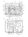
図8はインクカートリッジ1のカートリッジ本体10を正面側から見た図であり、図9
はインクカートリッジ1のカートリッジ本体10を背面側から見た図であり、図10の(
a)は図8の簡略模式図であり、図10の(b)は図9の簡略模式図であり、図11は図
8のA−A断面図である。また、図12は図8に示した流路の一部拡大斜視図である。
8 is a view of the cartridge
FIG. 10 is a view of the
8 is a simplified schematic diagram of FIG. 8, FIG. 10B is a simplified schematic diagram of FIG. 9, and FIG. 11 is a cross-sectional view taken along line AA of FIG. FIG. 12 is a partially enlarged perspective view of the flow path shown in FIG.
上記インクカートリッジ1では、インクIが充填される主なインク収容室として、上下
2つに分断された上部インク収容室370及び下部インク収容室390と、これらの上下
のインク収容室に挟まれるように位置するバッファ室430との3つのインク収容室が、
カートリッジ本体10の正面側に形成されている。
また、カートリッジ本体10の背面側には、インクIの消費量に応じて、大気を最上流
のインク収容室である上部インク収容室370に導入する大気連通路150が形成されて
いる。
In the
It is formed on the front side of the
In addition, an
インク収容室370,390及びバッファ室430は、リブ10aにより区分されてい
る。そして、これらの各インク収容室は、水平方向に延在して収容室の底壁となるリブ1
0aの一部に、下方に窪ませた形状の窪み374,394,434が形成されている。
窪み374は、上部インク収容室370のリブ10aによる底壁375の一部を下方に
窪ませたものである。窪み394は、下部インク収容室390のリブ10aによる底壁3
95と壁面の膨出部によりカートリッジ厚さ方向に窪ませたものである。窪み434は、
バッファ室430の10aによる底壁435の一部を下方に窪ませたものである。
The
The
95 and a bulging portion of the wall surface, which is recessed in the cartridge thickness direction. The
A part of the
そして、各窪み374,394,434の底部又はその付近には、インク誘導路380
,420,440に連通するインク排出口371,312,432が設けられている。
インク排出口371,432は、各インク収容室の壁面をカートリッジ本体10の厚さ
方向に貫通した貫通孔である。また、インク排出口312は、液体残量センサ31内のキ
ャビティ(流路)の出口である。
An
, 420, and 440,
The
インク誘導路380は、一端が上部インク収容室370のインク排出口371に連通す
ると共に、他端が下部インク収容室390に設けられたインク流入口391に連通してお
り、上部インク収容室370のインクIを下部インク収容室390に誘導する連絡流路と
なっている。このインク誘導路380は、上部インク収容室370のインク排出口371
から鉛直下方に延びた形態で設けられており、連絡流路内での液体の流れ方向が上から下
への降下流となる降下型接続で一対の液体収容室370,390相互を接続している。
One end of the
A pair of
インク誘導路420は、一端が下部インク収容室390の下流に位置する液体残量セン
サ31内のキャビティのインク排出口312に連通すると共に、他端がバッファ室430
に設けられたインク流入口431に連通しており、下部インク収容室390のインクIを
バッファ室430に誘導する。このインク誘導路420は、液体残量センサ31内のキャ
ビティのインク排出口312から斜め上方に延びた形態で設けられており、連絡流路内で
の液体の流れ方向が下から上への上昇流となる上昇型接続で一対のインク収容室390,
430相互を接続している。
One end of the
Are connected to the
430 are connected to each other.
即ち、上記カートリッジ本体10では、3個のインク収容室370,390,430相
互は、降下型接続と、上昇型接続とが交互に並ぶ直列状に接続されている。
That is, in the cartridge
インク誘導路440は、バッファ室430のインク排出口432から差圧弁40にイン
クIを誘導するインク流路である。
The
上記の各インク収容室のインク流入口391,431は、いずれも、各インク収容室に
おいて、それぞれの収容室に設けられたインク排出口371,312よりも上方で、各イ
ンク収容室の底壁375,395,435の近傍に設けられている。
The
以下、まず主たるインク収容室である上部インク収容室370からインク供給孔50に
至るまでのインク誘導路を図8〜図12を参照しながら説明する。
Hereinafter, an ink guiding path from the upper
上部インク収容室370は、カートリッジ本体10内の最上流(最上位)のインク収容
室で、図8に示すように、カートリッジ本体10の正面側に形成されている。この上部イ
ンク収容室370は、インク収容室の約半分を占めるインク収容領域であり、カートリッ
ジ本体10の略半分から上の部分に形成されている。上部インク収容室370の底壁の窪
み374には、インク誘導路380と連通するインク排出口371が開口している。この
インク排出口371は、上部インク収容室370の底壁となっているリブ10aのよりも
下がった位置にあり、上部インク収容室370内のインク液面が底壁まで下がっても、そ
の時の液面よりも下方に位置して、安定したインクIの導出を継続する。
The upper
インク誘導路380は、図9に示すように、カートリッジ本体10の背面側に形成され
上方からインクIを下方の下部インク収容室390に導く。
As shown in FIG. 9, the
下部インク収容室390は、上部インク収容室370に貯留されているインクIが導入
されるインク収容室で、図8に示すように、カートリッジ本体10の正面側に形成される
インク収容室の約半分を占めるインク収容領域であり、カートリッジ本体10の略半分か
ら下の部分に形成されている。この下部インク収容室390の底壁となっているリブ10
aの近傍に、インク誘導路380と連通するインク流入口391は、下部インク収容室3
90の底壁395の下方に配置された連通流路に開口しており、該連通流路を介して上部
インク収容室370からのインクIが流入する。
The lower
In the vicinity of a, an
The ink I from the upper
下部インク収容室390は、底壁395を貫通したインク排出口311により上流側イ
ンクエンドセンサ連絡流路400に連通している。上流側インクエンドセンサ連絡流路4
00には、三次元的に形成された迷路流路が形成されており、この迷路流路にてインクエ
ンド前に流入した気泡B等を捕捉して下流側に流れないように構成されている。
The
In 00, a maze channel formed in a three-dimensional manner is formed, and the maze channel is configured to capture bubbles B and the like that have flowed in before the ink end and do not flow downstream. .
上流側インクエンドセンサ連絡流路400は、図示せぬ貫通孔を介して下流側インクエ
ンドセンサ連絡流路410に連通しており、下流側インクエンドセンサ連絡流路410を
介してインクIが液体残量センサ31に導かれる。
The upstream side ink end
液体残量センサ31に導かれたインクIは、液体残量センサ31内のキャビティ(流路
)を通って、キャビティの出口であるインク排出口312からカートリッジ本体10の背
面側に形成されたインク誘導路420に導かれる。インク誘導路420は、液体残量セン
サ31から斜め上方にインクIを導くように形成されており、バッファ室430と連通す
るインク流入口431に接続されている。これにより、液体残量センサ31を出たインク
Iは、インク誘導路420を経てバッファ室430に導かれる。
The ink I guided to the liquid remaining
I is guided to the
バッファ室430は、上部インク収容室370と下部インク収容室390との間にリブ
10aにより区画形成された小部屋であり、差圧弁40の直前のインク貯留空間として形
成されている。バッファ室430は、差圧弁40の裏側に対向するように形成されており
、バッファ室430の窪み434に形成されたインク排出口432が連通したインク誘導
路440を介して差圧弁40にインクIが流入する。
The
差圧弁40に流入したインクIは、差圧弁40によって下流側に導かれ、貫通孔451
を介して出口流路450に導かれる。出口流路450は、インク供給孔50に連通してお
り、インク供給孔50に差し込まれたインク供給針240を介してインクIがインクジェ
ット式記録装置側に供給される。
The ink I that has flowed into the
To the
なお、上記インクカートリッジ1の場合、図8にも示したように、カートリッジ本体1
0の正面側には、前述のインク収容室(上部インク収容室370,390、バッファ室4
30)や、空気室(インクトラップ室340、連絡バッファ室350)や、インク誘導路
(上流側インクエンドセンサ連絡流路400、下流側インクエンドセンサ連絡流路410
)の他に、インクIが充填されない未充填室501が画成されている。
In the case of the
On the front side of 0, the above-described ink storage chambers (upper
30), an air chamber (
In addition, an
未充填室501は、カートリッジ本体10の正面側で、左側面寄りのハッチングを施し
た領域で、上部インク収容室370と下部インク収容室390とに挟まれるように画成さ
れている。
そして、この未充填室501は、その内部領域の左上隅に、背面側に貫通した大気開放
孔502が設けられ、該大気開放孔502により外気に連通している。
この未充填室501は、インクカートリッジ1を減圧パック包装した時に、脱気用負圧
を蓄圧した脱気室となる。
The
The
The
次に、大気開放孔100から上部インク収容室370に至るまでの大気連通路150を
図8〜図12を参照しながら説明する。
Next, the
インクカートリッジ1内のインクIが消費されてインクカートリッジ1内部の圧力が低
下すると、貯留しているインクIの減少分だけ大気開放孔100から大気(空気)が上部
インク収容室370に流入する。
When the ink I in the
大気開放孔100の内部に設けられた小穴102は、カートリッジ本体10の背面側に
形成された蛇道310の一端に連通している。蛇道310は、大気開放孔100から上部
インク収容室370までの距離を長くしインク中の水分の蒸発を抑制するように細長く形
成された蛇行路である。蛇道310の他端は、気液分離フィルタ70に接続されている。
A
気液分離フィルタ70を構成する気液分離室70aの底面には、貫通孔322が形成さ
れており、貫通孔322を介してカートリッジ本体10の正面側に形成された空間320
に連通している。気液分離フィルタ70においては、貫通孔322と蛇道310の他端と
の間に気液分離膜71が配置される。気液分離膜71は撥水性および撥油性の高い繊維材
料をメッシュ状に編みこんだもので形成される。
A through-
Communicating with In the gas-
空間320は、カートリッジ本体10の正面側からみて上部インク室の右上方に形成さ
れている。空間320には、貫通孔322の上部に貫通孔321が開口している。空間3
20は、この貫通孔321を介して背面側に形成された上部連結流路330に連通してい
る。
The
20 communicates with the
上部連結流路330は、インクカートリッジ1の最も上面側、すなわちインクカートリ
ッジ1が取り付けられた状態における重力方向で最も上となる部分を通過するように、背
面側から見て貫通孔321から長辺に沿って右方向に延びる流路部分333と、短辺近傍
の折り返し部335で折り返して流路部分333よりもインクカートリッジ1の上面側を
通って貫通孔321の近傍に形成された貫通孔341まで延びる流路部分337とを有し
ている。なお、貫通孔341は、正面側に形成されたインクトラップ室340に連通して
いる。
The upper connecting
ここで、背面側からこの上部連結流路330を見ると、折り返し部335から貫通孔3
41までの延びる流路部分337には、貫通孔341が形成された位置336と、位置3
36よりカートリッジ厚さ方向位置が深く掘り下げられた凹部332が設けられており、
この凹部332を区切るようにリブ331が複数形成されている。また、貫通孔321か
ら折り返し部335まで延びる流路部分333は、折り返し部335から貫通孔341ま
での延びる流路部分337よりも深さが浅く形成されている。
Here, when the upper
In the
36 is provided with a
A plurality of
この例では、上部連結流路330を重力方向で最も上となる部分に形成することで、基
本的にはインクIが上部連結流路330を超えて大気開放孔100側に移動しないように
構成されている。また、上部連結流路330は、毛細管現象等によりインクIの逆流が発
生しない程度に幅広の太さを有するとともに、流路部分337には凹部332が形成され
ているので逆流してきたインクIを捕捉しやすく構成されている。
In this example, the
インクトラップ室340は、正面側から見てカートリッジ本体10の右上方の隅の位置
に形成された直方体形状の空間である。貫通孔341は、図12に示すように、正面側か
ら見てインクトラップ室340の左上方奥側隅部近傍に開口している。また、インクトラップ室340の右下方手前側隅部には、仕切となるリブ10aの一部が切り欠かれた切り欠き部342が形成されており、この切り欠き部342を介して連絡バッファ室350に連通している。ここで、インクトラップ室340および連絡バッファ室350は、大気連通路150の途中の容積を拡張した形態の空気室で、何らかの理由により上部インク収容室370からインクIが逆流した場合でもこのインクトラップ室340および連絡バッファ室350にインクIを留め、これ以上大気開放孔100側へなるべく流れ込まないように構成されたものである。具体的なインクトラップ室340および連絡バッファ室350の役割については後述する。
The
連絡バッファ室350は、インクトラップ室340の下方に形成された空間である。連
結バッファ室350の底面352にはインク注入時に空気抜きを行うための減圧孔110
が設けられている。また、底面352近傍であってインクジェット式記録装置への装着時
最も重力方向下方の部位には厚さ方向側に貫通孔351が開口しており、この貫通孔35
1を介して背面側に形成された細い連通路360に連通している。
The
Is provided. In addition, a through
1 is communicated with a
細い連通路360は、上部インク収容室370を大気開放孔100に連通させる大気連
通路150の一部を成すもので、図10(b)に示すように、背面側から見て中央上方側
に延びており、上部インク収容室370の底面近傍に開口した貫通孔372を介して上部
インク収容室370と連通している。
細い連通路360の一端の貫通孔372は、大気連通路150を介して外気を上部イン
ク収容室370内に導入する大気流出口である。また、細い連通路360の他端の貫通孔
351は、連絡バッファ室350に連通しており、連絡バッファ室350から細い連通路
360に外気を導入させる大気流入口である。
The
The through
上記の細い連通路360では、その一端の大気流出口である貫通孔372が、最上流の
上部インク収容室370の底壁375(図10(a)参照)の近傍に設けられ、更に、他
端の大気流入口である貫通孔351が上部インク収容室370の底壁375よりも距離H
1だけ下方に設けられている。
In the
1 is provided below.
細い連通路360は、図10(b)に示すように、大気流出口である貫通孔372から
略垂直に距離H1だけ降下する第1連通路361と、この第1連通路361の下端から略
水平に距離L1だけ延出して大気流入口である貫通孔351に連通する第2連通路362
とによって、略L字形状に形成されている。
As shown in FIG. 10B, the
Are formed in a substantially L shape.
第1連通路361と第2連通路362とにより略L字形状に形成された細い連通路36
0は、大気連通路150を構成する他の連通路部分よりも流路断面が細く形成された連通
路で、上部インク収容室370に収容されているインクIの一部を通路のメニスカスによ
り第1連通路361及び第2連通路362内に保持している。
連通路360は全ての部分においてメニスカスを形成できる程度に細いので、温度変化
などで上部インク収納室370内部の空気が膨張ないし収縮し、連通路360内で形成さ
れている液面が移動した場合においても、連通路360内のいずれかの場所でメニスカス
を形成できる。
また、細い連通路360の内部に保持されるインク量が、上部インク収容室370に収
容されているインクIを外部の大気から遮断可能な適当量となるように、前述の第1連通
路361の長さH1や第2連通路362の長さL1が設定されている。
A narrow communication path 36 formed in a substantially L shape by the
0 is a communication path having a channel cross-section narrower than the other communication path portions constituting the
Since the
In addition, the
以上に説明したインクカートリッジ1では、大気連通路150は、その途中に設けられ
た細い連通路360の部分に保持されたインクIにより液封されているため、上部インク
収容室370に貯留されているインク中の水分が大気連通路150から外部に蒸発するこ
とがなく、水分の蒸発によるインクIの粘度上昇を防止できる。また、細い連通路360
における液封は、上部インク収容室370内のインクIの消費により上部インク収容室3
70内の気圧が下がると、外部の大気を微少な気泡状態にして液封しているインク中を通
過させて上部インク収容室370内に導入し、上部インク収容室370内の気圧を大気圧
に戻すが、上部インク収容室370内の気圧が下がらないときは外部の大気が導入される
ことがない。
即ち、大気連通路150を介したインク収容室370内のへの大気の流入が必要最小限
に規制されるため、インクIと新鮮な空気との接触によるインクIの品質劣化を抑えること
ができる。
従って、各インク収容室370,390,430に貯留しているインクIの品質をより
長期に渡って、安定維持することができる。
In the
The liquid sealing in the upper ink storage chamber 3 is caused by the consumption of the ink I in the upper
When the atmospheric pressure in 70 decreases, the outside air is made into a fine bubble state and passed through the liquid-sealed ink and introduced into the upper
That is, since the inflow of the atmosphere into the
Therefore, the quality of the ink I stored in each
また、上記のインクカートリッジ1の場合、液封を行う細い連通路360は、一端の大
気流出口である貫通孔372が、上部インク収容室370の底壁375の近傍に設けられ
、他端の大気流入口である貫通孔351が、上部インク収容室370の底壁375よりも
距離H1だけ下方に設けられている。
そのため、例えば、工場等でカートリッジ本体10内に所定量のインクIを充填した時
に、大気流出口に作用する上部インク収容室370内のインクIの液圧で、細い連通路3
60の部分に必要量のインクIを送給して保持させることができ、大気連通路150の途
中の液封部の形成が容易にできる。
Further, in the case of the
Therefore, for example, when a predetermined amount of ink I is filled in the cartridge
The required amount of ink I can be fed and held in the
また、上記のインクカートリッジ1の場合、細い連通路360の部分が、略L字形状に
形成されているため、細い連通路360の部分に貯留された封止用のインクIに対して、
略L字形状の屈曲部で発生するメニスカス力が、インクIの移動(逆流)を規制する保持
力を発揮し、細い連通路360の部分にインクIを保持した液封状態をより長期にわたっ
て安定維持することができる。
In the case of the
The meniscus force generated in the substantially L-shaped bent portion exerts a holding force that restricts the movement (back flow) of the ink I, and the liquid sealed state in which the ink I is held in the
なお、上記のインクカートリッジ1では、一つのカートリッジ本体内に3個のインク収
容室を区画形成しているが、カートリッジ本体内に装備するインク収容室の数量は、3個
以上の任意数に設定でき、インク収容室の装備数が増えるほど、気泡トラップが多重化さ
れて、気泡Bの下流への移動を阻止する性能が向上する。
In the
次に、以上に説明したインクカートリッジ1内のインクIが消尽された場合に、その使
用済みのインクカートリッジ1にインクIを注入する方法の一実施の形態を、図13〜図
14に基づいて説明する。
Next, an embodiment of a method for injecting ink I into the used
まず、本実施の形態の注入方法で使用するインク再注入装置の構成について説明する。
インク再注入装置600は、図13に示すように、カートリッジ本体10に穿孔加工に
より開けた注入口601に接続されるインク注入手段610と、カートリッジ本体10の
インク供給孔50に接続される真空吸引手段620とから構成されている。
First, the configuration of the ink re-injection apparatus used in the injection method of the present embodiment will be described.
As shown in FIG. 13, the
インク注入手段610は、充填するインクIを貯留したインクタンク611と、このイ
ンクタンク611内のインクIを前記注入口601に接続された流路612に圧送するポ
ンプ613と、このポンプ613と注入口601との間で流路612を開閉するバルブ6
14とを備えている。
The ink injection means 610 includes an
14.
真空吸引手段620は、真空吸引に必要な負圧を発生する真空ポンプ621と、この真
空ポンプ621の発生する負圧をインク供給孔50に作用させる連絡流路622と、連絡
流路622の途中に装備されて真空吸引によりカートリッジ本体10側から連絡流路62
2に流入してきたインクIを捕捉・回収して、インクミスト等から真空ポンプ621を保
護するインクトラップ623と、このインクトラップ623とインク供給孔50との間で
連絡流路622を開閉するバルブ624とを備えている。
The vacuum suction means 620 includes a
The
本実施の形態では、カートリッジ本体10の構造や機能を配慮し、カートリッジ本体1
0への穿孔加工により形成する注入口601の位置は、大気連通路150の一部を構成す
る細い連通路360の上流端に位置する貫通孔351に連通するように装備される。
貫通孔351に連通する注入口601は、次のようにして形成する。
まず、インクカートリッジ1から蓋部材20を採りはずして、カートリッジ本体10の
正面側に溶着されているフィルム80を露出させる。そして、貫通孔351に一致するよ
うに、フィルム80に孔を開けることで、形成する。なお、該注入口601に挿入される
流路612の先端部は、例えば、貫通孔351に押し当てると、貫通孔351の周囲の容
器壁面に気密に密着して、流路612と細い連通路360とを気密な接続状態とするシー
ルリング等が設けられている。
In the present embodiment, the structure and function of the
The position of the
The
First, the
なお、カートリッジ本体10上の注入口601は、細い連通路360の上流端より上流
で大気連通路150に連通すれば良く、注入口601の装備位置は、上記実施の形態に限
らない。
例えば、図14に示すように、気液分離フィルタ70を構成する気液分離室70aに開
口する貫通孔322に対向する位置P1に設定しても良い。この場合は、気液分離フィル
タ70を構成する気液分離膜71を剥がして、貫通孔322に流路612を接続すること
になる。
The
For example, as shown in FIG. 14, it may be set at a position P <b> 1 facing the through
本実施の形態では、まず、細い連通路360の部分の上流端より上流で大気連通路15
0に連通する注入口601をカートリッジ本体10に開口させる注入口形成工程と、イン
ク供給孔50から内部に残留するインク及び残留気体を真空吸引手段620により吸引除
去する真空吸引工程と、注入口601からインク注入手段610により所定量のインクI
を注入する液体充填工程と、液体充填工程の終了後に注入口601を封止する封止工程と
、を順に実施することで、使用済みのインクカートリッジ1を、再び使用可能なインクカ
ートリッジ(液体収容容器)として復活させる。
上記真空吸引工程と液体充填工程は、上記のように吸引工程を行った後、減圧状態を維
持した工程を間において、続いて液体を充填するような工程をとる事も可能である。
また、真空吸引工程の途中で、液体充填工程を開始するような工程や、真空吸引工程を
行いながら、液体充填工程を行う工程をとる事も可能である。
液体充填工程においては、具体的には、真空吸引工程を開始する時には、インク注入手
段610の注入口601から流路612の間が注入前に吸引工程に同期して減圧状態に置
かれるように開閉バルブ614を閉状態にし、その後、開閉バルブ614を開くことで、
上記のような、1.真空吸引工程と充填工程を順次行う場合、2.真空吸引工程と充填工程を
一部重複する工程として行う場合、3.真空吸引工程を行いながらほぼ同期して充填工程を
行う場合等、で液体充填を空気の取り込みをきわめて少なくし短時間で行うことが可能と
なり、再生カートリッジの品質を落とす事が無いようにする事が出来る。
また更に、再充填するインクIの脱気度が高く(溶存空気、溶存気体の割合が少ない)
管理されたインクの場合には、真空吸引手段620をコントロールし、液体充填工程のイ
ンク注入速度をゆっくりとする事でより気泡の取り込みのない液体充填を可能にすること
で、再生カートリッジの品質を落とす事が無いようにする事も出来る。
In the present embodiment, first, the atmospheric communication passage 15 is located upstream from the upstream end of the portion of the
An injection port forming step for opening the
The liquid filling step for injecting the liquid and the sealing step for sealing the
The vacuum suction step and the liquid filling step can be performed by filling the liquid subsequently after the suction step is performed as described above and after the step of maintaining the reduced pressure state.
Further, it is possible to take a process of starting the liquid filling process in the middle of the vacuum suction process or a process of performing the liquid filling process while performing the vacuum suction process.
In the liquid filling process, specifically, when starting the vacuum suction process, the space between the
1. When performing the vacuum suction process and the filling process sequentially, 2. When performing the vacuum suction process and the filling process as partly overlapping processes, 3. When filling the vacuum process almost synchronously In this case, the liquid filling can be performed in a short time with very little intake of air, so that the quality of the reproduction cartridge can be prevented from being deteriorated.
Furthermore, the degree of deaeration of ink I to be refilled is high (the ratio of dissolved air and dissolved gas is small).
In the case of controlled ink, the vacuum suction means 620 is controlled, and the ink filling speed in the liquid filling process is made slow to enable liquid filling without taking in air bubbles, thereby improving the quality of the reproduction cartridge. You can make sure that you don't drop it.
封止工程は、具体的には、注入口601を、封止フィルムの接着,溶着等で気密に塞ぐ
処理工程である。また、回収時のカートリッジ状態や再生処理時の注入口601の状態か
ら、封止フイルムの接着,溶着等で気密に塞ぐことが困難である場合には、気密に塞ぐこ
とを可能とするフイルム以外の封止材料(軟質樹脂材料、接着剤等)を利用する事もでき
る。
更に、封止工程を終えた再生カートリッジを、遮気性素材(遮気性フイルムや遮気性金
属材料、アルミ素材等)でパックする工程を加える事も可能であり、このようにして製造
した再生インクカートリッジは、それが再び流通過程を経て消費者の下に届くまで、直接
流通過程下の環境に触れる事が無い為、より安定した再生品質を維持する事が可能となる
。更に、遮気性素材のパック内の空気を脱気した状態で再生カートリッジをパックするこ
とでより安定した再生品質を維持する事が可能となる。
Specifically, the sealing step is a processing step of sealing the
Furthermore, it is also possible to add a process of packing the regenerated cartridge after the sealing process with an airtight material (airtight film, airtight metal material, aluminum material, etc.), and the regenerated ink cartridge manufactured in this way Since it does not touch the environment directly under the distribution process until it reaches the consumer through the distribution process again, more stable reproduction quality can be maintained. Furthermore, it is possible to maintain a more stable reproduction quality by packing the reproduction cartridge in a state where the air in the pack of the airtight material is deaerated.
以上に説明した本実施の形態では、インクIの注入のためにカートリッジ本体10に実
施する加工は、細い連通路360の部分の上流端より上流で大気連通路150に連通する
ように、インクを注入するための注入口601を開口させることと、インクIの充填後に
、注入口601を封止する加工で、いずれも簡単な加工となる。従って加工コストが安価
で済み、また、手間もかからない。
In the present embodiment described above, the processing performed on the cartridge
そして、本実施の形態では、インク供給孔50から内部に残留するインク及び残留気体
を吸引除去する真空吸引工程を備えているため、注入口601から所定量のインクを注入
する液体充填工程は、カートリッジ本体10の各インク誘導路380,420,440や
各インク収容室を減圧環境に管理して、注入したインクを、インク収容室370,390
,430だけでなく、インク供給孔50に至るすべてのインク誘導路の隅々まで、効率よ
く充填できる。
In this embodiment, since a vacuum suction process for sucking and removing ink and residual gas remaining from the
, 430 as well as every corner of all ink guiding paths leading to the
また、インクIの充填時に混入する気泡も、真空吸引によりインク供給孔50から外部
に排除したり、あるいは真空吸引により形成する容器内の減圧環境により、流入した気泡
を液中に溶解・消滅させることができる。
従って、インクIの注入時に混入する気泡が、インク収容室やインク誘導路に浮遊した
り、あるいは流路壁面に付着して残存することがなく、例えば、液体残量センサの検出部
付近に気泡が残存することにより液体残量センサが正常に作動しなくなるといった不都合
も生じない。
Also, air bubbles mixed during the filling of the ink I are removed from the
Therefore, bubbles that are mixed during the injection of the ink I do not float in the ink storage chamber or the ink guide path or do not remain attached to the wall surface of the flow path. Therefore, there is no inconvenience that the liquid remaining amount sensor does not operate normally due to the remaining of water.
また、注入口601を設ける位置が、大気連通路150の一部の細い連通路360の部
分の上流であることから、この細い連通路360の部分にも、インクを注入することがで
きる。
大気連通路150中の細い連通路360の部分に充填されたインクは、インク収容室3
70内のインクと大気連通路150の外部の大気との間を遮断して、インク収容室370
内のインクIの外気との接触を必要最小限に抑えることで、インクIの劣化を防止するもの
で、このような細い連通路360の部分に託された機能(貯留されているインク中の水分
の蒸発防止など)も、容器の新規製造時と同様に、復活させることができる。
即ち、上記構成によれば、使用済みのインクカートリッジ1にインクを注入する際に、
カートリッジ本体10への加工が少なくて済み、しかも、そのインクカートリッジ1の諸
機能を損なうことなくインクを注入することができ、使用済みのインクカートリッジ1を
安価に利用することができる。
In addition, since the position where the
The ink filled in the
The ink in the
The ink I is prevented from deteriorating by minimizing the contact of the ink I with the outside air, and the function entrusted to such a portion of the narrow communication path 360 (in the stored ink) The prevention of water evaporation, etc.) can be restored as in the case of new production of the container.
That is, according to the above configuration, when ink is injected into the used
Less processing is required for the
そして、このようなインクカートリッジを提供すれば、インクカートリッジの容器とし
ての製品寿命が延びるため、資源の節約、環境汚染の防止に貢献することができる。また
、コストが低く、安価に提供できるため、インクジェット式記録装置の運用コストの低下
にも貢献する。
Providing such an ink cartridge extends the product life of the ink cartridge as a container, thereby contributing to resource conservation and prevention of environmental pollution. In addition, since the cost is low and it can be provided at a low cost, it contributes to a reduction in the operation cost of the ink jet recording apparatus.
本実施の形態を実施する際に使用するインク再注入装置600は、具体的には、入手が
容易な器具を代用することもできる。
例えば、インク注入手段610の場合、注射器の用にシリンダとピストンで構成される
注入器を代用したり、変形可能なペットボトルに補充インクを収容した補充ボトルを代用
することもできる。
Specifically, the
For example, in the case of the ink injection means 610, an injector composed of a cylinder and a piston can be substituted for the syringe, or a refill bottle containing refill ink in a deformable PET bottle can be substituted.
また、本発明による液体収容容器は、上記実施形態に示したインクカートリッジに限ら
ない。また、本発明による液体収容容器が装着される容器装着部を備えた液体消費装置も
、上記実施形態に示したインクジェット式記録装置に限らない。
液体消費装置としては、液体収容容器が着脱可能に装着される容器装着部を備え、前記
液体収容容器に貯留されている液体が装置に供給される各種の装置が該当し、具体例とし
ては、例えば液晶ディスプレー等のカラーフィルタ製造に用いられる色材噴射ヘッドを備
えた装置、有機ELディスプレー、面発光ディスプレー(FED)等の電極形成に用いら
れる電極材(導電ペースト)噴射ヘッドを備えた装置、バイオチップ製造に用いられる生
体有機物噴射ヘッドを備えた装置、精密ピペットとしての試料噴射ヘッドを備えた装置等
が挙げられる。
The liquid container according to the present invention is not limited to the ink cartridge shown in the above embodiment. Further, the liquid consuming apparatus provided with the container mounting portion on which the liquid container according to the present invention is mounted is not limited to the ink jet recording apparatus shown in the above embodiment.
The liquid consuming device includes a container mounting portion on which a liquid storage container is detachably mounted, and various devices in which the liquid stored in the liquid storage container is supplied to the device are applicable. For example, an apparatus having a color material ejecting head used for manufacturing a color filter such as a liquid crystal display, an apparatus having an electrode material (conductive paste) ejecting head used for forming an electrode such as an organic EL display and a surface emitting display (FED), Examples thereof include an apparatus equipped with a bio-organic matter ejecting head used for biochip manufacturing, an apparatus equipped with a sample ejecting head as a precision pipette, and the like.
1:インクカートリッジ(液体収容容器)、10:カートリッジ本体(容器本体)、11
:係合レバー、20:蓋部材、30:インクエンドセンサ、31:液体残量センサ、40
:差圧弁、50:インク供給孔(液体供給孔)、70:気液分離フィルタ、80:フィル
ム、90:封止フィルム(閉塞手段)、100:大気開放孔、150:大気連通路、22
0:キャリッジ、330:上部連結流路、340:インクトラップ室(空気室)、350
:連結バッファ室(空気室)、351:貫通孔(大気流入口)、370:上部インク収容
室(液体収容室)、360:細い連通路、361:第1連通路、362:第2連通路、3
71,432:インク排出口(液体排出口)、372:貫通孔(大気流出口)、374,
394,434:窪み、375,395,435:液体収容室の底壁、380:インク誘
導路(液体誘導路)、390:下部インク収容室(液体収容室)、391,431:イン
ク流入口(液体流入口):400:上流側インクエンドセンサ連絡流路(液体誘導路)、
410:下流側インクエンドセンサ連絡流路(液体誘導路)、420:インク誘導路(液
体誘導路)、430:バッファ室(液体収容室)、501,511,512,521:未
充填室(脱気室)、600:インク再注入装置、601:注入口、610:インク注入手
段、620:真空吸引手段
1: ink cartridge (liquid container), 10: cartridge body (container body), 11
: Engagement lever, 20: lid member, 30: ink end sensor, 31: remaining liquid sensor, 40
: Differential pressure valve, 50: ink supply hole (liquid supply hole), 70: gas-liquid separation filter, 80: film, 90: sealing film (blocking means), 100: atmosphere opening hole, 150: atmosphere communication path, 22
0: carriage, 330: upper connection flow path, 340: ink trap chamber (air chamber), 350
: Connection buffer chamber (air chamber), 351: through hole (atmospheric inlet), 370: upper ink storage chamber (liquid storage chamber), 360: narrow communication path, 361: first communication path, 362: second communication path 3
71,432: Ink discharge port (liquid discharge port), 372: Through hole (atmospheric outlet), 374
394, 434: depression, 375, 395, 435: bottom wall of liquid storage chamber, 380: ink guide path (liquid guide path), 390: lower ink storage chamber (liquid storage chamber), 391, 431: ink inlet ( (Liquid inlet): 400: upstream ink end sensor communication channel (liquid guide channel),
410: downstream ink end sensor communication channel (liquid guide channel), 420: ink guide channel (liquid guide channel), 430: buffer chamber (liquid storage chamber), 501, 511, 512, 521: unfilled chamber (de-filled) Air chamber), 600: ink re-injection device, 601: injection port, 610: ink injection means, 620: vacuum suction means
Claims (5)
液体を収容する液体収容室と、
前記液体消費装置に接続される液体供給孔と、
前記液体収容室に収容される液体を前記液体供給孔に誘導する液体誘導路と、
前記液体収容室内の液体の消費に伴って大気開放孔を介して外部から大気を前記液体収容室内に導入する大気連通路と、
前記液体誘導路の途中に設けられ、前記液体収容室に収容される液体が所定の残量まで消費されたときに所定の電気信号を出力する液体残量センサと、を備え、
前記液体収容室は、前記液体誘導路内を誘導される液体の流れが、前記液体収容容器が前記液体消費装置に装着された状態で上から下へとなるように前記液体誘導路により接続された上部液体収容室と下部液体収容室とを有し、
前記大気連通路は、液体の一部をメニスカスにより保持可能で全ての部分においてメニスカスを形成できる程度に細い連通路部分であって、該細い連通路部分の一端である上流端が前記上部液体収容室の底壁よりも下方に設けられ、他端が前記上部液体収容室の底壁より上方において前記上部液体収容室に接続された細い連通路部分を有し、
前記細い連通路部分の上流端より上流に形成された液体注入口から所定量の液体が注入された後に、前記注入口が封止部材により封止され、遮気性素材によりパックされた液体収容容器。 A liquid container mounted on the liquid consuming device,
A liquid storage chamber for storing a liquid;
A liquid supply hole connected to the liquid consumption device;
A liquid guide path for guiding the liquid stored in the liquid storage chamber to the liquid supply hole;
An air communication path for introducing air into the liquid storage chamber from the outside through an air opening hole as the liquid in the liquid storage chamber is consumed;
A liquid remaining amount sensor that is provided in the middle of the liquid guiding path and outputs a predetermined electric signal when the liquid stored in the liquid storage chamber is consumed up to a predetermined remaining amount ;
The liquid storage chamber is connected by the liquid guide path so that the flow of liquid guided in the liquid guide path is from top to bottom in a state where the liquid storage container is mounted on the liquid consumption device. An upper liquid storage chamber and a lower liquid storage chamber,
The atmosphere communication passage is a communication passage portion that is thin enough to hold a part of the liquid by the meniscus and can form a meniscus in all portions, and an upstream end that is one end of the thin communication passage portion is the upper liquid storage A narrow communication path portion provided below the bottom wall of the chamber and having the other end connected to the upper liquid storage chamber above the bottom wall of the upper liquid storage chamber;
After a predetermined amount of liquid is injected from a liquid inlet formed upstream from the upstream end of the narrow communication passage portion, the liquid inlet is sealed with a sealing member and packed with an airtight material. .
液体を収容する液体収容室と、
前記液体消費装置に接続される液体供給孔と、
前記液体収容室に収容される液体を前記液体供給孔に誘導する液体誘導路と、
前記液体収容室内の液体の消費に伴って大気開放孔を介して外部から大気を前記液体収容室内に導入する大気連通路と、
前記液体誘導路の途中に設けられ、前記液体収容室に収容される液体が所定の残量まで消費されたときに所定の電気信号を出力する液体残量センサと、を備え、
前記液体収容室は、前記液体誘導路内を誘導される液体の流れが、前記液体収容容器が前記液体消費装置に装着された状態で上から下へとなるように前記液体誘導路により接続された上部液体収容室と下部液体収容室とを有し、
前記大気連通路は、液体の一部をメニスカスにより保持可能で全ての部分においてメニスカスを形成できる程度に細い連通路部分であって、該細い連通路部分の一端である上流端が前記上部液体収容室の底壁よりも下方に設けられ、他端が前記上部液体収容室の底壁より上方において前記上部液体収容室に接続された細い連通路部分を有し、
前記細い連通路部分の上流端より上流に形成された液体注入口から所定量の液体が注入された後に、前記注入口が封止フィルムにより封止されて成る収容容器。 A liquid container mounted on the liquid consuming device,
A liquid storage chamber for storing a liquid;
A liquid supply hole connected to the liquid consumption device;
A liquid guide path for guiding the liquid stored in the liquid storage chamber to the liquid supply hole;
An air communication path for introducing air into the liquid storage chamber from the outside through an air opening hole as the liquid in the liquid storage chamber is consumed;
A liquid remaining amount sensor that is provided in the middle of the liquid guiding path and outputs a predetermined electric signal when the liquid stored in the liquid storage chamber is consumed up to a predetermined remaining amount ;
The liquid storage chamber is connected by the liquid guide path so that the flow of liquid guided in the liquid guide path is from top to bottom in a state where the liquid storage container is mounted on the liquid consumption device. An upper liquid storage chamber and a lower liquid storage chamber,
The atmosphere communication passage is a communication passage portion that is thin enough to hold a part of the liquid by the meniscus and can form a meniscus in all portions, and an upstream end that is one end of the thin communication passage portion is the upper liquid storage A narrow communication path portion provided below the bottom wall of the chamber and having the other end connected to the upper liquid storage chamber above the bottom wall of the upper liquid storage chamber;
An accommodation container formed by injecting a predetermined amount of liquid from a liquid inlet formed upstream from an upstream end of the narrow communication passage portion, and then sealing the inlet with a sealing film.
液体を収容する液体収容室と、
前記液体消費装置に接続される液体供給孔と、
前記液体収容室に収容される液体を前記液体供給孔に誘導する液体誘導路と、
前記液体収容室内の液体の消費に伴って大気開放孔を介して外部から大気を前記液体収容室内に導入する大気連通路と、
前記液体誘導路の途中に設けられ、前記液体収容室に収容される液体が所定の残量まで消費されたときに所定の電気信号を出力する液体残量センサと、を備え、
前記液体収容室は、前記液体誘導路内を誘導される液体の流れが、前記液体収容容器が前記液体消費装置に装着された状態で上から下へとなるように前記液体誘導路により接続された上部液体収容室と下部液体収容室とを有し、
前記大気連通路は、液体の一部をメニスカスにより保持可能で全ての部分においてメニスカスを形成できる程度に細い連通路部分であって、該細い連通路部分の一端である上流端が前記上部液体収容室の底壁よりも下方に設けられ、他端が前記上部液体収容室の底壁より上方において前記上部液体収容室に接続された細い連通路部分を有し、
前記細い連通路部分の上流端より上流に形成された液体注入口から所定量の液体が注入された後に、前記注入口が樹脂材料により封止され成る液体収容容器。 A liquid container mounted on the liquid consuming device,
A liquid storage chamber for storing a liquid;
A liquid supply hole connected to the liquid consumption device;
A liquid guide path for guiding the liquid stored in the liquid storage chamber to the liquid supply hole;
An air communication path for introducing air into the liquid storage chamber from the outside through an air opening hole as the liquid in the liquid storage chamber is consumed;
A liquid remaining amount sensor that is provided in the middle of the liquid guiding path and outputs a predetermined electric signal when the liquid stored in the liquid storage chamber is consumed up to a predetermined remaining amount ;
The liquid storage chamber is connected by the liquid guide path so that the flow of liquid guided in the liquid guide path is from top to bottom in a state where the liquid storage container is mounted on the liquid consumption device. An upper liquid storage chamber and a lower liquid storage chamber,
The atmosphere communication passage is a communication passage portion that is thin enough to hold a part of the liquid by the meniscus and can form a meniscus in all portions, and an upstream end that is one end of the thin communication passage portion is the upper liquid storage A narrow communication path portion provided below the bottom wall of the chamber and having the other end connected to the upper liquid storage chamber above the bottom wall of the upper liquid storage chamber;
A liquid storage container in which, after a predetermined amount of liquid is injected from a liquid injection port formed upstream from the upstream end of the narrow communication passage portion, the injection port is sealed with a resin material.
液体を収容する液体収容室と、
前記液体消費装置に接続される液体供給孔と、
前記液体収容室に収容される液体を前記液体供給孔に誘導する液体誘導路と、
前記液体収容室内の液体の消費に伴って大気開放孔を介して外部から大気を前記液体収容室内に導入する大気連通路と、
前記液体誘導路の途中に設けられ、前記液体収容室に収容される液体が所定の残量まで消費されたときに所定の電気信号を出力する液体残量センサと、を備え、
前記液体収容室は、前記液体誘導路内を誘導される液体の流れが、前記液体収容容器が前記液体消費装置に装着された状態で上から下へとなるように前記液体誘導路により接続された上部液体収容室と下部液体収容室とを有し、
前記大気連通路は、液体の一部をメニスカスにより保持可能で全ての部分においてメニスカスを形成できる程度に細い連通路部分であって、該細い連通路部分の一端である上流端が前記上部液体収容室の底壁よりも下方に設けられ、他端が前記上部液体収容室の底壁より上方において前記上部液体収容室に接続された細い連通路部分を有し、
前記細い連通路部分の上流端より上流に形成された液体注入口から所定量の液体が注入された後に、前記注入口が接着剤により封止されて成る液体収容容器。 A liquid container mounted on the liquid consuming device,
A liquid storage chamber for storing a liquid;
A liquid supply hole connected to the liquid consumption device;
A liquid guide path for guiding the liquid stored in the liquid storage chamber to the liquid supply hole;
An air communication path for introducing air into the liquid storage chamber from the outside through an air opening hole as the liquid in the liquid storage chamber is consumed;
A liquid remaining amount sensor that is provided in the middle of the liquid guiding path and outputs a predetermined electric signal when the liquid stored in the liquid storage chamber is consumed up to a predetermined remaining amount ;
The liquid storage chamber is connected by the liquid guide path so that the flow of liquid guided in the liquid guide path is from top to bottom in a state where the liquid storage container is mounted on the liquid consumption device. An upper liquid storage chamber and a lower liquid storage chamber,
The atmosphere communication passage is a communication passage portion that is thin enough to hold a part of the liquid by the meniscus and can form a meniscus in all portions, and an upstream end that is one end of the thin communication passage portion is the upper liquid storage A narrow communication path portion provided below the bottom wall of the chamber and having the other end connected to the upper liquid storage chamber above the bottom wall of the upper liquid storage chamber;
A liquid storage container in which a predetermined amount of liquid is injected from a liquid injection port formed upstream from an upstream end of the narrow communication passage portion, and then the injection port is sealed with an adhesive.
前記注入口が封止された前記液体収容容器は、遮気性素材によりパックされていることを特徴とする液体収容容器。 In the liquid container according to any one of claims 2 to 4,
The liquid container having the inlet sealed therein is packed with an airtight material.
Priority Applications (1)
| Application Number | Priority Date | Filing Date | Title |
|---|---|---|---|
| JP2008287089A JP4780177B2 (en) | 2008-11-07 | 2008-11-07 | Liquid container |
Applications Claiming Priority (1)
| Application Number | Priority Date | Filing Date | Title |
|---|---|---|---|
| JP2008287089A JP4780177B2 (en) | 2008-11-07 | 2008-11-07 | Liquid container |
Related Parent Applications (1)
| Application Number | Title | Priority Date | Filing Date |
|---|---|---|---|
| JP2006220763A Division JP4407678B2 (en) | 2006-08-11 | 2006-08-12 | Liquid injection method and liquid container |
Publications (3)
| Publication Number | Publication Date |
|---|---|
| JP2009023365A JP2009023365A (en) | 2009-02-05 |
| JP2009023365A5 JP2009023365A5 (en) | 2009-09-17 |
| JP4780177B2 true JP4780177B2 (en) | 2011-09-28 |
Family
ID=40395633
Family Applications (1)
| Application Number | Title | Priority Date | Filing Date |
|---|---|---|---|
| JP2008287089A Active JP4780177B2 (en) | 2008-11-07 | 2008-11-07 | Liquid container |
Country Status (1)
| Country | Link |
|---|---|
| JP (1) | JP4780177B2 (en) |
Family Cites Families (4)
| Publication number | Priority date | Publication date | Assignee | Title |
|---|---|---|---|---|
| JP3685262B2 (en) * | 2000-10-20 | 2005-08-17 | セイコーエプソン株式会社 | Ink cartridge for ink jet recording apparatus |
| JP4604567B2 (en) * | 2004-06-18 | 2011-01-05 | セイコーエプソン株式会社 | Liquid cartridge |
| JP4892942B2 (en) * | 2004-11-29 | 2012-03-07 | セイコーエプソン株式会社 | Liquid refill method for cartridge, liquid refill device, and refill cartridge |
| JP4407678B2 (en) * | 2006-08-12 | 2010-02-03 | セイコーエプソン株式会社 | Liquid injection method and liquid container |
-
2008
- 2008-11-07 JP JP2008287089A patent/JP4780177B2/en active Active
Also Published As
| Publication number | Publication date |
|---|---|
| JP2009023365A (en) | 2009-02-05 |
Similar Documents
| Publication | Publication Date | Title |
|---|---|---|
| JP4407678B2 (en) | Liquid injection method and liquid container | |
| KR100936840B1 (en) | Liquid injecting method and liquid container | |
| JP5125277B2 (en) | Liquid injection method and liquid container manufacturing method | |
| JP4992338B2 (en) | Method for manufacturing liquid container | |
| JP4349474B2 (en) | Liquid container | |
| KR101024158B1 (en) | Liquid filling method and liquid receiving container | |
| JP4371175B2 (en) | Liquid container | |
| TWI327965B (en) | Liquid injecting method and liquid container | |
| JP5338415B2 (en) | Liquid container and method for producing liquid container | |
| JP2010005956A (en) | Method for manufacturing liquid storing container, and liquid storing container | |
| JP5282841B2 (en) | Liquid container | |
| US8287110B2 (en) | Packed liquid container and liquid container thereof | |
| JP4424442B2 (en) | Liquid container | |
| JP4380671B2 (en) | Method for manufacturing liquid container | |
| KR20080014664A (en) | Liquid injecting method and liquid container | |
| JP5126187B2 (en) | Liquid container | |
| JP2008044192A (en) | Liquid injection method and liquid container | |
| JP2008044199A (en) | Liquid container | |
| JP4780177B2 (en) | Liquid container | |
| JP2008044200A (en) | Liquid injection method and liquid container | |
| JP2008044197A (en) | Liquid container |
Legal Events
| Date | Code | Title | Description |
|---|---|---|---|
| RD04 | Notification of resignation of power of attorney |
Free format text: JAPANESE INTERMEDIATE CODE: A7424 Effective date: 20090716 |
|
| RD03 | Notification of appointment of power of attorney |
Free format text: JAPANESE INTERMEDIATE CODE: A7423 Effective date: 20090722 |
|
| A521 | Written amendment |
Free format text: JAPANESE INTERMEDIATE CODE: A523 Effective date: 20090730 |
|
| A621 | Written request for application examination |
Free format text: JAPANESE INTERMEDIATE CODE: A621 Effective date: 20090730 |
|
| A131 | Notification of reasons for refusal |
Free format text: JAPANESE INTERMEDIATE CODE: A132 Effective date: 20100309 |
|
| A521 | Written amendment |
Free format text: JAPANESE INTERMEDIATE CODE: A523 Effective date: 20100427 |
|
| A131 | Notification of reasons for refusal |
Free format text: JAPANESE INTERMEDIATE CODE: A131 Effective date: 20101102 |
|
| A521 | Written amendment |
Free format text: JAPANESE INTERMEDIATE CODE: A523 Effective date: 20101224 |
|
| TRDD | Decision of grant or rejection written | ||
| A01 | Written decision to grant a patent or to grant a registration (utility model) |
Free format text: JAPANESE INTERMEDIATE CODE: A01 Effective date: 20110607 |
|
| A01 | Written decision to grant a patent or to grant a registration (utility model) |
Free format text: JAPANESE INTERMEDIATE CODE: A01 |
|
| A61 | First payment of annual fees (during grant procedure) |
Free format text: JAPANESE INTERMEDIATE CODE: A61 Effective date: 20110620 |
|
| FPAY | Renewal fee payment (event date is renewal date of database) |
Free format text: PAYMENT UNTIL: 20140715 Year of fee payment: 3 |
|
| R150 | Certificate of patent or registration of utility model |
Free format text: JAPANESE INTERMEDIATE CODE: R150 Ref document number: 4780177 Country of ref document: JP Free format text: JAPANESE INTERMEDIATE CODE: R150 |
|
| S531 | Written request for registration of change of domicile |
Free format text: JAPANESE INTERMEDIATE CODE: R313531 |
|
| R350 | Written notification of registration of transfer |
Free format text: JAPANESE INTERMEDIATE CODE: R350 |