JP4987540B2 - Side airbag guide plate - Google Patents
Side airbag guide plate Download PDFInfo
- Publication number
- JP4987540B2 JP4987540B2 JP2007096728A JP2007096728A JP4987540B2 JP 4987540 B2 JP4987540 B2 JP 4987540B2 JP 2007096728 A JP2007096728 A JP 2007096728A JP 2007096728 A JP2007096728 A JP 2007096728A JP 4987540 B2 JP4987540 B2 JP 4987540B2
- Authority
- JP
- Japan
- Prior art keywords
- airbag
- guide plate
- vehicle
- deployed
- bent
- Prior art date
- Legal status (The legal status is an assumption and is not a legal conclusion. Google has not performed a legal analysis and makes no representation as to the accuracy of the status listed.)
- Expired - Fee Related
Links
Images


Classifications
-
- B—PERFORMING OPERATIONS; TRANSPORTING
- B60—VEHICLES IN GENERAL
- B60R—VEHICLES, VEHICLE FITTINGS, OR VEHICLE PARTS, NOT OTHERWISE PROVIDED FOR
- B60R21/00—Arrangements or fittings on vehicles for protecting or preventing injuries to occupants or pedestrians in case of accidents or other traffic risks
- B60R21/02—Occupant safety arrangements or fittings, e.g. crash pads
- B60R21/16—Inflatable occupant restraints or confinements designed to inflate upon impact or impending impact, e.g. air bags
- B60R21/20—Arrangements for storing inflatable members in their non-use or deflated condition; Arrangement or mounting of air bag modules or components
- B60R21/213—Arrangements for storing inflatable members in their non-use or deflated condition; Arrangement or mounting of air bag modules or components in vehicle roof frames or pillars
-
- H—ELECTRICITY
- H04—ELECTRIC COMMUNICATION TECHNIQUE
- H04W—WIRELESS COMMUNICATION NETWORKS
- H04W76/00—Connection management
- H04W76/10—Connection setup
- H04W76/18—Management of setup rejection or failure
-
- B—PERFORMING OPERATIONS; TRANSPORTING
- B60—VEHICLES IN GENERAL
- B60R—VEHICLES, VEHICLE FITTINGS, OR VEHICLE PARTS, NOT OTHERWISE PROVIDED FOR
- B60R21/00—Arrangements or fittings on vehicles for protecting or preventing injuries to occupants or pedestrians in case of accidents or other traffic risks
- B60R21/02—Occupant safety arrangements or fittings, e.g. crash pads
- B60R21/16—Inflatable occupant restraints or confinements designed to inflate upon impact or impending impact, e.g. air bags
- B60R2021/161—Inflatable occupant restraints or confinements designed to inflate upon impact or impending impact, e.g. air bags characterised by additional means for controlling deployment trajectory
-
- B—PERFORMING OPERATIONS; TRANSPORTING
- B60—VEHICLES IN GENERAL
- B60R—VEHICLES, VEHICLE FITTINGS, OR VEHICLE PARTS, NOT OTHERWISE PROVIDED FOR
- B60R21/00—Arrangements or fittings on vehicles for protecting or preventing injuries to occupants or pedestrians in case of accidents or other traffic risks
- B60R21/02—Occupant safety arrangements or fittings, e.g. crash pads
- B60R21/16—Inflatable occupant restraints or confinements designed to inflate upon impact or impending impact, e.g. air bags
- B60R21/23—Inflatable members
- B60R21/231—Inflatable members characterised by their shape, construction or spatial configuration
- B60R21/232—Curtain-type airbags deploying mainly in a vertical direction from their top edge
-
- H—ELECTRICITY
- H04—ELECTRIC COMMUNICATION TECHNIQUE
- H04W—WIRELESS COMMUNICATION NETWORKS
- H04W60/00—Affiliation to network, e.g. registration; Terminating affiliation with the network, e.g. de-registration
-
- H—ELECTRICITY
- H04—ELECTRIC COMMUNICATION TECHNIQUE
- H04W—WIRELESS COMMUNICATION NETWORKS
- H04W84/00—Network topologies
- H04W84/02—Hierarchically pre-organised networks, e.g. paging networks, cellular networks, WLAN [Wireless Local Area Network] or WLL [Wireless Local Loop]
- H04W84/04—Large scale networks; Deep hierarchical networks
Description
本発明は、サイドエアバッグ用案内プレートに関し、特にサイドエアバッグの上方への展開を拘束して下方への展開を容易にし、展開時にサイドエアバッグクッションをスムーズに展開させるサイドエアバッグ用案内プレートに関する。 The present invention relates to a guide plate for a side airbag, and in particular, restrains upward deployment of the side airbag, facilitates downward deployment, and smoothly deploys the side airbag cushion during deployment. About.
一般的に、自動車のエアバッグは、衝突事故の発生時に生ずる衝撃力や高速走行中の急停車を感知するセンサを備え、事故時に衝撃強度によるセンサの信号によってエアバッグ内に膨脹ガスを注入して急速に膨脹させることで、運転手や搭乗者を負傷から最大限保護するための安全装置である。 In general, automobile airbags are equipped with sensors that detect the impact force that occurs when a collision accident occurs or a sudden stop during high-speed traveling, and inflate the inflation gas into the airbag in response to a sensor signal based on the impact strength at the time of the accident. It is a safety device that protects the driver and passengers from injury by rapidly inflating.
また、自動車の使用において、エアバッグは一度も作動しないこともあるが、事故発生時には正常に作動しなければならず、作動してはいけない時に誤作動することがあってはならないので、高い信頼度が要求される安全装置である。 Also, in the use of automobiles, airbags may never operate, but they must operate normally in the event of an accident, and they must not operate properly when they should not operate. It is a safety device that requires a high degree.
かかるエアバッグは、一般的に、運転席のステアリングホイールと助手席のインストルメントパネルに各々設けられ、車両の衝突時に衝突感知センサと電子制御ユニットによってシートベルトと共に連動して搭乗者を損傷から最大限保護する。 Such airbags are generally provided on the steering wheel of the driver's seat and the instrument panel of the passenger's seat, respectively, and in conjunction with the seat belt by the collision detection sensor and the electronic control unit in the event of a vehicle collision, Limit protection.
すなわち、車両の衝突時に衝突感知センサがその感知信号を電子制御ユニット(ECU)に出力し、電子制御ユニット(ECU)は衝撃強度に応じてエアバッグを作動させるか否かを判断し、エアバッグを作動させる必要がある時にはインフレータを作動させてエアバッグを膨脹させる。 That is, the collision detection sensor outputs a detection signal to an electronic control unit (ECU) at the time of a vehicle collision, and the electronic control unit (ECU) determines whether or not to operate the airbag according to the impact strength. When it is necessary to activate the airbag, the inflator is activated to inflate the airbag.
インフレータは、折り畳まれて設けられたエアバッグに連結されており、電子制御ユニット(ECU)によってその内部の点火装置を作動させることによって火薬を着火させ、ガス発生剤を燃焼させることで、瞬間的に発生した多量のガスをエアバッグに注入し、エアバッグを急速に膨脹させる。 The inflator is connected to a folded airbag, and an electronic control unit (ECU) activates an internal ignition device to ignite gunpowder and burn a gas generating agent to instantaneously A large amount of gas generated in the air is injected into the airbag, and the airbag is rapidly inflated.
一方、車両の側面衝突時には、ルーフサイドレール部位が大幅に変形しながら、室内側に押し込まれ、これによる室内空間の縮小によって、搭乗者の頭部に及ぼされる損傷が大きくなるので、最近は側面からの衝撃に対しても搭乗者を保護するようにしている。 On the other hand, at the time of a side collision of the vehicle, the roof side rail part is pushed into the indoor side while being greatly deformed. The passengers are protected against impacts from the car.
このように、車両の側面に設けられるエアバッグモジュールは、通常”サイドエアバッグ”または”カーテンエアバッグ”と呼ばれ、これは車両のルーフライナー部位の全側面に沿って設けられる。 As described above, the airbag module provided on the side surface of the vehicle is usually referred to as a “side airbag” or “curtain airbag”, which is provided along all sides of the roof liner portion of the vehicle.
すなわち、かかるサイドエアバッグは、車両の屋根をなすルーフビームから車両の側面に沿って車両のフロントピラー(Front Pillar)からセンタピラー(Center Pillar)を経てリアピラー(Rear Pillar)に延長され、サイドエアバッグは、正面エアバッグと同様の原理で、側面から衝撃が加えられると衝撃強度に応じて展開する。 That is, the side airbag extends from the roof beam forming the roof of the vehicle along the side surface of the vehicle, from the front pillar of the vehicle to the center pillar, and to the rear pillar. The bag is deployed according to the impact strength when an impact is applied from the side, based on the same principle as the front airbag.
かかるサイドエアバッグは、ルーフサイドレールの内側に設けられるサイドエアバッグ、ルーフサイドレールの下側に設けられるセンタピラートリム、サイドエアバッグの展開時に離脱するように室内側に設けられるヘッドライニングおよびサイドエアバッグの展開を誘導するガイド具から構成される。 Such a side airbag includes a side airbag provided on the inner side of the roof side rail, a center pillar trim provided on the lower side of the roof side rail, a head lining and a side air provided on the indoor side so as to be detached when the side airbag is deployed. It consists of a guide that guides the deployment of the bag.
以下、図1を参照してその構成をより具体的に記述する。 Hereinafter, the configuration will be described more specifically with reference to FIG.
図示されたように、従来技術のサイドエアバッグは、ルーフサイドレール(10)の内側に設けられるサイドエアバッグ(12)、ルーフサイドレール(10)の下側に設けられるセンタピラートリム(13)、サイドエアバッグ(12)の展開時に離脱するように室内側に設けられるヘッドライナ(14)およびサイドエアバッグ(12)の展開を誘導するガイド具(15)から構成される。 As shown in the drawing, the side airbag of the prior art includes a side airbag (12) provided inside the roof side rail (10), a center pillar trim (13) provided below the roof side rail (10), A head liner (14) provided on the indoor side so as to be detached when the side airbag (12) is deployed, and a guide tool (15) for guiding the deployment of the side airbag (12).
ガイド具(15)は、サイドエアバッグ(12)の下側に設けられるが、センタピラートリム(13)の内側に固設されてサイドエアバッグ(12)の展開を誘導する誘導部(16)、センタピラートリム(13)の内側に固設される固定部(17)および誘導部(16)、固定部(17)を連結する連結部(18)から構成される。 The guide device (15) is provided on the lower side of the side airbag (12), but is fixed to the inside of the center pillar trim (13) to guide the deployment of the side airbag (12), The center pillar trim (13) includes a fixed portion (17) fixed to the inside of the center pillar trim (13), a guide portion (16), and a connecting portion (18) for connecting the fixed portion (17).
しかし、従来のサイドエアバッグは、外部からの衝撃による形状変化によってガイド具の構造が変形してエアバッグの展開性が低下し、上方に展開されるサイドエアバッグクッションを拘束する別途の装置がないため、力を分散させてヘッドライナを開いて展開させることが困難であり、両側の補助構造がないため、スムーズに展開させることが困難であった。 However, the conventional side airbag has a separate device that restrains the side airbag cushion that is deployed upward because the structure of the guide device is deformed due to a shape change due to an external impact and the deployability of the airbag is lowered. Therefore, it is difficult to open and deploy the headliner by dispersing the force, and since there is no auxiliary structure on both sides, it is difficult to deploy smoothly.
また、サイドエアバッグが車内に誘導されず、センタピラートリムの内部に展開される恐れがあり、サイドエアバッグが展開される時に車内側のセンタピラートリムによって干渉され、スムーズに展開させることが困難であった。 In addition, the side airbag may not be guided into the vehicle and may be deployed inside the center pillar trim. When the side airbag is deployed, it is interfered by the center pillar trim inside the vehicle and it is difficult to deploy it smoothly. It was.
すなわち、サイドエアバッグの展開動作がスムーズに行われず、サイドエアバッグの作動性能が一定して提供されず、信頼性が低下する原因となる。 That is, the deployment operation of the side airbag is not performed smoothly, and the operation performance of the side airbag is not provided constantly, resulting in a decrease in reliability.
一方、車両の側面衝突から搭乗者を保護するためのサイドエアバッグに対して図2および図3を参照して説明する。 On the other hand, a side airbag for protecting a passenger from a side collision of a vehicle will be described with reference to FIGS.
図2および図3に図示されたサイドエアバッグ(30)(以下、“エアバッグ”とする)は、ルーフパネル(図示しない)とヘッドライナ(24)との間に装着され、車内側に展開されるように設けられる。 The side airbag (30) (hereinafter referred to as “airbag”) shown in FIGS. 2 and 3 is mounted between a roof panel (not shown) and the headliner (24) and is deployed inside the vehicle. To be provided.
前述のように設けられたエアバッグ(30)の一端には、車両の衝突時に伝達される衝撃強度に応じてECU(図示しない)によって制御され、エアバッグチューブ(36)内に多量のガスを高圧噴射するインフレータ(20)が設けられる。 One end of the air bag (30) provided as described above is controlled by an ECU (not shown) according to the impact strength transmitted when the vehicle collides, and a large amount of gas is put into the air bag tube (36). An inflator (20) for high-pressure injection is provided.
すなわち、ルーフパネルとヘッドライナ(24)との間には、複数のインナーパネル(26)と補強ブラケット(28)が内設され、ヘッドライナ(24)の一側端部には、内装材であるドアトリムとセンタピラートリム(22)が接して設けられるが、ヘッドライナ(24)の一側端部には、インナーパネル(26)側に段差を有するように折曲された係止突起(24a)が形成され、係止突起(24a)にはセンタピラートリム(22)の上端部が接して設けられる。 That is, a plurality of inner panels (26) and a reinforcing bracket (28) are provided between the roof panel and the headliner (24), and an interior material is provided at one end of the headliner (24). A door trim and a center pillar trim (22) are provided in contact with each other, but at one end of the headliner (24), a locking protrusion (24a) bent to have a step on the inner panel (26) side. The upper end of the center pillar trim (22) is provided in contact with the locking projection (24a).
このように設けられたヘッドライナ(24)とセンタピラートリム(22)の境界部上に、エアバッグ(30)が近接して設けられる。 An air bag (30) is provided close to the boundary between the headliner (24) and the center pillar trim (22) thus provided.
エアバッグ(30)は、そのハウジング(32)の一側、すなわちマウンティング部(32a)がインナーパネル(26)にボルトで締められ、ハウジング(32)の内部にはインフレータ(20)によって展開されるエアバッグチューブ(36)が重ねられた状態で内蔵され、ハウジング(32)の一側にはエアバッグチューブ(36)の展開時に、エアバッグチューブ(36)によって開口されるドア(32b)が設けられる。 The airbag (30) has one side of the housing (32), that is, a mounting portion (32a) bolted to the inner panel (26), and is deployed inside the housing (32) by the inflator (20). The airbag tube (36) is built in a stacked state, and a door (32b) opened by the airbag tube (36) is provided on one side of the housing (32) when the airbag tube (36) is deployed. It is done.
特に、エアバッグチューブ(36)によって開口されるドア(32b)は、エアバッグチューブ(36)の展開時にドア(32b)の上端部がハウジング(32)から離脱しながら回動(図3では時計方向に)し、センタピラートリム(22)の上端部に接するようになり、センタピラートリム(22)とインナーパネル(26)との間の空間を閉鎖することで、エアバッグ(30)の展開を正常に誘導する。 In particular, the door (32b) opened by the airbag tube (36) rotates while the upper end of the door (32b) is detached from the housing (32) when the airbag tube (36) is deployed (in FIG. The air bag (30) is normally deployed by closing the space between the center pillar trim (22) and the inner panel (26). To guide.
これは、展開されるエアバッグチューブ(36)がセンタピラートリム(22)とインナーパネル(26)との間の空間に流入することを防ぐためである。 This is to prevent the deployed airbag tube (36) from flowing into the space between the center pillar trim (22) and the inner panel (26).
そして、ハウジング(32)の下面、すなわちセンタピラートリム(22)に隣接した面には、エアバッグチューブ(36)の展開時にインナーパネル(26)と接してハウジング(32)の下面とドア(32b)の回転を制御する案内プレート(34)が設けられ、案内プレート(34)はドア(32b)がセンタピラートリム(22)に安定して接するようにさせる。 The lower surface of the housing (32), that is, the surface adjacent to the center pillar trim (22) is in contact with the inner panel (26) when the airbag tube (36) is deployed, and the lower surface of the housing (32) and the door (32b). A guide plate (34) for controlling the rotation of the door is provided, and the guide plate (34) allows the door (32b) to stably contact the center pillar trim (22).
すなわち、エアバッグチューブ(36)の展開は、ハウジング(32)からドア(32b)の上端部が離脱すると同時に、ハウジング(32)の下面が下方向に押されて回転するが、この時ハウジング(32)の下面と離隔された案内プレート(34)が、インナーパネル(26)に接しながらハウジング(32)の下面とドア(32b)の回転量を制御することで、ドア(32b)が安定的にセンタピラートリム(22)の上端部に接するようになり、センタピラートリム(22)とインナーパネル(26)との間の空間が遮断され、空間にエアバッグチューブ(36)が流入することを防ぐ。 That is, when the airbag tube (36) is deployed, the upper end of the door (32b) is detached from the housing (32) and at the same time the lower surface of the housing (32) is pushed downward to rotate. 32) The guide plate (34) spaced apart from the lower surface of 32) controls the amount of rotation of the lower surface of the housing (32) and the door (32b) while being in contact with the inner panel (26), so that the door (32b) is stable. The center pillar trim (22) comes into contact with the upper end of the center pillar trim (22), the space between the center pillar trim (22) and the inner panel (26) is blocked, and the airbag tube (36) is prevented from flowing into the space.
従って、エアバッグチューブ(36)の展開は図3に仮想線で図示されたように、案内プレート(34)とハウジング(32)のドア(32b)によって、センタピラートリム(22)とインナーパネル(26)との間の空間部が遮断されることで、展開されるエアバッグ(30)がセンタピラートリム(22)とインナーパネル(26)との間の空間に展開せず、車内に正常に展開して搭乗者の側面部位、特に頭部が効果的に保護される。 Accordingly, the airbag tube (36) is unfolded by the center pillar trim (22) and the inner panel (26) by the guide plate (34) and the door (32b) of the housing (32) as shown in phantom lines in FIG. The air bag (30) that is deployed does not deploy in the space between the center pillar trim (22) and the inner panel (26), and is normally deployed in the vehicle. This effectively protects the side surface of the passenger, particularly the head.
すなわち、前述のように開口されるドア(32b)によって、ヘッドライナ(24)の側端部はセンタピラートリム(22)の上端部から離脱しながら、図3に仮想線に図示されたように折曲され、エアバッグチューブ(36)が吐出されて展開される出口を形成する。 That is, the side end portion of the head liner (24) is separated from the upper end portion of the center pillar trim (22) by the door (32b) opened as described above, and is folded as shown in phantom lines in FIG. It is bent to form an outlet through which the airbag tube (36) is discharged and deployed.
しかし、案内プレート(34)は、その剛性が充分に考慮されていない単純な板材で構成されており、エアバッグチューブ(36)の展開時にガス圧によってハウジング(32)の下面部と共に回転し、インナーパネル(26)と接しながら破損するという問題点があった。 However, the guide plate (34) is composed of a simple plate material whose rigidity is not sufficiently considered, and rotates with the lower surface portion of the housing (32) by the gas pressure when the airbag tube (36) is deployed. There was a problem that the inner panel (26) was damaged while being in contact therewith.
それによって、展開されるエアバッグチューブ(36)がセンタピラートリム(22)とインナーパネル(26)との間に挿入されて展開されることで、搭乗者を保護することができないという問題点があり、さらに案内プレート(34)を破損時に交換することができないという問題点があった。 As a result, there is a problem that the airbag tube (36) to be deployed is inserted between the center pillar trim (22) and the inner panel (26) and deployed, thereby preventing the passenger from being protected. Furthermore, there is a problem that the guide plate (34) cannot be replaced when it is damaged.
前述のような従来の問題点を解決するために、“サイドエアバッグ用案内プレート”が出願されている。 In order to solve the above-described conventional problems, a “side airbag guide plate” has been filed.
サイドエアバッグ用案内プレートは、エアバッグチューブが内蔵され、チューブによってその一側のドアが開口されるエアバッグハウジングがセンタピラートリムとヘッドライナの境界部上と隣接したインナーパネルに内設されるサイドエアバッグにおいて、一側面が固定手段を介してインナーパネルに固定され、下端部には支持片が折曲形成されてエアバッグハウジングの底面が支持される。 The side airbag guide plate has a built-in airbag tube, and an airbag housing in which a door on one side is opened by the tube is provided on the inner panel adjacent to the boundary between the center pillar trim and the headliner. In the airbag, one side surface is fixed to the inner panel through fixing means, and a support piece is bent at the lower end portion to support the bottom surface of the airbag housing.
従って、前述のような案内プレートは、エアバッグチューブの展開時において、エアバッグチューブをより安定的に車内に流入させる効果があり、さらに案内プレートの支持片が破損した場合には、新たな案内プレートに交換することで、維持や補修を容易に行える効果がある。 Therefore, the guide plate as described above has an effect of allowing the airbag tube to flow into the vehicle more stably when the airbag tube is deployed, and if the support piece of the guide plate is damaged, a new guide is provided. By replacing the plate, there is an effect that it can be easily maintained and repaired.
しかし、案内プレートは、車種によってヘッドライナおよびインナーパネル間の幅が異なり、またサイドエアバッグの製造会社によってエアバッグハウジングの底面幅が異なるため、車種および製造会社によって個別に製作しなければならないという問題点があった。 However, since the width between the headliner and the inner panel differs depending on the vehicle type, and the bottom width of the airbag housing varies depending on the side airbag manufacturer, the guide plate must be manufactured individually by the vehicle type and the manufacturer. There was a problem.
本発明は上記問題点に鑑みてなされたものであり、その目的は、上方に分散する力を拘束して下方に誘導することで、ヘッドライナの開放を容易にすることができる、新規かつ改良されたサイドエアバッグ用案内プレートを提供することにある。 The present invention has been made in view of the above problems, and a purpose thereof is to provide a new and improved headliner that can be easily opened by restraining a force dispersed upward and guiding it downward. The present invention provides a guide plate for a side airbag.
上記課題を解決するために、本発明の第1の観点によれば、車体の内部側面に固定される固定部材と、固定部材の下端部に折曲形成されて車内側に突出する支持板と、支持板の上方で固定部材から車内側に突出する拘束部材とを含み、上記支持板と上記拘束部材との間にその内部にエアーバックが収容されたエアーバックハウジングが挟まれるように構成されたことを特徴とするサイドエアバッグ用案内プレートが提供される。 In order to solve the above-described problem, according to a first aspect of the present invention, a fixing member fixed to an inner side surface of a vehicle body, a support plate that is bent at a lower end portion of the fixing member and protrudes toward the inside of the vehicle, A restraining member that protrudes inward of the vehicle from the fixing member above the support plate, and is configured to sandwich an airbag housing in which an airbag is accommodated between the support plate and the restraint member. A side airbag guide plate is provided.
また、上記支持板には、少なくとも一側に延長形成された拡張部が形成されているようにしてもよい。 Further, the support plate may be formed with an extended portion extended at least on one side.
また、上記支持板には、両側に延長形成された拡張部が形成されているようにしてもよい。 Further, the support plate may be formed with an extended portion that is extended on both sides.
また、上記拘束部材の少なくとも一側には、インフレータの方向に突出するように延長形成された拘束延長部が形成されているようにしてもよい。 Further, at least one side of the restraining member may be formed with a restraining extension portion that is formed so as to project in the direction of the inflator.
また、上記拘束部材の両側には、突出するように延長形成された拘束延長部が形成されているようにしてもよい。 Moreover, you may make it the restraint extension part extended and formed so that it might protrude in the both sides of the said restraint member.
また、上記拘束部材には、車内側の先端部に折曲形成された係止部が形成されているようにしてもよい。 Further, the restraining member may be formed with a locking portion that is bent at the front end portion inside the vehicle.
また、上記支持板には、車内側の先端部に折曲形成された誘導部が形成されているようにしてもよい。 Further, the support plate may be formed with a guide portion that is bent at the front end portion inside the vehicle.
上記課題を解決するために、本発明の第2の観点によれば、車体の内部側面に固定される固定部と、固定部の下端に折曲形成されてサイドエアバッグの底面を支持する支持部とを有するサイドエアバッグ用案内プレートが提供される。本サイドエアバッグ用案内プレートにおいて、支持部の車内側の先端部には、サイドエアバッグに内蔵されたエアバッグチューブの展開時にエアバッグハウジングを支持するための補強支持部が延長形成されている。 In order to solve the above-described problem, according to a second aspect of the present invention, a fixed portion fixed to the inner side surface of the vehicle body, and a support that is bent at the lower end of the fixed portion and supports the bottom surface of the side airbag. A side airbag guide plate having a portion is provided. In the guide plate for the side airbag, a reinforcing support portion for supporting the airbag housing when the airbag tube built in the side airbag is deployed is formed at the front end portion on the vehicle inner side of the support portion. .
上記課題を解決するために、本発明の第3の観点によれば、車体の内部側面に固定される固定部と、固定部の下端に折曲形成されてサイドエアバッグの底面を支持する支持部とを有するサイドエアバッグ用案内プレートが提供される。本サイドエアバッグ用案内プレートにおいて、支持部の車内側の先端部には、サイドエアバッグに内蔵されたエアバッグチューブの展開時にエアバッグハウジングを支持するための補強支持部が、ガイド手段によって車内側方向に移動可能に設けられている。 In order to solve the above-described problem, according to a third aspect of the present invention, a fixed portion fixed to the inner side surface of the vehicle body, and a support that is bent at the lower end of the fixed portion and supports the bottom surface of the side airbag. A side airbag guide plate having a portion is provided. In this side airbag guide plate, a reinforcing support portion for supporting the airbag housing when the airbag tube built in the side airbag is deployed is provided at the front end portion of the support portion inside the vehicle by the guide means. It is provided so as to be movable inward.
また、上記ガイド手段は、支持部の先端部に形成される貫通孔と、貫通孔に対応するように補強支持部に形成されて車内側に延長形成された長孔と、長孔および貫通孔を貫通して締結されるボルトおよびナットと、を備えるようにしてもよい。 Further, the guide means includes a through hole formed at a tip portion of the support portion, a long hole formed in the reinforcing support portion so as to correspond to the through hole, and extended to the vehicle interior side, and the long hole and the through hole Bolts and nuts that are fastened through the bolts and nuts may be provided.
また、上記補強支持部の上面には、長手方向に整列するように複数の孔が形成されているようにしてもよい。 Further, a plurality of holes may be formed on the upper surface of the reinforcing support portion so as to be aligned in the longitudinal direction.
また、上記孔が長孔であるようにしてもよい。 The hole may be a long hole.
また、上記補強支持部の下面または上下面には、長手方向にノッチ部が形成されているようにしてもよい。 Moreover, you may make it the notch part be formed in the longitudinal direction in the lower surface or upper-lower surface of the said reinforcement support part.
また、上記補強支持部の表面には、合成樹脂または織物からなるコーティング層が形成されているようにしてもよい。 Further, a coating layer made of a synthetic resin or a woven fabric may be formed on the surface of the reinforcing support portion.
上記課題を解決するために、本発明の第4の観点によれば、車体の内部側面に固定される固定部と、固定部の下端部に折曲形成されて車内側に突出する支持片と、支持片の下端部に長手方向に形成された折曲部と、を含む。 In order to solve the above-described problem, according to a fourth aspect of the present invention, a fixed portion fixed to the inner side surface of the vehicle body, a support piece that is bent at the lower end portion of the fixed portion and protrudes to the vehicle interior side And a bent portion formed in the longitudinal direction at the lower end portion of the support piece.
また、上記折曲部が“L”字状に形成されているようにしてもよい。 The bent portion may be formed in an “L” shape.
また、上記折曲部が傾斜するように形成されているようにしてもよい。 Moreover, you may make it form the said bending part so that it may incline.
また、上記折曲部は、センタピラートリムの上端部よりも高く、または上端部と同一の高さに位置するようにしてもよい。 Further, the bent portion may be located higher than the upper end portion of the center pillar trim or at the same height as the upper end portion.
また、上記表面に複数の長孔が形成されているようにしてもよい。 Further, a plurality of long holes may be formed on the surface.
また、上記支持片および折曲部の表面には、コーティング層が形成されているようにしてもよい。 Further, a coating layer may be formed on the surfaces of the support piece and the bent portion.
また、上記コーティング層が合成樹脂または織物からなるようにしてもよい。 The coating layer may be made of synthetic resin or woven fabric.
以上説明したように、本発明によれば、上方に分散する力を拘束して下方に誘導することで、ヘッドライナの開放を容易にすることができるサイドエアバッグ用案内プレートが提供される。 As described above, according to the present invention, there is provided a side airbag guide plate capable of easily opening the headliner by restraining the force dispersed upward and guiding it downward.
以下に、添付した図面を参照しながら、本発明の好適な実施形態について詳細に説明する。なお、本明細書および図面において、実質的に同一の機能構成を有する構成要素については、同一の符号を付することにより重複説明を省略する。 Hereinafter, preferred embodiments of the present invention will be described in detail with reference to the accompanying drawings. In the present specification and drawings, components having substantially the same functional configuration are denoted by the same reference numerals, and redundant description is omitted.
<第1の実施形態>
以下、図4〜図6を参照して本発明の第1の実施形態による自動車サイドエアバッグ用案内プレートの構成を詳しく説明する。
<First Embodiment>
Hereinafter, the configuration of the guide plate for an automobile side airbag according to the first embodiment of the present invention will be described in detail with reference to FIGS. 4 to 6.
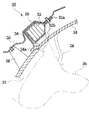
図4に図示されたように、ルーフサイドパネル(20a)の内側に設けられるサイドエアバッグ(10a)は前方部がフロントピラー(50a)にバックルで固定され、インフレータ(40a)が介在された後方部はリアピラー(70a)に連結されている。 As shown in FIG. 4, the side airbag (10a) provided inside the roof side panel (20a) has a front portion fixed to the front pillar (50a) with a buckle, and a rear side in which the inflator (40a) is interposed. The part is connected to the rear pillar (70a).
この時、センタピラー(60a)の上側のルーフサイドパネル(20a)には案内プレート(100)が設けられ、案内プレート(100)の拘束部材(120)と支持板(130)との間にサイドエアバッグハウジング(10b)が挟入される。 At this time, the guide plate (100) is provided on the roof side panel (20a) on the upper side of the center pillar (60a), and the side between the restraining member (120) of the guide plate (100) and the support plate (130). The airbag housing (10b) is inserted.
図示していないが、サイドエアバッグ(10a)には車両の衝突を感知するセンサと、センサの信号を受けてインフレータ(40a)を作動させる電子制御ユニットが内蔵されている。 Although not shown, the side airbag (10a) includes a sensor for detecting a collision of the vehicle and an electronic control unit for operating the inflator (40a) in response to a signal from the sensor.
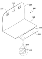
図5および図6には、本実施形態によるサイドエアバッグ用案内プレートおよびその設置構造が詳しく図示されている。 5 and 6 show the side airbag guide plate and its installation structure in detail according to the present embodiment.
図示されたように、本実施形態による案内プレート(100)は、ルーフサイドパネル(20a)とヘッドライナ(80a)との間に位置し、ルーフサイドパネル(20a)側に固定される。 As shown in the drawing, the guide plate (100) according to the present embodiment is positioned between the roof side panel (20a) and the head liner (80a), and is fixed to the roof side panel (20a) side.
案内プレート(100)は、固定部材(110)と固定部材(110)の下部に湾曲するように折曲されて車内側に延長される支持板(130)から構成され、固定部材(110)にある設置孔(111)を介してルーフサイドパネル(20a)にボルトで固定される。 The guide plate (100) includes a fixing member (110) and a support plate (130) that is bent so as to be bent at the lower portion of the fixing member (110) and is extended to the inside of the vehicle. It is fixed to the roof side panel (20a) with a bolt through a certain installation hole (111).
設置孔(111)の両側には固定突起(112)が形成されてルーフサイドパネル(20a)に形成された係止溝(図示しない)に係止されることで、ボルトと共に案内プレート(100)が回転しないように機能する。 Fixing protrusions (112) are formed on both sides of the installation hole (111) and locked in locking grooves (not shown) formed in the roof side panel (20a), so that the guide plate (100) together with the bolts. Functions to prevent rotation.
サイドエアバッグ(10a)は、拡張部(131)を含む支持板(130)と拘束部材(120)との間に固定されており、側面衝突時にサイドエアバッグ(10a)がヘッドライナ(80a)を開いて車内に展開される。 The side airbag (10a) is fixed between the support plate (130) including the expansion portion (131) and the restraining member (120), and the side airbag (10a) is the headliner (80a) at the time of a side collision. Will be opened in the car.
一方、図5に図示されたように、支持板(130)の端部には、下方へ折曲された誘導部(132)が形成されている。誘導部(132)によってサイドエアバッグ(10a)がルーフサイドパネル(20a)とヘッドライナ(80a)との間で下方に展開されることを防ぐ。 On the other hand, as shown in FIG. 5, a guide portion (132) bent downward is formed at the end of the support plate (130). The guide portion (132) prevents the side airbag (10a) from being deployed downward between the roof side panel (20a) and the headliner (80a).
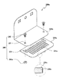
図6(a)に図示されたように、案内プレート(100)は、ルーフサイドパネル(20a)に固設される固定部材(110)、固定部材(110)の下部で緩やかな曲面に折曲される支持板(130)、固定部材(110)の上部から突出形成された拘束部材(120)から構成される。 As shown in FIG. 6 (a), the guide plate (100) is bent into a gently curved surface at the lower part of the fixing member (110) fixed to the roof side panel (20a) and the fixing member (110). The support plate (130) and the restraining member (120) formed to protrude from the upper part of the fixing member (110).
固定部材(110)には、ルーフサイドパネル(20a)への装着時にボルトが締結される設置孔(111)が形成され、設置孔(111)の両側には矩形孔と、矩形孔の一側に折曲される固定突起(112)が形成されている。 The fixing member (110) is provided with an installation hole (111) to which a bolt is fastened when mounted on the roof side panel (20a). A rectangular hole is formed on both sides of the installation hole (111) and one side of the rectangular hole. A fixed protrusion (112) that is bent to the right is formed.
また、設置孔(111)の下部には、固定部材(110)の表面から車内側に突出するように拘束部材(120)が形成される。拘束部材(120)は、サイドエアバッグ(10a)の展開時に上方に分散する力を拘束して下方に向かうようにすることで、ヘッドライナ(80a)が容易に開かれるようにする役割を果たす。 In addition, a restraining member (120) is formed below the installation hole (111) so as to protrude from the surface of the fixing member (110) to the vehicle interior side. The restraining member (120) plays a role of easily opening the headliner (80a) by restraining the force dispersed upward when the side airbag (10a) is deployed and heading downward. .
ここで、固定部材(110)の下端部には、曲面をなすように折曲された支持板(130)が連結形成されている。また、支持板(130)にはインフレータ(20a)の方向または両側に延長された拡張部(131)が形成されてエアバッグクッションをスムーズに展開させる(図6b、図6c参照)。 Here, a support plate (130) bent so as to form a curved surface is connected to the lower end portion of the fixing member (110). In addition, the support plate (130) is formed with an extended portion (131) extending in the direction of the inflator (20a) or on both sides to smoothly deploy the airbag cushion (see FIGS. 6b and 6c).
これによって、サイドエアバッグ(10a)を拘束するための別途の装置が不要となる。 This eliminates the need for a separate device for restraining the side airbag (10a).
一方、支持板(130)の端部には、誘導部(132)が略直角になるように折曲形成され、サイドエアバッグ(10a)の展開時にヘッドライナ(80a)を開き、車内に展開されるように誘導してセンタピラー(60a)の内側に展開されることを防ぐ。 On the other hand, at the end of the support plate (130), the guide portion (132) is bent so as to be substantially perpendicular, and the headliner (80a) is opened when the side airbag (10a) is deployed, and deployed in the vehicle. To prevent it from being deployed inside the center pillar (60a).
以下、図8を参照して本実施形態による案内プレートを含むサイドエアバッグの展開動作を説明する。 Hereinafter, the deployment operation of the side airbag including the guide plate according to the present embodiment will be described with reference to FIG.
まず、車両に衝撃が加えられ、この衝撃強度に応じたセンサの信号によってインフレータが作動し、エアバッグチューブの内部に膨脹ガスが注入されながら急速に膨脹する。 First, an impact is applied to the vehicle, the inflator is activated by a sensor signal corresponding to the impact strength, and the vehicle inflates rapidly while inflating gas is injected into the airbag tube.
この時、固定部材(110)の表面に突出形成された拘束部材(120)は、上方に展開されるサイドエアバッグを拘束して展開される力の分散を防ぎ、サイドエアバッグ(10a)がヘッドライナ(80a)を押して開くことで展開が容易になる。 At this time, the restraining member (120) formed to protrude from the surface of the fixing member (110) restrains the side airbag deployed upward to prevent the deployed force from being dispersed, and the side airbag (10a) Deployment is facilitated by pushing and opening the headliner (80a).
一方、センタピラー(60a)の近傍に案内プレート(100)が有する拡張部(131)によってサイドエアバッグ(10a)が車内側に展開されることで、センタピラー(60a)との干渉をなくすことができるので、スムーズな展開が行われる。 On the other hand, the side airbag (10a) is deployed on the vehicle interior side by the expansion portion (131) of the guide plate (100) in the vicinity of the center pillar (60a), thereby eliminating interference with the center pillar (60a). Can be deployed smoothly.
また、誘導部(132)は、サイドエアバッグ(10a)がセンタピラー(60a)の内部に展開されることを防ぎ、センタピラー(60a)の端部との干渉なしに車内にスムーズに展開されるように誘導する機能を果たす。 Further, the guide portion (132) prevents the side airbag (10a) from being deployed inside the center pillar (60a), and is smoothly deployed in the vehicle without interference with the end of the center pillar (60a). Fulfills the function of guiding.
<第2の実施形態>
図7(a)、図7(b)および図7(c)には、本発明の第2の実施形態による案内プレートの構成が図示されている。
<Second Embodiment>
7 (a), 7 (b) and 7 (c) show the structure of the guide plate according to the second embodiment of the present invention.
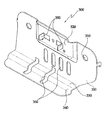
図7(a)に図示されたように、固定部材(110)の表面に突出形成された拘束部材(120)は、両側に延長形成された拘束延長部(121)をさらに含み、上方に加えられる力の分散をより容易に拘束する。 As shown in FIG. 7 (a), the restraining member (120) formed to protrude from the surface of the fixing member (110) further includes a restraining extension part (121) formed to extend on both sides. More easily restrains the distribution of the force being applied.
そして、図7(b)に図示されたように、固定部材(110)の下方にある支持板(130)の両側面に拡張部(131)を含み、サイドエアバッグ(10a)の展開時にセンタピラー(60a)によって干渉されないようにする。 As shown in FIG. 7 (b), the support plate (130) below the fixing member (110) includes expansion portions (131) on both side surfaces, and the side airbag (10a) is centered when the side airbag (10a) is deployed. Avoid interference by the pillar (60a).
また、図7(c)に図示されたように、拘束部材(120)の先端から下方に折曲された係止部(122)が形成されてサイドエアバッグ(10a)が固定されるようにし、サイドエアバッグ(10a)の展開時にヘッドライナ(80a)の方向に膨脹するように誘導する。 Further, as shown in FIG. 7C, a locking portion (122) bent downward from the tip of the restraining member (120) is formed to fix the side airbag (10a). When the side airbag (10a) is deployed, the side airbag (10a) is guided to inflate in the direction of the headliner (80a).
本実施形態による案内プレートを含むサイドエアバッグの展開動作は、第1の実施形態と同一であるため、重複する説明は省略する。 Since the deployment operation of the side airbag including the guide plate according to the present embodiment is the same as that of the first embodiment, a duplicate description is omitted.
<第3の実施形態>
以下、添付の図9〜図12を参照して本発明の第3の実施形態によるサイドエアバッグ用案内プレートを説明する。
<Third Embodiment>
Hereinafter, a side airbag guide plate according to a third embodiment of the present invention will be described with reference to FIGS.
図11に図示されたように、サイドエアバッグ(30)は、車両の内部側面に設けられて搭乗者を保護するためのものであり、内部に複数折り畳まれているエアバッグチューブ(36)、エアバッグチューブ(36)を内蔵するエアバッグハウジング(32)、エアバッグチューブ(36)の末端に連結されてエアバッグチューブ(36)に多量のガスを高圧噴射するインフレータ(20)から構成される。 As shown in FIG. 11, the side airbag (30) is provided on the inner side surface of the vehicle to protect the occupant, and an airbag tube (36) that is folded inside the vehicle. An airbag housing (32) containing an airbag tube (36), and an inflator (20) connected to the end of the airbag tube (36) to inject a large amount of gas into the airbag tube (36) at a high pressure. .
ここで、エアバッグハウジング(32)の一側にはドア(32b)が形成され、上端部にはボルトを介してインナーパネル(26)に固定されるマウンティング部(図示しない)が形成されている。そして、車内にはエアバッグハウジング(32)の所定の部位毎にエアバッグハウジング(32)の底面を支持する案内プレート(200)が設けられる(図12参照)。 Here, a door (32b) is formed on one side of the airbag housing (32), and a mounting portion (not shown) fixed to the inner panel (26) via a bolt is formed on the upper end. . A guide plate (200) that supports the bottom surface of the airbag housing (32) is provided for each predetermined portion of the airbag housing (32) in the vehicle (see FIG. 12).
図9および図12に図示されたように、サイドエアバッグ用案内プレート(200)は、サイドエアバッグ(30)のエアバッグハウジング(32)の底面を支持するものであって、エアバッグチューブ(36)の展開時に車内にスムーズに案内する役割を果たし、ボルトとナット(270、280)を介して車両のインナーパネル(26)に固定される固定部(210)、固定部(210)の下端部から折曲形成される支持部(220)から構成される。 9 and 12, the side airbag guide plate (200) supports the bottom surface of the airbag housing (32) of the side airbag (30). 36) which plays a role of guiding smoothly into the vehicle when deployed, and is fixed to the inner panel (26) of the vehicle via bolts and nuts (270, 280), the lower end of the fixed portion (210) It is comprised from the support part (220) bent-formed from a part.
固定部(210)は案内プレート(200)が動かないように固定するためのものであり、正面にはボルト(270)が挿入される挿入孔(211)が形成され、挿入孔(211)の両側面にはインナーパネル(26)に係止固定されるように“L”字状の係止片(212)が折曲形成され、下端部には支持部(220)が折曲形成されている。 The fixing part (210) is for fixing the guide plate (200) so that it does not move, and an insertion hole (211) into which a bolt (270) is inserted is formed on the front surface of the insertion hole (211). “L” -shaped locking pieces (212) are bent on both side surfaces so as to be locked and fixed to the inner panel (26), and support portions (220) are bent on the lower end. Yes.
具体的には、案内プレート(200)は、係止片(212)がインナーパネル(26)に形成された溝(図示しない)に係止されて動かなくされた状態で、挿入孔(211)にボルト(270)を通過させ、インナーパネル(26)の背面でナット(280)で係合することで、インナーパネル(25)に堅固に固定される。 Specifically, the guide plate (200) is inserted into the insertion hole (211) in a state where the locking piece (212) is locked in a groove (not shown) formed in the inner panel (26) and is not moved. The bolt (270) is passed through and engaged with the nut (280) on the back surface of the inner panel (26), thereby being firmly fixed to the inner panel (25).
支持部(220)は、固定部(210)の下端部から水平方向に折曲形成されてエアバッグハウジング(32)の底面を支持する。そして、支持部(220)の先端には補強支持部(230)が延長形成される。 The support part (220) is bent in the horizontal direction from the lower end part of the fixing part (210) and supports the bottom surface of the airbag housing (32). A reinforcing support part (230) is extended from the tip of the support part (220).
補強支持部(230)は、エアバッグハウジング(32)の内部に内蔵されたエアバッグチューブ(36)の展開時に、エアバッグハウジング(32)のドア(32b)の下側部を弾力的に支持するためのものであり、支持部(220)の先端部から外側方向に水平に延長形成される。 The reinforcing support portion (230) elastically supports the lower side portion of the door (32b) of the airbag housing (32) when the airbag tube (36) built in the airbag housing (32) is deployed. For this purpose, the support portion (220) is horizontally extended from the tip end portion in the outer direction.
図9および図10では、補強支持部(230)の幅が支持部(220)の幅よりも小さく形成されている。 In FIG. 9 and FIG. 10, the width of the reinforcing support part (230) is formed smaller than the width of the support part (220).
図11および図12に図示されたように、支持部(220)はエアバッグハウジング(32)の底面を支持し、補強支持部(230)はエアバッグチューブ(36)の展開時にエアバッグハウジング(32)のドア(32b)の下側部を支持する。 As shown in FIGS. 11 and 12, the support part (220) supports the bottom surface of the airbag housing (32), and the reinforcing support part (230) is used for the airbag housing (36) when the airbag tube (36) is deployed. 32) supports the lower side of the door (32b).
このように、補強支持部(230)によって案内プレート(200)をヘッドライナ(24)に近接するように配置することができるため、ヘッドライナ(24)とインナーパネル(26)との間の空間部を最小化させることができ、エアバッグチューブ(36)をより安定的に車内に展開させることができる。 In this way, the guide plate (200) can be disposed close to the headliner (24) by the reinforcing support (230), so that the space between the headliner (24) and the inner panel (26). Therefore, the airbag tube (36) can be more stably deployed in the vehicle.
ここで、補強支持部(230)の上面には、複数の孔(231、図10参照)が支持部(220)と補強支持部(230)の境界線方向に整列して形成されており、エアバッグチューブ(36)に高圧のガスが噴射された際に、エアバッグハウジング(32)のドア(32b)が瞬間的に折曲されてから復元する時の衝撃力を吸収することができる。 Here, a plurality of holes (231, see FIG. 10) are formed on the upper surface of the reinforcing support part (230) in alignment with the boundary line direction of the support part (220) and the reinforcing support part (230). When high pressure gas is injected into the airbag tube (36), it is possible to absorb an impact force when the door (32b) of the airbag housing (32) is instantaneously bent and then restored.
また、孔(231)は長孔からなることが好ましく、長孔は支持部(220)と補強支持部(230)の境界線に直交するように形成されることが好ましい。孔(231)を介して一つの部分に荷重が集中することを防ぐことができ、補助支持部(230)の破損を防ぐことができる。 Moreover, it is preferable that a hole (231) consists of a long hole, and it is preferable that a long hole is formed so as to be orthogonal to the boundary line of a support part (220) and a reinforcement support part (230). It is possible to prevent the load from being concentrated on one part through the hole (231), and to prevent the auxiliary support part (230) from being damaged.
一方、図10(b)および図10(c)に図示されたように、補強支持部(230)の上面または下面には、長手方向にノッチ部(232)が形成される。ノッチ部(232)は“半円”または “V”字状を有する。 On the other hand, as illustrated in FIGS. 10B and 10C, a notch portion (232) is formed in the longitudinal direction on the upper surface or the lower surface of the reinforcing support portion (230). The notch (232) has a “semicircle” or “V” shape.
これによって、エアバッグチューブ(36)に高圧のガスが噴射された際に、ノッチ部(232)によってエアバッグハウジング(32)のドア(32b)が瞬間的に折曲されてから復元する時の衝撃力を吸収することができる。 As a result, when high pressure gas is injected into the airbag tube (36), the door (32b) of the airbag housing (32) is momentarily bent by the notch portion (232) and then restored. Can absorb impact force.
<第4の実施形態>
図13に本発明の第4の実施形態によるサイドエアバッグ用案内プレートの構成が図示されている。以下、本実施形態を説明するにあたり、第3の実施形態と同一部分に対しては同一符号を付与し、重複する説明は省略する。
<Fourth Embodiment>
FIG. 13 shows the structure of a side airbag guide plate according to the fourth embodiment of the present invention. Hereinafter, in describing the present embodiment, the same parts as those in the third embodiment are denoted by the same reference numerals, and redundant descriptions are omitted.
図示されたように、案内プレート(200a)の支持部(220a)の先端部には、サイドエアバッグ(30)に内蔵されたエアバッグチューブ(36)の展開時に、エアバッグハウジング(32)の底面を弾力的に支持するように補強支持部(230a)が設けられている。 As shown in the drawing, at the distal end of the support portion (220a) of the guide plate (200a), when the airbag tube (36) built in the side airbag (30) is deployed, the airbag housing (32) A reinforcing support portion (230a) is provided so as to elastically support the bottom surface.
ここで、補強支持部(230a)は、ガイド手段(240)によってエアバッグの展開方向に移動が可能である。 Here, the reinforcing support part (230a) can be moved in the airbag deployment direction by the guide means (240).
具体的には、ガイド手段(240)は、支持部(220a)に形成される貫通孔(221)、補強支持部(230a)に貫通孔(221)に対応するように境界線に対して直交方向に延長形成される長孔(233)および長孔(233)と貫通孔(221)を貫通してナット(241a)で締結される係合ボルト(241)から構成される。 Specifically, the guide means (240) is orthogonal to the boundary line so as to correspond to the through hole (221) formed in the support portion (220a) and the through hole (221) in the reinforcing support portion (230a). It is comprised from the engagement bolt (241) penetrated by the long hole (233) extended in the direction, the long hole (233), and the through-hole (221), and fastened with a nut (241a).
これによって、係合ボルト(241)を緊締および解除することによって、補強支持部(230a)を長孔(233)に対して移動させることができ、補強支持部(230a)の突出長を調節することができる。 Accordingly, by tightening and releasing the engagement bolt (241), the reinforcing support part (230a) can be moved with respect to the long hole (233), and the protruding length of the reinforcing support part (230a) is adjusted. be able to.
ここで、エアバッグチューブ(36)の破損を防ぐために、補強支持部(230a)の表面には、合成樹脂または織物からなるコーティング層(250a)を形成することが好ましい。 Here, in order to prevent the airbag tube (36) from being damaged, it is preferable to form a coating layer (250a) made of synthetic resin or woven fabric on the surface of the reinforcing support portion (230a).
<第5の実施形態>
以下、添付の図14〜図16を参照して、本発明の第5の実施形態によるサイドエアバッグ用案内プレートの構成を説明する。
<Fifth Embodiment>
Hereinafter, the configuration of the side airbag guide plate according to the fifth embodiment of the present invention will be described with reference to FIGS.
サイドエアバッグ(30)は、内部に複数折り畳まれているエアバッグチューブ(36)、エアバッグチューブ(36)を内蔵するエアバッグハウジング(32)、エアバッグチューブ(36)の末端に連結されてエアバッグチューブ(36)に多量のガスを高圧噴射するインフレータ(20)から構成される。 The side airbag (30) is connected to the end of the airbag tube (36) folded inside, the airbag housing (32) containing the airbag tube (36), and the airbag tube (36). The inflator (20) is configured to inject a large amount of gas into the airbag tube (36) at a high pressure.
ここで、エアバッグハウジング(32)の一側にはドア(32b)が形成され、上端部にはボルトを介してインナーパネル(26)に固定されるマウンティング部(図示しない)が形成されている。そして、車内にはエアバッグハウジング(32)の所定の部位毎にエアバッグハウジング(32)の底面を支持する案内プレート(300)が設けられる(図15参照)。 Here, a door (32b) is formed on one side of the airbag housing (32), and a mounting portion (not shown) fixed to the inner panel (26) via a bolt is formed on the upper end. . A guide plate (300) that supports the bottom surface of the airbag housing (32) is provided for each predetermined portion of the airbag housing (32) in the vehicle (see FIG. 15).
案内プレート(300)は金属材からなり、固定片(390)によってインナーパネル(26)に固定される。 The guide plate (300) is made of a metal material and is fixed to the inner panel (26) by a fixing piece (390).
特に、固定片(390)の両側面には固定手段(301)、すなわちボルトを介してインナーパネル(26)に固定されるように挿入孔(310)が形成され、挿入孔(310)間の空間には、エアバッグハウジング(32)の一側面に密着支持されるように突出部(320)が形成され、下端部にはエアバッグハウジング(32)の底面を支持するように支持片(330)が折曲形成される。 In particular, insertion holes (310) are formed on both side surfaces of the fixing piece (390) so as to be fixed to the inner panel (26) through fixing means (301), that is, bolts, between the insertion holes (310). A protrusion (320) is formed in the space so as to be closely supported by one side of the airbag housing (32), and a support piece (330) is supported at the lower end to support the bottom surface of the airbag housing (32). ) Is bent.
ここで、支持片(330)の一側面には“L”字状の折曲部(340)が長手方向に形成されており、エアバッグチューブ(36)の膨脹時にエアバッグハウジング(32)のドア(32b)の下側が瞬間的に折曲されてから復原される時の衝撃力を吸収することができ、最終的に支持片(330)の破損および変形が発生することを防ぐ。 Here, an L-shaped bent portion (340) is formed in the longitudinal direction on one side surface of the support piece (330), and the airbag housing (32) is inflated when the airbag tube (36) is inflated. The impact force when the lower side of the door (32b) is instantaneously bent and then restored can be absorbed, and finally the breakage and deformation of the support piece (330) are prevented.
折曲部(340)は、センタピラートリム(22)の上端部よりも高い位置または上端部と同一の高さに位置することが好ましい。 The bent portion (340) is preferably located at a position higher than the upper end portion of the center pillar trim (22) or at the same height as the upper end portion.
これは、エアバッグチューブ(36)が、インナーパネル(26)とセンタピラートリム(22)との間に展開されることを防ぐためである。 This is to prevent the airbag tube (36) from being deployed between the inner panel (26) and the center pillar trim (22).
また、案内プレート(300)の表面には、複数の長孔(360)が形成されており、案内プレート(300)の重量減少およびコスト減少の効果を得ることができる。 Further, a plurality of long holes (360) are formed on the surface of the guide plate (300), and the effect of reducing the weight and cost of the guide plate (300) can be obtained.
同時に、案内プレート(300)の突出部(320)の表面には、エアバッグハウジング(32)を固定する固定板(304)が挟入されるように固定片(350)が突出して折曲形成される。 At the same time, the fixing piece (350) protrudes and bends on the surface of the protruding portion (320) of the guide plate (300) so that the fixing plate (304) for fixing the airbag housing (32) is inserted. Is done.
固定片(350)は、突出部(320)の表面にパンチを介して一側の垂直面を除いた3面をパンチングして折曲面を形成し、折曲面をエアバッグハウジング(32)の方向に90度折曲させて形成される。 The fixed piece (350) is punched on the surface of the projecting portion (320) via a punch to form a folded curved surface, and the folded curved surface is formed in the direction of the airbag housing (32). It is formed by bending 90 degrees.
固定片(350)は、エアバッグハウジング(32)を固定する固定板(304)に形成された溝に挿入された後、固定板(304)の溝を介して突出する固定片(350)を90度折曲させて固定する。 The fixing piece (350) is inserted into a groove formed in the fixing plate (304) for fixing the airbag housing (32), and then the fixing piece (350) protruding through the groove of the fixing plate (304) is inserted. Bend 90 degrees and fix.
サイドエアバッグ用案内プレートの組立方法および使用方法は、次のとおりである。 The method for assembling and using the side airbag guide plate is as follows.
まず、固定手段(301)を案内プレート(300)の挿入孔(310)に貫通させて案内プレート(300)をインナーパネル(26)に固定させる。 First, the fixing means (301) is passed through the insertion hole (310) of the guide plate (300) to fix the guide plate (300) to the inner panel (26).
次に、サイドエアバッグ(30)を介在させて案内プレート(300)の固定片(350)に固定板(304)の溝を挟んで固定させることで、サイドエアバッグ(30)を堅固に固定する。 Next, the side airbag (30) is firmly fixed by sandwiching the groove of the fixing plate (304) to the fixing piece (350) of the guide plate (300) with the side airbag (30) interposed therebetween. To do.
次に、車両の衝突時にインフレータ(20)によって多量のガスがエアバッグチューブ(36)の内部に高圧噴射されると、エアバッグチューブ(36)は膨脹しながらエアバッグハウジング(32)のドア(32b)を介して展開され、ヘッドライナ(24)を介して車内に展開される。 Next, when a large amount of gas is injected into the airbag tube (36) by the inflator (20) at the time of a vehicle collision, the airbag tube (36) is inflated while the door ( 32b) and in the vehicle via the headliner (24).
ここで、案内プレート(300)は、支持片(330)によってドア(32b)の下側部分が回転することを制限することで、エアバッグチューブ(36)がセンタピラートリム(22)とインナーパネル(26)との間に流入することを防ぐことができる。 Here, the guide plate (300) restricts the lower part of the door (32b) from being rotated by the support piece (330), so that the airbag tube (36) is connected to the center pillar trim (22) and the inner panel ( 26) can be prevented.
また、案内プレート(300)の折曲部(340)によって、エアバッグチューブ(36)に高圧のガスが噴射された場合、ドア(32b)の下側部分が瞬間的に折曲されてから復元する時の衝撃力を吸収することができるので、エアバッグチューブ(36)がより安定的に展開される。 Further, when high pressure gas is injected into the airbag tube (36) by the bent portion (340) of the guide plate (300), the lower portion of the door (32b) is instantaneously bent and then restored. Since the impact force can be absorbed, the airbag tube (36) is more stably deployed.
<第6の実施形態>
以下、図17を参照して本発明の第6の実施形態による案内プレートの構成を詳しく説明する。本実施形態は全体的に第5の実施形態と類似するので、異なる構成についてのみ記述する。
<Sixth Embodiment>
Hereinafter, the configuration of the guide plate according to the sixth embodiment of the present invention will be described in detail with reference to FIG. Since this embodiment is generally similar to the fifth embodiment, only different configurations will be described.
図示されたように、本実施形態による案内プレート(300)の折曲部(340a)は支持片(330a)の一側に傾斜した形状に折曲されている。 As illustrated, the bent portion (340a) of the guide plate (300) according to the present embodiment is bent into a shape inclined to one side of the support piece (330a).
従って、折曲部(340a)は、エアバッグハウジング(32)のドア(32b)の下側部分が折曲される時に支持することで、瞬間的に折曲されるドア(32b)の下側部分の変形または破損を防ぐことができる。 Accordingly, the bent portion (340a) is supported when the lower portion of the door (32b) of the airbag housing (32) is bent, so that the lower side of the door (32b) bent instantaneously. The deformation or breakage of the part can be prevented.
また、案内プレート(300)の表面には、コーティング層(370)が形成されることが好ましい。コーティング層(370)は、合成樹脂または織物を用いて案内プレート(300)の支持片(330a)および折曲部(340a)の表面を薄膜で覆うためのものであり、鋭利な部分によってエアバッグチューブ(36)が破れるなどの破損を防ぐことができる。 In addition, a coating layer (370) is preferably formed on the surface of the guide plate (300). The coating layer (370) is for covering the surfaces of the support piece (330a) and the bent portion (340a) of the guide plate (300) with a thin film using a synthetic resin or a woven fabric. Damage such as breaking of the tube (36) can be prevented.
前述のように本発明によれば、案内プレートによってサイドエアバッグクッションが上方に展開されることを拘束してサイドエアバッグクッションの展開時における力を分散させず、正常にヘッドライナを開いて展開させるように誘導することができる。 As described above, according to the present invention, the side airbag cushion is restrained from being deployed upward by the guide plate, and the force at the time of deployment of the side airbag cushion is not dispersed, and the headliner is normally opened and deployed. Can be induced.
また、本発明によれば、案内プレートの拡張部によってサイドエアバッグクッションの展開時にセンタピラーとの干渉がないように、予め方向を誘導してサイドエアバッグクッションをスムーズに展開することができる。 Further, according to the present invention, the side airbag cushion can be smoothly deployed by guiding the direction in advance so that the extension portion of the guide plate does not interfere with the center pillar when the side airbag cushion is deployed.
また、本発明によれば、案内プレートの誘導部によってサイドエアバッグを車内にスムーズに展開することができる。 Moreover, according to this invention, a side airbag can be smoothly expand | deployed in a vehicle by the guidance | induction part of a guide plate.
最終的に、本発明のかかる構成によって、サイドエアバッグの装着時に拘束するための別途の部品が不要となり、原価の節減および作業時間の短縮という効果が得られる。 Ultimately, such a configuration of the present invention eliminates the need for a separate part for restraining when the side airbag is mounted, thereby providing the effects of cost reduction and work time reduction.
また、本発明のサイドエアバッグ用案内プレートの支持部に補強支持部を延長形成すれば、エアバッグチューブの展開時において、エアバッグチューブをより安定的に車内に展開させることができる。 Further, if the reinforcing support portion is formed to extend to the support portion of the side airbag guide plate of the present invention, the airbag tube can be more stably deployed in the vehicle when the airbag tube is deployed.
また、補強支持部の上面に長手方向に複数の長孔を形成することで、エアバッグチューブに高圧のガスが噴射された場合、エアバッグハウジングのドアが瞬間的に折曲されてから復元する時の衝撃力を吸収することができる。 In addition, by forming a plurality of elongated holes in the longitudinal direction on the upper surface of the reinforcing support part, when high-pressure gas is injected into the airbag tube, the airbag housing door is instantaneously bent and then restored. Can absorb the impact force of time.
また、本発明によれば、補強支持部を支持部内で移動可能に固定することで、補強支持部の長さを調節することができ、車種およびサイドエアバッグの種類を問わずに適用が可能となる。 Further, according to the present invention, the length of the reinforcement support portion can be adjusted by fixing the reinforcement support portion so as to be movable within the support portion, and can be applied regardless of the type of vehicle and the side airbag. It becomes.
また、補強支持部の外周面にコーティング層を形成することで、エアバッグチューブの展開時にエアバッグチューブが破れるなどの破損を防ぐことができる。 Moreover, by forming the coating layer on the outer peripheral surface of the reinforcing support portion, it is possible to prevent damage such as the airbag tube from being broken when the airbag tube is deployed.
また、本発明によるサイドエアバッグ用案内プレートの支持片によってサイドエアバッグの底面を支持することで、エアバッグチューブの展開時にエアバッグチューブをより安定的に車内に流入させることができる。 In addition, by supporting the bottom surface of the side airbag with the support piece of the guide plate for the side airbag according to the present invention, the airbag tube can flow into the vehicle more stably when the airbag tube is deployed.
また、支持片に折曲部を形成することで、エアバッグチューブに高圧のガスが噴射された場合、エアバッグハウジングのドアが瞬間的に折曲されてから復元する時の衝撃力を吸収することができ、支持片が破損されることを効果的に防ぐことができる。 In addition, by forming a bent portion in the support piece, when high-pressure gas is injected into the airbag tube, the impact force when the airbag housing door is restored after being instantaneously bent is absorbed. It is possible to effectively prevent the support piece from being damaged.
また、本発明による案内プレートの表面に固定片を形成することで、サイドエアバッグを固定する固定板を別途の固定手段なしに簡便に固定することができる。 Further, by forming the fixing piece on the surface of the guide plate according to the present invention, the fixing plate for fixing the side airbag can be easily fixed without any additional fixing means.
また、本発明の案内プレートの表面に複数の長孔を形成することで、案内プレートの重量を著しく減少させることができ、製作コストを節減することができる。 Further, by forming a plurality of elongated holes on the surface of the guide plate of the present invention, the weight of the guide plate can be significantly reduced, and the manufacturing cost can be reduced.
以上、添付図面を参照しながら本発明の好適な実施形態について説明したが、本発明は係る例に限定されない。当業者であれば、特許請求の範囲に記載された技術的思想の範疇内において、各種の変更例または修正例に想到し得ることは明らかであり、それらについても当然に本発明の技術的範囲に属するものと了解される。 As mentioned above, although preferred embodiment of this invention was described referring an accompanying drawing, this invention is not limited to the example which concerns. It is obvious for those skilled in the art that various changes or modifications can be conceived within the scope of the technical idea described in the claims. It is understood that it belongs to.
10a サイドエアバッグ
20a ルーフサイドパネル
40a インフレータ
50a フロントピラー
60a センタピラー
70a リアピラー
80a ヘッドライナ
100 案内プレート
110 固定部材
111 設置孔
112 固定突起
120 拘束部材
130 支持板
131 拡張部
DESCRIPTION OF
Claims (4)
前記固定部材の下端部に折曲形成されて車内側に突出する支持板と、
前記支持板の上方で前記固定部材から車内側に突出する拘束部材とを含み、
上記支持板と上記拘束部材との間にその内部にエアバッグが収容されたエアバッグハウジングが挟まれるように構成され、
前記エアバッグハウジングの上面は前記拘束部材によって支持され、前記エアバッグハウジングの底面は前記支持板によって支持され、前記エアバッグハウジングの後面は前記固定部材の内面に接触支持されることにより、車内に向いた前記エアバッグハウジングの前面だけは支持されずに開放された状態で、前記エアバッグハウジングは支持されており、
前記支持板には、エアバッグが車内に展開されるように誘導するために、車内側の先端部に下方に折曲形成された誘導部が形成され、
前記支持板には、少なくとも一側面から突出するように拡張部が形成され、
前記支持板には、1つの設置孔、および前記設置孔の両側に位置する2つの固定突起が設けられており、前記固定突起が車体の内部側面に設けられた係止溝と係合することを特徴とする、サイドエアバッグ用案内プレート。 A fixing member fixed to the inner side surface of the vehicle body;
A support plate that is bent at the lower end of the fixing member and protrudes toward the vehicle interior;
A restraining member that protrudes inward from the fixing member above the support plate,
An airbag housing in which an airbag is housed is sandwiched between the support plate and the restraining member,
An upper surface of the airbag housing is supported by the restraining member, a bottom surface of the airbag housing is supported by the support plate, and a rear surface of the airbag housing is contacted and supported by an inner surface of the fixing member. The airbag housing is supported in a state where only the front surface of the airbag housing facing is opened without being supported,
In order to guide the airbag so that the airbag is deployed in the vehicle, a guide portion that is bent downward is formed at the front end portion of the vehicle inside ,
The support plate is formed with an extension so as to protrude from at least one side surface,
The support plate is provided with one installation hole and two fixing projections located on both sides of the installation hole, and the fixing projection engages with a locking groove provided on the inner side surface of the vehicle body. A side air bag guide plate.
Applications Claiming Priority (6)
| Application Number | Priority Date | Filing Date | Title |
|---|---|---|---|
| KR2020060008880U KR200418768Y1 (en) | 2006-04-04 | 2006-04-04 | guide plate for side air-bag |
| KR20-2006-0008880 | 2006-04-04 | ||
| KR2020060010396U KR200420468Y1 (en) | 2006-04-18 | 2006-04-18 | guide plate for side air-bag |
| KR20-2006-0010396 | 2006-04-18 | ||
| KR20-2006-0010487 | 2006-04-19 | ||
| KR2020060010487U KR200420470Y1 (en) | 2006-04-19 | 2006-04-19 | A guide plate for side airbag of vehicle |
Related Child Applications (1)
| Application Number | Title | Priority Date | Filing Date |
|---|---|---|---|
| JP2010040952A Division JP2010149857A (en) | 2006-04-04 | 2010-02-25 | Side airbag guide plate |
Publications (2)
| Publication Number | Publication Date |
|---|---|
| JP2007276767A JP2007276767A (en) | 2007-10-25 |
| JP4987540B2 true JP4987540B2 (en) | 2012-07-25 |
Family
ID=38226443
Family Applications (2)
| Application Number | Title | Priority Date | Filing Date |
|---|---|---|---|
| JP2007096728A Expired - Fee Related JP4987540B2 (en) | 2006-04-04 | 2007-04-02 | Side airbag guide plate |
| JP2010040952A Pending JP2010149857A (en) | 2006-04-04 | 2010-02-25 | Side airbag guide plate |
Family Applications After (1)
| Application Number | Title | Priority Date | Filing Date |
|---|---|---|---|
| JP2010040952A Pending JP2010149857A (en) | 2006-04-04 | 2010-02-25 | Side airbag guide plate |
Country Status (4)
| Country | Link |
|---|---|
| US (1) | US8141897B2 (en) |
| EP (2) | EP2363327B1 (en) |
| JP (2) | JP4987540B2 (en) |
| CN (1) | CN101712309B (en) |
Families Citing this family (16)
| Publication number | Priority date | Publication date | Assignee | Title |
|---|---|---|---|---|
| JP4987540B2 (en) * | 2006-04-04 | 2012-07-25 | オートリブ ディベロップメント エイビイ | Side airbag guide plate |
| JP5204993B2 (en) * | 2007-06-11 | 2013-06-05 | 本田技研工業株式会社 | Arrangement structure of interior parts of vehicle |
| JP2009262673A (en) * | 2008-04-23 | 2009-11-12 | Takata Corp | Bracket for curtain airbag and curtain airbag device |
| JP2009292441A (en) * | 2008-06-09 | 2009-12-17 | Takata Corp | Curtain airbag bracket and curtain airbag apparatus |
| KR101113672B1 (en) * | 2009-10-30 | 2012-02-17 | 아우토리브 디벨롭먼트 아베 | Ramp apparatus of curtain air bag for vehicle |
| JP5626121B2 (en) | 2011-05-26 | 2014-11-19 | 豊田合成株式会社 | Head protection airbag device |
| KR101292323B1 (en) | 2011-07-12 | 2013-07-31 | 아우토리브 디벨롭먼트 아베 | Side airbag module for vehicle seat |
| JP5639131B2 (en) * | 2012-09-07 | 2014-12-10 | 富士重工業株式会社 | Arrangement structure of curtain airbag device |
| US9174602B1 (en) * | 2014-11-12 | 2015-11-03 | Toyota Motor Engineering & Manufacturing North America, Inc. | Side pillar assemblies with multi-surface retention structures for side airbags |
| DE102015006898A1 (en) * | 2015-06-03 | 2016-12-22 | Trw Airbag Systems Gmbh | An assembly of a vehicle safety system, vehicle safety system, vehicle safety device, and method for manufacturing an assembly of a vehicle safety system |
| US9573550B1 (en) * | 2015-08-17 | 2017-02-21 | Autoliv Asp, Inc. | Side curtain airbag compression inflator bracket |
| US9643561B2 (en) * | 2015-09-16 | 2017-05-09 | Ford Global Technologies, Llc | Overhead side air curtain protective barrier |
| JP6717177B2 (en) * | 2016-12-07 | 2020-07-01 | トヨタ自動車株式会社 | Curtain airbag system for vehicles |
| KR102647194B1 (en) * | 2018-11-16 | 2024-03-13 | 현대자동차주식회사 | Curtain airbag for vehicle |
| US11865990B2 (en) * | 2022-05-25 | 2024-01-09 | Autoliv Asp, Inc. | Ramp bracket for a curtain airbag |
| US11904791B1 (en) * | 2022-12-29 | 2024-02-20 | Rivian Ip Holdings, Llc | Fabric molded roof rail airbag shell |
Family Cites Families (44)
| Publication number | Priority date | Publication date | Assignee | Title |
|---|---|---|---|---|
| JP3120726B2 (en) * | 1995-12-14 | 2000-12-25 | トヨタ自動車株式会社 | Seat structure with side collision airbag |
| KR100282950B1 (en) * | 1996-11-07 | 2001-04-02 | 와다 아끼히로 | Structure of arrangement of passenger protective devices for cars |
| US5762363A (en) * | 1997-01-21 | 1998-06-09 | Ford Global Technologies, Inc. | Seamless side inflatable restraint deployment system |
| JP3125729B2 (en) * | 1997-09-26 | 2001-01-22 | トヨタ自動車株式会社 | Arrangement structure of head protection airbag bag |
| JP3093199B2 (en) * | 1998-05-12 | 2000-10-03 | トヨタ自動車株式会社 | Arrangement structure of head protection airbag device |
| US6371512B1 (en) * | 1998-08-03 | 2002-04-16 | Toyota Jidosha Kabushiki Kaisha | Airbag apparatus for head-protecting |
| JP3481473B2 (en) * | 1998-10-01 | 2003-12-22 | トヨタ自動車株式会社 | Arrangement structure of head protection airbag bag |
| US6254123B1 (en) * | 1998-08-03 | 2001-07-03 | Toyota Jidosha Kabushiki Kaisha | Mounting structure for use with a head-protecting airbag body |
| JP3702663B2 (en) * | 1998-09-01 | 2005-10-05 | タカタ株式会社 | Installation structure for passenger head protection bag |
| JP2001122073A (en) * | 1999-10-25 | 2001-05-08 | Toyota Motor Corp | Pillar garnish fitting structure in vehicle equipped with head protective air bag |
| JP2001163160A (en) * | 1999-12-08 | 2001-06-19 | Daihatsu Motor Co Ltd | Air bag device |
| EP2186689B1 (en) * | 1999-12-27 | 2016-11-30 | Toyoda Gosei Co., Ltd. | Head protecting air bag apparatus |
| JP4278261B2 (en) * | 2000-02-10 | 2009-06-10 | 株式会社イノアックコーポレーション | Quarter window garnish structure for vehicles with curtain airbags |
| JP4534368B2 (en) * | 2001-02-26 | 2010-09-01 | 豊田合成株式会社 | Head protection airbag device |
| JP3893887B2 (en) * | 2001-03-14 | 2007-03-14 | マツダ株式会社 | Vehicle occupant protection device |
| DE10225677A1 (en) * | 2001-06-11 | 2003-01-16 | Honda Motor Co Ltd | Occupant restraint system for motor vehicle, has airbag with gas pipe support formed from portion of stitching defining multiple cells |
| DE10137634A1 (en) * | 2001-08-03 | 2003-02-20 | Daimler Chrysler Ag | Airbag safety system for vehicle seats has airbag module mounted behind backrest frame and set in housing which surrounds rear facing area and side areas |
| DE20118457U1 (en) * | 2001-11-14 | 2002-04-04 | Trw Repa Gmbh | Side airbag module for a vehicle occupant protection system |
| US6923286B2 (en) * | 2002-02-26 | 2005-08-02 | Toyoda Gosei Co., Ltd. | Pedestrian protecting device |
| JP3741061B2 (en) * | 2002-02-27 | 2006-02-01 | 日産自動車株式会社 | Shock absorption structure at the top of the car body |
| JP3935032B2 (en) * | 2002-09-06 | 2007-06-20 | 本田技研工業株式会社 | Crew restraint system |
| JP4490031B2 (en) * | 2002-09-26 | 2010-06-23 | 日本プラスト株式会社 | Airbag |
| KR100471328B1 (en) * | 2002-11-15 | 2005-03-08 | 기아자동차주식회사 | Automobile Pillar Air Bag Device |
| DE20300254U1 (en) * | 2003-01-09 | 2003-05-15 | Trw Repa Gmbh | Fastening device for tubular gas generator of side airbag module has support section into which is integrated deployment ramp |
| ITTO20030066U1 (en) * | 2003-04-09 | 2004-10-10 | Fiat Auto Spa | REINFORCEMENT CENTINA FOR THE ROOF OF A VEHICLE WITH INTEGRATED HE AD-BAG DIVERTER. |
| JP4449452B2 (en) * | 2003-05-30 | 2010-04-14 | タカタ株式会社 | Crew protection device |
| KR100535049B1 (en) * | 2003-10-24 | 2005-12-07 | 기아자동차주식회사 | mounting structure of trim for receiving curtain airbag |
| US7175196B2 (en) * | 2004-02-09 | 2007-02-13 | Trw Vehicle Safety Systems Inc. | Support bracket for an inflatable curtain |
| JP2005219426A (en) | 2004-02-09 | 2005-08-18 | Ricoh Co Ltd | Liquid discharge head, liquid cartridge, liquid discharge device, image forming device and liquid discharge head manufacturing method |
| US7097200B2 (en) * | 2004-04-12 | 2006-08-29 | Autoliv Asp, Inc. | Inflatable curtain trajectory bracket |
| DE102004028513A1 (en) * | 2004-06-11 | 2005-12-29 | Volkswagen Ag | Safety installation for a motor vehicle has airbag folded in inactive state in fastening area and unfolded in inflation area, with deformable airbag guide ramp which emerges from airbag inflation area with airbag in a crash |
| KR100599691B1 (en) | 2004-07-28 | 2006-07-13 | 삼성에스디아이 주식회사 | Secondary battery and electrodes assembly |
| KR100587106B1 (en) | 2004-07-28 | 2006-06-08 | 대우전자부품(주) | Ultrahigh voltage electrolyte of aluminium electrolytic condenser |
| US7182366B2 (en) * | 2004-08-27 | 2007-02-27 | Trw Vehicle Safety Systems Inc. | Inflatable curtain deployment ramp |
| JP4343062B2 (en) * | 2004-08-31 | 2009-10-14 | 本田技研工業株式会社 | Curtain airbag device |
| JP4487704B2 (en) * | 2004-09-21 | 2010-06-23 | 三菱自動車工業株式会社 | Vehicle side door |
| US7401805B2 (en) * | 2004-12-06 | 2008-07-22 | Key Safety Systems, Inc | Curtain air bag module |
| EP1721788B1 (en) * | 2005-04-22 | 2011-08-24 | Lisi Automotive Rapid | Fastening element for fastening and restraining an airbag on a vehicle body |
| JP4736665B2 (en) * | 2005-09-20 | 2011-07-27 | タカタ株式会社 | Curtain airbag mounting bracket and mounting structure, and curtain airbag device |
| JP4342501B2 (en) * | 2005-10-18 | 2009-10-14 | トヨタ自動車株式会社 | Airbag device |
| KR100757153B1 (en) * | 2005-12-12 | 2007-09-07 | 현대자동차주식회사 | The Pillar Ramp Structure Which Prevents a Curtain Air-Bag The Interference |
| JP4907184B2 (en) * | 2006-02-02 | 2012-03-28 | タカタ株式会社 | Airbag device |
| JP4987540B2 (en) * | 2006-04-04 | 2012-07-25 | オートリブ ディベロップメント エイビイ | Side airbag guide plate |
| US20070241542A1 (en) * | 2006-04-18 | 2007-10-18 | Mark Wallace | Air Bag Deployment Ramp |
-
2007
- 2007-04-02 JP JP2007096728A patent/JP4987540B2/en not_active Expired - Fee Related
- 2007-04-02 EP EP11001522A patent/EP2363327B1/en not_active Expired - Fee Related
- 2007-04-02 EP EP07006826A patent/EP1842741B1/en not_active Expired - Fee Related
- 2007-04-03 US US11/732,488 patent/US8141897B2/en not_active Expired - Fee Related
- 2007-04-04 CN CN2009102227606A patent/CN101712309B/en not_active Expired - Fee Related
-
2010
- 2010-02-25 JP JP2010040952A patent/JP2010149857A/en active Pending
Also Published As
| Publication number | Publication date |
|---|---|
| US20070241543A1 (en) | 2007-10-18 |
| CN101712309A (en) | 2010-05-26 |
| US8141897B2 (en) | 2012-03-27 |
| EP1842741B1 (en) | 2013-01-23 |
| EP2363327B1 (en) | 2012-12-05 |
| JP2010149857A (en) | 2010-07-08 |
| JP2007276767A (en) | 2007-10-25 |
| EP1842741A2 (en) | 2007-10-10 |
| EP1842741A3 (en) | 2009-06-03 |
| CN101712309B (en) | 2012-09-05 |
| EP2363327A1 (en) | 2011-09-07 |
Similar Documents
| Publication | Publication Date | Title |
|---|---|---|
| JP4987540B2 (en) | Side airbag guide plate | |
| JP5230514B2 (en) | Side airbag guide plate for vehicles | |
| EP2988975B1 (en) | Top tether for curtain airbag | |
| US7735855B2 (en) | Bracket for securing side airbag for automotive vehicle | |
| US8894094B2 (en) | Curtain airbag for small overlap | |
| US9266494B2 (en) | Fold over design for small overlap | |
| JP6294952B2 (en) | Double-folded cushion for IC | |
| JPH10138858A (en) | Arrangement structure for occupant protection device for automobile | |
| JP2008137629A (en) | Curtain airbag for vehicle | |
| JP2010235043A (en) | Airbag device | |
| KR200418768Y1 (en) | guide plate for side air-bag | |
| KR100947997B1 (en) | Folding Method For Air Bag | |
| KR100640008B1 (en) | Side air-bag for vehicles | |
| KR200418224Y1 (en) | A clip for side airbag of vehicle | |
| KR100776020B1 (en) | A guide plate for side airbag of vehicle | |
| KR101003899B1 (en) | Curtain air-bag module | |
| KR100745636B1 (en) | A holder for side airbag of vehicle | |
| KR200420470Y1 (en) | A guide plate for side airbag of vehicle | |
| CN218777492U (en) | Roof airbag for vehicle | |
| KR200420465Y1 (en) | A guide plate for side airbag of vehicle | |
| KR100787672B1 (en) | The vehicle of curtain air bag | |
| KR100776013B1 (en) | Guide Plate for Side Air-bag | |
| KR200420468Y1 (en) | guide plate for side air-bag | |
| KR200420483Y1 (en) | A bracket for side airbag of vehicle | |
| KR200420466Y1 (en) | A holder for side airbag of vehicle |
Legal Events
| Date | Code | Title | Description |
|---|---|---|---|
| RD02 | Notification of acceptance of power of attorney |
Free format text: JAPANESE INTERMEDIATE CODE: A7422 Effective date: 20080416 |
|
| RD04 | Notification of resignation of power of attorney |
Free format text: JAPANESE INTERMEDIATE CODE: A7424 Effective date: 20080509 |
|
| A131 | Notification of reasons for refusal |
Free format text: JAPANESE INTERMEDIATE CODE: A131 Effective date: 20090825 |
|
| A601 | Written request for extension of time |
Free format text: JAPANESE INTERMEDIATE CODE: A601 Effective date: 20091124 |
|
| A602 | Written permission of extension of time |
Free format text: JAPANESE INTERMEDIATE CODE: A602 Effective date: 20091127 |
|
| A601 | Written request for extension of time |
Free format text: JAPANESE INTERMEDIATE CODE: A601 Effective date: 20091225 |
|
| A602 | Written permission of extension of time |
Free format text: JAPANESE INTERMEDIATE CODE: A602 Effective date: 20100105 |
|
| A601 | Written request for extension of time |
Free format text: JAPANESE INTERMEDIATE CODE: A601 Effective date: 20100125 |
|
| A602 | Written permission of extension of time |
Free format text: JAPANESE INTERMEDIATE CODE: A602 Effective date: 20100128 |
|
| A521 | Request for written amendment filed |
Free format text: JAPANESE INTERMEDIATE CODE: A523 Effective date: 20100225 |
|
| RD02 | Notification of acceptance of power of attorney |
Free format text: JAPANESE INTERMEDIATE CODE: A7422 Effective date: 20100406 |
|
| A02 | Decision of refusal |
Free format text: JAPANESE INTERMEDIATE CODE: A02 Effective date: 20100622 |
|
| A521 | Request for written amendment filed |
Free format text: JAPANESE INTERMEDIATE CODE: A523 Effective date: 20101008 |
|
| A911 | Transfer to examiner for re-examination before appeal (zenchi) |
Free format text: JAPANESE INTERMEDIATE CODE: A911 Effective date: 20101026 |
|
| A711 | Notification of change in applicant |
Free format text: JAPANESE INTERMEDIATE CODE: A711 Effective date: 20101112 |
|
| A912 | Re-examination (zenchi) completed and case transferred to appeal board |
Free format text: JAPANESE INTERMEDIATE CODE: A912 Effective date: 20110114 |
|
| A601 | Written request for extension of time |
Free format text: JAPANESE INTERMEDIATE CODE: A601 Effective date: 20111107 |
|
| A521 | Request for written amendment filed |
Free format text: JAPANESE INTERMEDIATE CODE: A523 Effective date: 20111109 |
|
| A602 | Written permission of extension of time |
Free format text: JAPANESE INTERMEDIATE CODE: A602 Effective date: 20111114 |
|
| A01 | Written decision to grant a patent or to grant a registration (utility model) |
Free format text: JAPANESE INTERMEDIATE CODE: A01 |
|
| A61 | First payment of annual fees (during grant procedure) |
Free format text: JAPANESE INTERMEDIATE CODE: A61 Effective date: 20120425 |
|
| R150 | Certificate of patent or registration of utility model |
Free format text: JAPANESE INTERMEDIATE CODE: R150 |
|
| FPAY | Renewal fee payment (event date is renewal date of database) |
Free format text: PAYMENT UNTIL: 20150511 Year of fee payment: 3 |
|
| R250 | Receipt of annual fees |
Free format text: JAPANESE INTERMEDIATE CODE: R250 |
|
| R250 | Receipt of annual fees |
Free format text: JAPANESE INTERMEDIATE CODE: R250 |
|
| R250 | Receipt of annual fees |
Free format text: JAPANESE INTERMEDIATE CODE: R250 |
|
| LAPS | Cancellation because of no payment of annual fees |