JP4975523B2 - Component built-in board - Google Patents
Component built-in board Download PDFInfo
- Publication number
- JP4975523B2 JP4975523B2 JP2007140141A JP2007140141A JP4975523B2 JP 4975523 B2 JP4975523 B2 JP 4975523B2 JP 2007140141 A JP2007140141 A JP 2007140141A JP 2007140141 A JP2007140141 A JP 2007140141A JP 4975523 B2 JP4975523 B2 JP 4975523B2
- Authority
- JP
- Japan
- Prior art keywords
- substrate
- electronic component
- imaging device
- component
- wiring
- Prior art date
- Legal status (The legal status is an assumption and is not a legal conclusion. Google has not performed a legal analysis and makes no representation as to the accuracy of the status listed.)
- Active
Links
Images


Classifications
-
- H—ELECTRICITY
- H01—ELECTRIC ELEMENTS
- H01L—SEMICONDUCTOR DEVICES NOT COVERED BY CLASS H10
- H01L2224/00—Indexing scheme for arrangements for connecting or disconnecting semiconductor or solid-state bodies and methods related thereto as covered by H01L24/00
- H01L2224/01—Means for bonding being attached to, or being formed on, the surface to be connected, e.g. chip-to-package, die-attach, "first-level" interconnects; Manufacturing methods related thereto
- H01L2224/10—Bump connectors; Manufacturing methods related thereto
- H01L2224/15—Structure, shape, material or disposition of the bump connectors after the connecting process
- H01L2224/16—Structure, shape, material or disposition of the bump connectors after the connecting process of an individual bump connector
Landscapes
- Structures For Mounting Electric Components On Printed Circuit Boards (AREA)
- Combinations Of Printed Boards (AREA)
- Solid State Image Pick-Up Elements (AREA)
- Studio Devices (AREA)
Description
本発明は部品内蔵基板に係り、特に撮像処理を行う電子部品が組み込まれる部品内蔵基板に関する。 The present invention relates to a component-embedded substrate, and more particularly to a component-embedded substrate in which an electronic component that performs imaging processing is incorporated.
近年、小型カメラを内蔵した携帯電話機が広く利用されるようになってきており、これに伴い固体撮像素子等の撮像処理を行う電子部品(以下、撮像デバイスという)を携帯電話機の基板に搭載することが行われるようになってきている。また、携帯電話機では携帯性が要求されており、従って内設される電子部品も小型化及び薄型化が要求されている。 In recent years, mobile phones with built-in small cameras have been widely used, and accordingly, electronic components (hereinafter referred to as imaging devices) that perform imaging processing such as solid-state imaging devices are mounted on the substrates of mobile phones. Things are starting to happen. In addition, the mobile phone is required to have portability, and accordingly, the electronic components provided therein are also required to be reduced in size and thickness.
また撮像デバイスを基板に搭載する場合、一般に撮像デバイスの駆動制御を行うデジタルシグナルプロセッサ(DSP)も合わせて基板に搭載することが行われる。更に、撮像デバイスの上部には、撮像品質の向上の面から撮像領域に塵埃が付着するのを防止するガラス板(透明な保護部材)が設けられる。 When an imaging device is mounted on a substrate, generally a digital signal processor (DSP) that performs drive control of the imaging device is also mounted on the substrate. Furthermore, a glass plate (transparent protective member) that prevents dust from adhering to the imaging region is provided on the upper part of the imaging device in terms of improving imaging quality.
従来では、配線基板にDSP及び撮像デバイスを配設する際、単に配線基板にDSP、撮像デバイス、及びガラス板を積層することにより小型化が図られていた。(例えば、特許文献1参照)。
しかしながら従来の構成では、配線基板の上部にDSP、撮像デバイス、及びガラス板が積層されるため、その高さが高くなり携帯電話機等の電子機器の薄型化を妨げる原因となるという問題点があった。 However, in the conventional configuration, since the DSP, the imaging device, and the glass plate are laminated on the upper part of the wiring board, there is a problem in that the height of the circuit board becomes high, which prevents the electronic devices such as mobile phones from being thinned. It was.
本発明は上記の点に鑑みてなされたものであり、撮像処理を行う電子部品を設けても小型化を図りうる部品内蔵基板を提供することを目的とする。 The present invention has been made in view of the above points, and an object of the present invention is to provide a component-embedded substrate that can be reduced in size even when an electronic component that performs imaging processing is provided.
上記の課題は、本発明の第1の観点からは、
第1の電子部品と、
その一面側に撮像領域を有する撮像素子である第2の電子部品と、
第1の配線が形成されると共に前記第1の電子部品の一面側が搭載される第1の基板と、
第2の配線が形成されると共に前記第1の基板に積層される第2の基板と、
前記第1の基板と前記第2の基板を電気的に接続する接続部材と、
前記第1の基板と前記第2の基板の間に前記第1の電子部品を封止するよう配設される封止樹脂とを有し、
前記第2の電子部品に、該第2の電子部品の一面側を保護する透明部材を設け、
前記第2の電子部品を、前記第2の基板の前記接続部材が接続されている面に配設し、
前記第2の基板に開口部を形成すると共に、前記第2の電子部品の一面側が該開口部と対向するよう配設し、
前記透明部材は、前記開口部の少なくとも一部の領域に位置している部品内蔵基板により解決することができる。
From the first aspect of the present invention, the above problem is
A first electronic component;
A second electronic component that is an imaging device having an imaging region on one side thereof ;
A first substrate on which a first wiring is formed and one surface side of the first electronic component is mounted;
A second substrate on which a second wiring is formed and stacked on the first substrate;
A connection member for electrically connecting the first substrate and the second substrate;
A sealing resin disposed between the first substrate and the second substrate to seal the first electronic component;
A transparent member that protects one surface side of the second electronic component is provided on the second electronic component,
Disposing the second electronic component on a surface of the second substrate to which the connection member is connected;
An opening is formed in the second substrate, and one surface side of the second electronic component is disposed so as to face the opening.
The transparent member can be solved by a component-embedded substrate located in at least a partial region of the opening .
また、上記発明において、前記第2の電子部品の他面側と、前記第1の電子部品の他面側とが互いに対向するよう配置した構成としてもよい。 Moreover, in the said invention, it is good also as a structure arrange | positioned so that the other surface side of a said 2nd electronic component and the other surface side of a said 1st electronic component may mutually oppose.
また、上記発明において、前記第2の基板に、前記第2の電子部品と対向するレンズが配設されたレンズユニットを設けた構成としてもよい。
また上記の課題は、本発明の第2の観点からは、
第1の電子部品と、
その一面側に撮像領域を有する撮像素子である第2の電子部品と、
第1の配線が形成されると共に前記第1の電子部品の一面側が搭載される第1の基板と、
第2の配線が形成されると共に前記第1の基板に積層される第2の基板と、
前記第1の基板と前記第2の基板を電気的に接続する接続部材と、
前記第1の基板と前記第2の基板の間に前記第1の電子部品を封止するよう配設される封止樹脂とを有し、
前記第2の基板に開口部を形成すると共に、前記第2の電子部品の一面側が該開口部と対向し、
前記第2の電子部品の少なくとも一部が前記開口部の領域に位置するように設け、
前記第2の電子部品が、前記第2の基板とワイヤボンディングにより接続された部品内蔵基板により解決することができる。
また、上記発明において、前記第2の基板に、前記第2の電子部品と対向するレンズが配設されたレンズユニットを設けた構成としてもよい。
In the above invention, a lens unit in which a lens facing the second electronic component is provided on the second substrate may be provided.
In addition, the above-mentioned problem is from the second viewpoint of the present invention.
A first electronic component;
A second electronic component that is an imaging device having an imaging region on one side thereof ;
A first substrate on which a first wiring is formed and one surface side of the first electronic component is mounted;
A second substrate on which a second wiring is formed and stacked on the first substrate;
A connection member for electrically connecting the first substrate and the second substrate;
A sealing resin disposed between the first substrate and the second substrate to seal the first electronic component;
An opening is formed in the second substrate, and one surface side of the second electronic component is opposed to the opening ,
Providing at least a part of the second electronic component so as to be located in a region of the opening;
The second electronic component can be solved by a component built-in substrate connected to the second substrate by wire bonding.
In the above invention, a lens unit in which a lens facing the second electronic component is provided on the second substrate may be provided.
本発明によれば、第2の電子部品の回路面が、第2の基板に形成された開口部と対向するよう配設したことにより、第1の電子部品と共に第2の電子部品を第1及び第2の基板内に内蔵することができ、電子部品を回路基板の上部に積層して配設していた従来構成に比べ、第2の電子部品を含めた部品内蔵基板の薄型化、小型化を図ることができる。 According to the present invention, the second electronic component is arranged together with the first electronic component by arranging the circuit surface of the second electronic component so as to face the opening formed in the second substrate. Compared to the conventional configuration in which the electronic component can be built in the second substrate and stacked on the circuit board, the component built-in substrate including the second electronic component is made thinner and smaller. Can be achieved.
次に、本発明を実施するための最良の形態について図面と共に説明する。 Next, the best mode for carrying out the present invention will be described with reference to the drawings.
図1は、本発明の第1実施例である部品内蔵基板10Aを示している。尚、以下の説明においては、図1に矢印Z1で示す側を上方とし、矢印Z2で示す側を下方とする。また、図2以降の各図においても同様とする。
FIG. 1 shows a component built-in
部品内蔵基板10Aは、大略すると第1の基板100,第2の基板200,半導体チップ110A(請求項に記載の第1の電子部品に相当する),撮像デバイス110B(請求項に記載の第2の電子部品に相当する),電極112,封止樹脂115,及びガラス板130(請求項に記載の透明部材に相当する)等により構成されている。
The component-embedded
第1の基板100は、コア基板101、ビルドアップ層101A,101B、配線パターン103A,103B、内層配線103C、及びソルダーレジスト層104A,104B等により構成されている。
The
コア基板101は、プリプレグ材(ガラス繊維にエポキシ樹脂などを含浸させた材料)よりなり、その両面には例えばCuよりなる内層配線103Cが形成されている。また、コア基板101の両面に形成された内層配線103Cは、コア基板101を貫通して形成されたビアプラグ102により電気的に接続されている。
The
このコア基板101の図中上面にはビルドアップ層101Aが形成され、また下面にはビルドアップ層101Bが形成される。このビルドアップ層101Aの上面には例えばCuからなる配線パターン103Aが形成されると共に、ビルドアップ層101Bの下面には例えばCuからなる配線パターン103Bが形成されている。配線パターン103Aは、層間ビア105Aを介して内層配線103Cに接続され、配線パターン103Bは層間ビア105Bを介して内層配線103Cに接続されている。
A
また、ビルドアップ層101Aの図中上面には、ソルダーレジスト層104Aが形成されている。このソルダーレジスト層104Aは、後述する半導体チップ110Aの接合位置、及び電極112の接合位置が除去されて接続孔117A(図3(A)参照)が形成されている。配線パターン103Aは、この接続孔117Aから露出した状態となっている。
A
また、ビルドアップ層101Bの図中下面には、ソルダーレジスト層104Bが形成されている。このソルダーレジスト層104Bは、後述するはんだボール111が接続される位置に接続孔117Bが形成されている。配線パターン103Bは、この接続孔117Bから露出した状態となっている。
Further, a
この接続孔117A,117Bから露出した配線パターン103A,103Bの内、後述する電極112或いははんだボール111がはんだ接合される位置には、はんだ付け性を高めるために例えばNi/Au(配線パターン103A上にNi層、Au層の順に積層された層)等よりなる接続層が形成されている(接続層の図示は省略している)。また、接続孔117A,117Bから露出した配線パターン103A,103Bの内、半導体チップ110Aがフリップチップ接合される位置には、例えばはんだ等よりなる接続層107が印刷法、電解メッキ法等により形成されている。
Of the
半導体チップ110Aは、後述する撮像デバイス110Bの制御を行うデジタルシグナルプロセッサ(DSP)である。この半導体チップ110Aは、フリップチップ接合により第1の基板100に搭載される。
The
具体的には、半導体チップ110Aの主面にはバンプ108が形成されており、このバンプ108を前記した接続層107に接合することにより、半導体チップ110Aは第1の基板100にフリップチップ接合される。また、半導体チップ110Aと第1の基板100の上面100aとの間には、接合信頼性を高めるためにアンダーフィル樹脂109が配設される。
Specifically,
尚、本実施例では半導体チップ110AとしてDSPを用いた例を示しているが他のチップ状の部品(例えば、キャパシタ、レジスタ、インダクタ等)を用いることが可能である。
In the present embodiment, an example is shown in which a DSP is used as the
はんだボール111は外部接続端子として機能するものであり、第1の基板100の下面100bに配設されている。具体的には、前記のようにソルダーレジスト層104Bには配線パターン103Bが露出した接続孔117Bが形成されており、はんだボール111はこの接続孔117Bから露出した配線パターン103Bに接合されている。
The
一方、第2の基板200は、コア基板201、配線パターン203A,203B、及びソルダーレジスト層204等により構成されている。
On the other hand, the
コア基板201は、前記した第1の基板100のコア基板101と同様に、プリプレグ材よりなり、その上面には例えばCuよりなる配線パターン203Aが形成され、また下面には電極112又は撮像デバイス110Bが接合される配線パターン203Bが形成されている。
Similarly to the
この配線パターン203A,203Bは、コア基板201を貫通して形成されたビアプラグ202により電気的に接続されている。また、配線パターン203Aが形成されたコア基板201の図中上面にはソルダーレジスト層204Aが形成されると共に、配線パターン203Bが形成されたコア基板201の図中下面にはソルダーレジスト層204Bが形成されている。
The
一方、第2の基板200の略中央位置には、開口部206が形成されている。この開口部206は第2の基板200を貫通して形成されており、またその形状は後述する撮像デバイス110B及びガラス板130の形状に対応するよう設定されている。
On the other hand, an
撮像デバイス110Bは、第2の基板200の下面200bで開口部206が形成された位置に配設されている。この撮像デバイス110Bは、例えば固体撮像素子(CCD)であり、素子の回路面(能動面)に形成された撮像領域129を囲繞する外周にはバンプ135が形成されている。
The imaging device 110 </ b> B is disposed at a position where the
また本実施例では、撮像デバイス110Bの撮像領域129の上部にはガラス板130が接合剤133を用いて接合されている。接合剤133は撮像領域129を囲繞するよう配設されており、よってガラス板130が撮像デバイス110Bに接合された状態で、ガラス板130と撮像領域129との間に微小な気密な空間部を形成するよう構成されている。このように、本実施例では、撮像領域129がガラス板130及び接合剤133により封止された構成であるため、撮像領域129に塵埃が付着し撮像品質が低下することを防止することができる。
In the present embodiment, the
上記構成とされた撮像デバイス110Bは、第2の基板200の下面200bに形成された配線パターン203Bと電気的に接続されている。具体的には、配線パターン203Bには異方性導電性樹脂140が配設されており、撮像デバイス110Bに形成されたバンプ135をこの異方性導電性樹脂140に圧入し加熱処理することにより、バンプ135と配線パターン203Bとを接合する。
The
上記構成とされた第1の基板100と第2の基板200は、封止接続層により接合される。この封止接続層は、電極112と封止樹脂115とにより構成される。
The
電極112は、球形状の銅コア113の表面にはんだ被膜114を形成した構成とされている。この電極112は、その下部が第1の基板100の接続孔117Aから露出した配線パターン103Aにはんだ付けされ、その上部が第2の基板200の配線パターン203Bに接合される。これにより、第1の基板100の配線パターン103Aと、第2の基板200の配線パターン203Bは、電極112を介して電気的かつ機械的に接合される。
The
封止樹脂115は、第1の基板100と第2の基板200との離間部分に形成される。これにより、半導体チップ110Aは封止樹脂115により封止され、第1の基板100と第2の基板200との間に内蔵された状態となる。
The sealing
また、この封止樹脂115は接着剤としても機能するため、この封止樹脂115により第1の基板100と第2の基板200を強固に接合することができる。このように、部品内蔵基板10Aは、第1の基板100と第2の基板200を接合するのに、電極112による接合に加えて封止樹脂115により接合を行っているため、部品内蔵基板10Aの薄型化を図っても、第1の基板100と第2の基板200が剥離するようなことはなく、高い信頼性を実現することができる。
Further, since the sealing
また本実施例では、第2の基板200の上部に、レンズ131を有したレンズホルダ132を設けた構成とている。レンズホルダ132に配設されたレンズ131は、撮像デバイス110Bの撮像領域129に撮像画像を合焦点させるものである。
In this embodiment, a
このレンズホルダ132は、第2の基板200の上面200aに接着により固定される。このようにレンズホルダ132を設けることにより、更に撮像デバイス110Bに塵埃が付着することを防止することができる。
The
上記構成とされた部品内蔵基板10Aは、その内部にDSPとして機能する半導体チップ110Aと、撮像処理を行う撮像デバイス110Bとが内蔵された構成とされている。このため、従来のように回路基板の上部に個別に撮像デバイスとDSPとを積層する構成に比べ、薄型化及び小型化を図ることができる。
The component-embedded
また、本実施例では、撮像デバイス110Bに直接ガラス板130を配設することにより塵埃の付着防止の確実性を高めているが、単にガラス板130を撮像デバイス110Bに積層した構成では、従来の同様に部品内蔵基板10Aが高背化してしまうことが懸念される。
In this embodiment, the reliability of preventing dust adhesion is improved by arranging the
しかしながら、本実施例では撮像デバイス110Bを第2の基板200に配設した状態で、このガラス板130は開口部206の内部に位置するよう(挿入されるよう)構成されている。よって、従来と同様に第2の基板の上部に撮像デバイス及びガラス板を積層する構成に比べ、本実施例によれば高さ方向(図中、矢印Z1,Z2方向)に対し、ガラス板130と第2の基板200とが重なり合っている高さ分(図1に矢印ΔHで示す)だけ部品内蔵基板10Aの薄型化、小型化を図ることができる。
However, in this embodiment, the
次に、図1に示した部品内蔵基板10Aの製造方法について説明する。
Next, a method for manufacturing the component built-in
図2乃至図5は、部品内蔵基板10Aの製造方法を製造手順に沿って示す図である。尚、図2乃至図5において、図1に示した構成と対応する構成については同一符号を付して、一部その説明を省略するものとする。
2 to 5 are diagrams showing a method of manufacturing the component-embedded
図2は、撮像デバイス110Bを第2の基板200に配設する工程を示している。先ず、この撮像デバイス110Bを第2の基板200に配設する工程の説明に先立ち、説明の便宜上、第2の基板200の製造方法について説明する。
FIG. 2 shows a process of disposing the imaging device 110 </ b> B on the
第2の基板200を製造するは、例えばプリプレグ材よりなるコア基板201に対し、このコア基板201を貫通するビアプラグ202を形成する。また、コア基板201の上面に配線パターン203Aを形成すると共に、前記コア基板201の下面に配線パターン203Bを形成する。
In manufacturing the
このコア基板201の各面に形成された配線パターン203Aと配線パターン203Bは、ビアプラグ202により電気的に接続される。この配線パターン203A,203B及びビアプラグ202は、例えばCuにより形成することができる。次に、コア基板201の上面にソルダーレジスト層204Aを形成すると共に、下面にソルダーレジスト層204Bを形成する。このソルダーレジスト層204Bには接続孔116Bが形成され、この接続孔116Bからは配線パターン203Bが露出した状態となっている。
The
続いてこの第2の基板200に対し、開口部206を形成する。この開口部206の形成方法としては、例えばルータ加工を用いることができる。この開口部206は、前記したようにガラス板130を内部に挿入することができる形状に形成される。このルータ加工は穴あけ加工として周知であり、よって開口部206の形成を容易に行うことができる。
Subsequently, an
開口部206の形成工程が終了すると、続いて第2の基板200に電極112を接合する。この電極112は、前記のように球状の銅コア113の外周にはんだ被膜114が設けられた構成とされている。
When the formation process of the
この電極112を第2の基板200に接合するには、電極112にフラックスを塗布し、その上でこの電極112を接続孔116Bから露出した配線パターン203Bに仮止めする。続いて、この電極112が仮止めされた第2の基板200をリフロー処理することにより、電極112は配線パターン203Bにはんだ付けされる。このはんだ付け工程が終了すると、フラックス洗浄を行いフラックス残渣を除去する。
In order to bond the
上記の工程を経ることにより形成された第2の基板200は、図2(A)に示すように上下が反対となるよう配置され、第2の基板200の下面200bに対し撮像デバイス110Bを搭載する工程が実施される。
As shown in FIG. 2A, the
撮像デバイス110Bを第2の基板200に搭載する際、予めガラス板130を撮像デバイス110Bに配設しておく。前記のように、ガラス板130は、接合剤133を用いて撮像デバイス110Bに固定される。ガラス板130が撮像デバイス110Bに固定された状態で、接合剤133はガラス板130の配設位置の外周に位置している。
When the
一方、第2の基板200のバンプ135と接続される配線パターン203Bには、予め異方性導電性樹脂140を配設しておく。この異方性導電性樹脂140としては、例えば異方性導電フィルム(ACF)を用いることができ、また異方性導電ペースト(ACP)を用いることも可能である。
On the other hand, the anisotropic
上記構成とされた撮像デバイス110Bを第2の基板200に搭載するには、図2(A)に示すように、ガラス板130と開口部206とを位置決めした上で、ガラス板130が開口部206に挿入される。これにより、撮像デバイス110Bに設けられたバンプ135は、異方性導電性樹脂140に当接する。
In order to mount the
そして、撮像デバイス110Bを第2の基板200に向け加圧しつつ加熱することにより、異方性導電性樹脂140を介して撮像デバイス110Bは第2の基板200にフリップチップ接合され、バンプ135は配線パターン203Bと電気的に接続する。図2(B)は、撮像デバイス110Bが第2の基板200に搭載された状態を示している。
Then, the
上記のように撮像デバイス110Bが第2の基板200に搭載されると、この第2の基板200を第1の基板100に接合する工程が実施される。図3は、第2の基板200を第1の基板100に接合する工程を示している。
When the imaging device 110 </ b> B is mounted on the
ここで、説明の便宜上、第1の基板100の製造方法について説明する。第1の基板100を製造するには、例えばプリプレグ材よりなるコア基板101を用意し、このコア基板101を貫通するビアプラグ102を形成すると共に、このコア基板101の上面及び下面に内層配線103Cを形成する。このコア基板101の上面及び下面に形成された内層配線103Cは、ビアプラグ102により電気的に接続される。尚、このビアプラグ102及び内層配線103Cは、例えばCuにより形成することができる。
Here, for convenience of description, a method for manufacturing the
続いて、内層配線103Cが形成されたコア基板101の上面に、ビルドアップ層101Aを形成し、更にコア基板101の下面にビルドアップ層101Bを形成する。このビルドアップ層101A,101Bとしては、例えばポリイミド等の樹脂からなる絶縁フィルムを用いることができる。
Subsequently, the
次に、このビルドアップ層101Aの上面に、配線パターン103Aを形成する。この配線パターン103Aと内層配線103Cは、ビルドアップ層101Aを貫通して形成された層間ビア105Aにより電気的に接続される。また、ビルドアップ層101Aの下面には、配線パターン103Bを形成する。この配線パターン103Bと内層配線103Cは、ビルドアップ層101Bを貫通して形成された層間ビア105Bにより電気的に接続される。
Next, a
続いて、配線パターン103Aが形成されたビルドアップ層101Aの上面に、ソルダーレジスト層104Aを形成する。このソルダーレジスト層104Aを形成する際、後述する半導体チップ110Aが接合する位置、及び電極112が接合する位置には接続孔117Aが形成される。また、この接続孔117Aから露出する配線パターン103Aには、例えばNi/Au等よりなる接続層を形成する。
Subsequently, a solder resist
また、複数形成される接続孔117Aの内、後の工程で半導体チップ110Aが接合される接続孔117Aから露出した配線パターン103Aには、例えばはんだ等よりなる接続層107を電解メッキ等により形成する。
Of the plurality of
一方、配線パターン103Bが形成されたビルドアップ層101Bの下面には、ソルダーレジスト層104Bが形成される。このソルダーレジスト層104Bを形成する際、後述するはんだボール111が接合する位置に接続孔117Bを形成する。また、この接続孔117Bから露出する配線パターン103Bには、例えばNi/Au等よりなる接続層が形成される。
On the other hand, a solder resist
上記のようにして製造された第1の基板100には、続いて半導体チップ110Aが搭載される。第1の基板100に半導体チップ110Aを搭載するには、予め半導体チップ110Aの主面にバンプ108を設けておき、この半導体チップ110Aをフェイスダウンとし、主面に形成されたバンプ108を接続層107に接合する。
Subsequently, the
半導体チップ110Aが第1の基板100にフリップチップ接合されると、続いて半導体チップ110Aと第1の基板100(上面100a)との間に、アンダーフィル樹脂109を充填する。これにより、半導体チップ110Aは第1の基板100に高い信頼性を持って接合される。
When the
上記のようにして製造される第1の基板100に対して第2の基板200を接合するには、先ず電極112にフラックス118を塗布する。その上で、図3(A)に示すように、電極112と接続孔117Aとが対向するよう、第1の基板100の上方で第2の基板200の位置決めを行う。
In order to bond the
続いて、第2の基板200を第1の基板100に当接させる。これにより、電極112は配線パターン103Aにフラックス118を用いて仮止めされた状態となる。またこれと同時に、半導体チップ110Aは開口部206の内部に少なくともその一部が位置した状態となる。
Subsequently, the
このように、第2の基板200が第1の基板100に仮止めされると、この第1及び第2の基板100,200は、仮止めされた状態を維持しつつリフロー炉に装着されて加熱工程を実施する。これにより、電極112のはんだ被膜114は溶けて配線パターン103Aにはんだ付けされ、第1の基板100と第2の基板200は電極112により接合されて積層された状態となる。この状態において、半導体チップ110Aの背面(回路面と反対側の面)と、撮像デバイス110Bの背面(回路面と反対側の面)が、互いに対向した状態となる。
As described above, when the
続いて、電極112のはんだ付け位置に残留しているフラックス残渣を除去する洗浄工程を行うことにより、第1の基板100に対する第2の基板200の接合工程が終了する。図3(B)は、第1の基板100に対する第2の基板200の接合工程が終了した状態を示している。
Subsequently, the step of bonding the
続いて、接合された第1及び第2の基板100,200は、図4(A)に示すように金型150内に装着される。金型150は上型151及び下型152により構成されベース153上に配設された構成とされている。この金型150は、モールドゲート154及びモールドベント155が形成されており、モールドベント155から吸引処理を行いつつ、モールドゲート154から樹脂を充填する。この金型150を用いて、封止樹脂115を成型するトランスファーモールド工程が実施される。
Subsequently, the bonded first and
本実施例では、このように吸引することにより金型150内を負圧にして樹脂注入を行っており、これにより第1の基板100と第2の基板200との離間距離が狭い部分においても、確実に封止樹脂115が充填されるようにしている。また、接合された第1及び第2の基板100,200を金型150に装着する際、接合された第1及び第2の基板100,200の上部にはテープ部材157が配設された状態で金型150内に装着される。このため、封止樹脂115が成型された後における第1及び第2の基板100,200の金型150からの離型性の向上が図られている。
In the present embodiment, the resin is injected by making the inside of the
この封止樹脂115のトランスファーモールドが終了すると、封止樹脂115が形成された第1及び第2の基板100,200は金型から取り出される。図4(B)は、封止樹脂115が形成された第1及び第2の基板100,200を示している。
When the transfer molding of the sealing
上記のように封止樹脂115が形成されると、ソルダーレジスト層104Bに形成された接続孔117Bから露出した配線パターン103Bにはんだボール111をはんだ付けすることにより、図5に示す部品内蔵基板10Aが製造される。その後に、レンズホルダ132を第2の基板200上に配設することにより、図1に示す部品内蔵基板10Aが製造される。
When the sealing
上記のように本実施例に係る製造方法によれば、薄型化を図りうる部品内蔵基板10Aを簡単に、かつ効率より製造することができる。また、第2の基板200に開口部206を形成する工程も、汎用されている機械加工(ルータ加工)を用いることができるため、短時間で生産性よく製造することができる。
As described above, according to the manufacturing method according to the present embodiment, the component-embedded
次に、本発明の第2実施例であるチップ内蔵基板について説明する。 Next, a chip built-in substrate according to a second embodiment of the present invention will be described.
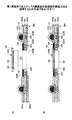
図6は、第2実施例である部品内蔵基板10Bを示している。尚、図6において、図1に示した第1実施例に係る部品内蔵基板10Aと対応する構成については同一符号を付して、その説明を省略する。
FIG. 6 shows a component built-in
前記した第1実施例に係る部品内蔵基板10Aでは、撮像デバイス110Bと第2の基板200とがフリップチップ接合される例を示した。これに対して本実施例に係る部品内蔵基板10Bは、撮像デバイス110Bを第2の基板200にワイヤ160を用いて接続したことを特徴としている。
In the component-embedded
ワイヤボンディング法は、フリップチップ法に比べて低コスト化が図れるが、ワイヤーループが撮像デバイス110Bの上部にも形成されるため、薄型化の点からは不利である。
The wire bonding method can reduce the cost as compared with the flip chip method, but is disadvantageous in terms of thinning because the wire loop is also formed on the
しかしながら本実施例では、撮像デバイス110Bの上部には開口部206が形成されており、この開口部206とレンズホルダ132とが作る内部空間内でワイヤ160のワイヤーループが形成されるよう構成している。よって、本実施例に係る部品内蔵基板10Bによれば、撮像デバイス110Bと第2の基板200との接続にワイヤ160を用いても部品内蔵基板10Bの薄型化を図ることができ、かつ低コスト化を図ることができる。
However, in this embodiment, an
以上、本発明の好ましい実施例について詳述したが、本発明は上記した特定の実施形態に限定されるものではなく、特許請求の範囲に記載された本発明の要旨の範囲内において、種々の変形・変更が可能なものである。 The preferred embodiments of the present invention have been described in detail above. However, the present invention is not limited to the specific embodiments described above, and various modifications can be made within the scope of the present invention described in the claims. It can be modified and changed.
具体的には、センサ表面を装置外部に露出して使用する各種装置に適用するこることが可能であり、例えば撮像デバイス110Bに代えてホトダイオードを用いた光学的センサや、感圧式や静電容量式の指紋センサとしての適用も可能である。
Specifically, the present invention can be applied to various devices that are used by exposing the sensor surface to the outside of the device. For example, an optical sensor using a photodiode instead of the
また、上記した実施例では、ガラス板130(透明部材)を撮像デバイス110B(第2の電子部品)に直接配設する構成を示したが、ガラス板130を撮像デバイス110B以外の部品(例えば、第2の基板200)に設けることも可能である。
Further, in the above-described embodiment, the configuration in which the glass plate 130 (transparent member) is directly disposed on the
10A,10B 部品内蔵基板
100 第1の基板
101 コア基板
102,202 ビアプラグ
103A,103B,203A,203B 配線パターン
103C 内層配線
104A,104B,204A,204B ソルダーレジスト層
110A 半導体チップ
110B 撮像デバイス
111 はんだボール
112 電極
113 銅コア
114 はんだ被膜
115 封止樹脂
129 撮像面
130 ガラス板
131 レンズ
132 レンズホルダ
140 異方性導電性樹脂
150 金型
160 ワイヤ
200 第2の基板
206 開口部
10A, 10B Component built-in
Claims (5)
その一面側に撮像領域を有する撮像素子である第2の電子部品と、
第1の配線が形成されると共に前記第1の電子部品の一面側が搭載される第1の基板と、
第2の配線が形成されると共に前記第1の基板に積層される第2の基板と、
前記第1の基板と前記第2の基板を電気的に接続する接続部材と、
前記第1の基板と前記第2の基板の間に前記第1の電子部品を封止するよう配設される封止樹脂とを有し、
前記第2の電子部品に、該第2の電子部品の一面側を保護する透明部材を設け、
前記第2の電子部品を、前記第2の基板の前記接続部材が接続されている面に配設し、
前記第2の基板に開口部を形成すると共に、前記第2の電子部品の一面側が該開口部と対向するよう配設し、
前記透明部材は、前記開口部の少なくとも一部の領域に位置している部品内蔵基板。 A first electronic component;
A second electronic component that is an imaging device having an imaging region on one side thereof ;
A first substrate on which a first wiring is formed and one surface side of the first electronic component is mounted;
A second substrate on which a second wiring is formed and stacked on the first substrate;
A connection member for electrically connecting the first substrate and the second substrate;
A sealing resin disposed between the first substrate and the second substrate to seal the first electronic component;
A transparent member that protects one surface side of the second electronic component is provided on the second electronic component,
Disposing the second electronic component on a surface of the second substrate to which the connection member is connected;
An opening is formed in the second substrate, and one surface side of the second electronic component is disposed so as to face the opening.
The transparent member is a component-embedded substrate located in at least a partial region of the opening .
その一面側に撮像領域を有する撮像素子である第2の電子部品と、
第1の配線が形成されると共に前記第1の電子部品の一面側が搭載される第1の基板と、
第2の配線が形成されると共に前記第1の基板に積層される第2の基板と、
前記第1の基板と前記第2の基板を電気的に接続する接続部材と、
前記第1の基板と前記第2の基板の間に前記第1の電子部品を封止するよう配設される封止樹脂とを有し、
前記第2の基板に開口部を形成すると共に、前記第2の電子部品の一面側が該開口部と対向し、
前記第2の電子部品の少なくとも一部が前記開口部の領域に位置するように設け、
前記第2の電子部品が、前記第2の基板とワイヤボンディングにより接続された部品内蔵基板。 A first electronic component;
A second electronic component that is an imaging device having an imaging region on one side thereof ;
A first substrate on which a first wiring is formed and one surface side of the first electronic component is mounted;
A second substrate on which a second wiring is formed and stacked on the first substrate;
A connection member for electrically connecting the first substrate and the second substrate;
A sealing resin disposed between the first substrate and the second substrate to seal the first electronic component;
An opening is formed in the second substrate, and one surface side of the second electronic component is opposed to the opening ,
Providing at least a part of the second electronic component so as to be located in a region of the opening;
A component-embedded substrate in which the second electronic component is connected to the second substrate by wire bonding.
Priority Applications (1)
| Application Number | Priority Date | Filing Date | Title |
|---|---|---|---|
| JP2007140141A JP4975523B2 (en) | 2007-05-28 | 2007-05-28 | Component built-in board |
Applications Claiming Priority (1)
| Application Number | Priority Date | Filing Date | Title |
|---|---|---|---|
| JP2007140141A JP4975523B2 (en) | 2007-05-28 | 2007-05-28 | Component built-in board |
Publications (3)
| Publication Number | Publication Date |
|---|---|
| JP2008294331A JP2008294331A (en) | 2008-12-04 |
| JP2008294331A5 JP2008294331A5 (en) | 2010-04-15 |
| JP4975523B2 true JP4975523B2 (en) | 2012-07-11 |
Family
ID=40168723
Family Applications (1)
| Application Number | Title | Priority Date | Filing Date |
|---|---|---|---|
| JP2007140141A Active JP4975523B2 (en) | 2007-05-28 | 2007-05-28 | Component built-in board |
Country Status (1)
| Country | Link |
|---|---|
| JP (1) | JP4975523B2 (en) |
Families Citing this family (5)
| Publication number | Priority date | Publication date | Assignee | Title |
|---|---|---|---|---|
| JP5619372B2 (en) * | 2009-04-16 | 2014-11-05 | 大日本印刷株式会社 | Image sensor module |
| KR101051540B1 (en) * | 2009-09-23 | 2011-07-22 | 삼성전기주식회사 | Printed circuit board |
| JP2014170893A (en) * | 2013-03-05 | 2014-09-18 | Taiyo Yuden Co Ltd | Camera module |
| JP6314070B2 (en) * | 2014-10-07 | 2018-04-18 | 新光電気工業株式会社 | Fingerprint recognition semiconductor device, method for manufacturing fingerprint recognition semiconductor device, and semiconductor device |
| JP6990029B2 (en) * | 2017-03-09 | 2022-01-12 | 株式会社アムコー・テクノロジー・ジャパン | Electronic devices and manufacturing methods for electronic devices |
Family Cites Families (4)
| Publication number | Priority date | Publication date | Assignee | Title |
|---|---|---|---|---|
| JP2001007472A (en) * | 1999-06-17 | 2001-01-12 | Sony Corp | Electronic circuit device and its manufacture |
| JP2004079779A (en) * | 2002-08-19 | 2004-03-11 | Seiko Precision Inc | Solid state imaging device |
| JP4475875B2 (en) * | 2003-02-26 | 2010-06-09 | イビデン株式会社 | Printed wiring board |
| WO2006035528A1 (en) * | 2004-09-29 | 2006-04-06 | Murata Manufacturing Co., Ltd. | Stack module and method for manufacturing the same |
-
2007
- 2007-05-28 JP JP2007140141A patent/JP4975523B2/en active Active
Also Published As
| Publication number | Publication date |
|---|---|
| JP2008294331A (en) | 2008-12-04 |
Similar Documents
| Publication | Publication Date | Title |
|---|---|---|
| JP5934109B2 (en) | Camera module with molded tape flip chip imaging device mounting and manufacturing method | |
| KR100661169B1 (en) | Packaging chip and packaging method thereof | |
| JP5289582B2 (en) | Imaging device and imaging device module | |
| JP5964858B2 (en) | Image pickup device storage package and image pickup apparatus | |
| JP6732932B2 (en) | Base for mounting image pickup element, image pickup device, and image pickup module | |
| WO2012002378A1 (en) | Wiring substrate, image pickup device, and image-pickup device module | |
| JP2003189195A (en) | Semiconductor device, imaging semiconductor device, and its manufacturing method | |
| US11646331B2 (en) | Package substrate | |
| JP5054440B2 (en) | Manufacturing method of electronic component built-in substrate and electronic component built-in substrate | |
| JP4950743B2 (en) | Multilayer wiring board and manufacturing method thereof | |
| JP4975523B2 (en) | Component built-in board | |
| US8440915B2 (en) | Device mounting board and semiconductor module | |
| JPWO2019082923A1 (en) | Imaging element mounting board, imaging device and imaging module | |
| JP5110163B2 (en) | Manufacturing method of module with built-in components | |
| JP5128180B2 (en) | Chip built-in substrate | |
| KR20150135048A (en) | Printed circuit board, method for manufacturing the same and package on packaage having the thereof | |
| JP5299106B2 (en) | Image sensor module | |
| JP2010040721A (en) | Semiconductor module, semiconductor device, portable apparatus, and manufacturing method of semiconductor module, and manufacturing method of semiconductor device | |
| JP2010118436A (en) | Manufacturing method for module with built-in component | |
| JP2004266271A (en) | Electronic part mounting body and method for manufacturing the same | |
| US10757310B1 (en) | Miniature image pickup module and manufacturing method thereof | |
| JP4285140B2 (en) | Manufacturing method of semiconductor device | |
| JP2004311668A (en) | Semiconductor device, electronic device, and sealing die | |
| KR100780189B1 (en) | Camera module having substrate of non-shrink ltcc-m | |
| JP2005197344A (en) | Print-circuit board and its manufacturing method |
Legal Events
| Date | Code | Title | Description |
|---|---|---|---|
| A521 | Request for written amendment filed |
Free format text: JAPANESE INTERMEDIATE CODE: A523 Effective date: 20100301 |
|
| A621 | Written request for application examination |
Free format text: JAPANESE INTERMEDIATE CODE: A621 Effective date: 20100301 |
|
| A131 | Notification of reasons for refusal |
Free format text: JAPANESE INTERMEDIATE CODE: A131 Effective date: 20111101 |
|
| A521 | Request for written amendment filed |
Free format text: JAPANESE INTERMEDIATE CODE: A523 Effective date: 20111228 |
|
| TRDD | Decision of grant or rejection written | ||
| A01 | Written decision to grant a patent or to grant a registration (utility model) |
Free format text: JAPANESE INTERMEDIATE CODE: A01 Effective date: 20120403 |
|
| A01 | Written decision to grant a patent or to grant a registration (utility model) |
Free format text: JAPANESE INTERMEDIATE CODE: A01 |
|
| A61 | First payment of annual fees (during grant procedure) |
Free format text: JAPANESE INTERMEDIATE CODE: A61 Effective date: 20120411 |
|
| R150 | Certificate of patent or registration of utility model |
Ref document number: 4975523 Country of ref document: JP Free format text: JAPANESE INTERMEDIATE CODE: R150 Free format text: JAPANESE INTERMEDIATE CODE: R150 |
|
| FPAY | Renewal fee payment (event date is renewal date of database) |
Free format text: PAYMENT UNTIL: 20150420 Year of fee payment: 3 |