JP4972981B2 - Magnetic recording / reproducing apparatus and magnetic recording / reproducing method - Google Patents
Magnetic recording / reproducing apparatus and magnetic recording / reproducing method Download PDFInfo
- Publication number
- JP4972981B2 JP4972981B2 JP2006111899A JP2006111899A JP4972981B2 JP 4972981 B2 JP4972981 B2 JP 4972981B2 JP 2006111899 A JP2006111899 A JP 2006111899A JP 2006111899 A JP2006111899 A JP 2006111899A JP 4972981 B2 JP4972981 B2 JP 4972981B2
- Authority
- JP
- Japan
- Prior art keywords
- recording
- signal
- track
- unit
- tracks
- Prior art date
- Legal status (The legal status is an assumption and is not a legal conclusion. Google has not performed a legal analysis and makes no representation as to the accuracy of the status listed.)
- Expired - Fee Related
Links
Images


Classifications
-
- G—PHYSICS
- G11—INFORMATION STORAGE
- G11B—INFORMATION STORAGE BASED ON RELATIVE MOVEMENT BETWEEN RECORD CARRIER AND TRANSDUCER
- G11B20/00—Signal processing not specific to the method of recording or reproducing; Circuits therefor
- G11B20/22—Signal processing not specific to the method of recording or reproducing; Circuits therefor for reducing distortions
-
- G—PHYSICS
- G11—INFORMATION STORAGE
- G11B—INFORMATION STORAGE BASED ON RELATIVE MOVEMENT BETWEEN RECORD CARRIER AND TRANSDUCER
- G11B20/00—Signal processing not specific to the method of recording or reproducing; Circuits therefor
- G11B20/10—Digital recording or reproducing
- G11B20/10009—Improvement or modification of read or write signals
-
- G—PHYSICS
- G11—INFORMATION STORAGE
- G11B—INFORMATION STORAGE BASED ON RELATIVE MOVEMENT BETWEEN RECORD CARRIER AND TRANSDUCER
- G11B5/00—Recording by magnetisation or demagnetisation of a record carrier; Reproducing by magnetic means; Record carriers therefor
- G11B5/008—Recording on, or reproducing or erasing from, magnetic tapes, sheets, e.g. cards, or wires
- G11B5/00813—Recording on, or reproducing or erasing from, magnetic tapes, sheets, e.g. cards, or wires magnetic tapes
- G11B5/00817—Recording on, or reproducing or erasing from, magnetic tapes, sheets, e.g. cards, or wires magnetic tapes on longitudinal tracks only, e.g. for serpentine format recording
- G11B5/00821—Recording on, or reproducing or erasing from, magnetic tapes, sheets, e.g. cards, or wires magnetic tapes on longitudinal tracks only, e.g. for serpentine format recording using stationary heads
- G11B5/00826—Recording on, or reproducing or erasing from, magnetic tapes, sheets, e.g. cards, or wires magnetic tapes on longitudinal tracks only, e.g. for serpentine format recording using stationary heads comprising a plurality of single poles or gaps or groups thereof operative at the same time
- G11B5/0083—Recording on, or reproducing or erasing from, magnetic tapes, sheets, e.g. cards, or wires magnetic tapes on longitudinal tracks only, e.g. for serpentine format recording using stationary heads comprising a plurality of single poles or gaps or groups thereof operative at the same time for parallel information processing, e.g. PCM recording
-
- G—PHYSICS
- G11—INFORMATION STORAGE
- G11B—INFORMATION STORAGE BASED ON RELATIVE MOVEMENT BETWEEN RECORD CARRIER AND TRANSDUCER
- G11B2220/00—Record carriers by type
- G11B2220/90—Tape-like record carriers
-
- G—PHYSICS
- G11—INFORMATION STORAGE
- G11B—INFORMATION STORAGE BASED ON RELATIVE MOVEMENT BETWEEN RECORD CARRIER AND TRANSDUCER
- G11B5/00—Recording by magnetisation or demagnetisation of a record carrier; Reproducing by magnetic means; Record carriers therefor
- G11B5/48—Disposition or mounting of heads or head supports relative to record carriers ; arrangements of heads, e.g. for scanning the record carrier to increase the relative speed
- G11B5/58—Disposition or mounting of heads or head supports relative to record carriers ; arrangements of heads, e.g. for scanning the record carrier to increase the relative speed with provision for moving the head for the purpose of maintaining alignment of the head relative to the record carrier during transducing operation, e.g. to compensate for surface irregularities of the latter or for track following
- G11B5/584—Disposition or mounting of heads or head supports relative to record carriers ; arrangements of heads, e.g. for scanning the record carrier to increase the relative speed with provision for moving the head for the purpose of maintaining alignment of the head relative to the record carrier during transducing operation, e.g. to compensate for surface irregularities of the latter or for track following for track following on tapes
Landscapes
- Engineering & Computer Science (AREA)
- Signal Processing (AREA)
- Signal Processing For Digital Recording And Reproducing (AREA)
- Digital Magnetic Recording (AREA)
Description
本発明は、磁気記録メディアに複数のトラックを一または複数の記録ヘッドにより記録し、その複数のトラックから一または複数の再生ヘッドにより信号を再生する磁気記録再生装置及び磁気記録再生方法に関する。 The present invention relates to a magnetic recording / reproducing apparatus and a magnetic recording / reproducing method for recording a plurality of tracks on a magnetic recording medium with one or a plurality of recording heads and reproducing a signal from the plurality of tracks with one or a plurality of reproducing heads.
近年、磁気ヘッドにおいては、磁気記録メディアの大容量化を図るために、更なる高密度記録が求められ、トラックのトラック幅を狭くすること(以下、「狭幅化」という。)に適した磁気ヘッドが採用されるようになってきている。一般的には、トラックの狭幅化にはトラック・サーボの精度向上が鍵となる。 In recent years, magnetic heads are required to have higher density recording in order to increase the capacity of magnetic recording media, and are suitable for narrowing the track width of tracks (hereinafter referred to as “narrowing”). Magnetic heads have been adopted. In general, improving the accuracy of the track servo is the key to narrowing the track.
磁気テープ記録再生装置においては、狭幅化に伴い、サーボが困難になる対策案として、所謂ノントラッキング・システムが提唱され、実用化に至っている(たとえば特許文献1−5など)。このノントラッキング方式は、ヘリカルスキャンにてダブルアジマス記録を行ったトラックに対し、識別のために、ブロックに分けてデータを記録することによって、目的のトラックを1回のトレースで再生できなくても、データを再構成できるものである。このノントラッキング方式によって、従来のトラック・サーボで必要とされる1トラック以内のトラック制御に対して、4倍以上のマージンが許容されるようになる。 In a magnetic tape recording / reproducing apparatus, a so-called non-tracking system has been proposed as a countermeasure for making servo difficult as the width becomes narrower, and has been put into practical use (for example, Patent Documents 1-5). In this non-tracking method, even if the target track cannot be reproduced in a single trace by recording the data in blocks for identification, the track that has been double-azimuth recorded by the helical scan is recorded. The data can be reconstructed. With this non-tracking method, a margin of 4 times or more is allowed for track control within one track required by the conventional track servo.
また、ノントラッキング技術は、ヘリカル・スキャンに留まらずリニア記録で使用されるための可能性が検討されている(たとえば特許文献6,7など)。 Further, the possibility of using non-tracking technology not only in helical scanning but also in linear recording has been studied (for example, Patent Documents 6 and 7).
ところで、磁気記録メディアの基板に、たとえばポリエステルフィルムのような伸縮性をもった非磁性支持体を使用した場合、ダブルアジマス記録を行ったとしても、許容できる変形量はトラック・サーボを併用して、例えばトラック幅の2倍程度までであり、これ以上の変形が発生する場合は、十分なSN比をもって信号を再生することができなかった。また、ダブルアジマスを持たない記録の場合では、トラックをまたがない所謂ガードバンドの幅を、トラック・サーボを併用した状態でも、エラーレート等の信頼性を劣化させないために、テープの変形量以下に押さえ込む必要があった。 By the way, when a non-magnetic support having elasticity such as a polyester film is used for the magnetic recording medium substrate, even if double azimuth recording is performed, the allowable deformation amount is obtained by using a track servo. For example, when it is up to about twice the track width and further deformation occurs, the signal cannot be reproduced with a sufficient SN ratio. Also, in the case of recording without double azimuth, the width of the so-called guard band that does not cross the track is less than the amount of deformation of the tape so as not to deteriorate the reliability such as error rate even when the track servo is used. It was necessary to hold in.
このような問題は、これまで実現されていた信号再生方式においては、少なくとも1つの再生ヘッドが同時に複数のトラックから信号を読み込むことによって信号品質が著しく劣化することに起因する。それを回避するために、ガードバンドやダブルアジマス記録を行い、また再生ヘッドからは1つのトラックからの信号のみを拾うように工夫されてきた。
しかし、さらに高トラック密度化を行う場合においては、先ずガードバンドの設置はその妨げとなる。また、再生時において隣接するトラックからの干渉を少なくすることができるダブルアジマス記録は、狭幅化した場合その効果は減少してしまう。
Such a problem is caused by the fact that in the signal reproduction method that has been realized so far, the signal quality is significantly deteriorated when at least one reproduction head reads signals from a plurality of tracks simultaneously. In order to avoid this, it has been devised to perform guard band and double azimuth recording and to pick up only the signal from one track from the reproducing head.
However, when the track density is further increased, the installation of the guard band first hinders the installation. Also, the effect of double azimuth recording, which can reduce interference from adjacent tracks during reproduction, is reduced when the width is narrowed.
このことは、ノントラッキング方式であっても同じであり、再生ヘッドは複数のトラックに跨って信号を再生するように見えるが、時間分割した場合、再生している信号は常に1つのトラックに対してだけであり、同一時間に複数のトラックを再生するということは行っていなかった。 This is the same even in the non-tracking method, and the reproducing head seems to reproduce the signal across a plurality of tracks. However, when time division is performed, the signal being reproduced always corresponds to one track. It wasn't going to play multiple tracks at the same time.
また、ノントラッキング方式で高トラック密度化に対応しようとした際に、対象トラックの隣接するトラックからの信号を拾うことによってノイズが混入するようになるためトラックの狭幅化対応が限界になってきている。 Also, when trying to cope with higher track density with the non-tracking method, noise is mixed in by picking up signals from the adjacent track of the target track, so the narrowing of the track becomes a limit. ing.
磁気ヘッド装置の背景技術には、単一の磁気ヘッド素子を有する磁気記録ヘッド層又は磁気再生ヘッド層が、非磁性材料からなる基材に複数積層され、すべての磁気ヘッド素子が積層方向に対して、ほぼ直交する方向(以下、「ヘッド幅方向」という。)にずらして形成されたものがある(たとえば特許文献8、特許文献9など)。 In the background art of a magnetic head device, a plurality of magnetic recording head layers or magnetic reproducing head layers having a single magnetic head element are laminated on a substrate made of a non-magnetic material, and all the magnetic head elements are arranged in the lamination direction. Thus, there are those formed so as to be shifted in a substantially orthogonal direction (hereinafter referred to as “head width direction”) (for example, Patent Document 8, Patent Document 9, etc.).
このほか、記録密度を向上させるために、1つのブロックに複数のヘッドを配置し、同一アジマスのブロックで形成する方式として、一度に複数のデータ・フレームを記録する技術がある(たとえば特許文献10及び特許文献11など)。 In addition, in order to improve the recording density, there is a technique in which a plurality of heads are arranged in one block and the blocks are formed of the same azimuth, and a plurality of data frames are recorded at one time (for example, Patent Document 10). And Patent Document 11).
これらの公知技術は、再生ヘッド幅をトラックの幅の半分程度にしなければならなくなるため、再生信号の出力を大きくとることができないという制約が生じ、たとえばSN比の確保の点で不利であり、更なる高密度記録化には必ずしも向いていなかった。 Since these known techniques require that the reproducing head width be about half the width of the track, there is a restriction that the output of the reproducing signal cannot be made large, which is disadvantageous, for example, in securing the SN ratio. It was not necessarily suitable for higher density recording.
MIMO(Multi-Input/Multi-Output)技術は、無線通信に用いられるものとして広く知られている(たとえば特許文献12など)。 MIMO (Multi-Input / Multi-Output) technology is widely known as one used for wireless communication (for example, Patent Document 12).
また、MIMOに関する技術を磁気記録に使用する技術も知られている(たとえば非特許文献1など)。しかし、たとえば記録したトラックよりも広幅の再生ヘッドを使用する場合など、実用化に際して発生する課題が解決されていなかった。 In addition, a technique using a technique related to MIMO for magnetic recording is also known (for example, Non-Patent Document 1). However, for example, when a reproducing head having a width wider than that of a recorded track is used, problems that occur in practical use have not been solved.
本発明においては、MIMOを使用した磁気記録方法としては前項で紹介した論文をもって実現しえなかった、磁気記録再生方法へのMIMO技術の実用化を実現するにあたり、公知技術からは予見しえなかった技術内容を明らかにするものである。
上述したように従来の磁気記録再生方式では、記録密度を高めるために、磁気記録メディアでのトラック幅を狭くする方法が採用されてきた。しかし、このまま高記録密度を追い求めてトラック幅を狭くしていくと、再生時にトラックを追いきれなくなるという問題が生じる。そこで、トラックに対する再生ヘッドの位置が多少とも外れていても、そのトラックから信号を読み取ることができるノントラッキング方式が提案されている。しかしながら、ノントラッキング方式で適切に再生信号を得るためには、再生ヘッドの設定に厳しい制約が伴う。この面からトラック幅の狭小化による高記録密度化には限界があった。 As described above, in the conventional magnetic recording / reproducing system, a method of narrowing the track width on the magnetic recording medium has been adopted in order to increase the recording density. However, if the track width is narrowed in pursuit of a high recording density as it is, there arises a problem that the track cannot be tracked during reproduction. Therefore, a non-tracking method has been proposed in which a signal can be read from the track even if the position of the reproducing head is slightly deviated from the track. However, in order to obtain a reproduction signal appropriately by the non-tracking method, severe restrictions are imposed on the setting of the reproduction head. From this aspect, there is a limit to increasing the recording density by narrowing the track width.
そこで、再生ヘッドの幅を決める制約を軽減して、トラック幅の狭小化、高記録密度化を実現することのできる、マルチトラックによる磁気記録再生装置を実現するための技術開発が本発明者らによって行われている。 Therefore, the present inventors have developed a technology for realizing a multi-track magnetic recording / reproducing apparatus capable of reducing the restriction for determining the width of the reproducing head and realizing a narrow track width and a high recording density. Has been done by.
しかしながら、かかる磁気記録再生装置を実現するためには、解決すべき課題が残されており、その一つに、隣接するトラック信号の位相ずれによる再生信号の振幅減少が挙げられる。 However, in order to realize such a magnetic recording / reproducing apparatus, there remains a problem to be solved, and one of them is a decrease in the amplitude of a reproduced signal due to a phase shift between adjacent track signals.
本発明は、かかる事情を鑑み、トラック幅の狭小化、高記録密度化が可能な、マルチトラック方式による磁気記録再生装置であって、隣接するトラック信号の位相ずれによる再生信号の振幅減少の問題を解消することのできる磁気記録再生装置及び磁気記録再生方法を提供しようとするものである。 In view of such circumstances, the present invention is a multi-track magnetic recording / reproducing apparatus capable of narrowing the track width and increasing the recording density, and has a problem of reducing the amplitude of the reproduced signal due to a phase shift between adjacent track signals. It is an object of the present invention to provide a magnetic recording / reproducing apparatus and a magnetic recording / reproducing method capable of eliminating
上記の課題を解決するために、本発明の磁気記録再生装置は、磁気記録メディアに記録ヘッドにより、データ検出のための信号処理を行う際に一単位となる複数のトラックを、隣り合う2つのトラックがトラック幅方向において一部が重なり合うように記録する記録部と、前記磁気記録メディアの複数の前記トラックに跨って信号を再生することが可能とされ、それぞれ前記記録ヘッドの記録ヘッド幅以上の再生ヘッド幅を有する複数の再生ヘッドにより、前記複数のトラックそれぞれの信号を、前記複数のトラックに対して異なる位置関係で複数再生し、これら再生信号を前記一単位にまとめ、信号処理を行うことで、前記トラックごとの再生信号を生成する再生部と、前記隣接する各トラックに単一周波数の繰り返し信号である学習信号を記録し、前記再生部により再生された信号の振幅値をもとに、隣り合う各トラックの一方のトラックに記録する信号の、他方のトラックに記録する信号に対する最適な遅延量を設定することによって、前記記録部によって前記磁気記録メディアに記録される複数のトラックの中の隣り合うトラック間の記録信号の位相を合わせる位相合わせ手段とを具備する。
In order to solve the above problems, a magnetic recording / reproducing apparatus according to the present invention includes a plurality of tracks adjacent to each other as a unit when performing signal processing for data detection on a magnetic recording medium by a recording head . It is possible to reproduce a signal across a plurality of tracks of the magnetic recording medium, and a recording unit that records the track so that a part of the track overlaps in the track width direction , each of which is greater than the recording head width of the recording head A plurality of reproducing heads having a reproducing head width are used to reproduce a plurality of signals of each of the plurality of tracks with different positional relationships with respect to the plurality of tracks, and the reproduced signals are combined into the unit to perform signal processing. in a reproducing section for generating a reproduced signal of each of the tracks, the learning signal is a repeat signal of a single frequency in each track to the adjacent By setting the optimum delay amount of the signal recorded on one track of the adjacent tracks and the signal recorded on the other track based on the amplitude value of the signal recorded and reproduced by the reproducing unit And a phase adjusting means for adjusting a phase of a recording signal between adjacent tracks among a plurality of tracks recorded on the magnetic recording medium by the recording unit.
この発明によれば、位相合わせ手段にて、記録部によって磁気記録メディアに記録される複数のトラックの中の隣接するトラック間の記録信号の位相を合わせるように構成したことによって、トラック幅の狭小化、高記録密度化が可能な磁気記録再生装置の実現化にあたって、隣接するトラック信号の位相ずれによる再生信号の振幅減少の問題を解消することができる。 According to the present invention, the phase adjusting means is configured to adjust the phase of the recording signal between adjacent tracks among the plurality of tracks recorded on the magnetic recording medium by the recording unit, thereby reducing the track width. In the realization of a magnetic recording / reproducing apparatus capable of increasing the recording density and increasing the recording density, it is possible to eliminate the problem of the amplitude reduction of the reproduced signal due to the phase shift of the adjacent track signals.
その位相合わせ手段のより具体的な構成に関しては、隣接するトラックの一方のトラックに記録する信号に対する他方のトラックに記録する信号の遅延量を制御して、前記隣接する各トラックに同一の学習信号を記録し、再生部により再生された信号をもとに最適な遅延量を設定する手段が挙げられる。ここで、同一の学習信号は、単一周波数の繰り返し信号とする。 With regard to a more specific configuration of the phase matching means, the same learning signal is used for each adjacent track by controlling the delay amount of the signal recorded on the other track relative to the signal recorded on one track of the adjacent track. And an optimum delay amount is set based on the signal reproduced by the reproduction unit. Here, the same learning signal is a single frequency repetitive signal.
さらに、具体的には、位相合わせ手段は、再生された信号の振幅値をもとに最適な遅延量を設定するものとする。 More specifically, the phase matching means sets an optimum delay amount based on the amplitude value of the reproduced signal.
あるいは、位相合わせ手段は、精度を段階的に上げながら、複数の回に分けて最適な遅延量を絞り込むものとしてもよいし、最急降下法を用いて最適な遅延量を設定するものであってもよい。 Alternatively, the phase matching unit may narrow down the optimum delay amount in a plurality of times while increasing the accuracy step by step, or set the optimum delay amount using the steepest descent method. Also good.
以上説明したように、本発明によれば、トラック幅の狭小化、高記録密度化が可能な、マルチトラック方式による磁気記録再生装置において、隣接するトラック信号の位相ずれによる再生信号の振幅減少の問題を解消することができる。 As described above, according to the present invention, in a multi-track magnetic recording / reproducing apparatus capable of narrowing the track width and increasing the recording density, it is possible to reduce the amplitude of the reproduced signal due to the phase shift between adjacent track signals. The problem can be solved.
以下、本発明を実施した形態を図面に基づき詳細に説明する。 Hereinafter, embodiments of the present invention will be described in detail with reference to the drawings.
(第1の実施形態) (First embodiment)
図1は本発明の一実施形態であるマルチヘッドおよびマルチトラックを用いた磁気記録再生装置の構成を示す図である。なお、記録ヘッドの数はMとし、再生ヘッドの数はNとする。なお、ここでM=3、N=3の場合について説明する。同図に示すように、この磁気記録再生装置は、記録部100と再生部200を備える。 FIG. 1 is a diagram showing a configuration of a magnetic recording / reproducing apparatus using a multi-head and a multi-track according to an embodiment of the present invention. Note that the number of recording heads is M and the number of reproducing heads is N. Here, the case where M = 3 and N = 3 will be described. As shown in the figure, the magnetic recording / reproducing apparatus includes a recording unit 100 and a reproducing unit 200.
記録部100は、マルチトラック化部110、マルチトラック記録符号化部120、マルチトラック分離パターン付加部130、マルチトラック記録部140、記録ヘッドアレイ150で構成される。
The recording unit 100 includes a
マルチトラック化部110は、マルチトラック化のために記録データ1を記録ヘッドアレイ150に設けられた記録ヘッド151,152,153の数(M=3)のデータに振り分けるデータ分配器111で構成される。マルチトラック記録符号化部120は、データ分配器111にて振り分けられた記録データを符号化するM個の記録符号化部121,122,123で構成される。マルチトラック分離パターン付加部130は、符号化された記録データにプリアンブルを付加するM個のプリアンブル付加部131,132,133で構成される。マルチトラック記録部140は、プリアンブルが付加された記録データに所望のタイミングを与えるM個の出力タイミング設定部141,142,143と、記録補償処理を行うM個の記録補償部144,145,146と、記録補償処理後の記録データをもとに個々の記録ヘッド151,152,153を駆動するM個の記録アンプ147,148,149とで構成される。
The
一方、再生部200は、再生ヘッドアレイ210、チャネル再生部220、信号分離部230、マルチトラック復調部240、復元部260を備える。
On the other hand, the reproducing unit 200 includes a reproducing
再生ヘッドアレイ210は、磁気記録メディア2に記録された各トラックから信号を読み出すN(たとえば3)個の再生ヘッド211,212,213を有する。
The reproducing
チャネル再生部220は、再生ヘッドアレイ210に搭載されたN個(N=3)の再生ヘッド211,212,213によって再生された信号を増幅するN個の再生アンプ221,222,223と、N個の再生アンプ221,222,223の出力の振幅レベルが所定の値になるようにゲインを制御するAGC224,225,226と、AGC224,225,226の出力を所定のビット幅のディジタル値に量子化するA/Dコンバータ227,228,229とを備える。なお、A/Dコンバータ227,228,229の直前には必要に応じて不要な高域成分を除去するローパス・フィルタが備えられていてもよい。
The
信号分離部230は、A/Dコンバータ227,228,229の出力から前記分離パターンの開始位置を知るための同期信号の検出を行う前段の同期信号検出器231と、同期信号検出器231によって検出された同期信号をもとに分離パターンの開始位置を特定して、その分離パターンを用いてチャネル推定演算および信号分離演算を行うことによって、複数の再生ヘッド211,212,213によってそれぞれ再生された1ユニット分の再生信号からトラックごとの再生信号を分離する信号分離処理部232とを備える。
The
マルチトラック復調部240は、トラックごとに分離された再生信号に対して等化処理を行うM個の等化器241,242,243と、等化器241,242,243の出力からビット同期を行うM個のPLL244,245,246と、各トラックの再生信号を二値化して符号語列を生成するM個の検出器247,248,249と、検出器247,248,249の出力である2値化された再生信号から符号語列上の同期信号を検出するM個の後段の同期信号検出器250,251,252と、後段の同期信号検出器250,251,252により検出されたデータ領域の同期信号でデータの開始位置を特定して復号するM個の復号器253,254,255とを備える。
The
復元部260は、M個の復号器253,254,255より出力された各トラックのデータを、記録時と逆の動作により連結して再生データ3を復元するデータ結合器261を備える。
The
以上、記録部100と再生部200の構成について説明したが、この実施形態の磁気記録再生装置には、位相情報を再生部から記録部に送る手段として、位相制御信号発生器90が設けられている。これは、磁気記録メディア2に記録される複数のトラックの中の隣接するトラックの記録信号の位相を合わせるための制御を行う機能をもつ。
Although the configurations of the recording unit 100 and the reproducing unit 200 have been described above, the magnetic recording / reproducing apparatus of this embodiment is provided with the phase
次に、この実施形態の磁気記録再生装置の基本的な記録と再生の動作について説明する。 Next, basic recording and reproducing operations of the magnetic recording / reproducing apparatus of this embodiment will be described.
まず、記録の動作から説明する。図2は記録の動作に関するフローチャートである。記録部100では、まず、入力された記録データ1がマルチトラック化部110にて、記録ヘッド151,152,153の数(M=3)のデータ(トラックごとのデータ)に分配される(ステップS101)。分配された各データは、それぞれマルチトラック記録符号化部120の記録符号化部121,122,123にて、磁気記録メディア2の記録再生特性を考慮した符号語列に符号化される。このとき符号語列に、同期信号などデータ復調時に必要な情報も付加される(ステップS102)。
First, the recording operation will be described. FIG. 2 is a flowchart regarding the recording operation. In the recording unit 100, first, the
次に、生成された各符号語列の所定の位置に対して、マルチトラック分離パターン付加部130のプリアンブル付加部131,132,133にてプリアンブル符号が与えられ、記録符号列が得られる(ステップS103)。プリアンブル符号は、各再生ヘッドによってそれぞれ読み出された各再生信号を処理単位として所定の信号処理によってトラックごとの信号を分離するために用いられる分離パターンであり、マルチトラック記録符号化部120の記録符号化部121,122,123で発生された符号語列の規則を考慮して作成されたものである。
Next, a preamble code is given to the predetermined position of each generated codeword string by the
さらに、それぞれのトラックごとの記録符号列は、マルチトラック記録部140の出力タイミング設定部141,142,143にて所望のタイミングが与えられた後、記録補償部144,145,146にて、磁気記録メディア2への記録に最適化するための記録補償処理が施される。この後、トラックごとの記録符号列は、記録アンプ147,148,149において電圧から電流に変換されて記録ヘッド151,152,153に送られ、記録ヘッド151,152,153によって磁気記録メディア2に記録される(ステップS104)。
Further, the recording code string for each track is given a desired timing by the output
次に、再生の基本的な動作を説明する。図3は再生の動作に関するフローチャートである。 Next, the basic operation of reproduction will be described. FIG. 3 is a flowchart regarding the reproduction operation.
再生部200では、まず、N(たとえば3)個の再生ヘッド211,212,213によって、磁気記録メディア2の各トラックから信号が再生される(ステップS201)。次に、AGC224,225,226にて、各再生アンプ221,222,223の出力の振幅レベルが調整された後、AGC224,225,226の出力はA/Dコンバータ227,228,229にてディジタル値に変換されて同期信号検出器231に出力される(ステップS202)。同期信号検出器231では、A/Dコンバータ227,228,229の出力から分離パターンの開始位置を知るための同期信号の検出が行われる(ステップS203)。信号分離処理部232では、検出された同期信号をもとに各再生信号に配置されている分離パターンの開始位置を特定し、その分離パターンを用いて所定のチャネル推定演算を行う(ステップS204)。さらに、信号分離処理部232では、そのチャネル推定演算の結果と1ユニット分の再生信号とからトラックごとの再生信号を生成する処理が行われる(ステップS205)。
In the reproducing unit 200, first, a signal is reproduced from each track of the
この後は、マルチトラック復調部240の各等化器241,242,243にて、トラックごとに分離された再生信号に対して等化処理が行われ、PLL244,245,246でビット同期された信号は検出器247,248,249にてトラックごとの再生信号の二値化が行われることによってトラックごとの符号語列が生成される。さらに、後段の同期信号検出器250,251,252にて、トラックごとの符号語列上の同期信号の検出、復号器253,254,255でのトラックごとの符号語列からの同期信号を用いたデータ列の復号が行われる。そして復元部260にてトラックごとのデータが連結されて再生データが得られる(ステップS206)。
Thereafter, the
次に、本実施形態の磁気記録再生装置における記録ヘッド及び再生ヘッドの構成を従来の典型的な記録ヘッド及び再生ヘッドの構成との比較により説明する。 Next, the configuration of the recording head and the reproducing head in the magnetic recording / reproducing apparatus of the present embodiment will be described by comparison with the conventional typical recording head and reproducing head configuration.
図4(a)は、従来のリニア方式における、記録ヘッドパターン、メディア記録パターン、並びに再生ヘッドパターンを示している。記録ヘッド幅をTwとし、全ての記録ヘッドの幅Twは同一であるとする。また再生ヘッド幅をTrとし、全ての再生ヘッドTrの幅は同一であるとする。隣り合う記録ヘッドのトラック中心間の距離をDtとする。各トラックの磁化方向、いわゆるアジマス方向は同一とする。 FIG. 4A shows a recording head pattern, a media recording pattern, and a reproducing head pattern in the conventional linear method. It is assumed that the recording head width is Tw and the width Tw of all the recording heads is the same. Further, it is assumed that the reproducing head width is Tr, and all reproducing heads Tr have the same width. Let Dt be the distance between the track centers of adjacent recording heads. The magnetization direction of each track, the so-called azimuth direction, is the same.
同図に示すように、従来の構成においては、Dtは記録ヘッドがトラック幅方向に離間して配置されていることから記録ヘッド幅Twよりも大きい。また、再生ヘッド幅Trは、メディアに記録されているパターン幅すなわち記録ヘッド幅Twよりも小さく設定され、単一のトラックからのみ信号を得ることができる。 As shown in the figure, in the conventional configuration, Dt is larger than the recording head width Tw because the recording heads are spaced apart in the track width direction. The reproducing head width Tr is set smaller than the pattern width recorded on the medium, that is, the recording head width Tw, and a signal can be obtained only from a single track.
なお、記録ヘッドアレイ150において、複数の記録ヘッドを一つのモジュールに実装するためには、記録ヘッドの間に一定の間隔を設ける必要がある。このため、図4(a)に示すように、複数の記録ヘッドをトラック幅方向に直列に配置する場合は、Dtが記録ヘッド幅Twよりも大きくなる。一方、再生ヘッド幅Trは、記録ヘッド幅Twよりも小さいことより、再生ヘッド幅Trは距離Dtよりもさらに小さくなる。
In the
上記のように、従来は、各トラックの信号を別々に読み取るようにするために、再生ヘッド幅Trを大きく設定することが困難であった。また、高トラック密度化を実現するために、たとえば、記録ヘッド幅Twを小さくしたり、あるいは、メディアに記録する信号がトラック幅方向に部分的に重なるように記録したりすると、再生ヘッド幅Trをよりいっそう小さく設定しなければならなくなり、実装が困難になるとともに、再生特性が劣化するおそれがあった。 As described above, conventionally, it has been difficult to set the reproducing head width Tr large in order to read the signals of each track separately. In order to realize a high track density, for example, when the recording head width Tw is reduced or recording is performed so that signals to be recorded on the medium partially overlap in the track width direction, the reproducing head width Tr Must be set even smaller, which makes mounting difficult and may cause deterioration in reproduction characteristics.
図4(b)は、本実施形態における、記録ヘッドパターン、メディア記録パターン、並びに再生ヘッドパターンの例を示す図である。同図に示すように、本実施形態において、各記録ヘッドは磁気記録メディアの走行方向において隣接するヘッド間で所定の間隔を設け、かつトラック幅方向においては隣接する記録ヘッドで書かれたトラックの一部が重なる位置関係で配置されている。すなわち、Dtは記録ヘッド幅Twよりも小さい値に設定されている。このため、隣り合う2つのトラックのメディア記録パターンは互いにトラック幅方向において一部が重なり合っている。また、各記録ヘッドは磁気記録メディアの走行方向に互いにずらして配置されていることで、2つのメディア記録パターンが重なった領域では、時間的に後方で記録を行う記録ヘッドによるメディア記録パターンで、時間的に前方で別の記録ヘッドによって記録されたメディア記録パターンに対して重ね書きされる。 FIG. 4B is a diagram illustrating an example of a recording head pattern, a media recording pattern, and a reproducing head pattern in the present embodiment. As shown in the figure, in this embodiment, each recording head has a predetermined interval between adjacent heads in the running direction of the magnetic recording medium, and tracks written by the adjacent recording heads in the track width direction. They are arranged so that some of them overlap. That is, Dt is set to a value smaller than the recording head width Tw. For this reason, media recording patterns of two adjacent tracks partially overlap each other in the track width direction. In addition, each recording head is arranged so as to be shifted from each other in the traveling direction of the magnetic recording medium, so that in a region where two media recording patterns overlap, it is a media recording pattern by a recording head that performs recording in the back in time, It is overwritten with respect to a media recording pattern recorded by another recording head in front of time.
一方、各再生ヘッドも、各記録ヘッドと同様に磁気記録メディアの走行方向に互いにずらして配置されている。ここで、再生ヘッド幅Trは、従来のように記録ヘッド幅Twよりも小さく設定しなくてもよく、たとえば記録ヘッド幅Twと同等あるいはそれ以上の値に設定することができる。個々の再生ヘッドにより得られる再生信号には、隣のトラックからの信号が含まれていてもよい。これは、後で詳述するように、複数の再生ヘッドによってそれぞれ複数のトラックに跨って再生された各再生信号から、信号処理によって、トラックごとの再生信号を分離できるためである。 On the other hand, each reproducing head is also shifted from each other in the traveling direction of the magnetic recording medium, like each recording head. Here, the reproducing head width Tr does not have to be set smaller than the recording head width Tw as in the prior art, and can be set to a value equal to or larger than the recording head width Tw, for example. A reproduction signal obtained by each reproduction head may include a signal from an adjacent track. This is because, as will be described in detail later, a reproduction signal for each track can be separated from each reproduction signal reproduced across a plurality of tracks by a plurality of reproduction heads by signal processing.
このように本実施形態では、再生ヘッド幅Trを大きく設定することができるので、再生特性に優れた、好適な記録再生を行うことができる。また、トラック間の距離Dtを、再生ヘッドの幅Trよりも小さく設定することができ、高トラック密度化を実現できる。 As described above, in the present embodiment, since the reproducing head width Tr can be set large, it is possible to perform suitable recording and reproduction with excellent reproduction characteristics. Further, the distance Dt between tracks can be set smaller than the width Tr of the reproducing head, and a high track density can be realized.
次に、複数の再生ヘッドによってそれぞれ複数のトラックに跨って得られた各再生信号からトラックごとの再生信号を分離するための手段について説明する。 Next, means for separating a reproduction signal for each track from each reproduction signal obtained across a plurality of tracks by a plurality of reproduction heads will be described.
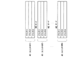
図5は磁気記録メディアに記録されるトラックの一単位の概念図である。 FIG. 5 is a conceptual diagram of one unit of a track recorded on the magnetic recording medium.
M個の記録ヘッドによって磁気記録メディアに記録されたM個のトラックをまとめた一単位を「ユニット」と呼ぶことにする。ここで、トラック(1)、トラック(2)、トラック(3)はそれぞれ、記録部100のM個の記録ヘッド151,152,153によって磁気記録メディアに記録されたトラックである。これらのトラック(1)、トラック(2)、トラック(3)のまとまりがユニット41である。それぞれのユニット41間、たとえば1番目のユニット(#1)と2番目のユニット(#2)との間にはガード42と呼ばれる、何も記録されていない領域が確保されている。このガード42の目的は、隣のユニットのトラックが再生されないようにすることにある。 A unit in which M tracks recorded on the magnetic recording medium by the M recording heads are referred to as a “unit”. Here, the track (1), the track (2), and the track (3) are tracks recorded on the magnetic recording medium by the M recording heads 151, 152, and 153 of the recording unit 100, respectively. A group of these tracks (1), tracks (2), and tracks (3) is a unit 41. Between each unit 41, for example, between the 1st unit (# 1) and the 2nd unit (# 2), the area | region which is called the guard 42 and nothing is recorded is ensured. The purpose of the guard 42 is to prevent the adjacent unit's track from being played.
図6は、磁気記録メディアに記録される分離パターンの例を示す図である。 FIG. 6 is a diagram illustrating an example of a separation pattern recorded on a magnetic recording medium.
同図に示すように、磁気記録メディアには、各再生ヘッド211,212,213によってそれぞれ複数のトラックに跨って再生された信号からトラックごとの信号を分離するために必要なパターンとして、先頭より、第1のプリアンブル51、SYNC52、第2のプリアンブル53が順に記録されている。第2のプリアンブル53の後にはデータ54が記録される。ここで、データ54は、記録時に図1の記録部100の記録符号化部121,122,123で作成された記録符号列である。第1のプリアンブル51、SYNC52、第2のプリアンブル53はプリアンブル付加部131,132,133によって付加されたものである。
As shown in the figure, the magnetic recording medium has a pattern necessary for separating a signal for each track from a signal reproduced across a plurality of tracks by the respective reproduction heads 211, 212, and 213, from the beginning.
再生時においては、第1のプリアンブル51は主に、図1の再生部200のAGC224,225,226による再生アンプ221,222,223のゲイン制御のための学習信号として使用される。また、第1のプリアンブル51は、必要に応じてビット同期検出の学習にも用いられる。SYNC52は前段の同期信号検出器231によって第2のプリアンブル53の開始位置を知るための同期信号として使用される。第2のプリアンブル53は信号分離処理部232にて、複数の再生ヘッドによってそれぞれ複数のトラックに跨って再生された信号からトラックごとの再生信号に分離するための信号処理で使用される。そしてデータ54はマルチトラック復調部240の各部において使用される。
During reproduction, the
第2のプリアンブル53では、トラックごとに所定の信号531,532,533が互いに物理的位置が重ならないように記録されている。すなわち、図6に示すように、トラック(1)のT1区間と、トラック(2)のT2区間と、トラック(3)のT3区間に、それぞれ所定の記録信号531,532,533が記録されている。これにより分離パターンの種類はトラック数に対応する3種類となる。また、この第2のプリアンブル53において、隣り合うトラックの各記録信号531,532,533の間には所定の時間の隙間Tgが設けられており、各トラックの各記録信号531,532,533が時間的に重ならないようにしてある。
In the
なお、分離パターンは、最小記録波長と同等か、あるいはそれ以上の所定の記録波長で記録される。 The separation pattern is recorded at a predetermined recording wavelength equal to or greater than the minimum recording wavelength.
信号分離処理部232は、この分離パターンの再生信号を用いてチャネル推定演算を行い、その結果として、後段でトラックごとの再生信号を分離するために必要となるチャネル推定情報を生成する。このチャネル推定情報は、複数のトラックをまとめた一単位であるユニットに対する個々の再生ヘッド211,212,213のトラック幅方向での位置情報に相当する。すなわち、チャネル推定情報は、個々の再生ヘッド211,212,213がそれぞれ、ユニット内のどのトラックとどんな割合で位置的に重なるかを示した情報である。
The signal
さらに、信号分離処理部232は、生成されたチャネル推定情報と、再生ヘッド211,212,213によって再生された再生信号とから所定の信号分離演算を行うことによって、各再生ヘッド211,212,213によりそれぞれ複数のトラックに跨って再生された信号からトラックごとの信号を分離する。
Further, the signal
なお、図6の例では、再生ヘッド211,212,213のヘッド幅Trは、記録トラック幅の1.5倍とされ、個々の再生ヘッド211,212,213で複数のトラックからの信号の再生が行われるようになっている。この場合には、再生ヘッド211は、トラック(1)とトラック(2)とに跨って信号を再生し、再生ヘッド212は、3本のトラック(1)(2)(3)に跨って信号を再生し、再生ヘッド213はトラック(2)とトラック(3)とに跨って信号を再生する。
In the example of FIG. 6, the head width Tr of the reproducing
したがって、信号分離処理によって、トラック(1)の信号は再生ヘッド211からの信号と再生ヘッド212からの信号で生成される。トラック(2)の信号は再生ヘッド211、再生ヘッド212、そして再生ヘッド213からの信号で生成される。トラック(3)の信号は再生ヘッド212からの信号と再生ヘッド213からの信号で生成される。
Therefore, the signal of the track (1) is generated by the signal from the reproducing
ここで、特にトラック(2)は、トラック位置のずれた3箇所から再生された3つの再生信号を用いて、一つのトラックの信号を取り出すことができる。したがって、従来の記録再生装置のように一つのトラックを一つの再生ヘッドで一度だけ再生した場合と比較して、良好な再生が保証されるトラックに対する再生ヘッドの位置ずれ量を増大させることができる。 Here, in particular, for the track (2), the signal of one track can be extracted by using three reproduction signals reproduced from three positions whose track positions are shifted. Therefore, as compared with the case where one track is reproduced only once by one reproducing head as in the conventional recording / reproducing apparatus, it is possible to increase the positional deviation amount of the reproducing head with respect to the track for which good reproduction is guaranteed. .
なお、図5に示したユニット41の例では、ユニット41間に配置されたガード42によって、隣のユニット41のトラックから信号が再生されるのを防止するようにしたが、ガード42を配置しない、つまり各ユニットをトラック幅方向において詰めて配置するようにしてもよい。 In the example of the unit 41 shown in FIG. 5, the guard 42 disposed between the units 41 prevents the signal from being reproduced from the track of the adjacent unit 41, but the guard 42 is not disposed. In other words, each unit may be arranged in the track width direction.
隣のユニットのトラックから信号が再生されないようにする他の方法としては、ユニットの外側(両端)のトラックの幅が他のトラックよりも大きくなるように各記録ヘッドの幅を設定し、再生ヘッドの幅を外側のトラックに対応する記録ヘッドの幅よりも小さく設定する方法や、トラックの幅はすべて同一とし、ユニットの外側のトラックに対応する再生ヘッドの幅を他の再生ヘッドの幅よりも小さく設定する方法、などがある。 As another method for preventing the signal from being reproduced from the track of the adjacent unit, the width of each recording head is set so that the width of the track on the outside (both ends) of the unit is larger than that of the other track, and the reproduction head The width of the recording head is set to be smaller than the width of the recording head corresponding to the outer track, or the width of the track is the same, and the width of the reproducing head corresponding to the outer track of the unit is set to be wider than the width of the other reproducing heads There is a method to set it small.
また、ユニットに対する各再生ヘッドの位置情報を得るには、上記のような分離パターンによらず、トラッキングサーボ情報を用いることも可能である。この場合には、トラッキングサーボ情報により、ユニット内の各記録パターンと各再生ヘッドとの位置関係が与えられる。これらの位置関係をユニット単位にまとめたものがチャネル推定情報として生成される。以下同様に、生成されたチャネル推定情報と、各再生ヘッドによって再生された信号とから、所定の信号分離演算によってトラックごとの信号を分離することが行われる。 Further, in order to obtain the position information of each reproducing head with respect to the unit, it is also possible to use tracking servo information regardless of the separation pattern as described above. In this case, the positional relationship between each recording pattern in the unit and each reproducing head is given by the tracking servo information. A summary of these positional relationships in units is generated as channel estimation information. Similarly, the signal for each track is separated from the generated channel estimation information and the signal reproduced by each reproducing head by a predetermined signal separation operation.
なお、分離パターンを用いて各再生ヘッドの位置情報を得る手段と、トラッキングサーボ情報を用いて再生ヘッドの位置情報を得る手段は、その一方のみならず、両方を併用してもよい。 Note that the means for obtaining the position information of each reproducing head using the separation pattern and the means for obtaining the position information of the reproducing head using the tracking servo information may be used in combination of both.
図7は、変形例として、記録ヘッドの数を3とし、再生ヘッドの数を4とした場合の例である。 FIG. 7 shows an example in which the number of recording heads is 3 and the number of reproducing heads is 4 as a modification.
再生ヘッド211,212,213,214のヘッド幅Trは、図示しない記録ヘッドの幅以上とする。再生ヘッド211は、トラック(1)とトラック(2)とに跨って信号を再生し、再生ヘッド212はトラック(1)とトラック(2)に跨って信号を再生し、再生ヘッド213は、トラック(2)とトラック(3)に跨って信号を再生し、再生ヘッド214もトラック(2)とトラック(3)とに跨って信号を再生する。
The head width Tr of the reproducing
この場合、信号分離処理によって、トラック(1)の信号は再生ヘッド211と再生ヘッド212からの信号で生成される。トラック(2)の信号は再生ヘッド211、再生ヘッド212、再生ヘッド213、再生ヘッド214からの信号で生成される。トラック(3)の信号は再生ヘッド213と再生ヘッド214からの信号で生成される。
In this case, the signal of the track (1) is generated by signals from the reproducing
ここで、特にトラック(2)の信号は、トラック位置のずれた4箇所から再生された4つの再生信号を用いて、一つのトラックからの信号を取り出すことができる。したがって、従来の記録再生装置のように、一つのトラックを一つの再生ヘッドで一度だけ再生した場合と比較して、良好な再生が保証されるトラックに対する再生ヘッドの位置ずれ量を増大させることができる。 Here, in particular, for the signal of the track (2), the signal from one track can be extracted by using the four reproduced signals reproduced from the four positions shifted in the track position. Therefore, as compared with the case where one track is reproduced only once by one reproducing head as in the conventional recording / reproducing apparatus, the positional deviation amount of the reproducing head with respect to the track for which good reproduction is guaranteed can be increased. it can.
また、この例においても、たとえば、図5に示したように、ユニット間にガード42を配置するなど、隣のユニットのトラックから信号を再生しないような手段が採用されている。 Also in this example, as shown in FIG. 5, for example, a means that does not reproduce a signal from a track of an adjacent unit is employed, such as arranging a guard 42 between units.
このように記録ヘッドの数よりも再生ヘッドの数を多くした構成においても、信号分離処理部232にて、同様に、分離パターンの再生信号を用いてチャネル推定情報を生成し、このチャネル推定情報と、各再生ヘッド211,212,213,214によって読み込まれたデータ情報とから所定の信号分離演算を行うことによって、各再生ヘッド211,212,213,214により再生された、複数のトラックに跨った信号からトラックごとの信号を分離することができる。
Even in the configuration in which the number of reproducing heads is larger than the number of recording heads in this way, the signal
次に、信号分離処理部232によるチャネル推定演算及び信号分離演算の具体例を説明する。
Next, a specific example of channel estimation calculation and signal separation calculation by the signal
所定のサンプル位置kにおける、各記録ヘッドによって記録された元のデータベクトルを、 The original data vector recorded by each recording head at a predetermined sample position k,

従って、式(3)の左から行列の一般化逆行列を掛けることで、 Therefore, by multiplying the generalized inverse matrix of the matrix from the left of equation (3),
すなわち、信号分離処理部232は、チャネル推定演算として式(3)の行列Hの演算を行い、次いで、信号分離演算として、行列の一般化逆行列(行列が平方行列であり、さらに正則であれば単に逆行列と言ってもよい。)の演算と、式(4)の演算を行う。これにより、各再生ヘッドによってそれぞれ複数のトラックに跨って再生された各信号から、トラックごとの再生信号が得られる。
That is, the signal
行列Hは、ユニットのトラック数と、それに対応する再生信号の数で決まる。図6の例では、ユニットのトラック数(記録ヘッド数)が3であり、再生信号数(再生ヘッド数)が3である。よって、行列Hは、次の式(5)の通り、3行3列の行列で表される。 The matrix H is determined by the number of tracks of the unit and the number of reproduction signals corresponding thereto. In the example of FIG. 6, the number of tracks (number of recording heads) of the unit is 3, and the number of reproduction signals (number of reproduction heads) is 3. Therefore, the matrix H is represented by a matrix of 3 rows and 3 columns as in the following formula (5).
また、図7の例では、ユニットのトラック数(記録ヘッド数)が3であり、再生信号数(再生ヘッド数)が4である。このため行列Hは、次の式(6)の通り、4行3列の行列で表される。 In the example of FIG. 7, the number of tracks (number of recording heads) of the unit is 3, and the number of reproduction signals (number of reproduction heads) is 4. For this reason, the matrix H is expressed by a matrix of 4 rows and 3 columns as in the following Expression (6).
次に、チャネル推定情報としての行列Hの算出例について説明する。 Next, an example of calculating the matrix H as channel estimation information will be described.
行列の算出は、図6に示した第2のプリアンブル53の区間、すなわち、トラックごとにT1区間、T2区間、T3区間の期間で行われる。式(3)において、T1区間をk=t1、T2区間をk=t2、そしてT3区間をk=t3とする。またデータベクトルは、図5の各トラックの分離パターンを同一とし、さらに簡単にすると、以下のように表すことができる。
The matrix is calculated in the
T1区間では、k=t1において記録したデータベクトルは[1,0,0]であるから、 In T1, the data vector recorded at k = t1 is [1, 0, 0].
T2区間では、k=t2において記録したデータベクトルは[0,1,0]であるから、 In the T2 section, the data vector recorded at k = t2 is [0, 1, 0].
T3区間では、k=t3において記録したデータベクトルは[0,0,1]であるから、 In T3 section, the data vector recorded at k = t3 is [0, 0, 1].
式(8)、式(9)、そして式(10)より、すなわちk=t1、k=t2、そしてk=t3における再生信号によって、行列Hは次式(11)のように表すことができる。 From Expression (8), Expression (9), and Expression (10), that is, the reproduction signal at k = t1, k = t2, and k = t3, the matrix H can be expressed as the following Expression (11). .
以上のようにして、チャネル推定情報として行列が求められる。 As described above, a matrix is obtained as channel estimation information.
また、ここでは図6に基づいて式(5)の行列Hを算出し、さらにその一般化逆行列を求め、式(4)の演算を行うようにしたが、他の例として、図7をもとに式(6)の行列Hを用いた場合でも、同様にしてその一般化逆行列を求め、式(4)の演算を行うようにすればよい。 Further, here, the matrix H of the equation (5) is calculated based on FIG. 6, the generalized inverse matrix is obtained, and the calculation of the equation (4) is performed. As another example, FIG. Even when the matrix H of equation (6) is used, the generalized inverse matrix may be obtained in the same manner and the operation of equation (4) may be performed.
なお、図6及び図7の例において、分離パターンの種類はトラック数に対応させてある。これは、行列Hを算出した後、その一般化逆行列を求められるようにするためである。式(7)以外の分離パターンとしては、たとえば、式(12)などがある。この他、分離パターンには、互いに一次独立な3通りのパターンであればよい。 In the examples of FIGS. 6 and 7, the type of separation pattern corresponds to the number of tracks. This is because the generalized inverse matrix can be obtained after calculating the matrix H. As a separation pattern other than the expression (7), for example, there is an expression (12). In addition, the separation pattern may be three patterns that are primary and independent from each other.
ところで、上記の信号分離演算の方式では、式(11)の行列の一般化逆行列を求め、式(4)の演算を行っている。この式(4)を用いた方法は一般に、ゼロ・フォーシング(Zero Forcing)法と呼ばれる。なお、信号分離演算は、この式(4)を用いた方法に限定されるものではなく、たとえば、行列の一般化逆行列の代わりに、MMSE(Minimum Mean Squared Error)法を用いてもよい。このとき、式(4)は、 By the way, in the above signal separation calculation method, a generalized inverse matrix of the matrix of Expression (11) is obtained and the calculation of Expression (4) is performed. A method using this equation (4) is generally called a zero forcing method. The signal separation operation is not limited to the method using Equation (4), and for example, a MMSE (Minimum Mean Squared Error) method may be used instead of the generalized inverse matrix. At this time, the equation (4) becomes
以上により、本実施形態では、各再生ヘッドがそれぞれ複数のトラックに跨って再生した各信号をユニットの単位にまとめ、所定の信号処理を行うことで、トラックごとの再生信号を分離することができる。このため、ユニット内のトラック間の距離を、再生ヘッドの幅よりも小さく設定することができ、高トラック密度化を実現できる。 As described above, in the present embodiment, the signals reproduced by the reproducing heads over a plurality of tracks are collected in units of units, and predetermined signal processing can be performed to separate the reproduced signals for each track. . For this reason, the distance between the tracks in the unit can be set smaller than the width of the reproducing head, and a high track density can be realized.
ところで、図6にあるように、トラック数を3、再生ヘッド数を3とした場合で、図5に示したようにユニット41間にガード42が設けられている場合、再生ヘッド211が、ガード42、トラック(1)、トラック(2)に跨り、再生ヘッド212が、3本のトラック(1)(2)(3)に跨り、再生ヘッド213が、トラック(2)、トラック(3)、ガード42に跨る。
Incidentally, as shown in FIG. 6, when the number of tracks is 3 and the number of reproducing heads is 3, and the guard 42 is provided between the units 41 as shown in FIG. 42, straddling the track (1), the track (2), the reproducing
したがって、信号分離処理によって得られたトラックごとの信号について、トラック(1)の信号は再生ヘッド211からの信号と、再生ヘッド212からの信号で生成される。トラック(2)の信号は再生ヘッド211、再生ヘッド212、再生ヘッド213からの信号で生成される。そしてトラック(3)の信号は再生ヘッド212からの信号と、再生ヘッド213からの信号で生成される。
Therefore, for the signal for each track obtained by the signal separation processing, the signal of the track (1) is generated by the signal from the reproducing
ここで、たとえばトラック212の信号に注目した場合、トラック(2)の信号は、トラック位置のずれた3箇所から再生された3つの再生信号から生成されたものである。したがって、従来の磁気記録再生装置のように、一つのトラックを一つの再生ヘッドで一度だけ再生した場合と比較して、良好な信号再生が保証されるトラックに対する再生ヘッドの位置ずれ量を増大させることができる。
Here, for example, when attention is paid to the signal of the
また、図7に示したように、トラック数が3で、再生ヘッド数が4である場合には、再生ヘッド211が、ガード42、トラック(1)、トラック(2)に跨り、再生ヘッド212が、トラック(1)、トラック(2)、トラック(3)に跨り、再生ヘッド213が、トラック(1)、トラック(2)、トラック(3)に跨り、再生ヘッド214が、トラック(2)、トラック(3)、ガード42に跨る。
As shown in FIG. 7, when the number of tracks is 3 and the number of reproducing heads is 4, the reproducing
この場合には、信号分離処理によって得られたトラックごとの信号について、トラック(1)は再生ヘッド211、再生ヘッド212からの信号で生成される。トラック(2)は再生ヘッド211、再生ヘッド212、再生ヘッド213、再生ヘッド214からの信号で生成される。トラック(3)は再生ヘッド213、再生ヘッド214からの信号で生成される。
In this case, with respect to the signal for each track obtained by the signal separation processing, the track (1) is generated by signals from the reproducing
したがって、たとえばトラック(2)では、トラック位置のずれた4箇所から再生された、4つの再生信号を用いて、1つのトラック(2)信号を取り出すことができる。すなわち、従来の磁気記録再生装置における、所定のトラックを一つの再生ヘッドで一度だけ再生した場合と比較して、良好な信号再生が保証されるトラックに対する再生ヘッドの位置ずれ量を増大させることができる。 Therefore, for example, in the track (2), one track (2) signal can be extracted by using four reproduction signals reproduced from four positions shifted from each other in the track position. That is, the positional deviation amount of the reproducing head with respect to the track for which good signal reproduction is guaranteed can be increased as compared with the case where a predetermined track is reproduced only once by one reproducing head in the conventional magnetic recording / reproducing apparatus. it can.
次に、磁気記録メディア上で部分的に重ね合わせて記録される複数のトラック信号(いずれも単一波長)間の位相の関係について、図8及び図9を参照して説明する。 Next, a phase relationship between a plurality of track signals (all of which have a single wavelength) recorded on the magnetic recording medium in a partially overlapped manner will be described with reference to FIGS.
図8において、再生ヘッドアレイ210の再生ヘッド211は、トラック(1)とその上に一部の幅を重ねて記録されたトラック(2)とから信号を再生する。ここで、両トラック信号(1)(2)の位相関係が、図8(a)のように同一位相であるならば、再生ヘッド211によって再生される信号は、両トラック信号(1)(2)が足し合わされた結果、図9(a)に示すように最大振幅で再生される。また、図8(b)のように両トラック信号(1)(2)の位相が180度ずれている場合には、再生ヘッド211によって再生される信号の最大振幅は、両トラック信号(1)(2)が足し合わされた結果、図9(b)に示すように減少する。
この位相ずれによる再生出力の低下は、図1のAGC224,225,226のゲインを設定するために用いられる図6の51の第1のプリアンブルで影響を及ぼす。位相がずれていると位相が揃った状態と比較して、AGCのゲインが大きく設定されてしまう。すると、後の処理において、動作範囲を確保できなくなる恐れがある。したがって、隣接トラック間では、記録信号の位相を一定以内に収める必要がある。
In FIG. 8, the reproducing
The reduction in reproduction output due to this phase shift affects the
そこで、本実施形態では、隣接する各トラック信号の位相ずれが一定範囲内に収まるように、記録部100の出力タイミング設定部141,142,143によるトラックごとの記録信号の出力タイミングを制御することが行われる。この隣接する各トラック信号の位相合わせは、ユーザデータを実際に記録する直前、あるいは、必要精度によっては、工場出荷時に行われる。
Therefore, in the present embodiment, the output timing of the recording signal for each track is controlled by the output
図10は、隣接トラックの信号の位相合わせに関するブロック図である。同図は、隣接する記録ヘッド151と記録ヘッド152によって記録されるトラック信号の位相合わせに関する構成のみを示している。位相制御信号発生器90は、再生部200のAGC224内のレベル検出器93の出力を受けて、記録ヘッド152に与える記録信号の出力タイミングを設定する出力タイミング設定部142に制御信号を与える。ここで、出力タイミング設定部142は具体的には遅延素子で構成され、位相制御信号発生器90より与えられた遅延量を設定する。
FIG. 10 is a block diagram relating to phase alignment of signals of adjacent tracks. This figure shows only the configuration relating to the phase alignment of track signals recorded by the
上のような構成を用いて、隣接トラック間の位相ずれをπ/36[rad]以内までに収めることを目標とする例を説明する。ただし、実際のシステムに適用する場合には、そのシステムに必要な精度があるはずであるから、それに従って目標が設定されるべきである。 An example in which the phase shift between adjacent tracks is set within π / 36 [rad] using the above configuration will be described. However, when applied to an actual system, the system should have the required accuracy, and the target should be set accordingly.
図11および図12は、上記の隣接トラック信号の位相合わせに関するフローチャートである。 11 and 12 are flowcharts relating to the phase alignment of the adjacent track signal.
図10において、記録ヘッド151により記録されるトラック信号(ch1)と記録ヘッド152により記録されるトラック信号(ch2)の位相を揃える(ステップS1001)。
In FIG. 10, the phases of the track signal (ch1) recorded by the
まず、学習用記録信号81が記録補償器144で記録補償される(ステップS1002)。次に学習用記録信号82が出力タイミング決定部142にて初期遅延量だけ遅延され記録補償器145で記録補償される(ステップS1003)。次に144、145で記録補償されたそれぞれの信号が記録ヘッド151、152に出力され、2本の隣接するトラック信号(ch1とch2)が記録される(ステップS1004)。学習用記録信号81及び学習用記録信号82は、同一の信号であって、単一周波数の繰り返し信号である。
First, the
次に、磁気記録メディア2から、再生ヘッド211によってトラック信号(ch1)と(ch2)を跨った状態での再生を行う(ステップS1005)。再生ヘッド211によって再生された信号は再生アンプ221によって適当な電圧まで増幅され(ステップS1006)、AGC224内のレベル検出器93にて信号レベルの計測が行われる(ステップS1007)。計測された信号レベルは位相制御信号発生器90へ送られ、Level_0として保持される(ステップS1008)。
Next, reproduction is performed from the
続いて、位相制御信号発生器90は、学習用記録信号82の位相をπ/6進めるように制御信号を出力タイミング設定部142に与える(ステップS1009)。出力タイミング設定部142は、制御信号を受けて位相をπ/6進めるように遅延量の設定を行う(ステップS1010)。これにより、学習用記録信号82は出力タイミング設定部142にて位相がπ/6だけ進むように遅延され、記録補償器145にて記録補償がなされる(ステップS1011)。記録補償部144及び145で記録補償された信号が記録ヘッド151,152に出力され、ch1とch2が再度記録される(ステップS1012)。
Subsequently, the phase
次に、再度再生ヘッド211によってトラック信号(ch1)と(ch2)を跨った状態にて再生を行い(ステップS1013)、再生ヘッド211によって再生された信号は再生アンプ221によって適当な電圧まで増幅され(ステップS1014)、AGC224内のレベル検出器93にて、その信号レベルの計測を行う(ステップS1015)。計測された信号レベルは位相制御信号発生器90へ送られ、Level_1として保持される(ステップS1016)。続いて、位相制御信号発生器90は、Level_0の値とLevel_1の値とを比較する(ステップS1017)。この比較で、Level_1の値がLevel_0の値以上である場合には(ステップS1017のYES)、位相制御信号発生器90は、Level_1の値を新たなLevel_0の値として更新した後(ステップS1018)、ステップS1009からS1017までが繰り返される。
Next, reproduction is performed again with the
Level_1の値がLevel_0の値未満である場合には(ステップS1017のNO)、位相制御信号発生器90は、位相をπ/18だけ遅らすよう制御信号を出力タイミング設定部142に与える(ステップS1019)。この結果、出力タイミング設定部142は制御信号を受けて位相をπ/18遅らす様に遅延量の設定を行い(ステップS1020)学習用記録信号82は、出力タイミング設定部142にて位相がπ/18だけ遅れるように遅延され、記録補償器145にて記録補償がなされる(ステップS1021)。次に記録補償器144、145で記録補償された信号が、記録ヘッド151、152にそれぞれ出力され、ch1とch2が再度記録される(ステップS1022)。この後、再生ヘッド211にてトラック信号(ch1)と(ch2)を跨った状態での再生が再度行われ(ステップS1023)、再生ヘッド211によって再生された信号は再生アンプ221によって適当な電圧まで増幅され(ステップS1024)、AGC224内のレベル検出器93にて、その信号レベルの計測が行われる(ステップS1025)。計測された信号レベルは位相制御信号発生器90へ送られ、新たなLevel_1の値として保持される(ステップS1026)。
When the value of Level_1 is less than the value of Level_0 (NO in step S1017), the phase
次に、位相制御信号発生器90は、Level_0の値とLevel_1の値とを比較する(ステップS1027)。この比較で、Level_1の値がLevel_0の値以上である場合には(ステップS1027のYES)、Level_1の値を新たなLevel_0の値として更新した後(ステップS1028)、ステップS1019からS1027までが繰り返される。
Next, the phase
Level_1の値がLevel_0の値未満である場合には(ステップS1027のNO)、位相制御信号発生器90は、学習用記録信号82の位相をπ/36だけ進ませるように制御信号を出力タイミング設定部142に与える(ステップS1029)。出力タイミング設定部142は、制御信号を受けて位相をπ/36だけ進ませるように遅延量の設定を行う(ステップS1030)。学習用記録信号82は出力タイミング設定部142にて位相がπ/36だけ進むように遅延され、記録補償器145にて記録補償がなされる(ステップS1031)。記録補償器144,145で記録補償された信号が、記録ヘッド151、152にそれぞれ出力され、ch1とch2が再度記録される。(ステップS1032)。この後、再生ヘッド211にてトラック信号(ch1)と(ch2)を跨った状態での再生が行われ(ステップS1033)、再生ヘッド211によって再生された信号は再生アンプ221によって適当な電圧まで増幅される(ステップ1034)。再生アンプ211によって増幅された信号はAGC224内のレベル検出器93にてレベル検出が行われる(ステップS1035)。レベル検出器93により計測された信号レベルは位相制御信号発生器90へ送られ、新たなLevel_1の値として保持される。
When the value of Level_1 is less than the value of Level_0 (NO in step S1027), the phase
次に、位相制御信号発生器90は、Level_0の値とLevel_1の値とを比較する(ステップS1037)。この比較で、Level_1の値がLevel_0の値以上である場合には(ステップS1037のYES)、Level_1の値を新たなLevel_0の値として更新した後(ステップS1038)、ステップS1029からステップS1037までが繰り返される。
Next, the phase
Level_1がLevel_0未満である場合には(ステップS1037のNO)、記録信号の位相合わせを終了とする(ステップS1039)。 If Level_1 is less than Level_0 (NO in step S1037), the phase alignment of the recording signals is terminated (step S1039).
この後は、引き続きトラック信号(ch2)とトラック信号(ch3)について、上記と同様の手順を行うことによって、位相ずれがπ/36[rad]以内となるように位相合わせを行う。トラック数が3である場合は、ここまでで一連の位相合わせの処理は終了となる。トラック数が3よりも大きい場合でも、同様の手順で、隣接トラック信号の位相合わせを行うことができる。 Thereafter, the phase alignment is performed so that the phase shift is within π / 36 [rad] by performing the same procedure as described above for the track signal (ch2) and the track signal (ch3). When the number of tracks is 3, a series of phase matching processes is completed so far. Even when the number of tracks is larger than 3, the phase of adjacent track signals can be adjusted in the same procedure.
以上のように、本実施形態では、第1段階で荒い精度(π/6)で位相合わせを行い、その後、徐々に第2、第3段階で、より厳密な精度(π/18、π/36)にて位相合わせを行うことによって、最終的に各トラック信号の位相ずれを目標精度までに収めることができる。 As described above, in the present embodiment, phase alignment is performed with coarse accuracy (π / 6) in the first stage, and then gradually more precise accuracy (π / 18, π /) is gradually obtained in the second and third stages. By performing phase matching in 36), the phase shift of each track signal can be finally brought to the target accuracy.
次に、上記の隣接トラック信号の位相合わせに関する処理の変形例を説明する。図13および図14は、この隣接トラック信号の位相合わせに関する処理の変形例を示すフローチャートである。 Next, a modified example of the processing related to the phase adjustment of the adjacent track signal will be described. FIG. 13 and FIG. 14 are flowcharts showing modified examples of processing relating to the phase adjustment of the adjacent track signals.
図10において、記録ヘッド151により記録されるトラック信号(ch1)と記録ヘッド152により記録されるトラック信号(ch2)の位相を揃える(ステップS3001)。
In FIG. 10, the phases of the track signal (ch1) recorded by the
まず、学習記録信号81が記録補償期144で記録補償される(ステップS3002)。次に学習用記録信号82が出力タイミング決定部142にて初期遅延量だけ遅延され、記録補償器145で記録補償される(ステップS3003)。そして記録補償器144、145で記録補償された信号が記録ヘッド151、152に出力され、これによって磁気記録メディア2に2本の隣接するトラック信号(ch1,ch2)の記録を行う(ステップS3004)。学習用記録信号81及び学習用記録信号82は、同一の信号であって、単一周波数の繰り返し信号である。
First, the learning
次に、磁気記録メディア2から、再生ヘッド211によってトラック信号(ch1)と(ch2)を跨った状態での再生を行う(ステップS3005)。再生ヘッド211によって再生された信号は再生アンプ221によって適当な電圧まで増幅され(ステップ3006)、AGC224内のレベル検出器93にて信号レベルの計測が行われる(ステップS3007)。計測された信号レベルは位相制御信号発生器90へ送られ、Level_0として保持される(ステップS3008)。
Next, reproduction from the
続いて、位相制御信号発生器90は、学習用記録信号82の位相をπ/6進めるように制御信号を出力タイミング設定部142に与える(ステップS3009)。出力タイミング設定部142は、制御信号を受けて位相をπ/6進めるように遅延量の設定を行う(ステップS3010)。これにより、学習用記録信号82は出力タイミング設定部142にて位相がπ/6だけ進むように遅延され、記録補償器145にて記録補償がなされる(ステップS3011)。記録補償器145で記録補償された信号が記録ヘッド152に出力され、磁気記録メディア2にトラック信号(ch2)として再度記録される(ステップS3012)。このとき、図11および図12の処理例で行われていた記録ヘッド151によるトラック信号(ch1)の記録は行われない。
Subsequently, the phase
次に、再度再生ヘッド211によってトラック信号(ch1)と(ch2)を跨った状態にて再生を行い(ステップS3013)、再生ヘッド211によって再生された信号は、再生アンプ221によって適当な電圧まで増幅される(S3014)。再生アンプ211によって増幅された信号は、AGC224内のレベル検出器93にて、その信号レベルの計測を行う(ステップS3015)。計測された信号レベルは位相制御信号発生器90へ送られ、Level_1として保持される(ステップS3016)。続いて、位相制御信号発生器90は、Level_0の値とLevel_1の値とを比較する(ステップS3017)。この比較で、Level_1の値がLevel_0の値以上である場合には(ステップS3017のYES)、位相制御信号発生器90は、Level_1の値を新たなLevel_0の値として更新した後(ステップS3018)、ステップS3009からS3017が繰り返される。
Next, reproduction is performed again with the
Level_1の値がLevel_0の値未満である場合には(ステップS3017のNO)、位相制御信号発生器90は、位相をπ/18だけ遅らすよう制御信号を出力タイミング設定部142に与える(ステップS3019)。出力タイミング設定部142は制御信号を受けて位相をπ/18遅らすように遅延量の設定を行う(ステップS3020)。この結果、学習用記録信号82は出力タイミング設定部142にて位相をπ/18だけ遅らすように遅延され、記録補償器145にて記録補償がなされる(ステップS3021)。記録補償器145で記録補償された信号が、記録ヘッド152に出力され、磁気記録メディア2にトラック信号(ch2)として再度記録される(ステップS3022)。この後、再生ヘッド211にてトラック信号(ch1)と(ch2)を跨った状態での再生が再度行われ(ステップS3023)、再生ヘッド211によって再生された信号は再生アンプ221によって適当な電圧まで増幅される(ステップS3024)。再生アンプ221によって増幅された信号はAGC224内のレベル検出器93にて、その信号レベルの計測が行われる(ステップS3025)。計測された信号レベルは位相制御信号発生器90へ送られ、新たなLevel_1の値として保持される(ステップS3026)。
When the value of Level_1 is less than the value of Level_0 (NO in step S3017), the phase
次に、位相制御信号発生器90は、Level_0の値とLevel_1の値とを比較する(ステップS3027)。この比較で、Level_1の値がLevel_0の値以上である場合には(ステップS3027のYES)、Level_1の値を新たなLevel_0の値として更新した後(ステップS3028)、ステップS3019からS3027までが繰り返される。
Next, the phase
Level_1の値がLevel_0の値未満である場合には(ステップS3027のNO)、位相制御信号発生器90は、学習用記録信号82の位相をπ/36だけ進ませるように制御信号を出力タイミング設定部142に与える(ステップS3029)。出力タイミング設定部142は制御信号を受けて位相をπ/36進ませるように遅延量の設定を行う(ステップS3030)。学習用記録信号82は出力タイミング設定部142にて位相がπ/36だけ進むように遅延され、記録補償器145にて記録補償がなされる(ステップS3031)。記録補償器145で記録補償された信号が記録ヘッド152に出力され、磁気記録メディア2にトラック信号(ch2)として再度記録される(ステップS3032)。この後、再生ヘッド211にてトラック信号(ch1)と(ch2)を跨った状態での再生が行われ(ステップS3033)、再生ヘッド211によって再生された信号は再生アンプ221によって適当な電圧まで増幅される(ステップS3034)。再生アンプ221によって増幅された信号はAGC224内のレベル検出器93にて、その信号レベルの計測が行われる(ステップS3035)。計測された信号レベルは位相制御信号発生器90へ送られ、新たなLevel_1の値として保持される(ステップS3036)。
When the value of Level_1 is less than the value of Level_0 (NO in step S3027), the phase
次に、位相制御信号発生器90は、Level_0の値とLevel_1の値とを比較する(ステップS3037)。この比較で、Level_1の値がLevel_0の値以上である場合には(ステップS3037のYES)、Level_1の値を新たなLevel_0の値として更新した後(ステップS3038)、ステップS3029からS3037までが繰り返される。
Next, the phase
Level_1がLevel_0未満である場合には(ステップS3037のNO)、記録信号の位相合わせを終了とする(ステップS3039)。 If Level_1 is less than Level_0 (NO in step S3037), the phase alignment of the recording signals is terminated (step S3039).
この後は、引き続きトラック信号(ch2)とトラック信号(ch3)について、上記と同様の手順を行うことによって、位相ずれがπ/36[rad]以内となるように位相合わせを行う。トラック数が3である場合は、ここまでで一連の位相合わせの処理は終了となる。トラック数が3よりも大きい場合でも、同様の手順で、隣接トラック信号の位相合わせを行うことができる。 Thereafter, the phase alignment is performed so that the phase shift is within π / 36 [rad] by performing the same procedure as described above for the track signal (ch2) and the track signal (ch3). When the number of tracks is 3, a series of phase matching processes is completed so far. Even when the number of tracks is larger than 3, the phase of adjacent track signals can be adjusted in the same procedure.
以上のように、本実施形態では、第1段階で荒い精度(π/6)で位相合わせを行い、その後、徐々に第2、第3段階で、より厳密な精度(π/18、π/36)にて位相合わせを行うことによって、最終的に各トラック信号の位相ずれを目標精度のπ/36までに収めることができる。 As described above, in the present embodiment, phase alignment is performed with coarse accuracy (π / 6) in the first stage, and then gradually more precise accuracy (π / 18, π /) is gradually obtained in the second and third stages. By performing the phase alignment in 36), the phase shift of each track signal can be finally brought to the target accuracy of π / 36.
次に、隣接トラック信号の位相合わせを行うために、公知の"最急降下法"と呼ばれている方法を適用した場合について説明する。 Next, a case where a known method called “steepest descent method” is applied to perform phase alignment of adjacent track signals will be described.
ここでは具体例として、隣接トラック間の位相ずれを"π/36[rad]以内"までに収めることを目標とする例を説明する。ただし、実際のシステムに適用する場合には、そのシステムに必要な精度があるはずであるから、それに従って目標設定されるべきである。 Here, as a specific example, an example in which the phase shift between adjacent tracks is set to be within “π / 36 [rad]” will be described. However, when applied to an actual system, the system should have the required accuracy and should be set accordingly.
図15は、この別の方法による、隣接トラック信号の位相合わせに関するフローチャートである。 FIG. 15 is a flowchart regarding phase alignment of adjacent track signals according to this different method.
先の説明と同様に、図10において、記録ヘッド151により記録されるトラック信号(ch1)と記録ヘッド152により記録されるトラック信号(ch2)の位相を揃える(ステップS1101)。
As in the previous description, in FIG. 10, the phase of the track signal (ch1) recorded by the
まず、学習用記録信号81が記録補償器144で記録補償される(ステップS1102)。次に学習用記録信号82が出力タイミング決定部142にて初期遅延量だけ遅延され、記録補償器145で記録補償される(ステップS1103)。記録補償器144、145で記録補償された信号が、記録ヘッド151、152に出力され、磁気記録メディア2に2本の隣接するトラック信号(ch1,ch2)の記録を行う(ステップS1104)。学習用記録信号81及び学習用記録信号82は、同一の信号であって、単一周波数の繰り返し信号である。
First, the
次に、磁気記録メディア2から、再生ヘッド211によってトラック信号(ch1)と(ch2)を跨った状態での再生を行う(ステップS1105)。再生ヘッド211によって再生された信号は再生アンプ221によって適当な電圧まで増幅され(ステップS1106)、AGC224内のレベル検出器93にて信号レベルの計測が行われる(ステップS1107)。計測された信号レベルは位相制御信号発生器90へ送られ、Level_0として保持される(ステップS1108)。
Next, reproduction is performed from the
次に、位相制御信号発生器90は、トラック信号(ch2)の位相を、最終目標の分解能であるπ/36(=minΔx)だけ進めるように制御信号を出力タイミング設定部142に与える(ステップS1109)。これにより、学習用記録信号82は出力タイミング設定部142にて位相がπ/36だけ進むように遅延量が設定され(ステップS1110)、記録補償器145にて記録補償がなされ(ステップS1111)、記録ヘッド152に送られ、磁気記録メディア2にトラック信号(ch2)として、記録ヘッド151によるトラック信号(ch1)の記録と同時に再度記録される(ステップS1112)。
Next, the phase
次に、再度再生ヘッド211にてトラック信号(ch1)と(ch2)を跨った状態での再生を行い(ステップS1113)、再生ヘッド211によって再生された信号は再生アンプ221によって適当な電圧まで増幅され(ステップS1114)、AGC224内のレベル検出器93にて、その信号レベルの計測を行う(ステップS1115)。計測された信号レベルは位相制御信号発生器90へ送られ、Level_1の値として保持される(ステップS1116)。
Next, the
ここで、位相制御信号発生器90は、下記の式(14)を計算する(ステップS1117)。
Here, the phase
次に、位相制御信号発生器90は、この計算で求めたαを勾配として考え、次にxの変化量Δxを下記の式(15)により計算する(ステップS1118)。
Next, the phase
ここで、μは更新係数であり、0<μ<1の範囲で適切に定められた定数とする。 Here, μ is an update coefficient, and is a constant appropriately determined in the range of 0 <μ <1.
この結果、 As a result,
引き続きトラック信号(ch2)とトラック信号(ch3)について、上記と同様の手順で処理を行うことによって、位相ずれがπ/36[rad]以内となるように位相合わせを行う。トラック数が3である場合は、ここまでで一連の記録信号位相合わせの処理は終了となる。トラック数が3よりも大きい場合でも、同様の手順で、隣接トラック信号の位相合わせを行うことができる。 Subsequently, the track signal (ch2) and the track signal (ch3) are processed in the same procedure as described above, so that the phase is adjusted so that the phase shift is within π / 36 [rad]. When the number of tracks is 3, a series of recording signal phase matching processes is completed so far. Even when the number of tracks is larger than 3, the phase of adjacent track signals can be adjusted in the same procedure.
もし式(16)が成立しなかった場合、遅延量xを下記の式(17)により更新する(ステップS1121)。 If the equation (16) is not satisfied, the delay amount x is updated by the following equation (17) (step S1121).
この後、ステップS1103に戻り、学習用記録信号82は更新された遅延量xで遅延され、記録ヘッド151によって磁気記録メディア2にトラック信号(ch2)として再度記録される。そして、ステップS1108で、式(16)の条件が成立するまで、以上の処理が繰り返される。
Thereafter, the process returns to step S1103, and the learning
なお、以上説明した隣接トラック信号の位相合わせでは、学習用記録信号はできるだけ正弦波に近い再生信号が得られるような記録波長であることが前提になっている。つまり、再生信号が孤立波形状になるような長波長の記録信号ではなく、正弦波に近い再生信号が得られる短波長の記録信号を使う必要がある。 Note that the phase adjustment of the adjacent track signals described above is based on the premise that the learning recording signal has a recording wavelength at which a reproduction signal as close to a sine wave as possible can be obtained. That is, it is necessary to use a short-wavelength recording signal from which a reproduction signal close to a sine wave can be obtained, not a long-wavelength recording signal in which the reproduction signal has a solitary wave shape.
(第2の実施形態)
次に、本発明の第2の実施形態として、シングルヘッドおよびマルチトラックを用いた磁気記録再生装置について図16乃至図19を用いて説明する。
(Second Embodiment)
Next, as a second embodiment of the present invention, a magnetic recording / reproducing apparatus using a single head and a multitrack will be described with reference to FIGS.
図16は、本実施形態にかかる磁気記録再生装置の構成を示す図である。この磁気記録再生装置は、記録部300と再生部400を備える。 FIG. 16 is a diagram showing the configuration of the magnetic recording / reproducing apparatus according to the present embodiment. This magnetic recording / reproducing apparatus includes a recording unit 300 and a reproducing unit 400.
記録部300では、マルチトラック分離パターン付加部130の複数のプリアンブル付加部131,132,133と出力タイミング設定部141との間に、少なくとも1ユニット分の記録データを記憶する記憶部134が配置される。記憶部134には、ユニットを構成するトラックごとの、分離パターンを含む記録符号列が記憶される。
In the recording unit 300, a
この再生部400は、前段の同期信号検出器231と信号分離処理部232との間に少なくとも1ユニット分の再生信号を記憶する記憶部233が配置される。再生ヘッド211はユニットに対する最初の位置(たとえば図17のP4の位置)で複数のトラック(T1,T2)からの信号の再生を行い、次にP5の位置に移動して複数のトラック(T2、T3)からの信号の再生を行い、さらにP6の位置に移動して、図17の例ではトラックT3以降に記録されたトラックが無いため、トラックT3からの信号の再生を行う。なお、シングルヘッドによる再生時の記録トラックのトレースは、少なくとも1ユニットの記録トラック数の回数繰り返される。すなわち、記録トラック数以上の回数トレースを繰り返してもよい。その際、1ユニット分の全ての記録トラックが少なくとも1回はトレースされるようにする。記憶部233には、再生ヘッド211が移動した各位置で再生した1ユニット分の信号、すなわち再生ヘッド211が各位置で複数のトラックからそれぞれ再生した信号であり、前段の同期信号検出器231によって分離パターン以降の再生信号が記憶される。
In the reproduction unit 400, a
そして、記録部300と再生部400とを連結する要素として、磁気記録メディア2に記録される複数のトラックの中の隣接するトラックの記録信号の位相を合わせるための制御を行う手段として位相制御信号発生器90が設けられている。
Then, as an element for connecting the recording unit 300 and the reproducing unit 400, a phase control signal is used as a means for performing control for matching the phases of the recording signals of adjacent tracks among the plurality of tracks recorded on the
次に、この実施形態の磁気記録再生装置の基本的な記録と再生の動作について説明する。 Next, basic recording and reproducing operations of the magnetic recording / reproducing apparatus of this embodiment will be described.
まず、記録の動作から説明する。図18は記録の動作に関するフローチャートである。 First, the recording operation will be described. FIG. 18 is a flowchart regarding the recording operation.
この記録部300では、まず、入力された記録データ1がマルチトラック化部110にて、トラックごとのデータに分配される(ステップS1501)。次に、分配された各データは、それぞれマルチトラック記録符号化部120の記録符号化部121,122,123にて、磁気記録メディア2の記録再生特性を考慮した符号語列に符号化される。このとき符号語列に、同期信号など復号時に必要な情報も付加される(ステップS1502)。
In the recording unit 300, first, the
次に、生成されたトラックごとの符号語列の所定の位置に対して、マルチトラック分離パターン付加部130のプリアンブル付加部131,132,133にてプリアンブル符号が与えられて記録符号列が得られる(ステップS1503)。このようにして生成されたトラックごとの記録符号列は記憶部134に記憶される(ステップS1504)。
Next, a preamble code is given to the predetermined position of the generated code word string for each track by the
次に、記憶部134から、最初に記録するトラックの記録符号列が読み出され(ステップS1505)、このトラックの記録符号列は出力タイミング設定部141によって所望のタイミングが与えられた後、記録補償部144にて、磁気記録メディア2への記録に最適化するための記録補償処理が施され、記録アンプ147にて電圧から電流に変換されて記録ヘッド151に送られ、記録ヘッド151によって磁気記録メディア2に記録される(ステップS1506)。
Next, the recording code string of the track to be recorded first is read from the storage unit 134 (step S1505), and the recording code string of this track is given a desired timing by the output
1つのトラックの記録が終了した後、1ユニット分のトラックの記録が終了したかどうかを判定し(ステップS1507)、終了していなければ(ステップS1507のNO)、記録ヘッド151を次の位置に移動させる(ステップS1508)。この後、記憶部134から次のトラックの記録符号列を読み出して同様に記録のための処理を繰り返す。以上の動作を、1ユニット分のトラックの記録が終了するまで繰り返す。
After the recording of one track is finished, it is determined whether or not the recording of one unit of the track is finished (step S1507). If not finished (NO in step S1507), the
記録ヘッド151は、たとえば図16に示すように、はじめにP1の位置で最初のトラックの記録を行い、次に、P2の位置に移動して次のトラックの記録を行う。さらに、P3の位置に移動して再び次のトラックの記録を行う。
For example, as shown in FIG. 16, the
次に、再生の基本的な動作を説明する。図19は再生の動作に関するフローチャートである。 Next, the basic operation of reproduction will be described. FIG. 19 is a flowchart regarding the reproduction operation.
この再生部400では、まず、再生ヘッド211によって、最初の位置で複数のトラックから信号が再生される(ステップS1601)。次に、AGC224にて、再生アンプ221の出力の振幅レベルが調整された後、その出力はA/Dコンバータ225にてディジタル値に変換されて同期信号検出器231に出力される(ステップS1602)。同期信号検出器231では、A/Dコンバータ225の出力から分離パターンの開始位置を知るための同期信号の検出が行われる(ステップS1603)。この後、各トラックの再生信号は記憶部233に記憶される(ステップS1604)。
In the reproducing unit 400, first, signals are reproduced from a plurality of tracks at the initial position by the reproducing head 211 (step S1601). Next, after the amplitude level of the output of the
次に、再生ヘッド211を次の位置に移動させ(ステップS1606)、複数のトラックからの再生信号を同様の処理によって記憶部233に記憶する。なお、A/Dコンバータ225の直前には必要に応じて不要な高域成分を除去するローパス・フィルタが備えられていてもよい。さらにAGC224に関しては、A/Dコンバータ225の後段に設置し、量子化後にゲインを制御するようにしてもよい。
Next, the
1ユニット分の再生信号が記憶部233に記憶されたところで(ステップS1605のYES)、信号分離処理部232は、記憶部233に記憶された1ユニット分の再生信号を読み出し、同期信号をもとに開始位置が特定された分離パターンを用いてチャネル推定演算を行う(ステップS1607)。次に、信号分離処理部232は、記憶部233から、それぞれの記録トラックの再生信号を生成するために必要な複数トラック分の再生信号を読み出し(ステップS1608)、この複数の再生信号とチャネル推定演算の結果とから、それぞれの記録トラックの再生信号を生成する(ステップS1609)。次に、図2に示した再生部200と同様に、マルチトラック復調部240にて当該トラックの再生データがそれぞれ復調される(ステップS1610)。以上のようにして生成された1ユニット分のトラックの再生データは、復元部260にて連結されて元の記録データとして復元される(ステップS1611)。
When the reproduction signal for one unit is stored in the storage unit 233 (YES in step S1605), the signal
本実施形態においても、隣接する各トラックの信号の位相ずれが一定範囲内に収まるように、記録部300の出力タイミング設定部141によるトラックごとの記録信号の出力タイミングを、位相制御信号発生器90が、再生部400のAGC224内のレベル検出器93の出力をもとに制御するものとしている。その具体的な処理手順に関しては、隣接する各トラックの信号が、シングルヘッドの本実施形態では時間的に別々に記録される点を除いて第1の実施形態と同様である。
Also in the present embodiment, the output timing of the recording signal for each track by the output
(第3の実施形態) (Third embodiment)
本発明は、ノンアジマス方式の磁気記録再生に適用されることに限らず、複数のアジマス方向をもつ、所謂ダブルアジマス方式の磁気記録再生方式にも同様に適用できる。 The present invention is not limited to being applied to non-azimuth magnetic recording / reproduction, but can be similarly applied to a so-called double azimuth magnetic recording / reproduction system having a plurality of azimuth directions.
図20はダブルアジマス方式によって磁気記録メディアに記録されるトラックの一単位(ユニット)の概念図、図21はこの場合の分離パターンの例を示す図である。 FIG. 20 is a conceptual diagram of one unit of a track recorded on the magnetic recording medium by the double azimuth method, and FIG. 21 is a diagram showing an example of a separation pattern in this case.
本例では、記録用と再生用のそれぞれに6つのヘッドが用いられている。図19は再生ヘッドを示しているが、記録ヘッドの場合も同様である。再生ヘッド351,352,353,354,355,356のうち、連続する3つの再生ヘッド351,352,353の群と、残る連続する3つの再生ヘッド354,355,356の群とは、互いにトラックの磁化方向であるアジマス方向が異なるようにしてある。すなわち、トラック(1)−(3)とトラック(4)−(6)とはアジマス方向が異なる。これらのトラック(1)−トラック(6)が一つの処理単位としてのユニット41である。なお、このダブルアジマスの場合においては、ガードを設けていない。
In this example, six heads are used for each of recording and reproduction. FIG. 19 shows the reproducing head, but the same applies to the recording head. Of the reproducing
プリアンブルの記録に関しては、図21に示すとおり、6種類の分離パターンを与えるようにする。 Regarding the preamble recording, as shown in FIG. 21, six types of separation patterns are given.
なお、この例では、トラック(1)−トラック(6)のまとまりを一つの処理単位として、チャネル推定演算および信号分離演算を行うことによってトラックごとの再生信号を分離することとしているが、アジマス方向が同一である3つの連続するトラック(たとえばトラック(1)−(3)、トラック(4)−(6))を、それぞれ一つの処理単位としてもよい。この時のプリアンブル記録に関しては、たとえば図6に示した第1の実施形態で用いた3種類の分離パターン(第2のプリアンブル53)を、図20に示す3つの連続するとトラック#1の(1)−(3)、トラック#1(4)−(6)、そしてトラック#2(1)−(3)に用いることができる。 In this example, the reproduction signal for each track is separated by performing the channel estimation calculation and the signal separation calculation with the group of tracks (1) to (6) as one processing unit. Three consecutive tracks (for example, track (1)-(3), track (4)-(6)) having the same value may be used as one processing unit. Regarding the preamble recording at this time, for example, three types of separation patterns (second preamble 53) used in the first embodiment shown in FIG. )-(3), track # 1 (4)-(6), and track # 2 (1)-(3).
なお、記録ヘッドについて、記録時には後方のヘッドが前方のヘッドによって記録された信号を上書きすることを考慮して、複数の記録ヘッドの配置を決める必要がある(図21)。これに対して再生ヘッドは、このような考慮は不要であるから、より高い自由度で配置を決めることができる。例えば図21と同様でも良いし、あるいは図22のようにしてもよい。 Regarding the recording head, it is necessary to determine the arrangement of a plurality of recording heads in consideration of the fact that the rear head overwrites the signal recorded by the front head during recording (FIG. 21). On the other hand, since the read head does not need such consideration, it can be arranged with a higher degree of freedom. For example, it may be the same as in FIG. 21 or as in FIG.
(第4の実施形態) (Fourth embodiment)
以上、リニア記録方式の磁気記録再生方式について説明したが、本発明は、ヘリカル・スキャン方式にも同様に適用できる。 Although the linear recording magnetic recording / reproducing system has been described above, the present invention can be similarly applied to a helical scan system.
図23は複数の記録ヘッドを用いてヘリカル・スキャン方式により磁気記録メディアに記録されるトラックの一単位の概念図である。ヘリカル・スキャン方式においてもユニット41の間にはガード42が配置される。各トラック(1)−(3)に記録される分離パターンは、図24に示すように、リニア記録方式の場合のパターン(図6)と同じでよい。 FIG. 23 is a conceptual diagram of one unit of a track recorded on a magnetic recording medium by a helical scan method using a plurality of recording heads. Even in the helical scan system, a guard 42 is disposed between the units 41. The separation pattern recorded on each track (1)-(3) may be the same as the pattern in the linear recording system (FIG. 6) as shown in FIG.
図25は、一つの記録ヘッドを用いてヘリカル・スキャン方式により磁気記録メディアに記録されるトラックの一単位の概念図である。記録ヘッドを移動させた各位置で記録を行う点以外は、複数の記録ヘッドを用いて記録する場合と同様である。各トラック(1)−(3)に記録される分離パターンは、図26に示すように、リニア記録方式の場合のパターン(図6)と同じでよい。なお、図25及び図26にある通り、トラックの記録を開始する位置がずれた場合においても、分離パターンの開始位置が調整されるようにしておく。 FIG. 25 is a conceptual diagram of one unit of a track recorded on a magnetic recording medium by a helical scan method using one recording head. Except for performing recording at each position where the recording head is moved, it is the same as in the case of recording using a plurality of recording heads. The separation pattern recorded on each track (1)-(3) may be the same as the pattern (FIG. 6) in the linear recording system, as shown in FIG. As shown in FIGS. 25 and 26, the start position of the separation pattern is adjusted even when the recording start position of the track is deviated.
図27は、複数の記録ヘッドを用いてダブルアジマス・ヘリカル・スキャン方式により磁気記録メディアに記録されるトラックの一単位の概念図である。図28は、このダブルアジマス・ヘリカル・スキャン方式において各トラック(1)−(6)に記録される分離パターンの例を示す図である。本発明は、このような複数の記録ヘッドを用いたダブルアジマス・ヘリカル・スキャン方式にも同様に適用可能である。 FIG. 27 is a conceptual diagram of a unit of a track recorded on a magnetic recording medium by a double azimuth helical scan method using a plurality of recording heads. FIG. 28 is a diagram showing an example of a separation pattern recorded on each track (1)-(6) in this double azimuth helical scan method. The present invention can be similarly applied to a double azimuth helical scan method using such a plurality of recording heads.
図29は、アジマス角度ごとの一つの記録ヘッドを用いてダブルアジマス・ヘリカル・スキャン方式により磁気記録メディアに記録されるトラックの一単位(ユニット)の概念図である。図30は、このダブルアジマス・ヘリカル・スキャン方式によって磁気記録メディアに記録される分離パターンの例を示す図である。本発明は、このようなアジマス角度ごとに一つの記録ヘッドを用いたダブルアジマス・ヘリカル・スキャン方式にも同様に適用可能である。 FIG. 29 is a conceptual diagram of a unit of a track recorded on a magnetic recording medium by a double azimuth helical scan method using one recording head for each azimuth angle. FIG. 30 is a diagram showing an example of a separation pattern recorded on a magnetic recording medium by the double azimuth helical scan method. The present invention can be similarly applied to a double azimuth helical scan method using one recording head for each azimuth angle.
いずれの方式も、各トラックに記録される分離パターンは、図28および図30に示すように、リニア記録方式の場合のパターンと同様でよい。なお、図29、及び図30にある通り、トラックの記録を開始する位置がずれた場合においても、分離パターンの開始位置が調整されるようにしておく。 In either method, the separation pattern recorded on each track may be the same as the pattern in the linear recording method, as shown in FIGS. Note that, as shown in FIGS. 29 and 30, even when the track recording start position is deviated, the start position of the separation pattern is adjusted.
2 磁気記録メディア
41 ユニット
42 ガード
51 第1のプリアンブル
53 第2のプリアンブル
90 位相制御信号発生器
93 レベル検出器
100 記録部
110 マルチトラック化部
111 データ分配器
120 マルチトラック記録符号化部
121,122,123 記録符号化部
130 マルチトラック分離パターン付加部
131,132,133 プリアンブル付加部
134 記憶部
140 マルチトラック記録部
141,142,143 出力タイミング設定部
144,145,146 記録補償部
147,148,149 記録アンプ
150 記録ヘッドアレイ
151,152,153 記録ヘッド
200 再生部
210 再生ヘッドアレイ
211,212,213 再生ヘッド
220 チャネル再生部
221,222,223 再生アンプ
224,225,226 AGC
227,228,229 A/Dコンバータ
230 信号分離部
231 同期信号検出器
232 信号分離処理部
233 記憶部
240 マルチトラック復調部
241,242,243 等化器
247,248,249 検出器
250,251,252 同期信号検出器
253,254,255 復号器
260 復元部
261 データ結合器
2 magnetic recording medium 41 unit 42
227, 228, 229 A /
Claims (12)
前記磁気記録メディアの複数の前記トラックに跨って信号を再生することが可能とされ、それぞれ前記記録ヘッドの記録ヘッド幅以上の再生ヘッド幅を有する複数の再生ヘッドにより、前記複数のトラックそれぞれの信号を、前記複数のトラックに対して異なる位置関係で複数再生し、これら再生信号を前記一単位にまとめ、信号処理を行うことで、前記トラックごとの再生信号を生成する再生部と、
前記隣接する各トラックに単一周波数の繰り返し信号である学習信号を記録し、前記再生部により再生された信号の振幅値をもとに、隣り合う各トラックの一方のトラックに記録する信号の、他方のトラックに記録する信号に対する最適な遅延量を設定することによって、前記記録部によって前記磁気記録メディアに記録される複数のトラックの中の隣り合うトラック間の記録信号の位相を合わせる位相合わせ手段と
を具備することを特徴とする磁気記録再生装置。 A recording unit that records a plurality of tracks as a unit when performing signal processing for data detection on a magnetic recording medium so that two adjacent tracks partially overlap in the track width direction;
A signal can be reproduced across the plurality of tracks of the magnetic recording medium, and each of the signals of the plurality of tracks can be reproduced by a plurality of reproducing heads each having a reproducing head width equal to or larger than the recording head width of the recording head. Are reproduced in a plurality of different positions relative to the plurality of tracks, the reproduction signals are combined into the unit, and signal processing is performed to generate a reproduction signal for each track;
A learning signal that is a single frequency repetition signal is recorded on each adjacent track, and based on the amplitude value of the signal reproduced by the reproduction unit, the signal to be recorded on one of the adjacent tracks, Phase adjusting means for adjusting the phase of the recording signal between adjacent tracks among the plurality of tracks recorded on the magnetic recording medium by the recording unit by setting an optimum delay amount for the signal recorded on the other track A magnetic recording / reproducing apparatus comprising:
前記再生部で、前記分離パターンの再生信号をもとに、前記信号処理によって前記チャネル推定情報を求めることを特徴とする請求項4に記載の磁気記録再生装置。 The recording unit generates a signal having a recording wavelength equal to or greater than the minimum recording wavelength at a unique position for each track so that the reproducing unit can generate position information of the reproducing head for the plurality of tracks. Record as separation pattern,
5. The magnetic recording / reproducing apparatus according to claim 4, wherein the reproduction unit obtains the channel estimation information by the signal processing based on a reproduction signal of the separation pattern.
前記再生部は、複数の前記再生ヘッドにより、前記複数のトラックに対する複数の再生信号を生成することを特徴とする請求項1に記載の磁気記録再生装置。 The recording unit records the plurality of tracks by a plurality of the recording heads,
The magnetic recording / reproducing apparatus according to claim 1, wherein the reproduction unit generates a plurality of reproduction signals for the plurality of tracks by the plurality of reproduction heads.
前記磁気記録メディアの複数の前記トラックに跨って信号を再生することが可能とされ、それぞれ前記記録ヘッドの記録ヘッド幅以上の再生ヘッド幅を有する複数の再生ヘッドにより、前記複数のトラックそれぞれの信号を、前記複数のトラックに対して異なる位置関係で複数再生し、これら再生信号を前記一単位にまとめ、信号処理を行うことで、前記トラックごとの再生信号を生成する再生ステップと、
前記隣接する各トラックに同一の学習信号を記録し、前記再生部により再生された信号の振幅値をもとに、隣接するトラックの一方のトラックに記録する信号の、他方のトラックに記録する信号に対する最適な遅延量を設定することによって、前記記録部によって前記磁気記録メディアに記録される複数のトラックの中の隣接するトラック間の記録信号の位相を合わせる位相合わせステップと
を具備することを特徴とする磁気記録再生方法。 A recording step of recording a plurality of tracks as a unit when performing data detection on a magnetic recording medium by a recording head;
A signal can be reproduced across the plurality of tracks of the magnetic recording medium, and each of the signals of the plurality of tracks can be reproduced by a plurality of reproducing heads each having a reproducing head width equal to or larger than the recording head width of the recording head. A plurality of reproduction with a different positional relationship with respect to the plurality of tracks, a reproduction step of generating a reproduction signal for each track by collecting these reproduction signals into the unit and performing signal processing;
The same learning signal is recorded on each adjacent track, and the signal recorded on one of the adjacent tracks based on the amplitude value of the signal reproduced by the reproducing unit is recorded on the other track A phase adjusting step for adjusting a phase of a recording signal between adjacent tracks among a plurality of tracks recorded on the magnetic recording medium by the recording unit by setting an optimal delay amount for the recording medium. Magnetic recording / reproducing method.
Priority Applications (2)
| Application Number | Priority Date | Filing Date | Title |
|---|---|---|---|
| JP2006111899A JP4972981B2 (en) | 2006-04-14 | 2006-04-14 | Magnetic recording / reproducing apparatus and magnetic recording / reproducing method |
| US11/732,403 US7636219B2 (en) | 2006-04-14 | 2007-04-03 | Magnetic recording and reproducing apparatus and magnetic recording and reproducing method |
Applications Claiming Priority (1)
| Application Number | Priority Date | Filing Date | Title |
|---|---|---|---|
| JP2006111899A JP4972981B2 (en) | 2006-04-14 | 2006-04-14 | Magnetic recording / reproducing apparatus and magnetic recording / reproducing method |
Publications (3)
| Publication Number | Publication Date |
|---|---|
| JP2007287222A JP2007287222A (en) | 2007-11-01 |
| JP2007287222A5 JP2007287222A5 (en) | 2009-05-14 |
| JP4972981B2 true JP4972981B2 (en) | 2012-07-11 |
Family
ID=38604605
Family Applications (1)
| Application Number | Title | Priority Date | Filing Date |
|---|---|---|---|
| JP2006111899A Expired - Fee Related JP4972981B2 (en) | 2006-04-14 | 2006-04-14 | Magnetic recording / reproducing apparatus and magnetic recording / reproducing method |
Country Status (2)
| Country | Link |
|---|---|
| US (1) | US7636219B2 (en) |
| JP (1) | JP4972981B2 (en) |
Families Citing this family (44)
| Publication number | Priority date | Publication date | Assignee | Title |
|---|---|---|---|---|
| JP5151754B2 (en) * | 2008-07-11 | 2013-02-27 | ソニー株式会社 | Playback apparatus and playback method |
| JP5045587B2 (en) * | 2008-07-11 | 2012-10-10 | ソニー株式会社 | Recording medium and recording apparatus |
| JP4930617B2 (en) * | 2010-03-26 | 2012-05-16 | ソニー株式会社 | Magnetic tape unit |
| US8786969B2 (en) * | 2011-09-30 | 2014-07-22 | HGST Netherlands B.V. | Shingled recording systems using multiple pass write, single pass read architecture |
| US8786970B2 (en) | 2012-03-26 | 2014-07-22 | Seagate Technology Llc | Determining inter-track coherence using output signals from first and second tracks |
| US8786987B2 (en) | 2012-04-27 | 2014-07-22 | Seagate Technology Llc | Biased two dimensional magnetic sensor |
| US8711517B2 (en) | 2012-04-27 | 2014-04-29 | Seagate Technology Llc | Two dimensional magnetic sensor immune to skew angle misalignment |
| US8873178B2 (en) | 2012-08-08 | 2014-10-28 | Seagate Technology Llc | Storing random and sequential data on different track widths of a recording medium |
| US9142232B2 (en) | 2012-08-22 | 2015-09-22 | Seagate Technology Llc | Magnetic stack with separated contacts |
| US9123356B2 (en) * | 2012-12-12 | 2015-09-01 | Seagate Technology Llc | Detecting track information from overlapping signals read from a data storage medium |
| US9449628B2 (en) | 2013-05-01 | 2016-09-20 | International Business Machines Corporation | Quasi-statically oriented, bi-directional tape recording head |
| US9129614B2 (en) | 2013-05-01 | 2015-09-08 | International Business Machines Corporation | Magnetic head having canted arrays |
| US9208809B2 (en) | 2013-05-01 | 2015-12-08 | International Business Machines Corporation | Magnetic head and system having offset arrays |
| US8824106B1 (en) | 2013-05-18 | 2014-09-02 | Headway Technologies, Inc. | Two sensor reader for hard disk drive (HDD) |
| US9711169B2 (en) * | 2013-08-26 | 2017-07-18 | Marvell International Ltd. | Sensor array for reading data from a storage medium, storage device and method of reading data from a storage medium |
| US8810957B1 (en) | 2013-09-05 | 2014-08-19 | International Business Machines Corporation | Quasi-statically tilted head having dilated transducer pitch |
| US9214164B2 (en) | 2013-09-16 | 2015-12-15 | International Business Machines Corporation | Miniskirt tape head having quasi-statically tilted transducer arrays |
| US9135935B1 (en) | 2013-10-11 | 2015-09-15 | Western Digital Technologies, Inc. | Customized head gimbal assembly bonding skew angle for adjusting two-dimensional magnetic recording reader alignment |
| US9042058B1 (en) | 2013-10-17 | 2015-05-26 | Western Digital Technologies, Inc. | Shield designed for middle shields in a multiple sensor array |
| US8988812B1 (en) * | 2013-11-27 | 2015-03-24 | Western Digital (Fremont), Llc | Multi-sensor array configuration for a two-dimensional magnetic recording (TDMR) operation |
| US9218838B2 (en) | 2013-12-12 | 2015-12-22 | International Business Machines Corporation | Quasi-statically tilted head having offset reader/writer transducer pairs |
| US9007712B1 (en) | 2013-12-16 | 2015-04-14 | International Business Machines Corporation | Backward compatible head for quasi-static tilted reading and/or recording |
| US8970988B1 (en) | 2013-12-31 | 2015-03-03 | Western Digital (Fremont), Llc | Electric gaps and method for making electric gaps for multiple sensor arrays |
| US9741369B2 (en) * | 2014-02-28 | 2017-08-22 | Western Digital Technologies, Inc. | Multi-track reader for improved signal to noise ratio |
| US9396745B2 (en) | 2014-03-07 | 2016-07-19 | Seagate Technology Llc | Multi-sensor reader with different readback sensitivities |
| US9245556B2 (en) | 2014-03-10 | 2016-01-26 | Western Digital Technologies, Inc. | Disk drive employing multiple read elements to increase radial band for two-dimensional magnetic recording |
| US9070406B1 (en) | 2014-03-10 | 2015-06-30 | Western Digital Technologies, Inc. | Disk drive configuring one-dimensional and two-dimensional recording areas based on read element spacing |
| US9305596B2 (en) | 2014-03-28 | 2016-04-05 | Seagate Technology Llc | Multi-sensor media defect scan |
| US9431052B2 (en) | 2014-06-26 | 2016-08-30 | Marvell World Trade Ltd. | Two dimensional magnetic recording systems, devices and methods |
| US9117470B1 (en) | 2014-07-17 | 2015-08-25 | International Business Machines Corporation | Write delay to de-skew data in read while write function for tape storage devices |
| US10115418B2 (en) | 2016-11-21 | 2018-10-30 | Headway Technologies, Inc. | Hard magnet stabilized shield for double (2DMR) or triple (3DMR) dimension magnetic reader structures |
| JP7004503B2 (en) * | 2017-01-27 | 2022-01-21 | ラピスセミコンダクタ株式会社 | Automatic gain control circuit (AGC), despreading circuit and method of reproducing received data |
| JP7010764B2 (en) * | 2018-05-07 | 2022-01-26 | 富士フイルム株式会社 | Magnetic tape reader and magnetic tape reading method |
| JP7009413B2 (en) * | 2018-06-29 | 2022-01-25 | 富士フイルム株式会社 | Magnetic tape device |
| JP7009417B2 (en) * | 2018-06-29 | 2022-01-25 | 富士フイルム株式会社 | Magnetic tape device |
| JP7009414B2 (en) * | 2018-06-29 | 2022-01-25 | 富士フイルム株式会社 | Magnetic tape device |
| JP7009415B2 (en) * | 2018-06-29 | 2022-01-25 | 富士フイルム株式会社 | Magnetic tape device |
| JP7009416B2 (en) * | 2018-06-29 | 2022-01-25 | 富士フイルム株式会社 | Magnetic tape device |
| JP7189313B2 (en) * | 2019-01-31 | 2022-12-13 | 富士フイルム株式会社 | Magnetic tapes, magnetic tape cartridges and magnetic tape devices |
| JP7003072B2 (en) * | 2019-01-31 | 2022-01-20 | 富士フイルム株式会社 | Magnetic tapes, magnetic tape cartridges and magnetic tape devices |
| JP7003074B2 (en) * | 2019-01-31 | 2022-01-20 | 富士フイルム株式会社 | Magnetic tapes, magnetic tape cartridges and magnetic tape devices |
| JP7189312B2 (en) * | 2019-01-31 | 2022-12-13 | 富士フイルム株式会社 | Magnetic tapes, magnetic tape cartridges and magnetic tape devices |
| JP6972051B2 (en) * | 2019-02-26 | 2021-11-24 | 富士フイルム株式会社 | Magnetic tape reader, magnetic tape cartridge and magnetic tape reading method |
| JP7358420B2 (en) * | 2020-06-23 | 2023-10-10 | 富士フイルム株式会社 | Signal processing device, magnetic tape cartridge, magnetic tape reader, processing method of signal processing device, operating method of magnetic tape reader, and program |
Family Cites Families (17)
| Publication number | Priority date | Publication date | Assignee | Title |
|---|---|---|---|---|
| JPS57100626A (en) * | 1980-12-13 | 1982-06-22 | Sony Corp | Tracking controller of magnetic recorder and reproducer |
| JPH0227568A (en) * | 1988-07-15 | 1990-01-30 | Hitachi Ltd | Magnetic memory device |
| JPH03116403A (en) | 1990-04-06 | 1991-05-17 | Sony Corp | Rotary head type recording and reproducing device |
| JPH03116405A (en) | 1990-04-06 | 1991-05-17 | Sony Corp | Rotary head type reproducing device |
| JPH03116404A (en) | 1990-04-06 | 1991-05-17 | Sony Corp | Rotary head type reproducer |
| JPH04370580A (en) | 1991-06-19 | 1992-12-22 | Sony Corp | Magnetic reproducing device |
| JP3045339B2 (en) | 1991-07-10 | 2000-05-29 | ソニー株式会社 | Magnetic tape playback device |
| US5546247A (en) * | 1993-01-27 | 1996-08-13 | Matsushita Electric Industrial Co. Ltd. | Tracking control apparatus |
| JP3797447B2 (en) | 1997-04-08 | 2006-07-19 | パイオニア株式会社 | Information recording / reproducing device |
| US7068628B2 (en) | 2000-05-22 | 2006-06-27 | At&T Corp. | MIMO OFDM system |
| JP2002157710A (en) | 2000-11-15 | 2002-05-31 | Sony Corp | Magnetic head, and method and device for magnetic recording/reproducing using the same |
| JP2002216313A (en) | 2001-01-15 | 2002-08-02 | Sony Corp | Multi-channel magnetic recording head, magnetic recording method using it, and magnetic recorder |
| JP2003132504A (en) | 2001-10-24 | 2003-05-09 | Sony Corp | Magnetic head device in linear tape system, magnetic reproducing method in linear tape system, and magnetic reproducing apparatus in linear tape system |
| JP2003338012A (en) | 2002-05-15 | 2003-11-28 | Sony Corp | Magnetic recording head device, magnetic reproducing head device, magnetic head device, and tape drive and disk drive using the devices |
| JP2004071014A (en) * | 2002-08-05 | 2004-03-04 | Hitachi Ltd | Magnetic recording/reproducing device, magnetic recording/reproducing method and thin-film magnetic head used therefor |
| US7126890B2 (en) | 2002-08-26 | 2006-10-24 | Bae Systems Information And Electronic Systems Integration Inc | Multitrack readback and multiuser detection for disk drives |
| US6826140B2 (en) * | 2002-08-26 | 2004-11-30 | Bae Systems Information And Electronic Systems Integration Inc | Multichannel digital recording system with multi-user detection |
-
2006
- 2006-04-14 JP JP2006111899A patent/JP4972981B2/en not_active Expired - Fee Related
-
2007
- 2007-04-03 US US11/732,403 patent/US7636219B2/en not_active Expired - Fee Related
Also Published As
| Publication number | Publication date |
|---|---|
| JP2007287222A (en) | 2007-11-01 |
| US7636219B2 (en) | 2009-12-22 |
| US20070242378A1 (en) | 2007-10-18 |
Similar Documents
| Publication | Publication Date | Title |
|---|---|---|
| JP4972981B2 (en) | Magnetic recording / reproducing apparatus and magnetic recording / reproducing method | |
| JP2007265568A (en) | Magnetic recording and reproducing method, recording device, reproducing device, and magnetic recording media | |
| JP2009032338A (en) | Reproducing device, reproduction method, track format, recording medium, and recording and reproducing device | |
| US6452990B1 (en) | Synchronous detection of wide bi-phase coded servo information for disk drive | |
| US20100007984A1 (en) | Recording medium, recording apparatus, reproducing apparatus, and reproducing method | |
| JP4697012B2 (en) | Magnetic recording / reproducing apparatus and magnetic recording / reproducing method | |
| JP2008282501A (en) | Device and method for reproducing, device and method for recording, recording/reproducing device, data format, and recording medium | |
| EP0430613B1 (en) | Apparatus for reproducing digital and analogue audio signals | |
| JP5003327B2 (en) | Data format, recording medium, recording apparatus, recording method, reproducing apparatus, reproducing method, and recording / reproducing apparatus | |
| JP4983460B2 (en) | Data reproducing apparatus, data reproducing method, and data recording / reproducing apparatus | |
| JP4941143B2 (en) | Data reproducing apparatus, data reproducing method, and data recording / reproducing apparatus | |
| Hwang | Asynchronous inter-track interference cancellation (A-ITIC) for interlaced magnetic recording (IMR) | |
| JP4844490B2 (en) | Playback apparatus and playback method | |
| JP2008293558A (en) | Magnetic recording and reproducing device, recording apparatus, recording method, and magnetic recording medium | |
| JP2009032373A (en) | Track format, recording medium, recording device, recording method, reproducing device, reproduction method, and recording and reproducing device | |
| JP7010764B2 (en) | Magnetic tape reader and magnetic tape reading method | |
| KR100776874B1 (en) | Reproducing apparatus and adaptive equalizer circuit | |
| JP2008282504A (en) | Device and method for reproducing data, and data recording/reproducing device | |
| JP5151754B2 (en) | Playback apparatus and playback method | |
| KR950011128B1 (en) | Digital recording and reproducing device using static head | |
| JP2641264B2 (en) | Tracking control device | |
| JP2009032374A (en) | Recording device, recording method, recording and reproducing device, and recording and reproducing method | |
| JP2009037665A (en) | Reproduction device, method for reproduction, recording and reproducing device, track format, and recording medium | |
| JP5080379B2 (en) | Magnetic tape unit | |
| JP2009032375A (en) | Track format, recording medium, recording device, recording method, reproducing device, reproduction method, and recording and reproducing device |
Legal Events
| Date | Code | Title | Description |
|---|---|---|---|
| A521 | Written amendment |
Free format text: JAPANESE INTERMEDIATE CODE: A523 Effective date: 20090330 |
|
| A621 | Written request for application examination |
Free format text: JAPANESE INTERMEDIATE CODE: A621 Effective date: 20090330 |
|
| A977 | Report on retrieval |
Free format text: JAPANESE INTERMEDIATE CODE: A971007 Effective date: 20101215 |
|
| A131 | Notification of reasons for refusal |
Free format text: JAPANESE INTERMEDIATE CODE: A131 Effective date: 20101221 |
|
| A521 | Written amendment |
Free format text: JAPANESE INTERMEDIATE CODE: A523 Effective date: 20110218 |
|
| A131 | Notification of reasons for refusal |
Free format text: JAPANESE INTERMEDIATE CODE: A131 Effective date: 20110517 |
|
| A521 | Written amendment |
Free format text: JAPANESE INTERMEDIATE CODE: A523 Effective date: 20110711 |
|
| TRDD | Decision of grant or rejection written | ||
| A01 | Written decision to grant a patent or to grant a registration (utility model) |
Free format text: JAPANESE INTERMEDIATE CODE: A01 Effective date: 20120313 |
|
| A01 | Written decision to grant a patent or to grant a registration (utility model) |
Free format text: JAPANESE INTERMEDIATE CODE: A01 |
|
| A61 | First payment of annual fees (during grant procedure) |
Free format text: JAPANESE INTERMEDIATE CODE: A61 Effective date: 20120326 |
|
| FPAY | Renewal fee payment (event date is renewal date of database) |
Free format text: PAYMENT UNTIL: 20150420 Year of fee payment: 3 |
|
| LAPS | Cancellation because of no payment of annual fees |