JP2008282501A - Device and method for reproducing, device and method for recording, recording/reproducing device, data format, and recording medium - Google Patents
Device and method for reproducing, device and method for recording, recording/reproducing device, data format, and recording medium Download PDFInfo
- Publication number
- JP2008282501A JP2008282501A JP2007127143A JP2007127143A JP2008282501A JP 2008282501 A JP2008282501 A JP 2008282501A JP 2007127143 A JP2007127143 A JP 2007127143A JP 2007127143 A JP2007127143 A JP 2007127143A JP 2008282501 A JP2008282501 A JP 2008282501A
- Authority
- JP
- Japan
- Prior art keywords
- data
- unit
- track
- recording
- tracks
- Prior art date
- Legal status (The legal status is an assumption and is not a legal conclusion. Google has not performed a legal analysis and makes no representation as to the accuracy of the status listed.)
- Pending
Links
Images


Abstract
Description
本発明は、データを再生するための信号処理の一単位が複数のトラックに分けて記録された記録媒体からデータを再生する再生装置及び再生方法、これに関連する記録装置、記録方法、記録再生装置、データフォーマット、及び記録媒体に関する。 The present invention relates to a reproducing apparatus and reproducing method for reproducing data from a recording medium in which a unit of signal processing for reproducing data is divided into a plurality of tracks, a recording apparatus, a recording method, and a recording / reproducing related thereto. The present invention relates to an apparatus, a data format, and a recording medium.
近年、磁気ヘッドにおいては、磁気記録メディアの大容量化を図るために、更なる高密度記録が求められ、トラックのトラック幅を狭くすること(以下、「狭幅化」という。)に適した磁気ヘッドが採用されるようになってきている。一般的には、トラックの狭幅化にはトラック・サーボの精度向上が鍵となる。 In recent years, magnetic heads are required to have higher density recording in order to increase the capacity of magnetic recording media, and are suitable for narrowing the track width of tracks (hereinafter referred to as “narrowing”). Magnetic heads have been adopted. In general, improving the accuracy of the track servo is the key to narrowing the track.
磁気テープ記録再生装置においては、狭幅化に伴い、サーボが困難になる対策案として、所謂ノントラッキング・システムが提唱され、実用化に至っている(たとえば特許文献1−5など)。このノントラッキング方式は、ヘリカル・スキャンにてダブルアジマス記録を行ったトラックに対し、識別のために、ブロックに分けてデータを記録することによって、目的のトラックを1回のトレースで再生できなくても、データを再構成できるものである。このノントラッキング方式によって、従来のトラック・サーボで必要とされる1トラック以内のトラック制御に対して、4倍以上のマージンが許容されるようになる。 In a magnetic tape recording / reproducing apparatus, a so-called non-tracking system has been proposed as a countermeasure for making servo difficult as the width becomes narrower, and has been put into practical use (for example, Patent Documents 1-5). In this non-tracking method, the track that was recorded in double azimuth by helical scan is recorded in blocks for identification, so that the target track cannot be reproduced in a single trace. Can reconstruct data. With this non-tracking method, a margin of 4 times or more is allowed for track control within one track required by the conventional track servo.
また、ノントラッキング技術は、ヘリカル・スキャンに留まらずリニア記録で使用されるための可能性が検討されている(たとえば特許文献6,7など)。
Further, the possibility of using non-tracking technology not only in helical scanning but also in linear recording has been studied (for example,
ところで、磁気記録メディアの基板に、たとえばポリエステルフィルムのような伸縮性をもった非磁性支持体を使用した場合、ダブルアジマス記録を行ったとしても、許容できる変形量はトラック・サーボを併用して、例えばトラック幅の2倍程度までであり、これ以上の変形が発生する場合は、十分なSN比をもって信号を再生することができなかった。また、ダブルアジマスを持たない記録の場合では、トラックをまたがない所謂ガードバンドの幅を、トラック・サーボを併用した状態でも、エラーレート等の信頼性を劣化させないために、テープの変形量以下に押さえ込む必要があった By the way, when a non-magnetic support having elasticity such as a polyester film is used for the magnetic recording medium substrate, even if double azimuth recording is performed, the allowable deformation amount is obtained by using a track servo. For example, when it is up to about twice the track width and further deformation occurs, the signal cannot be reproduced with a sufficient SN ratio. Also, in the case of recording without double azimuth, the width of the so-called guard band that does not cross the track is less than the amount of deformation of the tape so as not to deteriorate the reliability such as error rate even when the track servo is used. It was necessary to hold in
このような問題は、これまで実現されていた信号再生方式においては、少なくとも1つの再生ヘッドが同時に複数のトラックから信号を読み込むことによって信号品質が著しく劣化することに起因する。それを回避するために、ガードバンドやダブルアジマス記録を行い、また再生ヘッドからは1つのトラックからの信号のみを拾うように工夫されてきた。 Such a problem is caused by the fact that in the signal reproduction method that has been realized so far, the signal quality is significantly deteriorated when at least one reproduction head reads signals from a plurality of tracks simultaneously. In order to avoid this, it has been devised to perform guard band and double azimuth recording and to pick up only the signal from one track from the reproducing head.
しかし、さらに高トラック密度化を行う場合においては、先ずガードバンドの設置はその妨げとなる。また、再生時において隣接するトラックからの干渉を少なくすることができるダブルアジマス記録は、狭幅化した場合その効果は減少してしまう。 However, when the track density is further increased, the installation of the guard band first hinders the installation. Also, the effect of double azimuth recording, which can reduce interference from adjacent tracks during reproduction, is reduced when the width is narrowed.
このことは、ノントラッキング方式であっても同じであり、再生ヘッドは複数のトラックに跨って信号を再生するように見えるが、時間分割した場合、再生している信号は常に1つのトラックに対してだけであり、同一時間に複数のトラックを再生するということは行っていなかった。 This is the same even in the non-tracking method, and the reproducing head seems to reproduce the signal across a plurality of tracks. However, when time division is performed, the signal being reproduced always corresponds to one track. It wasn't going to play multiple tracks at the same time.
また、ノントラッキング方式で高トラック密度化に対応しようとした際に、対象トラックの隣接するトラックからの信号を拾うことによってノイズが混入するようになるため、トラックの狭幅化対応が限界になってきている。 Also, when trying to cope with higher track density with the non-tracking method, noise is mixed in by picking up signals from the adjacent track of the target track, so the limit to narrowing the track is the limit. It is coming.
磁気ヘッド装置の背景技術としてこのほか、記録密度を向上させるために、1つのブロックに複数のヘッドを配置し、同一アジマスのブロックで形成する方式として、一度に複数のデータ・フレームを記録する技術がある(たとえば特許文献8及び特許文献9など)。 In addition to the background technology of the magnetic head device, a technique for recording a plurality of data frames at a time as a method of arranging a plurality of heads in one block and forming the same azimuth block in order to improve recording density. (For example, Patent Document 8 and Patent Document 9).
これらの公知技術は、再生ヘッド幅をトラックの幅の半分程度にしなければならなくなるため、再生信号の出力を大きくとることができないという制約が生じ、たとえばSN比の確保の点で不利であり、更なる高密度記録化には必ずしも向いていなかった。 Since these known techniques require that the reproducing head width be about half the width of the track, there is a restriction that the output of the reproducing signal cannot be made large, which is disadvantageous, for example, in securing the SN ratio. It was not necessarily suitable for higher density recording.
MIMO(Multi-Input/Multi-Output)技術は、無線通信に用いられるものとして広く知られている(たとえば特許文献10など)。 A MIMO (Multi-Input / Multi-Output) technique is widely known as one used for wireless communication (for example, Patent Document 10).
また、MIMOに関する技術を磁気記録に使用する技術も知られている(たとえば非特許文献1など)。しかし、たとえば記録したトラックよりも広幅の再生ヘッドを使用する場合など、実用化に際して発生する課題が解決されていなかった。 In addition, a technique using a technique related to MIMO for magnetic recording is also known (for example, Non-Patent Document 1). However, for example, when a reproducing head having a width wider than that of a recorded track is used, problems that occur in practical use have not been solved.
本発明においては、MIMOを使用した磁気記録方法としては前項で紹介した論文をもって実現しえなかった、磁気記録再生方法へのMIMO技術の実用化を実現するにあたり、公知技術からは予見しえなかった技術内容を明らかにするものである。
上述したように従来の磁気記録再生方式では、記録密度を高めるに磁気記録メディアでのトラック幅を狭くする方法が採用されてきた。しかし、このまま高記録密度を追い求めてトラック幅を狭くしていくと、再生時にトラックを追いきれなくなるという問題が生じる。そこで、トラックに対する再生ヘッドの位置が多少とも外れていても、そのトラックから信号を読み取ることができるノントラッキング方式が提案されている。しかしながら、ノントラッキング方式で適切に再生信号を得るためには、再生ヘッドの設定に厳しい制約が伴う。この面からトラック幅の狭小化による高記録密度化には限界があった。 As described above, in the conventional magnetic recording / reproducing system, a method of narrowing the track width on the magnetic recording medium has been adopted to increase the recording density. However, if the track width is narrowed in pursuit of a high recording density as it is, there arises a problem that the track cannot be tracked during reproduction. Therefore, a non-tracking method has been proposed in which a signal can be read from the track even if the position of the reproducing head is slightly deviated from the track. However, in order to obtain a reproduction signal appropriately by the non-tracking method, severe restrictions are imposed on the setting of the reproduction head. From this aspect, there is a limit to increasing the recording density by narrowing the track width.
そこで、本発明者らは、磁気記録メディアに記録ヘッドにより、データを再生するための信号処理の一単位である複数のトラックを記録し、磁気記録メディアの複数のトラックに跨って信号を再生することが可能な再生ヘッドにより、複数のトラックに対する信号を、複数のトラックに対して異なる位置関係で複数再生し、これら再生信号を一単位にまとめ、信号処理を行うことで、トラックごとの再生信号を生成するという方式を提案した。これによると、再生ヘッドの幅を決める制約が軽減し、トラック幅の狭小化、高記録密度化が可能である。 Therefore, the present inventors record a plurality of tracks, which are a unit of signal processing for reproducing data, on a magnetic recording medium by a recording head, and reproduce a signal across the plurality of tracks of the magnetic recording medium. The playback head can play back multiple signals for multiple tracks with different positional relationships with respect to multiple tracks, combine these playback signals into a single unit, and perform signal processing. A method of generating is proposed. According to this, the restriction for determining the width of the reproducing head is reduced, and the track width can be narrowed and the recording density can be increased.
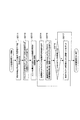
図20は、上記の磁気記録再生方式を採用した記録装置500の構成を示す図である。 FIG. 20 is a diagram showing the configuration of a recording apparatus 500 that employs the magnetic recording / reproducing method described above.
同図に示すように、この記録装置500は、マルチトラック化部110、マルチトラック記録符号化部120、マルチトラックプリアンブル付加部130、マルチトラック記録部140、記録ヘッドアレイ150で構成される。
As shown in the figure, the recording apparatus 500 includes a
マルチトラック化部110は、マルチトラック化のために記録データ1を記録ヘッドアレイ150に設けられた記録ヘッドW−1,W−2,W−3の数(M=3)分のデータに振り分けるデータ分配器111で構成される。
The
マルチトラック記録符号化部120は、データ分配器111にてM個に振り分けられた記録データを符号化するM個の記録符号化部121−1,121−2,121−3で構成される。
The multitrack
マルチトラックプリアンブル付加部130は、マルチトラック記録符号化部120によって符号化された各記録データに、トラックごとに特定のプリアンブルを付加するM個のプリアンブル付加部131−1,131−2,131−3で構成される。
The multitrack
マルチトラック記録部140は、プリアンブルが付加された各トラックの記録符号列を記録媒体に記録する手段であり、より詳細には、プリアンブルが付加された記録符号列に所望のタイミングを与えるM個の出力タイミング設定部141−1,141−2,141−3と、記録補償処理を行うM個の記録補償部144−1,144−2,144−3と、記録補償処理後の記録符号列をもとに個々の記録ヘッドW−1,W−2,W−3を駆動するM個の記録アンプ147−1,147−2,147−3とで構成される。
The
図21は、この記録装置500によるユニット記録の動作を示すフローチャートである。この記録装置100では、まず、入力された記録データ1がマルチトラック化部110にて、記録ヘッドW−1,W−2,W−3の数(M=3)のデータ、すなわちユニットを構成するトラック数分のデータに分配される(ステップS501)。
FIG. 21 is a flowchart showing the unit recording operation by the recording apparatus 500. In this recording apparatus 100, first, the
分配された各データは、それぞれマルチトラック記録符号化部120の記録符号化部121−1,121−2,121−3にて、磁気記録メディア2の記録再生特性を考慮した符号列に符号化される。このときデータの符号列に、復調用同期パターンなどの、データ復調時に必要な情報も付加される(ステップS502)。
Each distributed data is encoded into a code string in consideration of recording / reproducing characteristics of the
次に、符号化されたそれぞれの記録データの所定の位置に、マルチトラックプリアンブル付加部130のプリアンブル付加部131−1,131−2,131−3にて、ユニット単位のデータを再生する制御のために必要なパターンがプリアンブルとして付加され、記録符号列が得られる(ステップS503)。
Next, control of reproducing unit-unit data by the preamble adding units 131-1, 131-2, and 131-3 of the multi-track
ここで、符号化されたそれぞれの記録データの所定の位置とは、連続して記録符号列が記録再生されることを考慮して決められた位置である。また、プリアンブルとしては、例えば、再生信号に対するゲイン制御のための学習に用いられるゲイン制御パターン、ビット同期処理などに用いられる同期パターン、及び、複数の再生ヘッドと1ユニット分の複数のトラックとのトラック幅方向の位置関係に相当するチャネル行列を演算するために必要な分離パターンなどがある。ここで、1ユニット分の複数のトラックとは、データを再生するための信号処理の一単位を構成する複数のトラックである。同期パターンはトラックごとの分離パターンやデータの開始位置を特定するための情報としても用いられる。これらのパターンは、マルチトラック記録符号化部120の記録符号化部121−1,121−2,121−3で生成される符号列の規則を考慮して作成されたものである。
Here, the predetermined position of each encoded recording data is a position determined in consideration that recording code strings are continuously recorded and reproduced. The preamble includes, for example, a gain control pattern used for learning for gain control with respect to a reproduction signal, a synchronization pattern used for bit synchronization processing, and a plurality of reproduction heads and a plurality of tracks for one unit. There are separation patterns necessary to calculate a channel matrix corresponding to the positional relationship in the track width direction. Here, the plurality of tracks for one unit are a plurality of tracks constituting one unit of signal processing for reproducing data. The synchronization pattern is also used as information for specifying the separation pattern for each track and the start position of data. These patterns are created in consideration of the rules of the code strings generated by the recording encoding units 121-1, 121-2, and 121-3 of the multitrack
それぞれのトラックごとの記録符号列は、マルチトラック記録部140の出力タイミング設定部141−1,141−2,141−3にて所望のタイミングが与えられた後、記録補償部144−1,144−2,144−3にて、磁気記録メディア2への記録に最適化するための記録補償処理が施される。
The recording code string for each track is given a desired timing by the output timing setting units 141-1, 141-2, and 141-3 of the
この後、トラックごとの記録符号列は、記録アンプ147−1,147−2,147−3において電圧から電流に変換されて記録ヘッドW−1,W−2,W−3に送られ、記録ヘッドW−1,W−2,W−3によって磁気記録メディア2に記録される(ステップS504)。
Thereafter, the recording code string for each track is converted from a voltage to a current by the recording amplifiers 147-1, 147-2, and 147-3 and sent to the recording heads W-1, W-2, and W-3 for recording. Recording is performed on the
そして、以上の磁気記録メディア2へのユニット単位の記録動作は、トラック方向に複数のユニットが連続して配置されるように繰り返される。
The above unit-unit recording operation on the
次に、上記の磁気記録再生方式を採用した再生装置について説明する。 Next, a reproducing apparatus employing the above magnetic recording / reproducing system will be described.
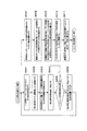
図22は上記の磁気記録再生方式を採用した再生装置600の構成を示す図である。 FIG. 22 is a diagram showing a configuration of a reproducing apparatus 600 that employs the above-described magnetic recording / reproducing method.
同図に示すように、この再生装置600は、再生ヘッドアレイ210、チャネル再生部220、信号分離部230、マルチトラック復調部240、及び復元部260を備える。
As shown in the figure, the reproducing apparatus 600 includes a reproducing
再生ヘッドアレイ210は、磁気記録メディア2に記録された各トラックから信号を読み出すN(N=3)個の再生ヘッドR−1,R−2,R−3を有する。それぞれの再生ヘッドR−1,R−2,R−3は、磁気記録メディア2上で隣接する1以上のトラックから信号を再生することが可能なように、そのヘッド幅及び配置が決められている。
The reproducing
チャネル再生部220は、再生ヘッドアレイ210に搭載されたN個の再生ヘッドR−1,R−2,R−3によって再生された信号を増幅するN個の再生アンプ221−1,221−2,221−3と、N個の再生アンプ221−1,221−2,221−3の出力の振幅レベルが所定の値になるようにゲインを制御するゲイン調整部224−1,224−2,224−3と、ゲイン調整部224−1,224−2,224−3の出力を所定のビット幅のディジタル値に量子化するA/Dコンバータ225−1,225−2,225−3とを備える。
The
なお、A/Dコンバータ225−1,225−2,225−3の直前には必要に応じて不要な高域成分を除去するローパス・フィルタが備えられていてもよい。 Note that a low-pass filter that removes unnecessary high-frequency components may be provided immediately before the A / D converters 225-1, 225-2, and 225-3 as necessary.
また、ゲイン調整部224−1,224−2,224−3は、A/Dコンバータ225−1,225−2,225−3の前段ではなく後段に配置されてもよい。これは、A/Dコンバータ225−1,225−2,225−3のビット幅をより有効に用いたり、ゲイン調整部224−1,224−2,224−3の構成を、プリアンプルに含まれる各パターンの検出を考慮した簡単なものとしたい場合に有効である。 Further, the gain adjusting units 224-1, 224-2, and 224-3 may be arranged not in the preceding stage of the A / D converters 225-1, 225-2, and 225-3 but in the subsequent stage. This is because the bit widths of the A / D converters 225-1, 225-2, and 225-3 are used more effectively, and the configurations of the gain adjusting units 224-1, 244-2, and 224-3 are included in the preample. This is effective when it is desired to make it simple considering the detection of each pattern.
信号分離部230は、A/Dコンバータ225−1,225−2,225−3の出力から同期パターンの検出を行う同期信号検出器231と、同期信号検出器231によって検出された同期信号をもとに分離パターンの開始位置を特定して、その分離パターンを用いてチャネル推定演算および信号分離演算を行うことによって、複数の再生ヘッドR−1,R−2,R−3によってそれぞれ再生された1ユニット分の再生信号からトラックごとの再生信号を分離する信号分離処理部236とを備える。
The
マルチトラック復調部240は、信号分離処理部236にて分離されたトラックごとの再生信号に対して等化処理を行うM個の等化器241−1,241−2,241−3と、等化器241−1,241−2,241−3の出力からビット同期を行うM個のPLL242−1,242−2,242−3と、PLL242−1,242−2,242−3で生成されたビット同期信号を用いて各トラックごとの再生信号を二値化して符号列を生成する、たとえばビタビ検出器などM個の検出器243−1,243−2,243−3と、検出器243−1,243−2,243−3の出力である2値化された再生信号から符号列上の同期パターンを検出するM個の同期信号検出器244−1,244−2,244−3と、同期信号検出器244−1,244−2,244−3により検出された同期パターンをもとにデータの開始位置を特定して符号列からデータ列を復号するM個の復号器245−1,245−2,245−3とを備える。
The
復元部260は、マルチトラック復調部240内のM個の復号器245−1,245−2,245−3より出力された各トラックのデータを、記録時と逆の動作により連結して再生データ3を復元するデータ結合器261を備える。
The
図23は、この再生装置600のユニット再生の動作の流れを示すフローチャートである。この再生装置600では、まず、それぞれ隣接する1以上のトラックから信号を再生することが可能なN個の再生ヘッドR−1,R−2,R−3によって、磁気記録メディア2の1ユニット分の複数のトラックから信号が再生される(ステップS601)。
FIG. 23 is a flowchart showing a unit reproduction operation flow of the reproduction apparatus 600. In this reproducing apparatus 600, first, one unit of the
次に、ゲイン調整部224−1,224−2,224−3にて、各再生アンプ221−1,221−2,221−3の出力の振幅レベルが調整された後、ゲイン調整部224−1,224−2,224−3の出力はA/Dコンバータ225−1,225−2,225−3にてディジタル値に変換されて同期信号検出器231に出力される(ステップS602)。 Next, after the gain adjustment units 224-1, 224-2, and 224-3 adjust the amplitude levels of the outputs of the reproduction amplifiers 221-1, 221-2, and 221-3, the gain adjustment unit 224- The outputs of 1, 244-2 and 224-3 are converted into digital values by the A / D converters 225-1, 225-2, and 225-3 and output to the synchronization signal detector 231 (step S602).
同期信号検出器231は、A/Dコンバータ225−1,225−2,225−3の出力ごとに、プリアンブル内の分離パターンの開始位置などを知るための同期パターンの検出を行う(ステップS603)。
The
次に、信号分離処理部236は、同期信号検出器231によって検出された同期信号をもとに分離パターンの開始位置を特定して、その分離パターンを用いてチャネル推定演算によって各再生ヘッドR−1,R−2,R−3と1ユニット分の複数のトラックとのトラック幅方向の位置関係に相当するチャネル行列を求めた後(ステップS604)、このチャネル行列をもとに、各再生ヘッドR−1,R−2,R−3によって再生された1ユニット分の再生信号から、トラックR−1,R−2,R−3ごとの再生信号を分離する(ステップS605)。
Next, the signal
この後は、トラックごとの再生信号からマルチトラック復調部240にてデータ列の復号が行われ(ステップS606)、復元部260にて各トラックごとのデータが連結されて再生データ3が得られる(ステップS607)。
After this, the
ところで上記の磁気記録再生方式を採用する場合における、より安定した再生信号を得るための技術的課題の一つとしては、例えば、トラックずれに対する追随性の向上がある。 By the way, as one of the technical problems for obtaining a more stable reproduction signal in the case of employing the above magnetic recording / reproducing method, there is, for example, an improvement in followability with respect to a track shift.
すなわち、上記の磁気記録再生方式では、再生中に外乱等によりトラッキングが不安定となった場合、個々の再生ヘッドの各トラックに対するトラック幅方向での位置関係が変動し、これによって良好なチャネル推定情報が得られなくなることで、再生が不安定になるおそれがある。 In other words, in the above magnetic recording / reproducing system, when tracking becomes unstable due to disturbance or the like during reproduction, the positional relationship in the track width direction with respect to each track of each reproducing head fluctuates. If information cannot be obtained, reproduction may become unstable.
本発明は、かかる事情を鑑み、トラックずれに対するデータ再生の安定化を図ることのできる再生装置、再生方法、記録装置、記録方法、記録再生装置、データフォーマット、及び記録媒体を提供しようとするものである。 In view of such circumstances, the present invention intends to provide a reproducing apparatus, a reproducing method, a recording apparatus, a recording method, a recording / reproducing apparatus, a data format, and a recording medium capable of stabilizing data reproduction against a track shift. It is.
上記の課題を解決するために、本発明の再生装置は、複数のトラックを有し、前記トラックごとに、データと、1以上の前記トラックに跨って信号を再生することが可能な再生ヘッドと前記複数のトラックとの再生時のトラック幅方向の位置関係を検出するために必要なパターンを含むプリアンブルとが記録され、前記複数のトラックの前記データ及び前記プリアンブルを前記データを再生するための信号処理の一単位であるユニットとして、複数の前記ユニットがトラック方向に連続して記録された記録媒体から前記データを再生する装置であって、前記ユニットごとの前記パターンの再生信号をもとに、前記再生ヘッドと前記複数のトラックとの再生時のトラック幅方向の位置関係に相当するチャネル行列を演算するチャネル推定演算部と、前記ユニット内の前記パターンの再生信号をもとに前記チャネル推定演算部にて求められたチャネル行列から、前記データの区間内で可変のチャネル行列を推定するチャネル行列推定部と、前記チャネル行列推定部により推定された可変のチャネル行列を用いて、前記再生ヘッドによって再生された前記1ユニット分の前記データの再生信号から、前記トラックごとの前記データの再生信号を分離する信号分離演算部とを具備する。 In order to solve the above-described problem, a reproducing apparatus according to the present invention includes a plurality of tracks, and a reproducing head capable of reproducing data for each track and a signal across one or more of the tracks. A preamble including a pattern necessary for detecting a positional relationship in the track width direction during reproduction with the plurality of tracks, and a signal for reproducing the data of the plurality of tracks and the preamble As a unit that is a unit of processing, a device that reproduces the data from a recording medium in which a plurality of units are continuously recorded in the track direction, based on the reproduction signal of the pattern for each unit, A channel estimation calculation unit for calculating a channel matrix corresponding to the positional relationship in the track width direction during reproduction between the reproduction head and the plurality of tracks A channel matrix estimator that estimates a variable channel matrix within the data interval from the channel matrix obtained by the channel estimation calculator based on the reproduction signal of the pattern in the unit; and the channel matrix A signal separation calculation unit that separates the reproduction signal of the data for each track from the reproduction signal of the data for one unit reproduced by the reproduction head using the variable channel matrix estimated by the estimation unit; It comprises.
この発明によれば、データの区間内で、再生ヘッドと複数のトラックとのトラック幅方向の位置関係に相当するチャネル行列をトラックずれの状況に応じて可変にすることによって、トラックずれに対するデータ再生の安定化を図ることができる。 According to the present invention, data reproduction with respect to track deviation is made possible by making the channel matrix corresponding to the positional relationship between the reproduction head and the plurality of tracks in the track width direction variable in accordance with the track deviation situation within the data section. Can be stabilized.
本発明の再生装置において、前記チャネル行列推定部は、連続する複数の前記ユニット内の前記パターンの再生信号をもとに前記チャネル推定演算部にて求められた複数のチャネル行列を用いて、前記データの区間内で可変のチャネル行列を推定することとしてよい。これにより、トラックずれの状況をより正確に検出することができ、トラックずれに対するデータ再生の安定化を図ることができる。 In the reproduction apparatus of the present invention, the channel matrix estimation unit uses the plurality of channel matrices obtained by the channel estimation calculation unit based on the reproduction signals of the pattern in the plurality of consecutive units. A variable channel matrix may be estimated within the data interval. As a result, the track shift state can be detected more accurately, and the data reproduction against the track shift can be stabilized.
本発明の再生装置において、前記チャネル行列推定部は、連続する複数の前記ユニット内の前記パターンの再生信号をもとに前記チャネル推定演算部によってそれぞれ求められた複数のチャネル行列から、前記データの区間を分割した個々の区間にそれぞれ対応する複数のチャネル行列を推定し、前記信号分離演算部は、前記チャネル行列推定部によって得られた前記複数のチャネル行列を用いて、前記個々の区間ごとに、前記再生ヘッドによって再生された前記1ユニット分の前記データの再生信号から、前記トラックごとの前記データの再生信号を分離することとしてもよい。これにより、データの区間を分割した個々の区間ごとに、トラックずれの状況に応じた適切なチャネル行列を得ることができ、トラックずれに対するデータ再生の安定化を図ることができる。 In the reproduction apparatus of the present invention, the channel matrix estimation unit may calculate the data from a plurality of channel matrices respectively obtained by the channel estimation calculation unit based on reproduction signals of the pattern in a plurality of consecutive units. A plurality of channel matrices corresponding to each of the sections obtained by dividing the section are estimated, and the signal separation calculation unit uses the plurality of channel matrices obtained by the channel matrix estimation unit for each individual section. The reproduction signal of the data for each track may be separated from the reproduction signal of the data for one unit reproduced by the reproduction head. As a result, an appropriate channel matrix corresponding to the track shift state can be obtained for each section obtained by dividing the data section, and the data reproduction against the track shift can be stabilized.
本発明の再生装置において、前記チャネル行列推定部は、連続する複数の前記ユニット内の前記パターンの再生信号をもとに前記チャネル推定演算部によって求められた複数のチャネル行列から、直線補間によって、前記データの個々の区間にそれぞれ対応する複数のチャネル行列を推定することとしてもよい。このようにして直線補間を用いることで、データの区間を分割した個々の区間ごとに、トラックずれの状況に応じた適切なチャネル行列を得ることができ、トラックずれに対するデータ再生の安定化を図ることができる。 In the reproduction apparatus of the present invention, the channel matrix estimation unit is configured by linear interpolation from a plurality of channel matrices obtained by the channel estimation calculation unit based on the reproduction signals of the patterns in the plurality of consecutive units. A plurality of channel matrices respectively corresponding to the individual sections of the data may be estimated. By using linear interpolation in this way, it is possible to obtain an appropriate channel matrix corresponding to the track shift situation for each section obtained by dividing the data section, and to stabilize the data reproduction against the track shift. be able to.
本発明の再生装置において、前記チャネル行列推定部は、連続する2つの前記ユニット内の前記パターンの再生信号をもとに前記チャネル推定演算部によって求められた2つのチャネル行列から、前記2つのユニット内の前記プリアンブルに挟まれたデータの区間内で可変のチャネル行列を推定することとしてもよい。また、前記チャネル行列推定部は、連続する複数の前記ユニット内の前記パターンの再生信号をもとに前記チャネル推定演算部によって求められた複数のチャネル行列から、前記複数のパターンの両方よりも後方に位置するデータの区間内で可変のチャネル行列を推定することとしてもよい。 In the reproduction apparatus of the present invention, the channel matrix estimation unit includes the two units from two channel matrices obtained by the channel estimation calculation unit based on the reproduction signals of the pattern in the two consecutive units. A variable channel matrix may be estimated within a section of data sandwiched between the preambles. In addition, the channel matrix estimation unit is behind the both of the plurality of patterns from the plurality of channel matrices obtained by the channel estimation calculation unit based on the reproduction signals of the patterns in the plurality of consecutive units. It is also possible to estimate a variable channel matrix within the data section located at.
前記パターンとしては、前記トラックごとにユニークな位置に配置された、最小記録波長と同等あるいはそれ以上の記録波長の信号からなる分離パターンを用いることができる。また、トラッキングサーボ情報を用いてもよい。 As the pattern, a separation pattern composed of a signal having a recording wavelength equal to or greater than the minimum recording wavelength and disposed at a unique position for each track can be used. Also, tracking servo information may be used.
本発明の再生装置において、前記信号分離演算部は、前記チャネル行列推定部により推定された前記可変のチャネル行列の一般化逆行列を求め、この一般化逆行列と、前記再生ヘッドによって再生された前記1ユニット分の前記データの再生信号とから、前記トラックごとの前記データの再生信号を分離することとしてもよい。また、前記信号分離演算部は、前記チャネル行列推定部により推定された可変のチャネル行列に対して、MMSE(Minimum Mean Squared Error)法により、前記トラックごとの前記データの再生信号を分離することとしてもよい。 In the reproducing apparatus of the present invention, the signal separation calculation unit obtains a generalized inverse matrix of the variable channel matrix estimated by the channel matrix estimation unit, and the generalized inverse matrix and the reproduction head reproduce The data reproduction signal for each track may be separated from the data reproduction signal for one unit. Further, the signal separation calculation unit separates the reproduction signal of the data for each track by a MMSE (Minimum Mean Squared Error) method from the variable channel matrix estimated by the channel matrix estimation unit. Also good.
本発明の再生装置は、前記1ユニット分の複数のトラックに対してそれぞれ異なる位置関係で信号を再生可能なように、前記再生ヘッドを複数備えたものであってもよい。 The reproducing apparatus of the present invention may include a plurality of reproducing heads so that signals can be reproduced with different positional relationships with respect to the plurality of tracks of one unit.
本発明の別の観点に基づく再生方法は、複数のトラックを有し、前記トラックごとに、データと、1以上の前記トラックに跨って信号を再生することが可能な再生ヘッドと前記複数のトラックとの再生時のトラック幅方向の位置関係を検出するために必要なパターンを含むプリアンブルとが記録され、前記複数のトラックの前記データ及び前記プリアンブルを前記データを再生するための信号処理の一単位であるユニットとして、複数のユニットがトラック方向に連続して記録された記録媒体から前記データを再生する方法であって、前記ユニットごとの前記パターンの再生信号をもとに、前記再生ヘッドと前記複数のトラックとの再生時のトラック幅方向の位置関係に相当するチャネル行列を演算するステップと、連続する複数の前記ユニット内の前記パターンの再生信号をもとに前記チャネル行列演算ステップにてそれぞれ求められた複数のチャネル行列を用いて、前記データの区間内で可変のチャネル行列を推定するステップと、前記推定された可変のチャネル行列を用いて、前記再生ヘッドによって再生された前記1ユニット分の前記データの再生信号から、前記トラックごとの前記データの再生信号を分離するステップとを具備する。 A playback method according to another aspect of the present invention includes a plurality of tracks, a playback head capable of playing back data over each of the tracks, and the plurality of tracks. And a preamble including a pattern necessary for detecting the positional relationship in the track width direction during reproduction, and a unit of signal processing for reproducing the data of the plurality of tracks and the preamble The unit is a method for reproducing the data from a recording medium in which a plurality of units are continuously recorded in the track direction, and based on the reproduction signal of the pattern for each unit, the reproduction head and the unit Calculating a channel matrix corresponding to the positional relationship in the track width direction during reproduction with a plurality of tracks, and a plurality of consecutive units. Estimating a variable channel matrix within a section of the data using a plurality of channel matrices respectively obtained in the channel matrix calculation step based on the reproduction signal of the pattern in the network; and Separating the data reproduction signal for each track from the data reproduction signal for the unit reproduced by the reproduction head using the variable channel matrix.
この発明によれば、データの区間内で、再生ヘッドと複数のトラックとのトラック幅方向の位置関係に相当するチャネル行列をトラックずれの状況に応じて可変することによって、トラックずれに対するデータ再生の安定化を図ることができる。 According to the present invention, by changing the channel matrix corresponding to the positional relationship in the track width direction between the reproducing head and the plurality of tracks in the data section, the data reproduction for the track deviation can be performed. Stabilization can be achieved.
本発明の別の観点に基づく記録装置は、記録媒体に複数のトラックを記録する装置であって、前記トラックごとに記録すべきデータを符号化するマルチトラック記録符号化部と、前記マルチトラック記録符号化部により符号化された前記トラックごとの前記データの符号列にそれぞれ、1以上の前記トラックに跨って信号を再生することが可能な再生ヘッドと前記複数のトラックとの再生時のトラック幅方向の位置関係を検出するために必要なパターンを含むプリアンブルを付加するマルチトラックプリアンブル付加部と、前記複数のトラックの前記プリアンブル及び前記データを、前記データを再生するための信号処理の一単位であるユニットとして、このユニットが前記トラック方向に複数配置されるように、前記マルチトラックプリアンブル付加部によって前記プリアンブルが付加された前記トラックごとのデータを前記記録ヘッドにより前記記録媒体に記録するマルチトラック記録部とを具備する。 A recording apparatus according to another aspect of the present invention is an apparatus for recording a plurality of tracks on a recording medium, the multitrack recording encoding unit encoding data to be recorded for each track, and the multitrack recording Track width at the time of reproduction of the reproduction head and the plurality of tracks each capable of reproducing a signal across one or more of the tracks in the code string of the data for each track encoded by the encoding unit A multi-track preamble adding unit for adding a preamble including a pattern necessary for detecting the positional relationship of directions, and the preamble and the data of the plurality of tracks as a unit of signal processing for reproducing the data. As a unit, the multi-track preamplifier is arranged so that a plurality of units are arranged in the track direction. Comprising a multi-track recording section for recording on the recording medium by the recording head of data of each of the tracks the preamble has been added by the bull adding unit.
この発明によれば、複数のトラックのプリアンブル及びデータを、データを再生するための信号処理の一単位であるユニットとして、このユニットをトラック方向に複数配置して記録媒体に記録することができるので、本発明の再生装置において、連続する複数のユニット内のパターンの再生信号からチャネル推定演算によってそれぞれのチャネル行列を求め、これら複数のチャネル行列を用いて、データの区間内で可変のチャネル行列を推定して、推定された可変のチャネル行列を用いて、前記再生ヘッドによって再生された前記1ユニット分の前記データの再生信号から、前記トラックごとの前記データの再生信号を分離することが可能になる。 According to the present invention, the preamble and data of a plurality of tracks can be recorded on a recording medium by arranging a plurality of units in the track direction as a unit that is a unit of signal processing for reproducing data. In the playback apparatus of the present invention, each channel matrix is obtained by channel estimation calculation from the playback signals of patterns in a plurality of consecutive units, and a variable channel matrix is obtained within the data interval using these channel matrices. By estimating and using the estimated variable channel matrix, it is possible to separate the data reproduction signal for each track from the data reproduction signal for the unit reproduced by the reproduction head. Become.
本発明の記録装置において、前記マルチトラックプリアンブル付加部は、前記トラックの最後に記録される前記データ以外のデータに対してはこのデータの前に前記プリアンブルを付加し、前記トラックの最後に記録される前記データに対してはこのデータの前後に前記プリアンブルを付加することとしてもよい。これにより、本発明の再生装置にて、データの前後に配置された2つのプリアンブル内のパターンの再生信号からそれぞれチャネル推定演算によって複数のチャネル行列を演算して、これら複数のチャネル行列を用いて、データの区間内で可変のチャネル行列を推定することが可能になる。 In the recording apparatus of the present invention, the multi-track preamble adding unit adds the preamble to the data other than the data recorded at the end of the track and records the data at the end of the track. The preamble may be added to the data before and after the data. Thus, in the playback device of the present invention, a plurality of channel matrices are calculated by channel estimation calculation from the playback signals of the patterns in the two preambles arranged before and after the data, and the plurality of channel matrices are used. This makes it possible to estimate a variable channel matrix within a data interval.
本発明の別の観点に基づく記録方法は、記録媒体に複数のトラックを記録する方法であって、前記トラックごとに記録すべきデータを符号化するステップと、前記符号化された前記トラックごとの前記データの符号列にそれぞれ、1以上の前記トラックに跨って信号を再生することが可能な再生ヘッドと前記複数のトラックとの再生時のトラック幅方向の位置関係を検出するために必要なパターンを含むプリアンブルを付加するステップと、前記複数のトラックの前記プリアンブル及び前記データを、前記データを再生するための信号処理の一単位であるユニットとして、このユニットが前記トラック方向に複数配置されるように、前記プリアンブルが付加された前記トラックごとのデータを前記記録ヘッドにより前記記録媒体に記録するステップとを具備する。 According to another aspect of the present invention, there is provided a recording method for recording a plurality of tracks on a recording medium, the step of encoding data to be recorded for each track, and for each of the encoded tracks. A pattern necessary for detecting the positional relationship in the track width direction during reproduction between the reproduction head capable of reproducing a signal over one or more of the tracks and the plurality of tracks in the data code string And adding a plurality of units in the track direction as a unit that is a unit of signal processing for reproducing the data, the preamble and the data of the plurality of tracks. In addition, the data for each track to which the preamble is added is recorded on the recording medium by the recording head. Tsu; and a flop.
この発明によれば、複数のトラックのプリアンブル及びデータを、データを再生するための信号処理の一単位であるユニットとして、このユニットをトラック方向に複数配置して記録媒体に記録することができるので、本発明の再生装置において、連続する複数のユニット内のパターンの再生信号からチャネル推定演算によってそれぞれのチャネル行列を求め、これら複数のチャネル行列を用いて、データの区間内で可変のチャネル行列を推定して、推定された可変のチャネル行列を用いて、前記再生ヘッドによって再生された前記1ユニット分の前記データの再生信号から、前記トラックごとの前記データの再生信号を分離することが可能になる。 According to the present invention, the preamble and data of a plurality of tracks can be recorded on a recording medium by arranging a plurality of units in the track direction as a unit that is a unit of signal processing for reproducing data. In the playback apparatus of the present invention, each channel matrix is obtained by channel estimation calculation from the playback signals of patterns in a plurality of consecutive units, and a variable channel matrix is obtained within the data interval using these channel matrices. By estimating and using the estimated variable channel matrix, it is possible to separate the data reproduction signal for each track from the data reproduction signal for the unit reproduced by the reproduction head. Become.
本発明の別の観点に基づくデータフォーマットは、複数のトラックを有し、前記トラックごとに、データと、1以上の前記トラックに跨って信号を再生することが可能な再生ヘッドと前記複数のトラックとの再生時のトラック幅方向の位置関係を検出するために必要なパターンを含むプリアンブルとが配置され、前記複数のトラックの前記データ及び前記プリアンブルが、前記データを再生するための信号処理の一単位として、前記複数のトラックにそれぞれ連続して配置されたものである。 A data format according to another aspect of the present invention includes a plurality of tracks, and each track has data, a reproducing head capable of reproducing a signal across the one or more tracks, and the plurality of tracks. And a preamble including a pattern necessary for detecting a positional relationship in the track width direction during reproduction, and the data of the plurality of tracks and the preamble are used for signal processing for reproducing the data. As a unit, each unit is continuously arranged on the plurality of tracks.
このデータフォーマットによれば、本発明の再生装置において、連続する複数のユニット内のパターンの再生信号からチャネル推定演算によってそれぞれのチャネル行列を求め、これら複数のチャネル行列を用いて、データの区間内で可変のチャネル行列を推定して、推定された可変のチャネル行列を用いて、前記再生ヘッドによって再生された前記1ユニット分の前記データの再生信号から、前記トラックごとの前記データの再生信号を分離することが可能になる。 According to this data format, in the playback apparatus of the present invention, each channel matrix is obtained by channel estimation calculation from a playback signal of a pattern in a plurality of consecutive units, and the data within a data section is obtained using these plurality of channel matrices. The variable channel matrix is estimated by using the estimated variable channel matrix, and the reproduction signal of the data for each track is obtained from the reproduction signal of the data for one unit reproduced by the reproduction head. It becomes possible to separate.
本発明のデータフォーマットは、前記データの前後に前記プリアンブルが配置されたものであってもよい。これにより、これにより、本発明の再生装置にて、データの前後に配置された2つのプリアンブル内のパターンの再生信号からそれぞれチャネル推定演算によって複数のチャネル行列を演算して、これら複数のチャネル行列を用いて、データの区間内で可変のチャネル行列を推定することが可能になる。 The data format of the present invention may be one in which the preamble is arranged before and after the data. Thereby, in the playback device of the present invention, a plurality of channel matrices are calculated by channel estimation calculation from the playback signals of the patterns in the two preambles arranged before and after the data, and the plurality of channel matrices are obtained. Can be used to estimate a variable channel matrix within a data interval.
本発明の別の観点に基づく記録媒体は、複数のトラックを有し、前記トラックごとに、データと、1以上の前記トラックに跨って信号を再生することが可能な再生ヘッドと前記複数のトラックとの再生時のトラック幅方向の位置関係を検出するために必要なパターンを含むプリアンブルとが記録され、前記複数のトラックの前記データ及び前記プリアンブルが、前記データを再生するための信号処理の一単位としてトラック方向に連続して記録されたものである。 A recording medium according to another aspect of the present invention has a plurality of tracks, and for each track, data, a reproducing head capable of reproducing a signal across one or more of the tracks, and the plurality of tracks And a preamble including a pattern necessary for detecting the positional relationship in the track width direction at the time of reproduction, and the data of the plurality of tracks and the preamble are used for signal processing for reproducing the data. It is recorded continuously in the track direction as a unit.
本発明の再生装置、再生方法、記録装置、記録方法、記録再生装置、データフォーマット、及び記録媒体によれば、トラックずれに対するデータ再生の安定化を図ることができる。 According to the reproducing apparatus, reproducing method, recording apparatus, recording method, recording / reproducing apparatus, data format, and recording medium of the present invention, it is possible to stabilize data reproduction against track deviation.
以下、本発明の実施形態を図面に基づき詳細に説明する。 Hereinafter, embodiments of the present invention will be described in detail with reference to the drawings.
(第1の実施形態) (First embodiment)
本発明の第1の実施形態として、マルチヘッドを用いた磁気記録再生方式について説明する。ここで記録ヘッドの数をM、再生ヘッドの数をNとし、この実施形態では、M=3、N=3とする。 As a first embodiment of the present invention, a magnetic recording / reproducing system using a multi-head will be described. Here, the number of recording heads is M, the number of reproducing heads is N, and in this embodiment, M = 3 and N = 3.
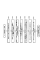
図1は、本発明の第1の実施形態の磁気記録再生方式における記録装置100の構成を示す図である。 FIG. 1 is a diagram showing a configuration of a recording apparatus 100 in the magnetic recording / reproducing system according to the first embodiment of the present invention.
同図に示すように、この記録装置100は、マルチトラック化部110、マルチトラック記録符号化部120、マルチトラックプリアンブル付加部130、マルチトラック記録部140、記録ヘッドアレイ150で構成される。
As shown in the figure, the recording apparatus 100 includes a
マルチトラック化部110は、マルチトラック化のために記録データ1を記録ヘッドアレイ150に設けられた記録ヘッドW−1,W−2,W−3の数(M=3)分のデータに振り分けるデータ分配器111で構成される。
The
マルチトラック記録符号化部120は、データ分配器111にてM個に振り分けられた記録データを符号化するM個の記録符号化部121−1,121−2,121−3で構成される。
The multitrack
マルチトラックプリアンブル付加部130は、マルチトラック記録符号化部120によって符号化された各記録データに、トラックごとに特定のプリアンブルを付加するM個のプリアンブル付加部131−1,131−2,131−3で構成される。
The multitrack
マルチトラック記録部140は、プリアンブルが付加された各トラックの記録符号列を記録媒体に記録する手段であり、より詳細には、プリアンブルが付加された記録符号列に所望のタイミングを与えるM個の出力タイミング設定部141−1,141−2,141−3と、記録補償処理を行うM個の記録補償部144−1,144−2,144−3と、記録補償処理後の記録符号列をもとに個々の記録ヘッドW−1,W−2,W−3を駆動するM個の記録アンプ147−1,147−2,147−3とで構成される。
The
図2は、この記録装置100によるユニット記録の動作を示すフローチャートである。この記録装置100では、まず、入力された記録データ1がマルチトラック化部110にて、記録ヘッドW−1,W−2,W−3の数(M=3)のデータ、すなわちユニットを構成するトラック数分のデータに分配される(ステップS101)。
FIG. 2 is a flowchart showing the unit recording operation by the recording apparatus 100. In this recording apparatus 100, first, the
分配された各データは、それぞれマルチトラック記録符号化部120の記録符号化部121−1,121−2,121−3にて、磁気記録メディア2の記録再生特性を考慮した符号列に符号化される。このときデータの符号列に、復調用同期パターンなどの、データ復調時に必要な情報も付加される(ステップS102)。
Each distributed data is encoded into a code string in consideration of recording / reproducing characteristics of the
次に、符号化されたそれぞれの記録データの所定の位置に、マルチトラックプリアンブル付加部130のプリアンブル付加部131−1,131−2,131−3にて、ユニット単位のデータを再生する制御のために必要なパターンがプリアンブルとして付加され、記録符号列が得られる(ステップS103)。
Next, control of reproducing unit-unit data by the preamble adding units 131-1, 131-2, and 131-3 of the multi-track
ここで、符号化されたそれぞれの記録データの所定の位置とは、連続して記録符号列が記録再生されることを考慮して決められた位置である。また、プリアンブルとしては、例えば、再生信号に対するゲイン制御のための学習に用いられるゲイン制御パターン、ビット同期処理などに用いられる同期パターン、及び、複数の再生ヘッドと1ユニット分の複数のトラックとのトラック幅方向の位置関係に相当するチャネル行列を演算するために必要な分離パターンなどがある。ここで、1ユニット分の複数のトラックとは、データを再生するための信号処理の一単位を構成する複数のトラックである。同期パターンはトラックごとの分離パターンやデータの開始位置を特定するための情報としても用いられる。これらのパターンは、マルチトラック記録符号化部120の記録符号化部121−1,121−2,121−3で生成される符号列の規則を考慮して作成されたものである。
Here, the predetermined position of each encoded recording data is a position determined in consideration that recording code strings are continuously recorded and reproduced. The preamble includes, for example, a gain control pattern used for learning for gain control with respect to a reproduction signal, a synchronization pattern used for bit synchronization processing, and a plurality of reproduction heads and a plurality of tracks for one unit. There are separation patterns necessary to calculate a channel matrix corresponding to the positional relationship in the track width direction. Here, the plurality of tracks for one unit are a plurality of tracks constituting one unit of signal processing for reproducing data. The synchronization pattern is also used as information for specifying the separation pattern for each track and the start position of data. These patterns are created in consideration of the rules of the code strings generated by the recording encoding units 121-1, 121-2, and 121-3 of the multitrack
それぞれのトラックごとの記録符号列は、マルチトラック記録部140の出力タイミング設定部141−1,141−2,141−3にて所望のタイミングが与えられた後、記録補償部144−1,144−2,144−3にて、磁気記録メディア2への記録に最適化するための記録補償処理が施される。
The recording code string for each track is given a desired timing by the output timing setting units 141-1, 141-2, and 141-3 of the
この後、トラックごとの記録符号列は、記録アンプ147−1,147−2,147−3において電圧から電流に変換されて記録ヘッドW−1,W−2,W−3に送られ、記録ヘッドW−1,W−2,W−3によって磁気記録メディア2に記録される(ステップS104)。
Thereafter, the recording code string for each track is converted from a voltage to a current by the recording amplifiers 147-1, 147-2, and 147-3 and sent to the recording heads W-1, W-2, and W-3 for recording. Recording is performed on the
そして、以上の磁気記録メディア2へのユニット単位の記録動作は、トラック方向に複数のユニットが連続して配置されるように繰り返される。
The above unit-unit recording operation on the
次に、本発明の第1の実施形態の磁気記録再生方式における再生装置について説明する。 Next, a reproducing apparatus in the magnetic recording / reproducing system according to the first embodiment of the present invention will be described.
図3は本発明の第1の実施形態の磁気記録再生方式における再生装置200の構成を示す図である。 FIG. 3 is a diagram showing the configuration of the reproducing apparatus 200 in the magnetic recording / reproducing system according to the first embodiment of the present invention.
同図に示すように、再生装置200は、再生ヘッドアレイ210、チャネル再生部220、信号分離処理部230、マルチトラック復調部240、及び復元部260を備える。
As shown in the figure, the playback apparatus 200 includes a
再生ヘッドアレイ210は、磁気記録メディア2に記録された各トラックから信号を読み出すN(N=3)個の再生ヘッドR−1,R−2,R−3を有する。それぞれの再生ヘッドR−1,R−2,R−3は、磁気記録メディア2上で隣接する1以上のトラックから信号を再生することが可能なように、そのヘッド幅及び配置が決められている。
The reproducing
チャネル再生部220は、再生ヘッドアレイ210に搭載されたN個の再生ヘッドR−1,R−2,R−3によって再生された信号を増幅するN個の再生アンプ221−1,221−2,221−3と、N個の再生アンプ221−1,221−2,221−3の出力の振幅レベルが所定の値になるようにゲインを制御するゲイン調整部224−1,224−2,224−3と、ゲイン調整部224−1,224−2,224−3の出力を所定のビット幅のディジタル値に量子化するA/Dコンバータ225−1,225−2,225−3とを備える。
The
なお、A/Dコンバータ225−1,225−2,225−3の直前には必要に応じて不要な高域成分を除去するローパス・フィルタが備えられていてもよい。 Note that a low-pass filter that removes unnecessary high-frequency components may be provided immediately before the A / D converters 225-1, 225-2, and 225-3 as necessary.
また、ゲイン調整部224−1,224−2,224−3は、A/Dコンバータ225−1,225−2,225−3の前段ではなく後段に配置されてもよい。これは、A/Dコンバータ225−1,225−2,225−3のビット幅をより有効に用いたり、ゲイン調整部224−1,224−2,224−3の構成を、プリアンプルに含まれる各パターンの検出を考慮した簡単なものとしたい場合に有効である。 Further, the gain adjusting units 224-1, 224-2, and 224-3 may be arranged not in the preceding stage of the A / D converters 225-1, 225-2, and 225-3 but in the subsequent stage. This is because the bit widths of the A / D converters 225-1, 225-2, and 225-3 are used more effectively, and the configurations of the gain adjusting units 224-1, 244-2, and 224-3 are included in the preample. This is effective when it is desired to make it simple considering the detection of each pattern.
信号分離処理部230は、A/Dコンバータ225−1,225−2,225−3の出力から同期パターンの検出を行う同期信号検出器231と、同期信号検出器231によって検出された同期パターンをもとに分離パターンの開始位置を特定して、この分離パターンの再生信号を用いてチャネル推定演算を行うチャネル推定演算部232と、データを挟んで連続する複数のプリアンブルの再生信号からチャネル推定演算によってそれぞれ求められた複数のチャネル行列を用いて、データの区間内で可変のチャネル行列を推定するチャネル行列推定部233と、チャネル行列推定部233によって推定された、データの区間内で可変のチャネル行列を用いて、各再生ヘッドR−1,R−2,R−3によって再生された1ユニット分の再生信号から、トラックごとの再生信号を分離する信号分離演算部234とを備える。
The signal
なお、信号分離処理部230は、処理を行うために必要なデータ等の情報を記憶する図示しない記憶部を持っている。信号分離処理部230は、この記憶部に、例えば、プリアンブルとデータからなる所定のユニット分の情報を記憶して処理を行う。
The signal
マルチトラック復調部240は、図4に示すように、信号分離演算部234にて分離されたトラックごとの再生信号に対して等化処理を行うM個の等化器241−1,241−2,241−3と、等化器241−1,241−2,241−3の出力からビット同期を行うM個のPLL242−1,242−2,242−3と、PLL242−1,242−2,242−3で生成されたビット同期信号を用いて各トラックごとの再生信号を二値化して符号列を生成する、たとえばビタビ検出器などM個の検出器243−1,243−2,243−3と、検出器243−1,243−2,243−3の出力である2値化された再生信号から符号列上の同期パターンを検出するM個の同期信号検出器244−1,244−2,244−3と、同期信号検出器244−1,244−2,244−3により検出された同期パターンをもとにデータの開始位置を特定して符号列からデータ列を復号するM個の復号器245−1,245−2,245−3とを備える。なお、マルチトラック復調部240は、上記の処理を行うために必要なデータ等の情報を記憶する、図示しない記憶部を有している。
As shown in FIG. 4, the
図3に戻って、復元部260は、マルチトラック復調部240内のM個の復号器245−1,245−2,245−3より出力された各トラックのデータを、記録時と逆の動作により連結して再生データ3を復元するデータ結合器261を備える。
Returning to FIG. 3, the
図5は、この再生装置200のユニット再生の動作の流れを示すフローチャートである。この再生装置200では、まず、それぞれ隣接する1以上のトラックから信号を再生することが可能なN個の再生ヘッドR−1,R−2,R−3によって、磁気記録メディア2の1ユニット分の複数のトラックから信号が再生される(ステップS201)。
FIG. 5 is a flowchart showing a unit reproduction operation flow of the reproduction apparatus 200. In the reproducing apparatus 200, first, one unit of the
次に、ゲイン調整部224−1,224−2,224−3にて、各再生アンプ221−1,221−2,221−3の出力の振幅レベルが調整された後、ゲイン調整部224−1,224−2,224−3の出力はA/Dコンバータ225−1,225−2,225−3にてディジタル値に変換されて同期信号検出器231に出力される(ステップS202)。 Next, after the gain adjustment units 224-1, 224-2, and 224-3 adjust the amplitude levels of the outputs of the reproduction amplifiers 221-1, 221-2, and 221-3, the gain adjustment unit 224- The outputs of 1, 244-2 and 224-3 are converted into digital values by the A / D converters 225-1, 225-2 and 225-3 and output to the synchronization signal detector 231 (step S202).
同期信号検出器231は、A/Dコンバータ225−1,225−2,225−3の出力ごとに、プリアンブル内の分離パターンの開始位置などを知るための同期パターンの検出を行う(ステップS203)。
The
次に、チャネル推定演算部232は、同期信号検出器231によって検出された同期パターンをもとに各再生信号に配置されている分離パターンの開始位置を特定し、その分離パターンの再生信号をもとに所定のチャネル推定演算によって各再生ヘッドR−1,R−2,R−3と1ユニット分の複数のトラックとのトラック幅方向の位置関係に相当するチャネル行列を求める(ステップS204)。
Next, the channel
次に、チャネル行列推定部233は、トラック上でデータを挟んで連続する複数のプリアンブル中の分離パターンの再生信号からチャネル推定演算によって求められた複数のチャネル行列を用いて、そのデータの区間内で可変のチャネル行列を推定する(ステップS205)。
Next, the channel
次に、信号分離演算部234は、チャネル推定演算部232によって推定された、データの区間内で可変のチャネル行列をもとに、各再生ヘッドR−1,R−2,R−3によって再生された1ユニット分の再生信号から、トラックごとの再生信号を分離する(ステップS206)。
Next, the signal
この後は、トラックごとの再生信号からマルチトラック復調部240にてデータ列の復号が行われ(ステップS207)、復元部260にて各トラックごとのデータが連結されて再生データ3が得られる(ステップS208)。
Thereafter, the
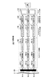
図6は、上記の本実施形態の記録装置100によって記録が行われた磁気記録メディア2上のデータフォーマットの概念図である。
FIG. 6 is a conceptual diagram of a data format on the
トラック#1、トラック#2、トラック#3はそれぞれ、記録装置100のM(M=3)個の記録ヘッドによって磁気記録メディア2に記録されたトラックである。トラック#1、トラック#2、トラック#3にはそれぞれ、プリアンブル21(1),21(2),・・・とデータ22(1),22(2),・・・が記録されている。プリアンブル21(1)は、前述したように、データ22(1)を再生するために必要な情報として、再生信号に対するゲイン制御のための学習に用いられるゲイン制御パターン、ビット同期処理などに用いられる同期パターン、及び、複数の再生ヘッドと1ユニット分の複数のトラックとのトラック幅方向の位置関係に相当するチャネル行列を演算するために必要な分離パターンを含むものであり、プリアンブル21(2)も同様にデータ22(2)を再生するために必要な上記の各パターンを含むものである。
ここでM個のトラック#1、トラック#2、トラック#3それぞれの、M個のプリアンブル21とM個のデータ22とのまとまりが、データを再生するための信号処理の一単位としてのユニット53(1),53(2),・・・,53(E)である。また、M個のトラック#1、トラック#2、トラック#3のまとまりを、以降「ユニット構成トラック列」と呼ぶこととする。
Here, a
ユニット構成トラック列51には、複数のユニット53(1),53(2),・・・,53(E)がトラック方向に連続して配置されている。この実施形態では、トラック上でデータ22を挟んで連続する複数のプリアンブル21、例えば2つのプリアンブル21内の分離パターンの再生信号をもとに、チャネル推定演算によってそれぞれ求められた例えば2つのチャネル行列から、そのデータ22の区間内で可変のチャネル行列として、データ22の区間を分割した各区間にそれぞれ対応する複数のチャネル行列を推定することとしている。このため、M個のトラック#1、トラック#2、トラック#3それぞれの最後のデータ22(E)の後にもプリアンブル21(E+1)が追加されている。
In the unit
また、磁気記録メディア2には、S個のユニット構成トラック列51が互いに平行に配置され、隣接する各ユニット構成トラック列51の間にはガードバンド52と呼ばれる、何も記録されていない領域が設けられている。このガードバンド52の目的は、隣のユニット構成トラック列51のトラックが再生されないようにすることにある。なお、符号26はトラックの最後に設けられたマージンであり、ここには何も記載されていない。
In the
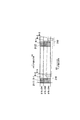
図7は、図6に示すフォーマット上での各再生ヘッドR−1,R−2,R−3のトラックずれの例を示す図である。 FIG. 7 is a diagram showing an example of the track shift of each of the reproducing heads R-1, R-2, R-3 on the format shown in FIG.
再生ヘッドR−1,R−2,R−3の移動方向を符号13の矢印方向とすると、各トラック#1,#2,#3からプリアンブルは、プリアンブル21(1)、プリアンブル21(2)の順で再生される。再生時に例えば外乱等によりトラッキングが不安定となった場合に、プリアンブル21(1)の位置では各再生ヘッドR−1,R−2,R−3と各トラック#1,#2,#3との位置関係が適正であったのが、プリアンブル21(2)の位置では適正な位置関係から逸脱してしまうことがある。図7の例では、プリアンブル21(2)の位置で、各再生ヘッドR−1,R−2,R−3と各トラック#1,#2,#3との位置関係は適正な状態から図中下方にトラック幅の50%ずれた状態を示している。このような場合、プリアンブル21(1)の再生信号に基いて得られた分離信号は、データ22(1)区間の後半部分において、品質が低下する。なお、ここでは再生ヘッドR−1,R−2,R−3が移動するものとして説明したが、再生ヘッドR−1,R−2,R−3が固定で、磁気記録メディア2が符号14の矢印方向に移動する場合も同様である。
Assuming that the moving direction of the reproducing heads R-1, R-2, and R-3 is the direction indicated by
そこで本実施形態では、データを挟んで連続する複数のプリアンブルの再生信号からそれぞれチャネル推定演算の結果として求められた複数のチャネル行列をもとに、そのデータの区間内で可変のチャネル行列を推定し、この可変のチャネル行列を用いて、1ユニット分の各再生ヘッドR−1,R−2,R−3の再生信号からトラックごとの再生信号を分離する処理を行うこととしている。 Therefore, in this embodiment, a variable channel matrix is estimated within a section of the data based on a plurality of channel matrices obtained as a result of channel estimation calculation from a plurality of consecutive preamble playback signals with data sandwiched therebetween. The variable channel matrix is used to separate the reproduction signal for each track from the reproduction signals of the reproduction heads R-1, R-2, and R-3 for one unit.
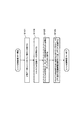
このチャネル行列の推定の動作を説明する前に、磁気記録メディア2に記録されるプリアンブル21の構成を説明する。
Before describing the operation of estimating the channel matrix, the configuration of the
図8は、磁気記録メディア2に記録されるプリアンブル21の構成を示す図である。
FIG. 8 is a diagram showing the configuration of the
同図に示すように、プリアンブル21は、第1のプリアンブル23、同期パターン24、及び第2のプリアンブル25で構成されている。トラック上では、先頭より、第1のプリアンブル23、同期パターン24、第2のプリアンブル25の順に配置される。第2のプリアンブル25の後にはデータ22が配置される。データ22は、記録時に図1の記録装置100の記録符号化部121−1,121−2,121−3で作成された記録符号列である。第1のプリアンブル23、同期パターン24、第2のプリアンブル25は、プリアンブル付加部131−1,131−2,131−3によって記録符号列に対して付加されたものである。
As shown in the figure, the
再生時において、第1のプリアンブル23は、図3に示した再生装置200の中のゲイン調整部224−1,224−2,224−3による再生アンプ221−1,221−2,221−3のゲイン制御のための学習信号として使用される。また、第1のプリアンブル23は、必要に応じて、同期信号検出器231にて、ビット同期検出のための学習や、再生信号のレベル調整等にも用いられる。
At the time of reproduction, the
同期パターン24は、同期信号検出器231によって第2のプリアンブル25の開始位置及びデータ22の開始位置を知るための情報として使用される。
The
第2のプリアンブル25は、再生時に複数の再生ヘッドR−1,R−2,R−3と1ユニット分の複数のトラック#1,#2,#3とのトラック幅方向における位置関係に相当するチャネル行列をチャネル推定演算部232にて求めるために使用されるパターンである。
The
第2のプリアンブル25は、トラック#1,#2,#3ごとに、隣りのトラックとの間で、トラック方向での位置が重ならないように配置された分離パターン31,32,33で構成される。すなわち、トラック#1の分離パターン31はT1区間に、トラック#2の分離パターン32はT2区間に、トラック#3の分離パターン33はT3区間にそれぞれ記録されている。これにより分離パターンの種類は、トラック数に対応する3種類となる。隣り合うトラックの分離パターン31,32,33どうしの間には所定の時間分の隙間34が設けられており、ユニット内で各トラック#1,#2,#3の各分離パターン31,32,33が重ならないようにしてある。
The
なお、分離パターン31,32,33は、最小記録波長と同等か、あるいはそれ以上の所定の記録波長で記録されたものである。
The
チャネル推定演算部232は、この分離パターン31,32,33の再生信号を用いてチャネル推定演算を行い、その結果としてチャネル行列を生成する。このチャネル行列は、1ユニット内の各トラック#1,#2,#3に対する個々の再生ヘッドR−1,R−2,R−3のトラック幅方向での位置情報に相当するもので、言い換えると、個々の再生ヘッドR−1,R−2,R−3がそれぞれ、ユニット内のどのトラックとどんな割合で位置的に重なるかを示した情報である。
The channel
次に、チャネル行列推定部233によるチャネル行列推定動作の詳細を説明する。なお、この詳細説明では、データ区間内で可変のチャネル行列の例として、データ区間を分割した各区間ごとのチャネル行列を採用することとする。
Next, details of the channel matrix estimation operation by the channel
チャネル行列推定部233は、チャネル推定演算部232によって、連続する複数のユニット、例えば2つのユニットのプリアンブル21内の分離パターンの再生信号をもとに、チャネル推定演算部232によってそれぞれ求められた2つのチャネル行列を用いて、その2つのプリアンブル21の間のデータ22の個々の分割区間に対応する複数のチャネル行列を推定する。
The
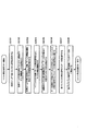
図9は、このチャネル行列推定部233によるチャネル行列推定動作の具体例を示す図である。
FIG. 9 is a diagram showing a specific example of the channel matrix estimation operation by the channel
この例では、2つのプリアンブル21(1),21(2)の間のデータ22(1)の区間をn分割する。ここではn=3とする。この場合、チャネル行列推定部233は、2つのプリアンブル21(1),21(2)内の分離パターンの再生信号からチャネル推定演算によってそれぞれ得られた2つのチャネル行列を用いて、例えば、直線補間などによって、データ22(1)の区間をn分割した各区間に対応するn個のチャネル行列を推定する。
In this example, the section of the data 22 (1) between the two preambles 21 (1) and 21 (2) is divided into n. Here, n = 3. In this case, the channel
この例において、チャネル行列を推定するための前提条件を示す。チャネル行列に用いられる値の最大値は1.0、最小値は0.0とする。例えば推定演算において、チャネル行列の値が0.0を下回る場合は0.0に固定し、1.0を上回る場合は1.0に固定する。また再生ヘッドR−1,R−2,R−3の幅はトラック幅の1.5倍とする。すなわち、再生ヘッドR−1,R−2,R−3の幅は、記録ヘッドW−1,W−2,W−3のヘッド幅の1.5倍とされ、個々の再生ヘッドR−1,R−2,R−3はそれぞれ複数のトラックから信号を再生できるものとする。図9の場合には、再生ヘッドR−1は、トラック#1とトラック#2から信号を再生し、再生ヘッドR−2は、3本のトラック#1,#2,#3から信号を再生し、再生ヘッドR−3はトラック#2とトラック#3から信号を再生する。
In this example, the preconditions for estimating the channel matrix are shown. The maximum value used for the channel matrix is 1.0, and the minimum value is 0.0. For example, in the estimation calculation, when the value of the channel matrix is less than 0.0, it is fixed to 0.0, and when it exceeds 1.0, it is fixed to 1.0. The widths of the reproducing heads R-1, R-2, and R-3 are 1.5 times the track width. That is, the width of the reproducing heads R-1, R-2, and R-3 is 1.5 times the head width of the recording heads W-1, W-2, and W-3, and the individual reproducing heads R-1 , R-2, and R-3 can reproduce signals from a plurality of tracks. In the case of FIG. 9, the reproducing head R-1 reproduces signals from the
チャネル行列推定部233は、まず、2つのプリアンブル21(1),21(2)内のそれぞれの分離パターンの再生信号から、チャネル推定演算によって求められた2つのチャネル行列34,35を比較し、最大差分及び正負変移方向を検出する。まず、最大差分と与えられた分割の数から、変移量を求める。次に、最大差分と与えられた分割の数から、変移量を求める。ここではn=3であって、かつ推定を行うのがT2区間のみであるから、最大差分の1/2倍の値を変位量とする。すなわち、最大差分が0.5であるため、変位量として0.25が得られる。そして変移量と変移方向をもとに、図9に示すチャネル行列36が、データ区間の中間であるT2区間に対応するチャネル行列として推定される。また、チャネル行列推定部233は、プリアンブル21(1)の再生信号からチャネル推定演算によって求められたチャネル行列34を、データ区間のT1区間に対するチャネル行列の推定結果とし、さらにプリアンブル21(2)の再生信号からチャネル推定演算によって求められたチャネル行列35を、データ区間のT3区間に対するチャネル行列の推定結果とする。
The channel
なお、ここではn=3としてT2区間を推定する場合とし、最大差分の1/2倍を変移量としたが、例えばn=4として、T1からT4の区間のうち、T2とT2の区間を推定とする場合は、最大差分の1/3倍を変移量とする。 In addition, here, it is assumed that the T2 section is estimated with n = 3, and ½ of the maximum difference is the transition amount. However, for example, when n = 4, the sections of T2 and T2 among the sections of T1 to T4 are selected. When estimating, 1/3 times the maximum difference is set as the shift amount.
信号分離演算部234による信号分離処理は、分割区間T1,T2,T3のそれぞれに対して推定された各チャネル行列を用いて、分割区間T1,T2,T3ごとに行われる。すなわち、信号分離演算部234は、T1区間ではプリアンブル21(1)の再生信号からチャネル推定演算によって求められたチャネル行列34を用いて信号分離処理を行い、T2区間ではチャネル行列推定部233により推定されたチャネル行列36を用いて信号分離処理を行い、T3区間ではプリアンブル21(2)の再生信号からチャネル推定演算によって求められたチャネル行列35を用いて信号分離処理を行う。
The signal separation processing by the signal
なお、信号分離演算部234による信号分離処理の演算方法としては、例えば、チャネル行列に対する一般化逆行列を求める方法などが挙げられる。このチャネル行列に対して一般化逆行列を求める方法は、一般に、ゼロ・フォーシング(Zero・Forcing)法と呼ばれる。但し、信号分離処理の方法はこれに限定されるものではなく、例えば、MMSE(Minimum Mean Squared Error)法を用いることもできる。
Note that examples of the calculation method of the signal separation processing by the signal
以上説明したように、本実施形態によれば、データを挟んで連続する複数のプリアンブルの再生信号からそれぞれチャネル推定演算の結果として求められた複数のチャネル行列をもとに、そのデータの区間内で可変のチャネル行列を推定し、この可変のチャネル行列を用いて、1ユニット分の各再生ヘッドR−1,R−2,R−3の再生信号からトラックごとの再生信号を分離する処理を行うことによって、各再生ヘッドと1ユニット分の各トラックとのトラック幅方向での位置関係が、外乱等によるトラックずれによって適正な状態から外れた場合においても、データ再生を良好に行うことが可能になる。 As described above, according to the present embodiment, based on a plurality of channel matrices respectively obtained as a result of channel estimation calculation from a plurality of preamble reproduced signals sandwiching data, within the section of the data. To estimate a variable channel matrix, and use this variable channel matrix to separate the reproduction signal for each track from the reproduction signal of each reproduction head R-1, R-2, R-3 for one unit. By doing so, even when the positional relationship in the track width direction between each reproducing head and each track for one unit deviates from an appropriate state due to a track shift due to a disturbance or the like, data reproduction can be performed satisfactorily. become.
なお、上記では、連続する2つのユニット内のプリアンブル内の分離パターンの再生信号をもとにチャネル推定演算によって求められた2つのチャネル行列から、トラックずれの状況を反映した、データ区間で可変のチャネル行列を推定することとしたが、連続する3つ以上のユニット内のプリアンブル内の分離パターンの再生信号をもとにチャネル推定演算によって求められた3つ以上のチャネル行列から、各々のデータ区間ごとに可変のチャネル行列を推定して、信号分離処理に用いるようにしてもよい。さらに、複数の参照するプリアンブルは、必ずしも連続していなくても良く、チャネル推定演算が行うための情報が得られることが出来れば良い。また、チャネル行列推定部233によるチャネル行列の補間方法としては、直線補間以外の手法を用いても構わない。
Note that, in the above, it is variable in the data section reflecting the situation of the track deviation from the two channel matrices obtained by the channel estimation calculation based on the reproduction signal of the separation pattern in the preamble in the two consecutive units. Although the channel matrix is estimated, each data section is obtained from three or more channel matrices obtained by channel estimation calculation based on a reproduction signal of a separation pattern in a preamble in three or more consecutive units. A variable channel matrix may be estimated every time and used for signal separation processing. Furthermore, the plurality of preambles to be referred to do not necessarily have to be continuous, and it is sufficient that information for performing channel estimation calculation can be obtained. Further, as a channel matrix interpolation method by the channel
また、図9では、各チャネル行列34,35,36が適用される分割区間T1,T2,T3の長さは均等としたが、各チャネル行列34,35,36がそれぞれ適用される分割区間の長さは均等である必要はない。例えば、図10に示すように、データ区間を均等に4分割して、T1区間では最初のプリアンブル21(1)内の分離パターンの再生信号より得られたチャネル行列34を用いて信号分離処理を行い、T2区間とT3区間では、2つのチャネル行列34,35からチャネル行列推定部233により補間されたチャネル行列36を用いて信号分離処理を行い、T4区間ではプリアンブル21(2)内の分離パターンの再生信号より得られたチャネル行列35を用いて分離処理を行うようにしてもよい。
In FIG. 9, the lengths of the divided sections T1, T2, and T3 to which the
また、データ区間を均等に5分割して、T2区間からT4区間でチャネル行列推定部233により補間されたチャネル行列36を用いて信号分離処理を行うようにしたり、データ区間を均等に7分割して、T3区間からT5区間でチャネル行列推定部233により補間されたチャネル行列36を用いて信号分離処理を行うようにしてもよい。その他の数にデータ区間を分割した場合も同様である。
Further, the data section is equally divided into five, and signal separation processing is performed using the
さらに、データ区間の均等に2分割し、T1区間ではプリアンブル21(1)内の分離パターンの再生信号より得られたチャネル行列34を用いて信号分離処理を行い、T2区間ではプリアンブル21(2)内の分離パターンの再生信号より得られたチャネル行列35を用いて信号分離処理を行うようにしてもよい。この方式では、チャネル行列推定部233によるチャネル行列36の補間は不要である。
Further, the data section is equally divided into two, and in the T1 section, signal separation processing is performed using the
さらに、データ区間の分割数nを1として、プリアンブル21(1)内の分離パターンの再生信号より得られたチャネル行列34とプリアンブル21(2)内の分離パターンの再生信号より得られたチャネル行列35とを所定の条件で選択して分離処理を行うようにしても構わない。この場合も、チャネル行列推定部233によるチャネル行列36の補間は不要である。
Further, assuming that the division number n of the data section is 1, the
本発明は、所定の複数のチャネル行列から、そのシステム及びその時の状況に適したチャネル行列を再生成し、これを用いることによって、よりデータ再生を良好に行うものである。 The present invention regenerates a channel matrix suitable for the system and the situation at that time from a predetermined plurality of channel matrices, and uses this to reproduce data more satisfactorily.
なお、本発明において、プリアンブル21の構成は図8に示したものに限定されるものではなく、チャネル行列の演算に使用できるものであれば何でもよい。
In the present invention, the configuration of the
図11は、本発明に係るデータフォーマットの別の例を示す図である。先に説明した図6のデータフォーマットでは、データ22(1)を挟んで連続する2つのプリアンブル21(1),21(2)内の分離パターンの再生信号からチャネル推定演算によってそれぞれ得られた2のチャネル行列を用いて、データ22(1)の区間内で可変のチャネル行列を推定することとしたが、例えば、データ22(2)よりも前方に配置された複数のプリアンブル、例えば、2つのプリアンブル21(1),21(2)内の分離パターンの再生信号からチャネル推定演算によって得られた2つのチャネル行列を用いて、データ22(2)の区間内で可変のチャネル行列を推定することによっても同様の効果を期待できる。このような場合には、図6に示した最後のデータ22(E)の後のプリアンブル21(E+1)は不要である。なお、この場合には、プリアンブル21とデータ22の再生信号を信号分離処理部230の記憶部内に記憶していなくても信号分離処理を行うことが可能である。
FIG. 11 is a diagram showing another example of the data format according to the present invention. In the data format of FIG. 6 described above, 2 obtained respectively by channel estimation calculation from the reproduction signals of the separated patterns in two preambles 21 (1) and 21 (2) that are continuous across the data 22 (1). The variable channel matrix is estimated within the section of the data 22 (1) using the channel matrix of, for example, a plurality of preambles arranged in front of the data 22 (2), for example, two Estimating a variable channel matrix within the section of data 22 (2) using two channel matrices obtained by channel estimation calculation from the reproduced signals of the separated patterns in preambles 21 (1) and 21 (2). The same effect can be expected. In such a case, the preamble 21 (E + 1) after the last data 22 (E) shown in FIG. 6 is not necessary. In this case, signal separation processing can be performed even if the reproduction signals of the
また、各再生ヘッドR−1,R−2,R−3と1ユニット分の複数のトラックとの再生時のトラック幅方向の位置関係を検出するために必要なパターンとして、上記の実施形態では、図8に示したような分離パターンを用いたが、本発明はこれに限定されるものではなく、例えば、トラッキングサーボ情報などを用いることも可能である。この場合には、トラッキングサーボ情報の各記録パターンと各再生ヘッドとの位置関係をユニット単位にまとめたものがチャネル推定情報として生成される。 Further, in the above embodiment, as a pattern necessary for detecting the positional relationship in the track width direction at the time of reproduction between each reproduction head R-1, R-2, R-3 and a plurality of tracks for one unit, Although the separation pattern as shown in FIG. 8 is used, the present invention is not limited to this, and for example, tracking servo information or the like can be used. In this case, a summary of the positional relationship between each recording pattern of the tracking servo information and each reproducing head in units is generated as channel estimation information.
また、分離パターンを用いて上記の位置関係を検出する手段と、トラッキングサーボ情報を用いて位置関係を検出する手段の両方を併用して、チャネル推定演算を行ってもよい。 Further, the channel estimation calculation may be performed using both the means for detecting the positional relationship using the separation pattern and the means for detecting the positional relationship using the tracking servo information.
さらに、上記の実施形態では、3行3列の行列をチャネル推定情報として算出する場合を説明したが、例えば、4行4列の行列や、その他の正方行列であっても、その一般化逆行列を求めることによって信号分離処理を行うことが可能である。さらに、正方行列以外の行列でも、同様にしてその一般化逆行列を求めるようにすればよい。 Furthermore, in the above-described embodiment, a case where a 3 × 3 matrix is calculated as channel estimation information has been described. However, for example, a 4 × 4 matrix or other square matrix may be generalized inversely. It is possible to perform signal separation processing by obtaining a matrix. Furthermore, a generalized inverse matrix may be obtained in the same manner for a matrix other than a square matrix.
なお、行列の一般化逆行列を求められるようにするために、分離パターンの種類はトラック数に対応させておく必要がある。 Note that the type of separation pattern needs to correspond to the number of tracks in order to obtain a generalized inverse matrix.
また、分離パターンは、互いに一次独立なトラック数のパターンとする。例えば、記録ヘッドの数を3、再生ヘッドの数を4とした場合、すなわち、記録トラックの数を3とし、再生信号の数を4とした場合は、分離パターンは、互いに一次独立な3通りのパターンで構成されるものとする。 The separation pattern is a pattern having the number of tracks that are primary independent of each other. For example, when the number of recording heads is 3 and the number of reproducing heads is 4, that is, when the number of recording tracks is 3 and the number of reproducing signals is 4, there are three types of separation patterns that are primarily independent of each other. It is assumed to be composed of the following pattern.
第1のプリアンブル23に配置されているゲイン制御パターンを、同期パターン24の後方に追加配置することによって、ゲイン制御のための情報量を増やしてもよい。
The amount of information for gain control may be increased by additionally arranging the gain control pattern arranged in the
第1のプリアンブル23に配置されているゲイン制御パターンと、第2のプリアンブル25に配置されている分離パターンとには、同一のパターンを採用してもかまわない。
The same pattern may be adopted as the gain control pattern arranged in the
上記の実施形態では、時間軸上で直交する分離パターンを用いたが、本発明はこれに限定されるものではなく、例えば、周波数軸上で直交するような分離パターン、あるいは、直交符号を用いた分離パターンなどを用いてもよい。 In the above embodiment, the separation pattern orthogonal to the time axis is used. However, the present invention is not limited to this. For example, a separation pattern orthogonal to the frequency axis or an orthogonal code is used. A separated pattern may be used.
(第2の実施形態) (Second Embodiment)
次に、本発明の第2の実施形態として、シングルヘッドを用いた磁気記録再生方式を説明する。 Next, a magnetic recording / reproducing system using a single head will be described as a second embodiment of the present invention.
この実施形態の磁気記録再生方式は、1個、又はユニット当たりのトラック数より少ない個数の記録ヘッド及び再生ヘッドを有し、トラックごとに記録位置を揃えることなく記録されている記録媒体を、トラックごとに再生位置を揃えることなく再生する方式である。 The magnetic recording / reproducing system of this embodiment has a recording head and a reproducing head whose number is less than the number of tracks per unit or a unit, and a recording medium on which recording is performed without aligning the recording position for each track. This is a method of reproducing without arranging the reproduction position every time.
図12は本発明の第2の実施形態である磁気記録再生方式における記録装置300の構成を示す図である。 FIG. 12 is a diagram showing a configuration of a recording apparatus 300 in the magnetic recording / reproducing system according to the second embodiment of the present invention.
この記録装置300は、シングルヘッドでユニットの記録を行うものである。ここで、一つの記録ヘッドによってユニットの記録を行う所定の回数をMとし、また一つの再生ヘッドによってユニットの再生を行う所定の回数をNとし、この実施形態では、M=3、N=3とする。 The recording apparatus 300 performs unit recording with a single head. Here, the predetermined number of times that the unit is recorded by one recording head is M, and the predetermined number of times that the unit is reproduced by one reproducing head is N. In this embodiment, M = 3 and N = 3. And
同図に示すように、この記録装置300は、マルチトラック化部110、マルチトラック記録符号化部120、マルチトラックプリアンブル付加部130、マルチトラック記録部140、記録ヘッドアレイ150で構成される。
As shown in the figure, the recording apparatus 300 includes a
マルチトラック記録符号化部120は、データ分配器111にてM個に振り分けられた記録データを符号化するM個の記録符号化部121−1,121−2,121−3で構成される。
The multitrack
マルチトラックプリアンブル付加部130は、マルチトラック記録符号化部120によって符号化された各記録データに、トラックごとに特定のプリアンブルを付加するM個のプリアンブル付加部131−1,131−2,131−3で構成される。
The multitrack
マルチトラック記録部140は、少なくとも1ユニット分の記録データを記憶する記憶部149と、プリアンブルが付加された記録符号列に所望のタイミングを与える1個の出力タイミング設定部141と、記録補償処理を行う1個の記録補償部144と、記録補償処理後の記録符号列をもとに記録ヘッドW−1を駆動する1個の記録アンプとで構成される。
The
図13は、この記録装置300のユニット記録時の動作の流れを示すフローチャートである。この記録装置300では、まず、入力された記録データ1がマルチトラック化部110にて、M(M=3)個のデータ(トラックごとのデータ)に分配される(ステップS301)。
FIG. 13 is a flowchart showing a flow of operations during unit recording of the recording apparatus 300. In the recording apparatus 300, first, the
分配された各データは、それぞれマルチトラック記録符号化部120の記録符号化部121−1,121−2,121−3にて、磁気記録メディア2の記録再生特性を考慮した符号列に符号化される。このとき符号列に、復調用同期パターンなどの、データ復調時に必要な情報も付加される(ステップS302)。
Each distributed data is encoded into a code string in consideration of recording / reproducing characteristics of the
次に、符号化されたそれぞれの記録データの所定の位置に、マルチトラックプリアンブル付加部130のプリアンブル付加部131−1,131−2,131−3にて、ユニット単位のデータの再生制御のために必要なパターンがプリアンブルとして付加され、記録符号列が得られる(ステップS303)。このようにしてプリアンブルが付加されたトラックごとの記録符号列は記憶部149に記憶される(ステップS304)。
Next, at a predetermined position of each encoded recording data, the preamble adding units 131-1, 131-2, and 131-3 of the multi-track
この後、記憶部149から、最初に記録するトラックの記録符号列が読み出され(ステップS305)、このトラックの記録符号列に対して出力タイミング設定部141によって所望のタイミングが与えられた後、記録補償部144にて、磁気記録メディア2への記録に最適化するための記録補償処理が施され、記録アンプ147にて電圧から電流に変換されて、記録ヘッドW−1によって磁気記録メディア2に記録される(ステップS306)。
Thereafter, the recording code string of the track to be recorded first is read from the storage unit 149 (step S305), and a desired timing is given to the recording code string of this track by the output
この後、1ユニット分のトラックの記録が終了したかどうかを判定し(ステップS307)、終了していなければ(ステップS307のNO)、記録ヘッドW−1を次の位置に移動させる(ステップS308)。この後、記憶部149から次のトラックの記録符号列を読み出して同様に記録のための処理を繰り返す。以上の動作を、1ユニット分のトラックの記録が終了するまで繰り返す。
Thereafter, it is determined whether or not the recording of one unit of track has been completed (step S307). If not completed (NO in step S307), the recording head W-1 is moved to the next position (step S308). ). Thereafter, the recording code string of the next track is read from the
そして、以上の磁気記録メディア2へのユニット単位の記録動作は、トラック方向に複数のユニットが連続して配置されるように繰り返される。
The above unit-unit recording operation on the
次に、この第2の実施形態の磁気記録再生方式における記録装置の変形例を示す。 Next, a modification of the recording apparatus in the magnetic recording / reproducing system of the second embodiment will be shown.
図14は、この第2の実施形態の磁気記録再生方式における記録装置の変形例である記録装置301の構成を示す図である。 FIG. 14 is a diagram showing a configuration of a recording apparatus 301 which is a modification of the recording apparatus in the magnetic recording / reproducing system of the second embodiment.
同図に示すように、この記録装置301は、所定の単位の記録データ、例えば所定のトラック数分の記録データを記録符号化する記録符号化部121と、トラックごとの符号化された記録データにトラックごとに特定のプリアンブルを付加するプリアンブル付加部131と、記憶部149と、プリアンブルが付加された記録符号列に所望のタイミングを与える出力タイミング設定部141と、記録補償処理を行う記録補償部144と、記録補償処理後の記録符号列をもとに記録ヘッドW−1を駆動する記録アンプ147とで構成されている。すなわち、図12に示す記録装置300の構成から、マルチトラック化部110(データ分配器111)が省かれているとともに、マルチトラック記録符号化部120は一つの記録符号化部121で構成され、マルチトラックプリアンブル付加部130は一つのプリアンブル付加部131で構成されている。
As shown in the figure, the recording apparatus 301 includes a
図15は、この記録装置301のユニット記録の動作の流れを示すフローチャートである。 FIG. 15 is a flowchart showing a unit recording operation flow of the recording apparatus 301.
この記録装置301では、まず、記録符号化部121にて、所定の単位の記録データ、例えば所定のトラック数分の記録データが、磁気記録メディア2の記録再生特性を考慮した符号列に符号化される。このときデータの符号列に、復調用同期パターンなどの、データ復調時に必要な情報も付加される(ステップS311)。
In this recording apparatus 301, first, recording data in a predetermined unit, for example, recording data for a predetermined number of tracks, is encoded into a code string in consideration of recording / reproduction characteristics of the
次に、符号化されたそれぞれの記録データの所定の位置に、プリアンブル付加部131にて、ユニット単位のデータを再生する制御のために必要なパターンがプリアンブルとして付加され、記録符号列が得られる(ステップS312)。このようにしてプリアンブル符号が付加されたトラックごとの記録符号列は記憶部149に記憶される(ステップS313)。
Next, a pattern necessary for control for reproducing data in units is added as a preamble to a predetermined position of each encoded recording data by the
この後、記憶部149から最初に記録するトラックの記録符号列が読み出され(ステップS314)、このトラックの記録符号列に対して出力タイミング設定部141によって所望のタイミングが与えられた後、記録補償部144にて、磁気記録メディア2への記録に最適化するための記録補償処理が施され、記録アンプ147にて電圧から電流に変換されて、記録ヘッドW−1によって磁気記録メディア2に記録される(ステップS315)。
Thereafter, the recording code string of the track to be recorded first is read from the storage unit 149 (step S314), and a desired timing is given to the recording code string of this track by the output
この後、1ユニット分のトラックの記録が終了したかどうかを判定し(ステップS316)、終了していなければ(ステップS316のNO)、記録ヘッドW−1を次の位置に移動させ(ステップS317)、記憶部149から次のトラックの記録符号列を読み出して同様に記録のための処理を繰り返す。以上の動作を、1ユニット分のトラックの記録が終了するまで繰り返す。
Thereafter, it is determined whether or not recording of one unit of track has been completed (step S316). If not completed (NO in step S316), the recording head W-1 is moved to the next position (step S317). ), The recording code string of the next track is read from the
そして、以上の磁気記録メディア2へのユニット単位の記録動作は、トラック方向に複数のユニットが連続して配置されるように繰り返される。
The above unit-unit recording operation on the
次に、本発明の第2の実施形態である磁気記録再生方式における再生装置について説明する。 Next, a reproducing apparatus in the magnetic recording / reproducing system according to the second embodiment of the present invention will be described.
図16は本発明の第2の実施形態である磁気記録再生方式における再生装置400の構成を示す図である。 FIG. 16 is a diagram showing a configuration of a reproducing apparatus 400 in the magnetic recording / reproducing system according to the second embodiment of the present invention.
同図に示すように、この再生装置400は、再生ヘッドアレイ210、チャネル再生部220、信号分離処理部230、マルチトラック復調部240、及び復元部260を備える。
As shown in the figure, the reproducing apparatus 400 includes a reproducing
再生ヘッドアレイ210は、磁気記録メディア2に記録された各トラックから信号を読み出す1個の再生ヘッドR−1を有する。
The reproducing
チャネル再生部220は、再生ヘッドアレイ210に搭載された再生ヘッドR−1によって再生された信号を増幅する1個の再生アンプ221と、再生アンプ221の出力の振幅レベルが所定の値になるようにゲインを制御する1個のゲイン調整部224と、ゲイン調整部224の出力を所定のビット幅のディジタル値に量子化する1個のA/Dコンバータ225とを備える。
The
信号分離処理部230は、A/Dコンバータ225の出力から同期パターンの検出を行う同期信号検出器231と、同期信号検出器231によって検出された同期パターンをもとに分離パターンの開始位置を特定して、この分離パターンの再生信号を用いてチャネル推定演算を行うチャネル推定演算部232と、データを挟んで連続する複数のプリアンブルの再生信号からチャネル推定演算によってそれぞれ求められた複数のチャネル行列を用いて、データの区間内で可変のチャネル行列を推定するチャネル行列推定部233と、チャネル行列推定部233によって推定された、データの区間内で可変のチャネル行列を用いて、各再生ヘッドR−1によって再生された1ユニット分の再生信号から、トラックごとの再生信号を分離する信号分離演算部234と、同期信号検出器231と信号分離演算部234との間に配置され、少なくとも1ユニット分の再生信号を記憶する記憶部235とを有している。
The signal
マルチトラック復調部240は、図4に示したように、信号分離演算部234にて分離されたトラックごとの再生信号に対して等化処理を行うM個の等化器241−1,241−2,241−3と、等化器241−1,241−2,241−3の出力からビット同期を行うM個のPLL242−1,242−2,242−3と、PLL242−1,242−2,242−3で生成されたビット同期信号を用いて各トラックごとの再生信号を二値化して符号列を生成する、たとえばビタビ検出器などM個の検出器243−1,243−2,243−3と、検出器243−1,243−2,243−3の出力である2値化された再生信号から符号列上の同期パターンを検出するM個の同期信号検出器244−1,244−2,244−3と、同期信号検出器244−1,244−2,244−3により検出された同期パターンをもとにデータの開始位置を特定して符号列からデータ列を復号するM個の復号器245−1,245−2,245−3とを備える。なお、マルチトラック復調部240は、上記の処理を行うために必要なデータ等の情報を記憶する、図示しない記憶部を有している。
As shown in FIG. 4, the
図16に戻って、復元部260は、マルチトラック復調部240内のM個の復号器245−1,245−2,245−3より出力された各トラックのデータを、記録時と逆の動作により連結して再生データ3を復元するデータ結合器261を備える。
Returning to FIG. 16, the
なお、シングルヘッドによる再生時のトラックのトレースは、少なくとも1ユニットの記録トラック数の回数だけ繰り返される。すなわち、トラック数以上の回数トレースを繰り返してもよい。その際、1ユニット分の全てのトラックが少なくとも1回はトレースされるようにする。記憶部235には、再生ヘッドR−1が移動した各位置で再生したユニット分の信号、すなわち再生ヘッドR−1が各位置で複数のトラックからそれぞれ再生した信号であり、同期信号検出器231によって分離パターン以降の必要な再生信号が記憶される。
Note that the track tracing during reproduction by the single head is repeated at least as many times as the number of recording tracks of one unit. That is, the tracing may be repeated more times than the number of tracks. At that time, all tracks for one unit are traced at least once. In the
図17は、この再生装置400のユニット再生動作を示すフローチャートである。 FIG. 17 is a flowchart showing the unit reproduction operation of the reproduction apparatus 400.
この再生装置400では、まず、再生ヘッドR−1によって、最初の位置で複数のトラックから信号が再生される(ステップS401)。次に、ゲイン調整部224にて、再生アンプ221の出力の振幅レベルが調整された後、その出力はA/Dコンバータ225にてディジタル値に変換されて同期信号検出器231に出力される(ステップS402)。
In the reproducing apparatus 400, first, signals are reproduced from a plurality of tracks at the initial position by the reproducing head R-1 (step S401). Next, after the amplitude level of the output of the
同期信号検出器231では、A/Dコンバータ225の出力から分離パターンの開始位置を知るための同期パターンの検出が行われた後(ステップS403)、トラックの再生信号は記憶部235に記憶される(ステップS404)。
The
次に、1ユニット分の再生信号が記憶部235に記憶されたかどうかを判断し(ステップS405)、1ユニット分の再生信号が記憶部235にまだ記憶されていない場合には、
Next, it is determined whether or not the reproduction signal for one unit is stored in the storage unit 235 (step S405), and when the reproduction signal for one unit is not yet stored in the
再生ヘッドR−1をトラック幅方向の次の位置にずらし(ステップ406)、ステップS401からステップS405までの動作を繰り返す。 The reproducing head R-1 is shifted to the next position in the track width direction (step 406), and the operations from step S401 to step S405 are repeated.
1ユニット分の再生信号が記憶部235に記憶された場合、チャネル推定演算部232は、記憶部235に記憶された1ユニット分の再生信号を読み出し、その再生信号に配置されている同期パターンをもとに分離パターンの開始位置を特定してその分離パターンの再生信号を用いてチャネル推定演算を行う(ステップS407)。
When the reproduction signal for one unit is stored in the
この後、チャネル行列推定部233は、トラック上でデータを挟んで連続する複数のプリアンブル中の分離パターンの再生信号からチャネル推定演算によって求められた複数のチャネル行列を用いて、そのデータの区間内で可変のチャネル行列を推定する(ステップS408)。
Thereafter, the channel
次に、信号分離演算部234は、記憶部235から1ユニット分の再生信号を読み出し、チャネル行列推定部233によって推定された、データの区間内で可変のチャネル行列をもとに、1ユニット分の再生信号から、トラックごとの再生信号を分離する(ステップS410)。
Next, the signal
この後は、トラックごとに分離された再生信号からマルチトラック復調部240にてデータ列の復号が行われ(ステップS411)、復元部260にて各トラックごとのデータが連結されて再生データ3が得られる(ステップS412)。
Thereafter, the
なお、A/Dコンバータ225の直前には必要に応じて不要な高域成分を除去するローパス・フィルタが備えられていてもよい。また、ゲイン調整部224については、A/Dコンバータ225の後段に接続して量子化後にゲインを制御するようにしてもよい。これは、A/Dコンバータ225のビット幅をより有効に用いたり、ゲイン調整部224の構成を、プリアンプルに含まれる各パターンの検出を考慮した簡単なものとしたい場合に有効である。あるいは、同期信号検出器231において利得目標値との誤差をとった情報を用いてゲイン調整部224においてゲイン調整を行うようにしてもよい。
Note that a low-pass filter that removes unnecessary high-frequency components may be provided immediately before the A /
また、マルチトラック復調部240にて、トラックごとの出力タイミングを制御しながら復調処理を行うようにすれば、復元部260でのデータの連結処理は不要となる。したがって、この場合には復元部260は不要である。
Further, if the
以上の実施形態では、図6に示したように、磁気記録メディア2のトラック方向に複数のユニット53(1),53(2),・・・,53(E)を配置した。このため、シングルヘッドを用いた磁気記録再生方式でのデータの分配方法には次の二通りが考えられる。
In the above embodiment, as shown in FIG. 6, a plurality of units 53 (1), 53 (2),..., 53 (E) are arranged in the track direction of the
第1の方法は、トラック一本ごとにデータを埋めて行く方法であり、図6において、まず、トラック#1にユニット53(1),53(2),・・・,53(E)の順にデータを配した後、次のトラック#2にも同様にユニット53(1),53(2),・・・,53(E)の順にデータを配し、続いて次のトラック#3にも同様にユニット53(1),53(2),・・・,53(E)の順にデータを配する、という方法である。この場合、再生時に1ユニット分の再生信号から得られるトラックごとの再生信号は不連続のデータとなるので、連続記録再生期間のすべてのユニットのトラックごとの再生信号を得た後、各再生データを、分配方法に応じた方法で連結することで元の記録データが復元されることになる。
The first method is a method of filling data for each track. In FIG. 6, first, units 53 (1), 53 (2),. After the data is arranged in order, the data is arranged in the order of the units 53 (1), 53 (2),..., 53 (E) in the same manner for the
第2の方法は、まず、先頭のユニットより順にデータを埋めて行く方法であり、まず、トラック#1の先頭のユニット53(1)、トラック#2の先頭のユニット53(1)、トラック#3の先頭のユニット53(1)の順にデータを配した後、次に、トラック#1の2番目のユニット53(2)、トラック#2の2番目のユニット53(2)、トラック#3の2番目のユニット53(2)の順に、続いて同様にトラック#1の3番目のユニット53(3)、トラック#2の3番目のユニット53(3)、トラック#3の3番目のユニット53(3)の順にそれぞれデータを配して行く、という方法である。この方法によれば、再生時に1ユニット分の再生信号から得られるトラックごとの再生信号は連続するデータとなるので、連続記録再生期間のすべてのユニットのトラックごとの再生信号を得た後、各再生データを再生順に連結することで元の記録データが復元されることになる。
In the second method, data is first filled in order from the head unit. First, the head unit 53 (1) of the
本発明は、上記で説明したリニア記録方式、ノンアジマス記録方式の磁気記録再生に適用されることに限らず、ヘリカル記録方式、アジマス記録方式にも適用可能である。 The present invention is not limited to the linear recording system and non-azimuth recording system magnetic recording / reproduction described above, but can also be applied to a helical recording system and an azimuth recording system.
その具体例を以下に示す。 Specific examples are shown below.
図18は、複数の記録ヘッドW−1,W−2,W−3を用いて、ノンアジマス方式とヘリカル・スキャン方式で磁気記録メディア2に記録されるデータフォーマットの概念図である。ヘリカル・スキャン方式においても、トラック#1,トラック#2,トラック#3で構成されるユニット構成トラック列51の間にはガードバンド52が配置される。トラック#1,トラック#2,トラック#3に記録されるプリアンブル21は、例えば図8に示したものと同様でよい。このようなヘリカル・スキャン方式の磁気記録再生方式においても、本発明は適用可能であり、第1の実施形態の磁気記録再生方式における記録装置100及び再生装置200の構成を採用することができる。
FIG. 18 is a conceptual diagram of a data format recorded on the
図19は、複数の記録ヘッドW−1,W−2,W−3,W−4,W−5,W−6を用いて、ダブルアジマス方式とヘリカル・スキャン方式により記録媒体に記録されるデータフォーマットの概念図である。 In FIG. 19, recording is performed on a recording medium by a double azimuth method and a helical scan method using a plurality of recording heads W-1, W-2, W-3, W-4, W-5, and W-6. It is a conceptual diagram of a data format.
本例では、記録用と再生用のそれぞれに6つの記録ヘッドW−1,W−2,W−3,W−4,W−5,W−6が用いられている。これらの記録ヘッドのうち、連続する3つの記録ヘッドW−1,W−2,W−3と、残る連続する3つの記録ヘッドW−4,W−5,W−6とは、互いにトラックの磁化方向であるアジマス方向が異なるようにしてある。すなわち、トラック#1−#3とトラック#4−#6とはアジマス方向が異なる。これらのトラック#1−#6が、データを再生するための処理の一単位であるユニットを複数含むユニット構成トラック列51となる。なお、このダブルアジマスの場合においては、ガードバンドは不要である。
In this example, six recording heads W-1, W-2, W-3, W-4, W-5, and W-6 are used for recording and reproduction, respectively. Of these recording heads, the three consecutive recording heads W-1, W-2, and W-3 and the remaining three consecutive recording heads W-4, W-5, and W-6 are mutually connected to each other. The azimuth direction, which is the magnetization direction, is made different. That is, track # 1- # 3 and track # 4- # 6 have different azimuth directions. These
なお、この例では、トラック#1−#6のまとまりを、データを再生するための信号処理の一単位(ユニット)としているが、アジマス方向が同一である3つの連続するトラック(例えばトラック#1−#3、トラック#4−#6)を、それぞれ一つのユニットとして信号処理を行うようにしてもよい。
In this example, a group of
各トラック#1−#6に記録されるプリアンブルは、例えば図8に示したものと同様でよい。このようなダブルアジマス方式とヘリカル・スキャン方式の磁気記録再生方式においても、本発明は適用可能であり、第1の実施形態の磁気記録再生方式における記録装置100及び再生装置200の構成を採用することができる。 The preamble recorded on each track # 1- # 6 may be the same as that shown in FIG. 8, for example. The present invention can also be applied to such a magnetic recording / reproducing system of the double azimuth method and the helical scan method, and the configuration of the recording apparatus 100 and the reproducing apparatus 200 in the magnetic recording / reproducing system of the first embodiment is adopted. be able to.
なお、本発明は、上記実施の形態に示す構成のものに限定されるものではなく、請求項に記載した技術的範囲を逸脱しない範囲において種々に変更し変形することは勿論である。 It should be noted that the present invention is not limited to the configuration shown in the above-described embodiment, and it is needless to say that various changes and modifications can be made without departing from the technical scope described in the claims.
1 記録データ
2 磁気記録メディア
3 再生データ
21 プリアンブル
22 データ
31,32,33 チャネル行列
34,35,36 分離パターン
53 ユニット
100 記録装置
110 マルチトラック化部
111 データ分配器
120 マルチトラック記録符号化部
121−1,121−2,121−3 記録符号化部
130 マルチトラックプリアンブル付加部
131−1,131−2,131−3 プリアンブル付加部
140 マルチトラック記録部
141−1,141−2,141−3 出力タイミング設定部
144−1,144−2,144−3 記録補償部
147−1,147−2,147−3 記録アンプ
149 記憶部
150 記録ヘッドアレイ
200 再生装置
210 再生ヘッドアレイ
220 チャネル再生部
221−1,221−2,221−3 再生アンプ
224−1,224−2,224−3 ゲイン調整部
225−1,225−2,225−3 A/Dコンバータ
230 信号分離処理部
231 同期信号検出器
232 チャネル推定演算部
233 チャネル行列推定部
234 信号分離演算部
235 記憶部
240 マルチトラック復調部
241−1,241−2,241−3 等化器
243−1,243−2,243−3 検出器
244−1,244−2,244−3 同期信号検出器
245−1,245−2,245−3 復号器
260 復元部
261 データ結合器
R−1,R−2,R−3 再生ヘッド
W−1,W−2,W−3 記録ヘッド
DESCRIPTION OF SYMBOLS 1 Recording data 2 Magnetic recording medium 3 Reproduction data 21 Preamble 22 Data 31, 32, 33 Channel matrix 34, 35, 36 Separation pattern 53 Unit 100 Recording apparatus 110 Multitracking part 111 Data distributor 120 Multitrack recording encoding part 121 -1, 121-2, 121-3 Recording encoding unit 130 Multitrack preamble adding unit 131-1, 131-2, 131-3 Preamble adding unit 140 Multitrack recording unit 141-1, 141-2, 141-3 Output timing setting units 144-1, 144-2, 144-3 Recording compensation units 147-1, 147-2, 147-3 Recording amplifier 149 Storage unit 150 Recording head array 200 Playback device 210 Playback head array 220 Channel playback unit 221 -1, 221-2, 22 1-3 Playback Amplifiers 224-1, 224-2, 224-3 Gain Adjustment Units 225-1, 225-2, 225-3 A / D Converter 230 Signal Separation Processing Unit 231 Synchronization Signal Detector 232 Channel Estimation Calculation Unit 233 Channel matrix estimation unit 234 Signal separation calculation unit 235 Storage unit 240 Multitrack demodulation units 241-1, 241-2, 241-3 Equalizers 243-1, 243-2, 243-3 Detectors 244-1, 244- 2, 244-3 Sync signal detectors 245-1, 245-2, 245-3 Decoder 260 Restoration unit 261 Data combiner R-1, R-2, R-3 Reproducing head W-1, W-2, W-3 Recording head
Claims (21)
前記ユニットごとの前記パターンの再生信号をもとに、前記再生ヘッドと前記複数のトラックとの再生時のトラック幅方向の位置関係に相当するチャネル行列を演算するチャネル推定演算部と、
前記ユニット内の前記パターンの再生信号をもとに前記チャネル推定演算部にて求められたチャネル行列を用いて、前記データの区間内で可変のチャネル行列を推定するチャネル行列推定部と、
前記チャネル行列推定部により推定された可変のチャネル行列を用いて、前記再生ヘッドによって再生された前記1ユニット分の前記データの再生信号から、前記トラックごとの前記データの再生信号を分離する信号分離演算部と
を具備することを特徴とする再生装置。 There are a plurality of tracks, and for each of the tracks, a positional relationship in the track width direction between the data, a reproducing head capable of reproducing a signal across the one or more tracks, and the plurality of tracks is shown. A preamble including a pattern necessary for detection is recorded, and the data of the plurality of tracks and the unit as a unit of signal processing for reproducing the data of the preamble include a plurality of the units in the track direction. An apparatus for reproducing the data from a recording medium continuously recorded on the recording medium,
Based on the reproduction signal of the pattern for each unit, a channel estimation calculation unit that calculates a channel matrix corresponding to the positional relationship in the track width direction during reproduction between the reproduction head and the plurality of tracks;
A channel matrix estimator that estimates a variable channel matrix within a section of the data using a channel matrix obtained by the channel estimation calculator based on the reproduction signal of the pattern in the unit;
Signal separation for separating the reproduction signal of the data for each track from the reproduction signal of the data for one unit reproduced by the reproduction head, using the variable channel matrix estimated by the channel matrix estimation unit A playback device comprising: an arithmetic unit.
前記チャネル行列推定部は、連続する複数の前記ユニット内の前記パターンの再生信号をもとに前記チャネル推定演算部にて求められた複数のチャネル行列を用いて、前記データの区間内で可変のチャネル行列を推定することを特徴とする再生装置。 The playback apparatus according to claim 1,
The channel matrix estimator is variable within a section of the data using a plurality of channel matrices obtained by the channel estimation calculator based on reproduction signals of the pattern in a plurality of consecutive units. A reproduction apparatus characterized by estimating a channel matrix.
前記チャネル行列推定部は、連続する複数の前記ユニット内の前記パターンの再生信号をもとに前記チャネル推定演算部によってそれぞれ求められた複数のチャネル行列から、前記データの区間を分割した個々の区間にそれぞれ対応する複数のチャネル行列を推定し、
前記信号分離演算部は、前記チャネル行列推定部によって得られた前記複数のチャネル行列を用いて、前記個々の区間ごとに、前記再生ヘッドによって再生された前記1ユニット分の前記データの再生信号から、前記トラックごとの前記データの再生信号を分離することを特徴とする再生装置。 The playback apparatus according to claim 1,
The channel matrix estimation unit is configured to divide the sections of the data from a plurality of channel matrices respectively obtained by the channel estimation calculation unit based on reproduction signals of the pattern in the plurality of consecutive units. Estimate a plurality of channel matrices respectively corresponding to
The signal separation calculation unit uses the plurality of channel matrices obtained by the channel matrix estimation unit, from the reproduced signal of the data for the one unit reproduced by the reproducing head for each individual section. A reproduction apparatus for separating the reproduction signal of the data for each track.
前記チャネル行列推定部は、連続する複数の前記ユニット内の前記パターンの再生信号をもとに前記チャネル推定演算部によって求められた複数のチャネル行列から、直線補間によって、前記データの個々の区間にそれぞれ対応する複数のチャネル行列を推定することを特徴とする再生装置。 The playback apparatus according to claim 3, wherein
The channel matrix estimation unit is configured to apply linear interpolation to individual sections of the data from a plurality of channel matrices obtained by the channel estimation calculation unit based on reproduction signals of the pattern in a plurality of consecutive units. A reproduction apparatus characterized by estimating a plurality of corresponding channel matrices.
前記チャネル行列推定部は、連続する2つの前記ユニット内の前記パターンの再生信号をもとに前記チャネル推定演算部によって求められた2つのチャネル行列から、前記2つのユニット内の前記プリアンブルに挟まれたデータの区間内で可変のチャネル行列を推定することを特徴とする再生装置。 The playback apparatus according to claim 1,
The channel matrix estimation unit is sandwiched by the preambles in the two units from two channel matrices obtained by the channel estimation calculation unit based on the reproduced signals of the patterns in the two consecutive units. A reproduction apparatus characterized by estimating a variable channel matrix within a section of data.
前記チャネル行列推定部は、連続する複数の前記ユニット内の前記パターンの再生信号をもとに前記チャネル推定演算部によって求められた複数のチャネル行列から、前記複数のパターンの両方よりも後方に位置するデータの区間内で可変のチャネル行列を推定することを特徴とする再生装置。 The playback apparatus according to claim 1,
The channel matrix estimation unit is positioned behind both of the plurality of patterns from a plurality of channel matrices obtained by the channel estimation calculation unit based on reproduction signals of the patterns in the plurality of consecutive units. A reproduction apparatus characterized by estimating a variable channel matrix within a section of data to be transmitted.
前記パターンが、前記トラックごとにユニークな位置に配置された、最小記録波長と同等あるいはそれ以上の記録波長の信号からなる分離パターンであることを特徴とする再生装置。 The playback apparatus according to claim 1,
2. A reproducing apparatus according to claim 1, wherein the pattern is a separation pattern composed of a signal having a recording wavelength equal to or greater than the minimum recording wavelength and disposed at a unique position for each track.
前記パターンが、トラッキングサーボ情報であることを特徴とする再生装置。 The playback apparatus according to claim 1,
The reproducing apparatus, wherein the pattern is tracking servo information.
前記信号分離演算部は、前記チャネル行列推定部により推定された前記可変のチャネル行列の一般化逆行列を求め、この一般化逆行列と、前記再生ヘッドによって再生された前記1ユニット分の前記データの再生信号とから、前記トラックごとの前記データの再生信号を分離することを特徴とする再生装置。 The playback apparatus according to claim 1,
The signal separation calculation unit obtains a generalized inverse matrix of the variable channel matrix estimated by the channel matrix estimation unit, and the generalized inverse matrix and the data for the one unit reproduced by the reproduction head A reproduction apparatus for separating the reproduction signal of the data for each track from the reproduction signal.
前記信号分離演算部は、前記チャネル行列推定部により推定された可変のチャネル行列に対して、MMSE(Minimum Mean Squared Error)法により、前記トラックごとの前記データの再生信号を分離することを特徴とする再生装置。 The playback apparatus according to claim 1,
The signal separation operation unit separates a reproduction signal of the data for each track by a MMSE (Minimum Mean Squared Error) method from the variable channel matrix estimated by the channel matrix estimation unit. Playback device.
前記1ユニット分の複数のトラックに対してそれぞれ異なる位置関係で信号を再生可能なように、前記再生ヘッドを複数備えることを特徴とする再生装置。 The playback apparatus according to claim 1,
A reproducing apparatus comprising a plurality of reproducing heads so that signals can be reproduced with different positional relationships with respect to the plurality of tracks of one unit.
前記1ユニット分の複数のトラックに対してそれぞれ異なる位置関係で信号を再生可能なように、前記再生ヘッドは前記トラックの幅方向に移動可能であることを特徴とする再生装置。 The playback apparatus according to claim 1,
The reproducing apparatus is characterized in that the reproducing head is movable in the width direction of the track so that signals can be reproduced in different positional relations with respect to the plurality of tracks of one unit.
前記ユニットごとの前記パターンの再生信号をもとに、前記再生ヘッドと前記複数のトラックとの再生時のトラック幅方向の位置関係に相当するチャネル行列を演算するステップと、
連続する複数の前記ユニット内の前記パターンの再生信号をもとに前記チャネル行列演算ステップにてそれぞれ求められた複数のチャネル行列を用いて、前記データの区間内で可変のチャネル行列を推定するステップと、
前記推定された可変のチャネル行列を用いて、前記再生ヘッドによって再生された前記1ユニット分の前記データの再生信号から、前記トラックごとの前記データの再生信号を分離するステップと
を具備することを特徴とする再生方法。 There are a plurality of tracks, and for each of the tracks, a positional relationship in the track width direction between the data, a reproducing head capable of reproducing a signal across the one or more tracks, and the plurality of tracks is shown. A preamble including a pattern necessary for detection is recorded, and a plurality of units are arranged in the track direction as a unit that is a unit of signal processing for reproducing the data and the preamble of the plurality of tracks. A method for reproducing the data from a continuously recorded recording medium,
Calculating a channel matrix corresponding to the positional relationship in the track width direction during reproduction between the reproduction head and the plurality of tracks, based on the reproduction signal of the pattern for each unit;
A step of estimating a variable channel matrix within a section of the data by using a plurality of channel matrices respectively obtained in the channel matrix calculation step based on reproduction signals of the pattern in a plurality of consecutive units. When,
Separating the reproduction signal of the data for each track from the reproduction signal of the data for the unit reproduced by the reproduction head using the estimated variable channel matrix. A characteristic reproduction method.
前記トラックごとに記録すべきデータを符号化するマルチトラック記録符号化部と、
前記マルチトラック記録符号化部により符号化された前記トラックごとの前記データの符号列にそれぞれ、1以上の前記トラックに跨って信号を再生することが可能な再生ヘッドと前記複数のトラックとの再生時のトラック幅方向の位置関係を検出するために必要なパターンを含むプリアンブルを付加するマルチトラックプリアンブル付加部と、
前記複数のトラックの前記プリアンブル及び前記データを、前記データを再生するための信号処理の一単位であるユニットとして、このユニットが前記トラック方向に複数配置されるように、前記マルチトラックプリアンブル付加部によって前記プリアンブルが付加された前記トラックごとのデータを前記記録ヘッドにより前記記録媒体に記録するマルチトラック記録部と
を具備することを特徴とする記録装置。 An apparatus for recording a plurality of tracks on a recording medium,
A multi-track recording encoding unit for encoding data to be recorded for each track;
Reproduction of a reproduction head capable of reproducing a signal across one or more of the tracks in the code string of the data for each of the tracks encoded by the multitrack recording encoding unit and the plurality of tracks A multi-track preamble adding unit for adding a preamble including a pattern necessary for detecting the positional relationship in the track width direction at the time;
The multi-track preamble adding unit sets the preamble and the data of the plurality of tracks as a unit that is a unit of signal processing for reproducing the data so that a plurality of the units are arranged in the track direction. A recording apparatus comprising: a multi-track recording unit that records data for each track to which the preamble is added to the recording medium by the recording head.
前記マルチトラックプリアンブル付加部は、前記トラックの最後に記録される前記データ以外のデータに対してはこのデータの前に前記プリアンブルを付加し、前記トラックの最後に記録される前記データに対してはこのデータの前後に前記プリアンブルを付加することを特徴とする記録装置。 15. The recording apparatus according to claim 14, wherein
The multi-track preamble adding unit adds the preamble to the data other than the data recorded at the end of the track, and adds the preamble to the data recorded at the end of the track. A recording apparatus, wherein the preamble is added before and after the data.
前記トラックごとに記録すべきデータを符号化するステップと、
前記符号化された前記トラックごとの前記データの符号列にそれぞれ、1以上の前記トラックに跨って信号を再生することが可能な再生ヘッドと前記複数のトラックとの再生時のトラック幅方向の位置関係を検出するために必要なパターンを含むプリアンブルを付加するステップと、
前記複数のトラックの前記プリアンブル及び前記データを、前記データを再生するための信号処理の一単位であるユニットとして、このユニットが前記トラック方向に複数配置されるように、前記プリアンブルが付加された前記トラックごとのデータを前記記録ヘッドにより前記記録媒体に記録するステップと
を具備することを特徴とする記録方法。 A method for recording a plurality of tracks on a recording medium,
Encoding data to be recorded for each track;
A position in the track width direction during reproduction of the reproduction head capable of reproducing a signal across one or more of the tracks and the plurality of tracks in the encoded code string of the data for each of the tracks. Adding a preamble containing the pattern necessary to detect the relationship;
The preamble and the data of the plurality of tracks as a unit that is a unit of signal processing for reproducing the data, and the preamble is added so that a plurality of the units are arranged in the track direction. Recording the data for each track on the recording medium by the recording head.
前記データの前後に前記プリアンブルが配置されていることを特徴とするデータフォーマット。 The data format according to claim 17, wherein
A data format, wherein the preamble is arranged before and after the data.
前記データの符号列の前後に前記プリアンブルが記録されていることを特徴とする記録媒体。 The recording medium according to claim 19, wherein
The recording medium, wherein the preamble is recorded before and after the data code string.
前記トラックごとに記録すべきデータを符号化するマルチトラック記録符号化部と、
前記マルチトラック記録符号化部により符号化された前記トラックごとの前記データの符号列にそれぞれ、1以上の前記トラックに跨って信号を再生することが可能な再生ヘッドと前記複数のトラックとの再生時のトラック幅方向の位置関係を検出するために必要なパターンを含むプリアンブルを付加するマルチトラックプリアンブル付加部と、
前記複数のトラックの前記プリアンブル及び前記データを、前記データを再生するための信号処理の一単位であるユニットとして、このユニットが前記トラック方向に複数配置されるように、前記マルチトラックプリアンブル付加部によって前記プリアンブルが付加された前記トラックごとのデータを前記記録ヘッドにより前記記録媒体に記録するマルチトラック記録部と
を具備する記録装置と、
前記記録媒体から前記データを再生する装置であって、
前記ユニットごとの前記パターンの再生信号をもとに、前記再生ヘッドと前記複数のトラックとの再生時のトラック幅方向の位置関係に相当するチャネル行列を演算するチャネル推定演算部と、
前記ユニット内の前記パターンの再生信号をもとに前記チャネル推定演算部にて求められたチャネル行列を用いて、前記データの区間内で可変のチャネル行列を推定するチャネル行列推定部と、
前記チャネル行列推定部により推定された可変のチャネル行列を用いて、前記再生ヘッドによって再生された前記1ユニット分の前記データの再生信号から、前記トラックごとの前記データの再生信号を分離する信号分離演算部と
を具備する再生装置と
を具備することを特徴とする記録再生装置。 An apparatus for recording a plurality of tracks on a recording medium,
A multi-track recording encoding unit for encoding data to be recorded for each track;
Reproduction of a reproduction head capable of reproducing a signal across one or more of the tracks in the code string of the data for each of the tracks encoded by the multitrack recording encoding unit and the plurality of tracks A multi-track preamble adding unit for adding a preamble including a pattern necessary for detecting the positional relationship in the track width direction at the time;
The multi-track preamble adding unit sets the preamble and the data of the plurality of tracks as a unit that is a unit of signal processing for reproducing the data so that a plurality of the units are arranged in the track direction. A recording apparatus comprising: a multi-track recording unit that records data for each track to which the preamble is added to the recording medium by the recording head;
An apparatus for reproducing the data from the recording medium,
Based on the reproduction signal of the pattern for each unit, a channel estimation calculation unit that calculates a channel matrix corresponding to the positional relationship in the track width direction during reproduction between the reproduction head and the plurality of tracks;
A channel matrix estimator that estimates a variable channel matrix within a section of the data using a channel matrix obtained by the channel estimation calculator based on the reproduction signal of the pattern in the unit;
Signal separation for separating the reproduction signal of the data for each track from the reproduction signal of the data for one unit reproduced by the reproduction head, using the variable channel matrix estimated by the channel matrix estimation unit A recording / reproducing apparatus comprising: a computing unit;
Priority Applications (1)
| Application Number | Priority Date | Filing Date | Title |
|---|---|---|---|
| JP2007127143A JP2008282501A (en) | 2007-05-11 | 2007-05-11 | Device and method for reproducing, device and method for recording, recording/reproducing device, data format, and recording medium |
Applications Claiming Priority (1)
| Application Number | Priority Date | Filing Date | Title |
|---|---|---|---|
| JP2007127143A JP2008282501A (en) | 2007-05-11 | 2007-05-11 | Device and method for reproducing, device and method for recording, recording/reproducing device, data format, and recording medium |
Publications (2)
| Publication Number | Publication Date |
|---|---|
| JP2008282501A true JP2008282501A (en) | 2008-11-20 |
| JP2008282501A5 JP2008282501A5 (en) | 2010-06-24 |
Family
ID=40143186
Family Applications (1)
| Application Number | Title | Priority Date | Filing Date |
|---|---|---|---|
| JP2007127143A Pending JP2008282501A (en) | 2007-05-11 | 2007-05-11 | Device and method for reproducing, device and method for recording, recording/reproducing device, data format, and recording medium |
Country Status (1)
| Country | Link |
|---|---|
| JP (1) | JP2008282501A (en) |
Cited By (6)
| Publication number | Priority date | Publication date | Assignee | Title |
|---|---|---|---|---|
| US10789981B2 (en) | 2018-05-07 | 2020-09-29 | Fujifilm Corporation | Magnetic tape reading apparatus and a magnetic tape reading method |
| US11017805B2 (en) | 2019-02-26 | 2021-05-25 | Fujifilm Corporation | Magnetic tape recording device having dual reading transducers |
| US11056141B2 (en) | 2019-01-31 | 2021-07-06 | Fujifilm Corporation | Magnetic tape, magnetic tape cartridge, and magnetic tape apparatus |
| US11437065B2 (en) | 2019-09-17 | 2022-09-06 | Fujifilm Corporation | Magnetic recording medium and magnetic recording and reproducing device |
| US11488628B2 (en) | 2018-07-27 | 2022-11-01 | Fujifilm Corporation | Magnetic tape, magnetic tape cartridge, and magnetic tape apparatus |
| US11495257B2 (en) | 2017-06-23 | 2022-11-08 | Fujifilm Corporation | Magnetic recording medium |
Citations (2)
| Publication number | Priority date | Publication date | Assignee | Title |
|---|---|---|---|---|
| JPS59112406A (en) * | 1982-12-17 | 1984-06-28 | Sony Corp | Recording and reproducing method of pcm signal |
| JP2001283532A (en) * | 2000-03-31 | 2001-10-12 | Sony Corp | Magnetic tape recorder and method for magnetic tape recording, format of magnetic tape, and recording medium |
-
2007
- 2007-05-11 JP JP2007127143A patent/JP2008282501A/en active Pending
Patent Citations (2)
| Publication number | Priority date | Publication date | Assignee | Title |
|---|---|---|---|---|
| JPS59112406A (en) * | 1982-12-17 | 1984-06-28 | Sony Corp | Recording and reproducing method of pcm signal |
| JP2001283532A (en) * | 2000-03-31 | 2001-10-12 | Sony Corp | Magnetic tape recorder and method for magnetic tape recording, format of magnetic tape, and recording medium |
Cited By (9)
| Publication number | Priority date | Publication date | Assignee | Title |
|---|---|---|---|---|
| US11495257B2 (en) | 2017-06-23 | 2022-11-08 | Fujifilm Corporation | Magnetic recording medium |
| US11545177B2 (en) | 2017-06-23 | 2023-01-03 | Fujifilm Corporation | Magnetic recording medium |
| US10789981B2 (en) | 2018-05-07 | 2020-09-29 | Fujifilm Corporation | Magnetic tape reading apparatus and a magnetic tape reading method |
| US11488628B2 (en) | 2018-07-27 | 2022-11-01 | Fujifilm Corporation | Magnetic tape, magnetic tape cartridge, and magnetic tape apparatus |
| US11670332B2 (en) | 2018-07-27 | 2023-06-06 | Fujifilm Corporation | Magnetic tape, magnetic tape cartridge, and magnetic tape apparatus |
| US11056141B2 (en) | 2019-01-31 | 2021-07-06 | Fujifilm Corporation | Magnetic tape, magnetic tape cartridge, and magnetic tape apparatus |
| US11430476B2 (en) | 2019-01-31 | 2022-08-30 | Fujifilm Corporation | Magnetic tape, magnetic tape cartridge, and magnetic tape apparatus |
| US11017805B2 (en) | 2019-02-26 | 2021-05-25 | Fujifilm Corporation | Magnetic tape recording device having dual reading transducers |
| US11437065B2 (en) | 2019-09-17 | 2022-09-06 | Fujifilm Corporation | Magnetic recording medium and magnetic recording and reproducing device |
Similar Documents
| Publication | Publication Date | Title |
|---|---|---|
| JP2009032338A (en) | Reproducing device, reproduction method, track format, recording medium, and recording and reproducing device | |
| US7636219B2 (en) | Magnetic recording and reproducing apparatus and magnetic recording and reproducing method | |
| JP2007265568A (en) | Magnetic recording and reproducing method, recording device, reproducing device, and magnetic recording media | |
| US4835627A (en) | Magnetic recorder/reproducer | |
| KR900000630B1 (en) | Method and apparatus for recording and reproducing a digital signal with a stationary head | |
| US20100007984A1 (en) | Recording medium, recording apparatus, reproducing apparatus, and reproducing method | |
| JP2008282501A (en) | Device and method for reproducing, device and method for recording, recording/reproducing device, data format, and recording medium | |
| JP4697012B2 (en) | Magnetic recording / reproducing apparatus and magnetic recording / reproducing method | |
| KR960002299A (en) | How to record and play back digital video tapes for trick play | |
| JP3797447B2 (en) | Information recording / reproducing device | |
| EP0437316B1 (en) | Digital signal recording method and digital signal recording and reproducing apparatus | |
| JP4941143B2 (en) | Data reproducing apparatus, data reproducing method, and data recording / reproducing apparatus | |
| JP5003327B2 (en) | Data format, recording medium, recording apparatus, recording method, reproducing apparatus, reproducing method, and recording / reproducing apparatus | |
| JP4983460B2 (en) | Data reproducing apparatus, data reproducing method, and data recording / reproducing apparatus | |
| JP2008282504A (en) | Device and method for reproducing data, and data recording/reproducing device | |
| JP4844490B2 (en) | Playback apparatus and playback method | |
| JP5045587B2 (en) | Recording medium and recording apparatus | |
| JP2009032373A (en) | Track format, recording medium, recording device, recording method, reproducing device, reproduction method, and recording and reproducing device | |
| JP5151754B2 (en) | Playback apparatus and playback method | |
| JP2008293558A (en) | Magnetic recording and reproducing device, recording apparatus, recording method, and magnetic recording medium | |
| JP2009037665A (en) | Reproduction device, method for reproduction, recording and reproducing device, track format, and recording medium | |
| JP2009032318A (en) | Magnetic recording and reproducing device, magnetic recording device, magnetic recording and reproducing method, magnetic recording media | |
| JP2009032375A (en) | Track format, recording medium, recording device, recording method, reproducing device, reproduction method, and recording and reproducing device | |
| JP2009032374A (en) | Recording device, recording method, recording and reproducing device, and recording and reproducing method | |
| KR100283144B1 (en) | Digital recording / playback device |
Legal Events
| Date | Code | Title | Description |
|---|---|---|---|
| A521 | Written amendment |
Free format text: JAPANESE INTERMEDIATE CODE: A523 Effective date: 20100506 |
|
| A621 | Written request for application examination |
Free format text: JAPANESE INTERMEDIATE CODE: A621 Effective date: 20100506 |
|
| A977 | Report on retrieval |
Free format text: JAPANESE INTERMEDIATE CODE: A971007 Effective date: 20110701 |
|
| A131 | Notification of reasons for refusal |
Free format text: JAPANESE INTERMEDIATE CODE: A131 Effective date: 20110802 |
|
| A521 | Written amendment |
Free format text: JAPANESE INTERMEDIATE CODE: A523 Effective date: 20110926 |
|
| A02 | Decision of refusal |
Free format text: JAPANESE INTERMEDIATE CODE: A02 Effective date: 20120522 |