JP4963387B2 - Portable device - Google Patents
Portable device Download PDFInfo
- Publication number
- JP4963387B2 JP4963387B2 JP2006245261A JP2006245261A JP4963387B2 JP 4963387 B2 JP4963387 B2 JP 4963387B2 JP 2006245261 A JP2006245261 A JP 2006245261A JP 2006245261 A JP2006245261 A JP 2006245261A JP 4963387 B2 JP4963387 B2 JP 4963387B2
- Authority
- JP
- Japan
- Prior art keywords
- lens barrel
- substrate
- portable device
- optical axis
- coil
- Prior art date
- Legal status (The legal status is an assumption and is not a legal conclusion. Google has not performed a legal analysis and makes no representation as to the accuracy of the status listed.)
- Active
Links
Images


Description
本発明は、画像の振れを補正する機能を有する携帯電話などの携帯機器に関するものである。 The present invention relates to a mobile device such as a mobile phone having a function of correcting image shake.
現在のカメラは露出決定やピント合わせ等の撮影にとって重要な作業は全て自動化され、カメラ操作に未熟な人でも撮影失敗を起こす可能性は非常に少なくなっている。また、最近では、カメラに加わる手振れによる画像の振れを防ぐ振れ補正装置も多くの製品に搭載されてきており、撮影者の撮影ミスを誘発する要因は殆ど無くなってきている。 With the current camera, all the important tasks for shooting such as determining exposure and focusing are automated, and it is very unlikely that people who are unskilled in camera operation will fail to shoot. Recently, many products have also been equipped with a shake correction device that prevents image shake due to camera shake applied to the camera, and there has been almost no cause for a photographer to make a shooting mistake.
ここで、振れ補正装置ついて簡単に説明する。撮影時のカメラの手振れは、周波数として通常1Hzないし10Hzの振動である。撮影時点において上記のような手振れを起こしていても像振れの無い写真を撮影可能とする為には、手振れによるカメラの振動を検出し、その検出値に応じて振れを相殺する方向にレンズを変位させる。その為、第1に、手振れを正確に検出し、第2に、手振れによる光軸変化を補正することが必要となる。 Here, the shake correction apparatus will be briefly described. The camera shake at the time of shooting is usually a vibration of 1 Hz to 10 Hz as a frequency. In order to be able to take a picture without image shake even when the above-mentioned camera shake occurs at the time of shooting, the camera shake due to camera shake is detected, and the lens is set in a direction to cancel the shake according to the detected value. Displace. For this reason, firstly, it is necessary to accurately detect camera shake, and secondly, it is necessary to correct an optical axis change due to camera shake.
手振れの検出は、原理的にいえば、加速度、角加速度、角速度、角変位等を検出し、振れ補正の為にその出力を適宜演算処理する手段をカメラに搭載することによって行う。そして、この検出情報に基づき、撮影光軸を偏心させる補正レンズを駆動させて像振れ抑制が行われる。 In principle, camera shake is detected by detecting acceleration, angular acceleration, angular velocity, angular displacement, and the like, and mounting a means for appropriately calculating the output for camera shake correction in the camera. Then, based on this detection information, image blur suppression is performed by driving a correction lens that decenters the photographic optical axis.
図12は振れ補正装置を有するデジタルコンパクトカメラの外観図であり、光軸120に対するカメラ縦振れ122p及び横振れ122yに対して振れ補正を行う。尚、カメラ本体121において、121aはレリーズボタン、121bはモードダイアル(メインスイッチを含む)、121cはリトラクタブルストロボである。
FIG. 12 is an external view of a digital compact camera having a shake correction device, and performs shake correction for the camera
図12ではカメラ本体121の背面に配置されて見えないが、カメラ本体121の背面には液晶モニターが設けられており、後述の撮像素子54で撮像される像を確認できるようになっている。撮影者は液晶モニターで撮影画像の構図を確認して、その後撮影を行う。
In FIG. 12, a liquid crystal monitor is provided on the back surface of the
図13は、図12の内部斜視図である。図13において、54は撮像手段である撮像素子、131は補正レンズ130を図中132p,132y方向に自在に駆動して矢印122p,122y方向の像振れ補正を行う補正機構である。21p,21yは各々矢印21a,21b回りの振れを検出する角速度計や角加速度計等の振動検出部である。振動検出部21p,21yの出力は演算部81p,81yを介して振れ補正の駆動目標値に変換され、補正機構131に入力され、該補正機構131にて振れ補正が行われる。
FIG. 13 is an internal perspective view of FIG. In FIG. 13,
ところで、最近のデジタルカメラにおいては、撮像素子は非常に小型になってきており、携帯電話にまで搭載されるようになってきている。そして、これまでも携帯電話に搭載することを目的とした提案が行われている。特許文献1では、撮影光学系と撮像手段である撮像素子の両者を一体にして基板に対して揺動させる構成になっている。特許文献2では、携帯電話用の像振れ補正装置として、振動検出部を振れ補正部の側面に貼り付け、振動検出部の出力が常にゼロになるように振れ補正部を制御している。
携帯電話は小さく、軽いので、撮影時の手振れが大きいという問題がある。そのため、手振れによる画像の振れ対策は重要な課題である。しかしながら、今までの振れ補正装置では、特に振れ補正手段が大きく、複雑である為に携帯電話に搭載することは難しい。上記特許文献1においては、撮影光学系と撮像素子の両者を一体にして基板に対して揺動させる構成になっているので、大型であり、且つ、撮像素子の基板に対する接続が駆動負荷になるという問題がある。 Since mobile phones are small and light, there is a problem that camera shake during shooting is large. Therefore, countermeasures against image blur due to camera shake are an important issue. However, in the conventional shake correction apparatus, the shake correction means is particularly large and complicated, so that it is difficult to mount it on a mobile phone. In the above-mentioned patent document 1, since both the photographing optical system and the image pickup device are integrally swung with respect to the substrate, the size is large, and the connection of the image pickup device to the substrate becomes a driving load. There is a problem.
また、上記特許文献2のような制御方法(ゼロメソッド)は、振動検出部の出力リニアリティ不足や温度変動に対して安定するというメリットがある。しかしながら、振れ補正部と振動検出部を一体にまとめる必要があるので、装置が大型化してしまう。像振れ補正装置の小型の為には、振動検出部と該振れ補正部を分散させて携帯機器の空いているスペースに配置することが好ましい。 Moreover, the control method (zero method) like the above-mentioned patent document 2 has the merit that it is stable against the output linearity deficiency of the vibration detection unit and the temperature fluctuation. However, since the shake correction unit and the vibration detection unit need to be integrated, the apparatus becomes large. In order to reduce the size of the image shake correction apparatus, it is preferable to disperse the vibration detection unit and the shake correction unit and arrange them in an empty space of the portable device.
(発明の目的)
本発明の目的は、像振れ補正機能を有しながら、小型化を達成することのできる携帯機器を提供しようとするものである。
(Object of invention)
An object of the present invention is to provide a portable device that can achieve downsizing while having an image blur correction function.
上記目的を達成するために、本発明は、撮像手段と、該撮像手段を保持する基板と、光軸方向に複数のレンズが配設された撮影光学系を有するレンズ鏡筒と、前記レンズ鏡筒と前記基板との間に挟まれる3つの転動部材と、前記基板が取り付けられる筐体のうち前記レンズ鏡筒の光軸方向被写体側の部分と前記レンズ鏡筒との間に取り付けられ、前記レンズ鏡筒を前記基板に対して押し付ける方向へ付勢する付勢部材と、前記鏡筒を駆動する駆動部材とを有し、前記駆動部材はコイルとマグネットからなり、前記コイルとマグネットのいずれか一方が前記基板に配置され、当該コイルもしくはマグネットと対向する前記鏡筒の部位に、前記コイルとマグネットのもう一方が配置されることを特徴とする携帯機器とするものである。
In order to achieve the above object, the present invention provides an imaging means, a substrate holding the imaging means, a lens barrel having a photographing optical system in which a plurality of lenses are arranged in the optical axis direction, and the lens mirror. Three rolling members sandwiched between a tube and the substrate, and attached between the lens barrel and a portion of the lens barrel on the subject side in the optical axis direction of the housing to which the substrate is attached, A biasing member that biases the lens barrel in a direction in which the lens barrel is pressed against the substrate; and a driving member that drives the lens barrel. The driving member includes a coil and a magnet. One of them is arranged on the substrate, and the other of the coil and the magnet is arranged at a part of the lens barrel facing the coil or the magnet.
本発明によれば、撮像手段に被写体光束を結像させるためのレンズを全て保持して小型化した鏡筒を揺動させるようにしたので、小型でかつ簡易な構成により振れ補正機能を実現できる。また、鏡筒というユニット単位で揺動させるようにしたので、組み立て作業性も向上する。 According to the present invention, the lens for reducing the size of the lens barrel is swung while holding all the lenses for imaging the luminous flux of the subject on the imaging means, so that the shake correction function can be realized with a small and simple configuration. . Moreover, since the lens barrel is swung in units, the assembly workability is improved.
本発明を実施するための最良の形態は、以下の実施例1ないし4に示す通りである。 The best mode for carrying out the present invention is as shown in Examples 1 to 4 below.
図1は像振れ補正装置を搭載する携帯機器である携帯電話の正面図であり、ヒンジ11により折りたたみ可能な筐体10a,10bにより構成される。12はサブディスプレイであり、電話やメールの着信状態表示を行うと共に、折りたたみ状態での撮影の時のモニターとなる。13は電話やメール着信時の表示用のLED(発光ダイオード)である。
FIG. 1 is a front view of a mobile phone, which is a portable device equipped with an image blur correction device, and includes
図2は、図1の携帯電話のA−A断面図であり、図1と同じ部分は同一符号を付してある。図2において、12aはサブディスプレイ用保護窓、13aはLED窓である。20は振れ補正装置を備えたメインカメラ部、21は振動検出部である。20aは透明材よりなる保護窓である。22は筐体10aに固定されている基板であり、導電性ゴムなどで形成された操作パッド210、IC(集積回路)22aなどを実装している。操作パッド210には化粧板210aが設けられている。メインカメラ部20の後述する撮像素子はフレキシブル基板20bにより基板22上のコネクタ20cに接続されている。23はサブ基板であり、IC23aが実装されている。
2 is a cross-sectional view taken along the line AA of the mobile phone in FIG. 1, and the same parts as those in FIG. In FIG. 2, 12a is a sub-display protection window, and 13a is an LED window.
24はメインディスプレイであり、電話番号の表示等と共にゲームや撮影時のモニターとして使用される。24bはメインディスプレイ24の接続用フレキシブル基板であり、サブ基板23上のコネクタ24cに接続される。24aはメインディスプレイ保護窓である。同様に、サブディスプレイ12もフレキシブル基板12bによりコネクタ12cに接続される。25aはサブカメラ用の撮像素子、25bはサブカメラ部用の光学系であり、25cはその保護窓である。撮像素子25aと光学系25bでサブカメラ部25(図4参照)を構成する。26は電話使用時のスピーカー、27はマイクである。28はバッテリーであり、28aはその蓋である。29はアンテナである。
図3は、図1の携帯電話の裏面図であり、図1および図2に示した筐体10a、保護窓20a、蓋28aが見える。28bは蓋28aを開けるための爪掛け部である。
FIG. 3 is a rear view of the mobile phone of FIG. 1, and the
図4は、図2の携帯電話を開いた状態を示している。この状態では、メインカメラ部20の映像をメインディスプレイ24で確認しながら撮影ができる。また、サブカメラ部25とメインディスプレイ24を用いて、自分撮り撮影やテレビ電話が可能になる。
FIG. 4 shows a state where the mobile phone of FIG. 2 is opened. In this state, it is possible to take a picture while checking the video of the
図5は、メインカメラ部20の詳細断面図であり、本発明に直接関係ない部材は省略して図示している。
FIG. 5 is a detailed cross-sectional view of the
図5において、共通の光軸50を有する撮影光学系を構成するレンズ51,52は、絞り53aを対物面に有する鏡筒53に収められている。又、撮影光学系に対向して撮像手段である撮像素子54が基板22上に固定されている。上記したように撮像素子54はフレキシブル基板20b、コネクタ20cにより基板22と電気的に接続されている(図2参照)。ここで、撮像素子54は基板22に直接実装されていても良い。ここで、レンズ51,52は、撮像素子54に被写体光束を結像させるためのレンズの全てである。
In FIG. 5,
鏡筒53には強磁性材料のヨーク57pが取り付けられ、ヨーク57pにはネオジウム等の永久磁石58pが吸着固定されている。鏡筒53の凹部53bに転動ボール55が配置されており、転動ボール55は基板22と鏡筒53に挟まれている。圧縮コイルバネ56は筐体10aと鏡筒53の間でチャージされて配置されており、鏡筒53を基板22に対して押し付けている。そのため、転動ボール55が鏡筒53から外れることは無い。尚、圧縮コイルバネ56は図5のようにテーパ−状になっており、鏡筒53が矢印132p方向に揺動する時に鏡筒53に当たらないようになっている。又、圧縮コイルバネ56の矢印132p方向の弾性力により鏡筒53の中心出しも行っている。
A
筐体10aの内径部10cは鏡筒53の外径部53cと僅かの隙間をおいて対向しており、鏡筒53の揺動範囲を規制している。そのため、外乱衝撃などで鏡筒53が大きく揺動されることは無く、破損は生じない。基板22には永久磁石58pに対向してコイル59pが実装されている。図5の例では、基板22とコイル59pは別部品で示し、接着などで固定されているが、コイル59pは基板22内に一体にプリントされたプリントコイルとしても良い。
The
コイル59pに電流を流すと、鏡筒53は光軸50に対して略直交する方向(基板22の撮像素子54の実装面に平行な矢印132p方向)に駆動する。基板22上にはホール素子などの位置検出部510pが実装されており、対向する永久磁石58pとの関連により鏡筒53の揺動量を検出している。
When a current is passed through the
振動検出部21は基板22のメインカメラ部20とは反対の面に実装されており、矢印21a回り及びそれと直交する矢印21b回りの回転角速度を検出する振動ジャイロである。振動検出部21は一つで上記2軸回りの回転を検出する振動ジャイロで構成された例にて構成で図示しているが、1軸検出の振動ジャイロを二つ検出方向に向けて配置しても良い。
The
図5のように、振動検出器21をメインカメラ部20とは反対の面に実装すると、実装面積の有効利用ができ、全体をコンパクトにまとめられる。
As shown in FIG. 5, when the
図6は、メインカメラ部20の正面図である。図5で説明したように、鏡筒53にはヨーク57pを介して永久磁石58pが設けられているが、それと直交する方向にもヨーク57y,永久磁石58yが設けられている。図6では、永久磁石58p,58yを図示するためにヨーク57p,57yは輪郭だけで示している。転動ボール55は鏡筒53に対して3箇所に配置されている。図6の正面図では実際には転動ボールは見えないが、説明の為、配置を示している。
FIG. 6 is a front view of the
図7は、基板22のメインカメラ部20付近の拡大正面図である。基板22にはコイル59p,59yが図6の永久磁石58p,58yに対向する位置に配置されている。そして、コイル59p,59yの中心には位置検出部510p,510yが実装されている。また、図6の転動ボール55を受ける位置には銅箔など金属パターン60が施されており、転動ボール55がスムーズに転動するようにしている。撮像素子54は基板22に固定されており、フレキシブル基板20b、コネクタ20cを介して基板22に電気的に接続されている。
FIG. 7 is an enlarged front view of the
図6および図7の平面構成において、コイル59p,59yに電流を流すと、鏡筒53は矢印132p,132yの2方向に揺動される。
6 and 7, when a current is passed through the
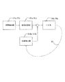
図8は、像振れ補正装置の主要部分の回路構成を示すブロック図である。振動検出部21である振動ジャイロからの(2軸方向の角速度検出のため、21p,21yに区別している)の角速度信号は、信号処理部81p,81yに入力される。信号処理部81p,81yでは角速度信号が積分処理されて角度信号に変換されると共に、DC成分の除去、パンニング対策などが施されて、像振れ補正目標値に変換される。求められた目標値に基づいてコイル58p,58yに電流が与えられ、鏡筒53が像振れ補正のために揺動を始める。位置検出部510p,510yは鏡筒53の揺動を検出してコイル58p,58yに電流を与える負帰還(破線83)構成の公知のフィードバック制御を構築している。このため、鏡筒53は像振れ補正目標値にしたがって正確に駆動される。
FIG. 8 is a block diagram illustrating a circuit configuration of a main part of the image blur correction apparatus. Angular velocity signals from the vibration gyro which is the vibration detector 21 (differentiated to 21p and 21y for detecting the angular velocity in the biaxial direction) are input to the
以上の実施例1においては、撮像素子54を携帯電話の基板22に固定し、それに対してレンズ51,52よりなる撮影光学系を有する鏡筒53を基板22に対して揺動させる像振れ補正装置を構成しているので、振れ補正装置が小型化し、これにより携帯電話の小型化に寄与している。また、レンズ51,52は、被写体光束を撮像素子に結像させるためのレンズの全てであり、共に鏡筒53に組み込まれて一体的なユニットを成すので、組立作業性の向上にも貢献している。
In the first embodiment, the image blur correction is performed by fixing the
図9は本発明の実施例2に係る携帯電話のメインカメラ部付近を示す断面図である。上記実施例1と同様な部分は同一の符号を付し、その説明は省略する。 FIG. 9 is a cross-sectional view showing the vicinity of the main camera portion of the mobile phone according to the second embodiment of the present invention. Portions similar to those in the first embodiment are denoted by the same reference numerals, and description thereof is omitted.
図5と異なるのは、永久磁石58p,58yが基板22に設けられ、コイル59p,59yが鏡筒53に設けられている点である。また、それに伴い、ヨーク57pも基板22に設けられ、磁路を閉じるためにヨーク90pが筐体10aに設けられている点である。
The difference from FIG. 5 is that the
上記のように磁路を閉じた構成にすると、撮影時や携帯電話使用時の磁気ノイズの影響を少なくすることができると共に、コイル59p,59yを貫く磁束密度も高くできる。よって、駆動効率を上げることができる。
When the magnetic path is closed as described above, it is possible to reduce the influence of magnetic noise during photographing or when using a mobile phone, and to increase the magnetic flux density penetrating the
図10は本発明の実施例3に係る携帯電話のメインカメラ部付近を示す断面図である。上記実施例1と同様な部分は同一の符号を付し、その説明は省略する。 FIG. 10 is a sectional view showing the vicinity of the main camera portion of the mobile phone according to the third embodiment of the present invention. Portions similar to those in the first embodiment are denoted by the same reference numerals, and description thereof is omitted.
この実施例3における携帯電話は、鏡筒53と筐体10aとの間に圧縮コイルバネ100が設けられ、位置検出部510p,510yが省かれている。そして、保護窓20aには圧縮コイルバネ100を隠す印刷101が施されている。
In the mobile phone according to the third embodiment, the
上記圧縮コイルバネ100は、鏡筒53を撮像素子54の中心に合わせるようにバネ掛けされている。そして、必要な場合には保護窓20aを外してバネ調整(鏡筒53の光軸50と撮像素子54の中心が合うように最適なバネに交換する)を行えるようになっている。
The
上記実施例1,2では、フィードバック制御していたが、本発明の実施例3では、バネ100と釣り合う推力が発生するようにコイル59p,59yに電流を流す事で、鏡筒53の位置を制御している。そのため、位置検出部510p,510yを省くことができ、簡単な構成で像振れ補正装置を実現できている。
In the first and second embodiments, feedback control is performed. However, in the third embodiment of the present invention, the position of the
図11は本発明の実施例4に係る携帯電話のメインカメラ部付近を示す断面図である。上記実施例1と同様な部分は同一の符号を付し、その説明は省略する。 FIG. 11 is a cross-sectional view showing the vicinity of a main camera portion of a mobile phone according to Embodiment 4 of the present invention. Portions similar to those in the first embodiment are denoted by the same reference numerals, and description thereof is omitted.
上記の実施例1ないし3と異なるのは、鏡筒53内のレンズ51,52が光軸50方向に可動であり、各々ピント調整、ズームを行う点である。
The difference from the first to third embodiments described above is that the
レンズ51は保持枠51aに保持されており、保持枠51aの外径は鏡筒53の内径と嵌合している。よって、光軸50方向には移動可能であるが、それと垂直の方向(矢印132p、132y方向)には鏡筒53に対して移動できない。同様に、レンズ52は保持枠52aに保持されており、保持枠52aの外径は鏡筒53の内径と嵌合している。よって、光軸50方向には移動可能であるが、それと垂直の方向(矢印132p,132y方向)には鏡筒53に対して移動できない。
The
保持枠51aは圧縮コイルバネ51bにより矢印51f方向に付勢されている。その付勢力に対向するように腕51dが設けられている。腕51dは保持枠51aに対して光軸50と垂直の方向(矢印132p,132yの方向)には摺動可能になっている。同様に、保持枠52aは圧縮コイルバネ52bにより矢印51f方向に付勢されている。その付勢力に対向するように腕52dが設けられている。腕52dは保持枠52aに対して光軸50と垂直の方向(矢印132p,132yの方向)には摺動可能になっている。
The holding
腕51dはナット51eを介してねじ軸を有するフォーカスモータ51cに螺結合されている。そのため、フォーカスモータ51cを回転させると、レンズ51aは光軸50方向に移動してピント調節を行う。ピント調節の為のデフォーカスは撮像素子54に結像される像のコントラストの変化、いわゆるTV−AF方式で検出する。腕52dはナット52eを介してねじ軸を有するズームモータ52cに螺結合されている。そのため、ズームモータ52cを回転させると、レンズ52aは光軸50方向に移動して変倍動作を行う。変倍量は撮影者がメインディスプレイ24などで被写体の大きさを確認しながら調節する。
The
鏡筒53の光軸50と垂直な方向(矢印132p,132y)への動作は、上記実施例3と同様に、バネ100と釣り合う推力が発生するようにコイル59p,59yに電流を流す事で鏡筒53の位置を制御している。
The operation of the
上記のように、撮影光学系を構成するレンズ51,52は各々鏡筒53内に保持されているが、それらは鏡筒53外のフォーカスモータ51c、ズームモータ52cにより光軸50方向に駆動されてピント調節やズームを行う構成になっている。よって、各モータの大きさや重さが像振れ補正手段による鏡筒53の駆動負荷にならない構成にできている。
As described above, the
以上、携帯電話における像振れ補正装置を例にして説明を続けてきたが、この像振れ補正装置は小型にまとめることが出来るので、携帯電話に限らず、モバイル機器、携帯端末機器などにも展開できる。 The image blur correction apparatus in the mobile phone has been described above as an example. However, since the image blur correction apparatus can be reduced in size, it can be applied not only to the mobile phone but also to mobile devices and mobile terminal devices. it can.
10a 筐体
20 メインカメラ部
20a 保護窓
21 振動検出部
22 基板
51,52 レンズ
53 鏡筒
54 撮像素子
55 転動ボール
56 圧縮コイルバネ
57p,57y ヨーク
58p,58y 永久磁石
59p,59y コイル
510p,510y 位置検出部
Claims (5)
該撮像手段を保持する基板と、
光軸方向に複数のレンズが配設された撮影光学系を有するレンズ鏡筒と、
前記レンズ鏡筒と前記基板との間に挟まれる3つの転動部材と、
前記基板が取り付けられる筐体のうち前記レンズ鏡筒の光軸方向被写体側の部分と前記レンズ鏡筒との間に取り付けられ、前記レンズ鏡筒を前記基板に対して押し付ける方向へ付勢する付勢部材と、
前記鏡筒を駆動する駆動部材とを有し、
前記駆動部材はコイルとマグネットからなり、前記コイルとマグネットのいずれか一方が前記基板に配置され、当該コイルもしくはマグネットと対向する前記鏡筒の部位に、前記コイルとマグネットのもう一方が配置されることを特徴とする携帯機器。 Imaging means;
A substrate holding the imaging means;
A lens barrel having a photographing optical system in which a plurality of lenses are arranged in the optical axis direction ;
Three rolling members sandwiched between the lens barrel and the substrate;
The lens barrel is attached between the lens barrel and a portion on the subject side of the optical axis direction of the lens barrel in the casing to which the substrate is attached, and is urged to press the lens barrel against the substrate. A force member;
A drive member for driving the lens barrel;
The driving member includes a coil and a magnet, and either the coil or the magnet is disposed on the substrate, and the other of the coil and the magnet is disposed at a part of the barrel facing the coil or the magnet. A portable device characterized by that.
前記振動検出手段の検出結果に基づいて前記鏡筒の駆動量を演算する制御手段を更に有し、
前記駆動手段は、前記制御手段によって演算された駆動量に基づいて前記鏡筒を駆動することを特徴とする請求項1に記載の携帯機器。 Vibration detecting means for detecting the shake of the device;
Further comprising control means for calculating the drive amount of the lens barrel based on the detection result of the vibration detection means;
The portable device according to claim 1, wherein the driving unit drives the lens barrel based on a driving amount calculated by the control unit.
前記位置検出手段は、前記基板の、前記撮像手段が固定される面に設けられ、前記振動検出手段は、前記基板の、前記撮像手段が固定される面とは異なる面に設けられることを特徴とする請求項1または2に記載の携帯機器。 It further has a position detection means for detecting the position of the lens barrel,
The position detecting means is provided on a surface of the substrate on which the imaging means is fixed, and the vibration detecting means is provided on a surface of the substrate different from the surface on which the imaging means is fixed. The portable device according to claim 1 or 2 .
Priority Applications (1)
| Application Number | Priority Date | Filing Date | Title |
|---|---|---|---|
| JP2006245261A JP4963387B2 (en) | 2006-09-11 | 2006-09-11 | Portable device |
Applications Claiming Priority (1)
| Application Number | Priority Date | Filing Date | Title |
|---|---|---|---|
| JP2006245261A JP4963387B2 (en) | 2006-09-11 | 2006-09-11 | Portable device |
Publications (2)
| Publication Number | Publication Date |
|---|---|
| JP2008065221A JP2008065221A (en) | 2008-03-21 |
| JP4963387B2 true JP4963387B2 (en) | 2012-06-27 |
Family
ID=39287969
Family Applications (1)
| Application Number | Title | Priority Date | Filing Date |
|---|---|---|---|
| JP2006245261A Active JP4963387B2 (en) | 2006-09-11 | 2006-09-11 | Portable device |
Country Status (1)
| Country | Link |
|---|---|
| JP (1) | JP4963387B2 (en) |
Families Citing this family (6)
| Publication number | Priority date | Publication date | Assignee | Title |
|---|---|---|---|---|
| JP5348235B2 (en) * | 2009-08-21 | 2013-11-20 | ミツミ電機株式会社 | Lens holder driving device and camera equipped with the same |
| JP5846346B2 (en) | 2009-08-21 | 2016-01-20 | ミツミ電機株式会社 | Camera shake correction device |
| TWI578093B (en) * | 2015-11-02 | 2017-04-11 | 台灣東電化股份有限公司 | Electromagnetic driving module and camera device using the same |
| US11523034B2 (en) | 2016-02-10 | 2022-12-06 | Microsoft Technology Licensing, Llc | Imaging apparatus |
| US10317779B2 (en) | 2016-08-16 | 2019-06-11 | Microsoft Technology Licensing, Llc | Imaging apparatus |
| US11539869B2 (en) | 2020-05-22 | 2022-12-27 | Apple Inc. | Camera with low-profile actuator arrangement |
Family Cites Families (9)
| Publication number | Priority date | Publication date | Assignee | Title |
|---|---|---|---|---|
| JPH086089A (en) * | 1994-06-16 | 1996-01-12 | Nikon Corp | Shake preventing device |
| JP3790829B2 (en) * | 1995-04-21 | 2006-06-28 | 株式会社ニコン | Vibration prevention device using ultrasonic actuator |
| JPH10319465A (en) * | 1997-05-16 | 1998-12-04 | Canon Inc | Lens shifting device |
| JP2003270695A (en) * | 2003-02-13 | 2003-09-25 | Matsushita Electric Ind Co Ltd | Image blurring correction device |
| WO2005036251A1 (en) * | 2003-10-14 | 2005-04-21 | Nidec Copal Corporation | Portable information terminal with camera |
| US7652712B2 (en) * | 2004-10-25 | 2010-01-26 | Mitsubishi Electric Corporation | Lens shifting structure for image capturing apparatus |
| JP4843933B2 (en) * | 2004-11-01 | 2011-12-21 | コニカミノルタオプト株式会社 | Camera shake correction system and photographing apparatus |
| JP4336302B2 (en) * | 2004-12-13 | 2009-09-30 | 三菱電機株式会社 | Imaging device |
| JP4632774B2 (en) * | 2004-12-17 | 2011-02-16 | Necカシオモバイルコミュニケーションズ株式会社 | Imaging device |
-
2006
- 2006-09-11 JP JP2006245261A patent/JP4963387B2/en active Active
Also Published As
| Publication number | Publication date |
|---|---|
| JP2008065221A (en) | 2008-03-21 |
Similar Documents
| Publication | Publication Date | Title |
|---|---|---|
| US20210080808A1 (en) | Anti-shake compensation structure for auto-focus | |
| US7822331B2 (en) | Image blur correction device, lens barrel and imaging apparatus | |
| KR102046472B1 (en) | Mirror Module for OIS and Camera module including the same | |
| JP2008065163A (en) | Shake correction device | |
| JP5079836B2 (en) | Anti-shake structure of lens autofocus module | |
| CN107111208B (en) | Actuator, camera module, and camera mounting device | |
| US7783179B2 (en) | Image blur correction apparatus, lens barrel, and image capture apparatus | |
| JP6152386B2 (en) | Camera drive device | |
| US20180356645A1 (en) | Reflecting module for optical image stabilization and camera module including the same | |
| US8446672B2 (en) | Vibration reduction apparatus with a center of gravity adjusting member to reduce detection errors and optical apparatus | |
| KR20180102946A (en) | Mirror Module for OIS and Camera module including the same | |
| US8369698B2 (en) | Image blur correction apparatus and camera | |
| WO2014076958A1 (en) | Camera drive device | |
| US8184167B2 (en) | Optical apparatus having magnet member | |
| JP4963387B2 (en) | Portable device | |
| JP2012103376A (en) | Camera shaking prevention tilting correction structure for autofocus module | |
| TWI485459B (en) | Imaging device | |
| JP2008191267A (en) | Image blur compensation apparatus, lens barrel and imaging apparatus | |
| JP4878320B2 (en) | Imaging device and portable device | |
| KR102233934B1 (en) | Mirror Module for OIS and Camera module including the same | |
| JP2015215628A (en) | Lens driving device, camera unit, and camera | |
| JP2008129470A (en) | Imaging apparatus and portable electronic equipment | |
| KR102241321B1 (en) | Mirror Module for OIS and Camera module including the same | |
| KR102187734B1 (en) | Mirror Module for OIS and Camera module including the same | |
| JP2007334121A (en) | Vibration correcting device |
Legal Events
| Date | Code | Title | Description |
|---|---|---|---|
| A621 | Written request for application examination |
Free format text: JAPANESE INTERMEDIATE CODE: A621 Effective date: 20090907 |
|
| RD01 | Notification of change of attorney |
Free format text: JAPANESE INTERMEDIATE CODE: A7421 Effective date: 20100520 |
|
| RD01 | Notification of change of attorney |
Free format text: JAPANESE INTERMEDIATE CODE: A7421 Effective date: 20100630 |
|
| A977 | Report on retrieval |
Free format text: JAPANESE INTERMEDIATE CODE: A971007 Effective date: 20110608 |
|
| A131 | Notification of reasons for refusal |
Free format text: JAPANESE INTERMEDIATE CODE: A131 Effective date: 20110614 |
|
| A521 | Request for written amendment filed |
Free format text: JAPANESE INTERMEDIATE CODE: A523 Effective date: 20110804 |
|
| A131 | Notification of reasons for refusal |
Free format text: JAPANESE INTERMEDIATE CODE: A131 Effective date: 20111108 |
|
| A521 | Request for written amendment filed |
Free format text: JAPANESE INTERMEDIATE CODE: A523 Effective date: 20120110 |
|
| TRDD | Decision of grant or rejection written | ||
| A01 | Written decision to grant a patent or to grant a registration (utility model) |
Free format text: JAPANESE INTERMEDIATE CODE: A01 Effective date: 20120321 |
|
| A01 | Written decision to grant a patent or to grant a registration (utility model) |
Free format text: JAPANESE INTERMEDIATE CODE: A01 |
|
| A61 | First payment of annual fees (during grant procedure) |
Free format text: JAPANESE INTERMEDIATE CODE: A61 Effective date: 20120323 |
|
| R151 | Written notification of patent or utility model registration |
Ref document number: 4963387 Country of ref document: JP Free format text: JAPANESE INTERMEDIATE CODE: R151 |
|
| FPAY | Renewal fee payment (event date is renewal date of database) |
Free format text: PAYMENT UNTIL: 20150406 Year of fee payment: 3 |