JP4960929B2 - Brake control device and behavior analysis device for motorcycle - Google Patents
Brake control device and behavior analysis device for motorcycle Download PDFInfo
- Publication number
- JP4960929B2 JP4960929B2 JP2008173908A JP2008173908A JP4960929B2 JP 4960929 B2 JP4960929 B2 JP 4960929B2 JP 2008173908 A JP2008173908 A JP 2008173908A JP 2008173908 A JP2008173908 A JP 2008173908A JP 4960929 B2 JP4960929 B2 JP 4960929B2
- Authority
- JP
- Japan
- Prior art keywords
- vehicle
- lateral
- angle
- inclination
- tilt
- Prior art date
- Legal status (The legal status is an assumption and is not a legal conclusion. Google has not performed a legal analysis and makes no representation as to the accuracy of the status listed.)
- Active
Links
- 238000004458 analytical method Methods 0.000 title claims description 9
- 230000001133 acceleration Effects 0.000 claims description 102
- 230000005484 gravity Effects 0.000 claims description 66
- 238000001514 detection method Methods 0.000 claims description 56
- 230000033001 locomotion Effects 0.000 claims description 33
- 238000012937 correction Methods 0.000 claims description 23
- 238000000034 method Methods 0.000 claims description 22
- 238000004364 calculation method Methods 0.000 claims description 20
- 230000010354 integration Effects 0.000 claims description 6
- 230000007246 mechanism Effects 0.000 claims description 4
- 230000004069 differentiation Effects 0.000 claims description 2
- 238000009795 derivation Methods 0.000 claims 3
- 238000009472 formulation Methods 0.000 claims 1
- 230000008859 change Effects 0.000 description 74
- 230000006399 behavior Effects 0.000 description 62
- 239000013598 vector Substances 0.000 description 34
- 238000009826 distribution Methods 0.000 description 32
- 230000000694 effects Effects 0.000 description 25
- 230000006870 function Effects 0.000 description 18
- 230000006641 stabilisation Effects 0.000 description 16
- 238000011105 stabilization Methods 0.000 description 16
- 238000006243 chemical reaction Methods 0.000 description 12
- 230000007423 decrease Effects 0.000 description 11
- 230000009471 action Effects 0.000 description 9
- 230000000875 corresponding effect Effects 0.000 description 8
- 230000002265 prevention Effects 0.000 description 8
- 230000002441 reversible effect Effects 0.000 description 8
- 230000001276 controlling effect Effects 0.000 description 6
- 230000007935 neutral effect Effects 0.000 description 6
- 230000004044 response Effects 0.000 description 6
- 238000003825 pressing Methods 0.000 description 5
- 238000000691 measurement method Methods 0.000 description 4
- 238000012545 processing Methods 0.000 description 4
- 239000006096 absorbing agent Substances 0.000 description 3
- 230000032683 aging Effects 0.000 description 3
- 239000000446 fuel Substances 0.000 description 3
- 238000012886 linear function Methods 0.000 description 3
- 230000003542 behavioural effect Effects 0.000 description 2
- 230000033228 biological regulation Effects 0.000 description 2
- 230000019771 cognition Effects 0.000 description 2
- 238000013461 design Methods 0.000 description 2
- 238000010586 diagram Methods 0.000 description 2
- 230000005611 electricity Effects 0.000 description 2
- 238000005516 engineering process Methods 0.000 description 2
- 230000003340 mental effect Effects 0.000 description 2
- 230000008447 perception Effects 0.000 description 2
- 230000008569 process Effects 0.000 description 2
- 239000004065 semiconductor Substances 0.000 description 2
- 230000000087 stabilizing effect Effects 0.000 description 2
- 230000002123 temporal effect Effects 0.000 description 2
- 238000012546 transfer Methods 0.000 description 2
- 230000007704 transition Effects 0.000 description 2
- 208000019901 Anxiety disease Diseases 0.000 description 1
- 244000000231 Sesamum indicum Species 0.000 description 1
- 235000003434 Sesamum indicum Nutrition 0.000 description 1
- 230000036506 anxiety Effects 0.000 description 1
- 238000013459 approach Methods 0.000 description 1
- 230000008901 benefit Effects 0.000 description 1
- 230000005540 biological transmission Effects 0.000 description 1
- 239000002131 composite material Substances 0.000 description 1
- 230000006835 compression Effects 0.000 description 1
- 238000007906 compression Methods 0.000 description 1
- 230000008602 contraction Effects 0.000 description 1
- 230000008094 contradictory effect Effects 0.000 description 1
- 238000007796 conventional method Methods 0.000 description 1
- 230000002596 correlated effect Effects 0.000 description 1
- 238000005520 cutting process Methods 0.000 description 1
- 230000006837 decompression Effects 0.000 description 1
- 230000007812 deficiency Effects 0.000 description 1
- 230000001934 delay Effects 0.000 description 1
- 230000003111 delayed effect Effects 0.000 description 1
- 230000000881 depressing effect Effects 0.000 description 1
- 230000006866 deterioration Effects 0.000 description 1
- 238000006073 displacement reaction Methods 0.000 description 1
- 230000007613 environmental effect Effects 0.000 description 1
- 230000004438 eyesight Effects 0.000 description 1
- 238000010191 image analysis Methods 0.000 description 1
- 230000006872 improvement Effects 0.000 description 1
- 238000002347 injection Methods 0.000 description 1
- 239000007924 injection Substances 0.000 description 1
- 238000009434 installation Methods 0.000 description 1
- 238000005259 measurement Methods 0.000 description 1
- 239000002184 metal Substances 0.000 description 1
- 238000012544 monitoring process Methods 0.000 description 1
- 230000002093 peripheral effect Effects 0.000 description 1
- 238000002360 preparation method Methods 0.000 description 1
- 230000010349 pulsation Effects 0.000 description 1
- 230000009467 reduction Effects 0.000 description 1
- 238000011160 research Methods 0.000 description 1
- 230000000630 rising effect Effects 0.000 description 1
- 230000035939 shock Effects 0.000 description 1
- 238000004904 shortening Methods 0.000 description 1
- 238000004088 simulation Methods 0.000 description 1
- 238000012360 testing method Methods 0.000 description 1
- 230000004304 visual acuity Effects 0.000 description 1
- 230000004382 visual function Effects 0.000 description 1
Images


Description
この発明は、自動二輪車 及び 車体が傾斜を伴う三輪車における 車両の挙動検出 方法 及びブレーキ制御装置に関するものである。 The present invention relates to a vehicle behavior detection method and a brake control device in a motorcycle and a tricycle with a vehicle body having a tilt.
従来、走行中の二輪車及び三輪車において 車体が傾斜を伴う走行車両(以降、二輪車として包含して呼ぶ)の安全装置として、転倒の危険性をライダーに警報をする装置(例えば、特開平9−109967号広報等)や車体の傾斜角度に応じて乗員が掛けるブレーキ油圧の圧力上限を変更する装置(例えば、実開平7−11466号広報および特許 第2584587号 等)が存在していた。
しかしながら、ライダーへの警報だけでは、転倒防止の安全策として不十分なのは明らかである。 また、既存のABS装置に対し センサーを付加し傾斜角度の算出を行い 車両の走行速度から ブレーキ油圧のコントロール上限値を単に変更する方法 及び 車輪のスリップ率の算出を行い傾斜状態あわせ目標スリップ率を可変する方法では、 加減速に伴う荷重配分の変動、ライダー体重の変化による車両荷重の変化、傾斜走行状態における車両挙動が安定なのか不安定なのかを判断できる客観的基準が無いために、ライダーの意思を尊重することができないばかりか、ライダーによるブレーキの操作がないと機能しないため走行中に起きた車両挙動変化に応じて 自動的に車両を安定状態へ遷移することができなかった。
4輪車に比べ大きな荷重変化を伴う二輪車は 目まぐるしく変化する車両走行状態に対し 傾斜角度だけで追従する事は困難である。
2. Description of the Related Art Conventionally, as a safety device for a traveling vehicle (hereinafter referred to as a two-wheeled vehicle) in which a vehicle body is inclined in a traveling two-wheeled vehicle and a three-wheeled vehicle, a device that warns a rider of a risk of falling (for example, Japanese Patent Laid-Open No. 9-109967) Etc.) and devices for changing the upper pressure limit of the brake hydraulic pressure applied by the occupant in accordance with the inclination angle of the vehicle body (for example, Japanese Utility Model Publication No. 7-11466 and Japanese Patent No. 2584587).
However, it is clear that a warning to the rider alone is not sufficient as a safety measure for preventing a fall. In addition, a sensor is added to the existing ABS device to calculate the tilt angle, the method of simply changing the brake hydraulic pressure control upper limit value from the running speed of the vehicle, the calculation of the wheel slip ratio, and the target slip ratio according to the tilt state. In the variable method, there is no objective standard that can determine whether the load distribution changes due to acceleration / deceleration, the vehicle load changes due to a change in the rider's weight, and whether the vehicle behavior is stable or unstable when the vehicle is traveling in an incline. In addition to not being able to respect the will of the vehicle, it would not function without the rider's braking operation, and therefore the vehicle could not be automatically transitioned to a stable state in response to changes in vehicle behavior that occurred during driving.
A two-wheeled vehicle with a large load change compared to a four-wheeled vehicle is difficult to follow a rapidly changing vehicle running state only by an inclination angle.
実際の走行では、左右スラロームや高速でコーナーを通過するような状況の場合 後輪だけでなく、前輪までも横すべりを起こしている場合もあり 傾斜角を検出するための横Gセンサーだけでは 実走行状態と停止時の傾斜角とは一致せず 車両挙動を正確に把握することは困難である。 In actual driving, when the vehicle passes through a corner at left and right slaloms or at high speed, it may have caused a side slip not only to the rear wheel but also to the front wheel. Actual driving only with the lateral G sensor to detect the inclination angle The state and the inclination angle at the time of stopping do not match, so it is difficult to accurately grasp the vehicle behavior.
二輪車の走行時の技量は千差万別であり、転倒防止能力も運転技量に依存するものであり、運転経験の少ないライダーほど転倒の危険性に対する察知が遅れやすく、転倒を回避するための操作も 遅れたり 操作が粗くなったりして、転倒の危険性を助長させる要因になる。 ベテランライダーであっても 突然の飛び出しに対しては ブレーキと操舵操作・重心のバランスをとり 転倒回避することは難しいことであり 潜在的な問題点が存在している。
また、日本は高齢化社会の傾向であると云われており 高齢化に伴い環境への反応が悪くなっていき、適切な操作能力が低下していくことが知られている。 それは 運転経験の少ないライダー同様に遅い反応・荒い操作 が車両を不安定にする場合も少なくない。
一方、いくら運転経験を増しても傾斜限界は分り難く、傾斜限界付近を認識する為に傾斜角度をカーブ途中でさぐる様な傾斜操作を行うものであり、路面μが高い状態であれば 車体の一部(ステップにある金属製のバンクセンサー等)を路面に接地させることで車両の傾斜限界を認識したりする。
二輪車は車両構造上、倒れるという特徴を持っている。 一般的には、高速になるに従い安定し、低速になるに従い不安定となり、足を着かなければ通常倒立して停止することができない。 しかしながら、安定と言われる中高速走行時でさえも無理な操作・路面の急激な変化による車両挙動の変化に対して、二輪車は不安定となり最悪の場合転倒に至る可能性が存在している。
このような乗り物に対し、走行時の車両の挙動に対して 不安を少しでも低減することが出来るならばライダーは、安全に運転技量を身につけることができると同時に 操作に対して過度に慎重になることが不要になるため 過度な緊張から開放され周囲の状況にも配慮ができる余裕が生まれるため 安全に対する意識マージンが大幅に向上し 疲労も低減できる筈である。
二輪車は、その特徴である傾斜をコントロールして その先のカーブに合わせ車体を左右にロール(傾斜)させ 行きたい方向に曲がっていく。 時には、速度がカーブに対して過剰であったと感じられれば ブレーキによる制動などを加え スピード抑制しカーブを通過する。
The riding skills of motorcycles vary greatly, and the ability to prevent toppling depends on the driving skills. Riders with less driving experience are more likely to be late to detect the danger of falling, and operations to avoid falling However, delays and rough operations can increase the risk of falling. Even for an experienced rider, it is difficult to balance the brake and steering operation and the center of gravity against sudden jumps, and there is a potential problem.
In addition, it is said that Japan is a trend toward an aging society, and it is known that with the aging of society, the response to the environment worsens and the appropriate operation ability declines. As with riders with little driving experience, slow response and rough operation can often destabilize the vehicle.
On the other hand, no matter how much driving experience is increased, the tilt limit is difficult to understand, and in order to recognize the vicinity of the tilt limit, the tilt operation is performed such that the tilt angle is searched in the middle of the curve. A part of the vehicle (such as a metal bank sensor in the step) is grounded to the road surface to recognize the tilt limit of the vehicle.
The two-wheeled vehicle has a feature that it falls down due to the vehicle structure. In general, it becomes stable as the speed increases, and becomes unstable as the speed decreases. However, there is a possibility that the two-wheeled vehicle becomes unstable and falls down in the worst case against the change of the vehicle behavior due to the unreasonable operation and the rapid change of the road surface even during the medium-high speed driving which is said to be stable.
For such vehicles, if the anxiety about the behavior of the vehicle during driving can be reduced as much as possible, the rider can acquire the driving skill safely and at the same time be overly careful about the operation. Since it becomes unnecessary, there is a room to be released from excessive tension and to be able to consider the surrounding situation, so the safety awareness margin can be greatly improved and fatigue can be reduced.
Two-wheeled vehicles control their characteristic tilt, roll the vehicle to the left and right (tilt) according to the curve ahead, and turn in the direction you want to go. Sometimes, if it feels that the speed is excessive with respect to the curve, the brake is applied and the speed is controlled to pass the curve.
このことは、カーブ(旋回半径r)に合わせ 速度コントロールと傾斜コントロールの両方をライダーは感じとって 状態をフィードバックしてコントロールしている。 This means that the rider feels both speed control and tilt control according to the curve (turning radius r), and controls the situation by feeding back the state.
このプロセスは、教習所の過程でもあるように、 知覚→認知→判断→操作 の一連の動作を繰り返すことで学び 運転を可能としている。 This process enables learning and driving by repeating a sequence of perception → cognition → judgment → operation, which is also a process of a school.
実際のカーブを曲がる状況は、回転半径一定の一つのカーブあっても ライダーがイメージした走行ラインは無数に描けるものであり 加減速を伴うことでも旋回半径は時々刻々と変化するものであるため ライダーは複雑な状態をコントロールしていることになる。 The situation of turning an actual curve is that even if there is one curve with a constant turning radius, the rider's image of the running line can be drawn innumerably, and even with acceleration / deceleration, the turning radius changes from moment to moment. Is controlling a complex state.
この複雑なコントロールをする人間の能力は、年齢を増す毎に低下傾向にあることが知られており 運転に必要な情報の90%以上は視覚に依存し、視覚機能の低下は 移動対象の知覚・認知に関係の深い動体視力や 距離判断を伴う空間認識に影響することが関係分野の研究が報告されている。
よって、高齢化社会を迎える背景にある日本では 機能低下を補う安全装置の必然性が潜在的に存在することが見てとれる。
今日では、ABSと呼ばれるシステムや コンバインドブレーキと呼ばれる前後連動ブレーキシステム が合体されたブレーキ装置 の登場により、直進走行時のブレーキによる車輪のロックを防ぐ制御システムにより直進のブレーキ安定性はかなり向上してきた。
しかしながら、走行中の傾斜角変化に応じてブレーキ油圧を加圧減圧し制御による自動減速を行いながら 車両挙動を安定化に導くための装置は存在していなかった。
また、今後時代の変化に伴って 現在は油圧によるブレーキ制動が大半であるが 今後環境への配慮など さまざまな条件により 油圧から電機モーターによるブレーキ制御が主流をしめる可能性もあり、その対応を明記しておく。
Therefore, it can be seen that there is a potential necessity for safety devices to compensate for the decline in function in Japan, which is facing the aging society.
Nowadays, with the advent of a brake system that combines a system called ABS and a front-rear interlocking brake system called a combined brake, the stability of straight-braking brakes has been significantly improved by a control system that prevents the wheels from being locked by the brake when running straight ahead. .
However, there has been no device for stabilizing the vehicle behavior while automatically decelerating the brake hydraulic pressure in response to changes in the tilt angle during traveling.
In addition, with the change of the future, brake braking by hydraulic pressure is now the majority, but there are possibilities that brake control by electric motor from hydraulic pressure will become mainstream due to various conditions such as environmental considerations in the future. Keep it.
従来、二輪車に対して様々な安全のための警報装置やライダーの掛けるブレーキを補助するABSなど提案されているが、背景技術で述べたように どれもライダーのブレーキ操作による車輪のロックを防止する 油圧コントロール装置に過ぎなかった。 Conventionally, various safety warning devices for motorcycles and ABS for assisting rider's brakes have been proposed, but as described in the background art, all prevent the rider's brake operation from locking the wheel. It was just a hydraulic control device.
安全装置を論じる際、これまで傾斜角を検出する方式が数多く提案されてきたが 実際の車両挙動検出において、傾斜角度を横Gセンサーから算出した検知方法では 車両が停止している状況において 傾斜角は正確に計測できても、一度走り出してしまえば 車両に掛かる遠心力の作用により 検出されたGセンサーの値からでは 傾斜角度を算出することができなかった。 (特開2004−93537 の問題点)
また、同様に車両挙動検出において、角速度センサーのみにより 横方向の傾斜角が算出される積分方法では、倒立を示す絶対角度の情報(積分の初期値)がないため システムの電源が投入された状態が倒立状態として 誤認識をしてしまう可能性が対応できなかった。 (特開2004−155412 問題点)
本考案は、これまで関連づけされてこなかった 走行時の横Gセンサーと角速度センサーを関連づけし これまで正確な傾斜角の検出ができなかった諸問題を解決し 車両の走行状態での正確な横Gを検出することを可能するものである。
同時に、横Gセンサーと角速度センサーの明確な関連により 車両の挙動を把握することが可能になったことで これまで実現困難であった車両を安定化に導く自動ブレーキシステムの提案により 転倒抑制を行うことを可能とした車両挙動安定化の為の自動ブレーキ装置の実現を課題とする。
ライダーのスキルによって 走り方の限界は変化する。 傾斜角がその一つであり、現状では傾斜角が限界に近づいても車体の一部が接しなければライダーは分る術が存在していない。
天候や気温もその要因であり、雨で路面が濡れている状況下で 晴天のような勢いでコーナーを傾斜させていくと傾斜限界角度になるずっと前の傾斜の浅い状態からタイヤが滑り出し 転倒にいたる可能性も危惧される。
よって、ライダーのスキルに対応したシステムが要望される。
In discussing safety devices, a number of methods for detecting the tilt angle have been proposed so far, but in actual vehicle behavior detection, the detection method in which the tilt angle is calculated from the lateral G sensor is used when the vehicle is stopped. Although it was possible to measure accurately, the slope angle could not be calculated from the G sensor value detected by the action of the centrifugal force applied to the vehicle once it started running. (Problems of JP-A-2004-93537)
Similarly, in vehicle behavior detection, in the integration method in which the lateral inclination angle is calculated only by the angular velocity sensor, there is no information on the absolute angle that indicates inversion (the initial value of integration), so the system is powered on. Could not cope with the possibility of misrecognizing as an inverted state. (Problems of JP-A-2004-155212)
The present invention relates a lateral G sensor and angular velocity sensor that has not been linked so far to solve various problems that have not been able to detect an accurate inclination angle until now. Can be detected.
At the same time, it is possible to grasp the behavior of the vehicle due to the clear relationship between the lateral G sensor and the angular velocity sensor, and to prevent overturning by proposing an automatic brake system that leads to stabilization of the vehicle that has been difficult to realize so far An object of the present invention is to realize an automatic brake device for stabilizing the behavior of a vehicle.
Depending on the skill of the rider, the limit of how to run changes. The tilt angle is one of them, and at present, even if the tilt angle approaches the limit, there is no way for the rider to know if a part of the vehicle body does not touch.
The weather and temperature are also factors, and when the road surface is wet due to rain, if the corner is tilted with a momentum like a clear sky, the tire will begin to slip from the shallow state of the slope long before the tilt limit angle is reached. There is also concern about the possibility.
Therefore, a system corresponding to the rider's skill is desired.
本発明は、前記課題を解決するために 二輪車の傾斜時に発生する理論横G(規範Gと呼
べる)を導く理論式を明確化し 車両挙動の判断するための基準を提供する。
及び 二輪車の挙動検出の為に 少なくとも傾斜加速度センサーと傾斜から生じる横方向
加速度を検出するための加速度センサーを搭載し、そのセンサーから検出される信号に基
づき 走行中に発生する傾斜角度・傾斜角速度・傾斜角加速度の各値が 予め設定される
閾値以下になるように ライダーの操作によらず前後輪のブレーキ圧力を 加圧減圧の全
てをコントロールするための手段を提供する。
具体的には、新請求項1として記載の
あ) ECUからの制動指令により車両を減速させるためには、車輪への制動をエンジンブレーキ力やブレーキディスクへのブレーキ力の調整を行うことで実施される。
自動車では各輪へのブレーキ制御として、4輪ESC(横滑り防止装置)と呼ばれる装置でも油圧ブレーキ制御と併用し、エンジン制御がおこなわれており、多く先願が示す様に技術としては公知である。
い) しかしながら、本出願に示される様にブレーキ力が車体を倒立側にしたり傾斜側にしたりする関係を明記し、傾斜の制御に言及するものは存在しなかった。
エンジンブレーキもブレーキ手段の一つであり、ほとんどのライダーはカーブ直前の傾斜時にアクセルを戻す操作をし、エンジンブレーキを効果的に用いてスムーズな重心移動と車体挙動をつくりだしカーブを通過していくことが「0112」に記述される。
う) 本出願も燃料制限を効果的に加えることで、アクセルを戻す操作と同様の効果を意図的に得られ、マイルドな車体の傾斜変化を実現していくことが「0113」にも記述される。
新請求項2に記載の内容は、
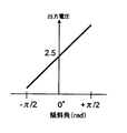
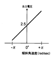
え) 角速度だけでも制御可能であるが、よりスムーズでマイルドな車体の傾斜変化を実現するためには、傾斜の角速度以外にも運動エネルギー算出をするために角加速度が必要であり、更に、傾斜角に応じた挙動のセッティングができるように傾斜角度も必要になることが図17に記述される。
新請求項3に記載の内容は、
お) 加速度センサーを車両に付加しただけでは「0003」記述の問題は解決できない。角速度補正することで、傾斜角度が変化しても姿勢の判断が可能となる。 また、傾斜角に応じた理論検出横Gの実車合わせ込み手法が記述されている。
新請求項4に記載の内容は、
か) 傾斜時の路面接地点の変化が分れば、理論的に加速度センサーで検出される理論検出横Gを算出することが可能であることが、記述されている。
横Gの発生メカニズムの根幹を示したものであり、ライダーが実際に傾斜コントロールをする上で基準が存在することが判明したため、理論検出横Gを規範横Gと称して説明している。
新請求項5に記載の内容は、
き) 車両の挙動解析が可能となり、挙動抑制のためのブレーキ装置が可能となる。挙動解析により、今までのシミュレーション解析をより向上させることが可能となる。偏差横Gは、走行時の安定度を示す。
周辺技術情報としては、
く) 四輪車は、‘78年ABS装着車‘95年ESP(横滑り防止装置)装着車が量産車として上市される。 ガソリンとMOTORの両駆動源を持つハイブリッドカーについては、‘97年10月量産車初上市。‘07年電気自動車が、東京MOTORショーで発表、‘09年初登録される。
け) 一方、二輪車は、‘88年ABSの上市、‘96年前後輪連動ABSブレーキの上市。電動バイクについては、‘02年11月より地域限定ながら発売されている。 自転車とエンジンのハイブリッドが、‘66年には存在していた。
In order to solve the above-mentioned problems, the present invention clarifies a theoretical formula that leads to a theoretical lateral G (which can be referred to as a reference G) that occurs when a motorcycle is tilted, and provides a reference for judging vehicle behavior.
And at least a tilt acceleration sensor and an acceleration sensor for detecting the lateral acceleration resulting from the tilt for detecting the behavior of the two-wheeled vehicle. A means is provided for controlling all of the pressurization and depressurization of the front and rear wheels regardless of the rider's operation so that each value of the inclination angular acceleration is not more than a preset threshold value.
Specifically, as described in the
A) In order to decelerate the vehicle by the braking command from the ECU, the braking to the wheel is performed by adjusting the engine braking force and the braking force to the brake disc.
In automobiles, as a brake control for each wheel, a device called a four-wheel ESC (side skid prevention device) is also used in combination with a hydraulic brake control, and engine control is performed. .
However, as shown in the present application, there is nothing that clearly describes the relationship between the braking force turning the vehicle body upside down or tilting the vehicle, and mentions tilt control.
Engine brakes are also a means of braking, and most riders operate to return the accelerator when leaning just before the curve, and use the engine brake effectively to create a smooth center of gravity movement and vehicle behavior and pass through the curve. Is described in “0112”.
It is also described in “0113” that this application also intentionally obtains the same effect as the operation of returning the accelerator by effectively applying fuel restriction, and realizing a mild change in the inclination of the vehicle body. The
The content of the
D) Although it can be controlled only by angular velocity, in order to realize a smoother and milder vehicle body inclination change, in addition to the angular velocity of inclination, angular acceleration is required to calculate kinetic energy. It is described in FIG. 17 that an inclination angle is necessary so that the behavior can be set according to the angle.
The content of the
O) The problem described in “0003” cannot be solved simply by adding an acceleration sensor to the vehicle. By correcting the angular velocity, it is possible to determine the posture even if the inclination angle changes. In addition, a method of fitting the actual vehicle of the theoretical detection lateral G according to the inclination angle is described.
The content of the
It is described that the theoretical detection lateral G that can be theoretically detected by the acceleration sensor can be calculated if the change of the road contact point at the time of inclination is known.
This shows the basis of the lateral G generation mechanism, and since it has been found that there is a reference for the rider to actually control the inclination, the theoretical detection lateral G is referred to as a reference lateral G.
The content of the
B) It becomes possible to analyze the behavior of the vehicle and to enable a brake device to suppress the behavior. The behavioral analysis can improve the simulation analysis so far. The deviation horizontal G indicates the stability during traveling.
As peripheral technical information,
C) As for automobiles, '78 ABS equipped vehicles''95 ESP (side slip prevention device) equipped vehicles will be marketed as mass-produced vehicles. The first hybrid car with both gasoline and MOTOR drive sources was launched in October 1997. '07 electric car was announced at the Tokyo MOTOR show and registered in 2009 for the first time.
K) On the other hand, motorcycles were put on the market in 1996 with ABS, and in 1996 with the front and rear wheel-linked ABS brakes. Electric motorcycles have been on sale since November 2002, limited to the region. Bicycle and engine hybrids existed in 1966.
これまで関連付けされてこなかった走行時の傾斜角と横Gの関係が明確になり、走行状態での車両挙動が評価できるようになった。 これにより、傾斜走行時に傾斜角に応じ車両を安定に制御するための基準(規範横G)が存在し計算できることが明確になった。
その結果、これまで不可能であった経験豊かなライダーの乗り方をデータとして共通解析できると供に、制御ユニットへ運転ノウハウを落とし込めることが可能であり、車両傾斜時のブレーキアシストによる車両の安定制御が可能となり ライダーの転倒抑制を行うことができる様になった。
強いては、ライダーの操作遅れによる過度な粗い操作と不安定な挙動 及び傾斜中の難しいブレーキ操作 から精神的負担が減り、次の操作へ精神的な余裕や 操作マージンが生まれるため 周囲への交通事情に配慮が可能なため 安全度が増すことを可能とした。
The relationship between the inclination angle and the lateral G during traveling, which has not been associated so far, has been clarified, and the vehicle behavior in the traveling state can be evaluated. As a result, it has become clear that there is a standard (standard lateral G) for stably controlling the vehicle in accordance with the inclination angle when the vehicle is inclining and can be calculated.
As a result, it is possible to share the experience of riders with experienced riders, which was impossible until now, as data, and to apply driving know-how to the control unit. Stable control is now possible, and the rider can be prevented from falling.
For the most part, the mental burden is reduced from excessive rough operation and unstable behavior due to the delay of the rider's operation, and difficult braking operation while inclining, creating a mental margin and operating margin for the next operation. It is possible to increase the safety level because it can be considered.
この考案は、前記課題を解決するためのであり、これまで不可能であった経験豊かなライダーから得たノウハウである 速度と傾斜角度・傾斜速度・傾斜角加速度(「速度とロールの関係」と以降呼ぶ)などの情報を解析することを可能とし 初心ライダーでもスキルライダーの運転ノウハウである 運転技術の恩恵を得られるように これまでのアンチロックブレーキでの操作領域にとどまらず 車体傾斜時のコントロールまで領域を拡大し 走行中に発生し得る不安定な挙動をライダーのブレーキ操作如何を問わず ブレーキ制御を行うことにより 安定な挙動へ遷移するためにライダーに成り代りブレーキの操作補助を行うことを目的とした 車両安定化ブレーキ制御装置を提供するものである。 This device is intended to solve the above-mentioned problems, and is the know-how obtained from experienced riders, which was impossible before. Speed, tilt angle, tilt speed, tilt angle acceleration ("Relationship between speed and roll") So that even beginner riders can benefit from the driving skills that are the driving know-how of skill riders. In order to make the transition to stable behavior by performing brake control regardless of the rider's brake operation, it is necessary to assist the rider on behalf of the rider. The purpose of the present invention is to provide a vehicle stabilization brake control device.
図1は 車両安定化ブレーキ制御装置のシステム搭載車の構成が示される。
図1の説明に入る。 二輪車の車体10 には、車両の挙動を検出するハイブリッドセンサー20 が搭載される。 ハイブリッドセンサー20 には、車両進行方向の加速度が測定できる加速度センサー21、進行方向の左右傾斜角速度(ロール方向の傾斜速度)を測定できる角速度センサー22(ヨーレートセンサー又はジャイロセンサーと呼ばれることがある)、及び進行方向に90度向きの異なる左右の横加速度を測定できる加速度センサー23 が内蔵される。
2つの車輪には、ホイールの回転速度を検出する前輪車輪速センサー24 及び後輪車輪側センサー25、 前輪のダンパーの距離を測定するストロークセンサー26、 後輪のダンパー距離を測定するストロークセンサー27 及び 前輪後輪へのブレーキ油圧を独立して加圧減圧できるブレーキ油圧コントロールユニット30 から構成される。
ここで使用されるハイブリッドセンサー20 は、二方向の加速度を検出する加速度センサーと角速度センサーが一体化したものであり、多くの4輪車において普及を見せてきている横滑り防止装置(ESCと呼ばれるが、自動車会社によりシステム名称が異なっている)と呼ばれるシステムに使用される 半導体センサー技術を用いている。 ひとつの小型パッケージで、それら全てのセンサーが内蔵されているため、二輪車への搭載を可能にしている。 本ハイブリッドセンサー20 は、車体の重心位置近くにレイアウトさることにより 検出精度とコントロール精度を高く維持することができる。
FIG. 1 shows the configuration of a vehicle equipped with a vehicle stabilization brake control system.
The description of FIG. A
The two wheels include a front wheel speed sensor 24 and a rear
The
ブレーキ油圧コントロールユニット30 は、4輪車で既に実証されている横滑り防止装置の油圧系を基に 油圧系の規模を4チャンネルから2チャンネルに半減したもので 二輪車へのブレーキ油圧への適用を図ったものであり 図2で示す。
図2は、車両安定化ブレーキ制御装置の油圧構成であり、ECUと呼ばれるコンピューターを搭載したコントロールユニットにより 油圧コントロールがされる。
通常、制動のための油圧コントロールはライダーにより前輪はレバー入力 後輪はぺダル入力によりブレーキ力が加えられる。
前輪であれば、マスターシリンダー(MC−F)により油圧に変換され、発生した油圧は SV1(ソレノイドバルブ1)を通過し SV2を通過して BC1・BC2のブレーキシリンダーへ圧力が加えられ、ブレーキがかかる。 ブレーキが放されれば、BC1・BC2にくわえられた圧力は 圧力が加えられた順路をさかのぼり 経路たどってMC−Fを押し戻す。 ECUによるコントロールのないコンベンショナルな動きとしては、SV1・SV2の電磁ソレノイドは通常開いており、ECUからの通電によりソレノイドは閉じ油圧の往来ができなくなる。 SV3・SV4については、通常閉じておりECUからの通電によりソレノイドは開き油圧の往来が可能となる。
いま、走行中に前輪へのブレーキが必要な状況と判断されると 加圧ポンプに通電がされ電磁モーターポンプP により発生した油圧は逆流防止弁3aを通じてSV2を経由してBC1・BC2にブレーキ圧力が加圧される。 途中SV1を通電しておくことで レバー側へ圧力が逃げることを防止できる。 BC1・BC2に加圧された油圧力は、SV2に通電することでSV2は閉じ 一定の圧力を維持することができる。 走行状態に変化が生じ、ブレーキが不要となれば、加圧されたブレーキ油圧をSV3に通電することでSV3を開き 圧力のかかった油はリザーバーFへ戻され BC1・BC2の圧力は減圧する。 この一連の動作のなかで、ライダーによる意図的なブレーキがかけられた場合 MC−Fにより発生した油圧は 圧力を下げないとブレーキの固着と間違えられる可能性がありライダーをビックリさせる原因となりかねない。
The brake
FIG. 2 is a hydraulic configuration of the vehicle stabilization brake control device, and hydraulic control is performed by a control unit equipped with a computer called an ECU.
Usually, the hydraulic control for braking is applied by the rider by the rider and the rear wheel by lever input, and the rear wheel by pedal input.
If it is a front wheel, it is converted to hydraulic pressure by the master cylinder (MC-F), and the generated hydraulic pressure passes through SV1 (solenoid valve 1), passes through SV2, and pressure is applied to the BC1 and BC2 brake cylinders, causing the brake to Take it. When the brake is released, the pressure added to BC1 and BC2 goes back along the route in which the pressure was applied and pushes back MC-F. As a conventional movement without control by the ECU, the SV1 and SV2 electromagnetic solenoids are normally open, and the solenoids are closed by energization from the ECU, so that the hydraulic pressure cannot be transferred. SV3 and SV4 are normally closed, and the solenoid is opened by energization from the ECU, and the hydraulic pressure can be transferred.
If it is judged that the front wheels need to be braked while driving, the hydraulic pressure generated by the electromagnetic motor pump P through the pressure pump is applied to the BC1 and BC2 via the backflow prevention valve 3a via the SV2. Is pressurized. It is possible to prevent the pressure from escaping to the lever side by energizing SV1 halfway. The hydraulic pressure applied to BC1 and BC2 can be maintained at a constant pressure by closing SV2 by energizing SV2. If a change occurs in the running state and the brake becomes unnecessary, the SV3 is opened by energizing the pressurized brake hydraulic pressure to the SV3, the pressurized oil is returned to the reservoir F, and the pressures of BC1 and BC2 are reduced. In this series of actions, when the brakes are intentionally applied by the rider, the hydraulic pressure generated by the MC-F may be mistaken for the brake to be fixed unless the pressure is lowered, which may cause the rider to be surprised. .
したがって、油圧センサーの圧力を検出することが可能なプレッシャーセンサー(P/S−F)の圧力をみてライダーの意思を確認することが可能で SV4への通電によりバルブを開き MC−Fにより発生した圧力を減圧させることで システムの動作をライダーに伝えることを可能としている。 上記の様なブレーキシリンダーへの油圧の加圧減圧をモーター通電・バルブへの通電を適切に繰り返すことにより、一連の油圧コントロールを目標油圧に調整できる様に動作を繰り返す制御がなされる。 逆流防止弁は、3aのほかに 1a・2aも同一のものを使用し 油圧の流れを電気によらず制限している。 Therefore, it is possible to confirm the rider's intention by looking at the pressure of the pressure sensor (P / S-F) that can detect the pressure of the hydraulic sensor. The valve is opened by energizing the SV4 and generated by the MC-F. By reducing the pressure, it is possible to convey the operation of the system to the rider. By appropriately repeating the pressurization and depressurization of the hydraulic pressure to the brake cylinder as described above and the energization of the motor and the valve, the control is repeated so that a series of hydraulic controls can be adjusted to the target hydraulic pressure. In addition to 3a, the same 1a and 2a are used for the backflow prevention valve, and the hydraulic flow is restricted regardless of electricity.
後輪についても同様であるが、ペダル入力によって発生する油圧如何を問わず モーターPの通電により油圧の発生をさせることができ ブレーキシリンダーへ圧力コントロールされた油圧を加圧減圧の調整をすることでブレーキ力のコントロールをECUにより制御される。
詳細を説明すれば、
後輪は、マスターシリンダー(MC−R)により油圧に変換され、発生した油圧は SV5(ソレノイドバルブ5)を通過し SV6を通過して BC3のブレーキシリンダーへ圧力が加えられ、ブレーキがかかる。 ブレーキが放されれば、BC3にくわえられた圧力は 圧力が加えられた順路をさかのぼり 経路たどってMC−Rを押し戻す。 ECUによるコントロールのないコンベンショナルな動きとしては、SV5・SV6の電磁ソレノイドは通常開いており、ECUからの通電によりソレノイドは閉じ油圧の往来ができなくなる。
The same applies to the rear wheels. Regardless of the hydraulic pressure generated by pedal input, the hydraulic pressure can be generated by energizing the motor P, and the pressure controlled by the brake cylinder can be adjusted by adjusting the pressure. The brake force is controlled by the ECU.
In detail,
The rear wheels are converted to hydraulic pressure by the master cylinder (MC-R), and the generated hydraulic pressure passes through SV5 (solenoid valve 5), passes through SV6, and pressure is applied to the brake cylinder of BC3, and braking is applied. When the brake is released, the pressure applied to BC3 goes back the route in which the pressure was applied and pushes back MC-R. As a conventional movement without control by the ECU, the SV5 and SV6 electromagnetic solenoids are normally open, and the solenoids are closed by energization from the ECU, and the hydraulic pressure cannot be transferred.
SV7・SV8については、通常閉じておりECUからの通電によりソレノイドは開き油圧の往来が可能となる。
いま、走行中に前輪へのブレーキが必要な状況と判断されると 加圧ポンプに通電がされ電磁モーターポンプP により発生した油圧は逆流防止弁6bを通じてSV6を経由してBC3にブレーキ圧力が加圧される。 途中SV5を通電しておくことで レバー側へ圧力が逃げることを防止できる。 BC3に加圧された油圧力は、SV6に通電することでSV6は閉じ 一定の圧力を維持することができる。 走行状態に変化が生じ、ブレーキが不要となれば、加圧されたブレーキ油圧をSV7に通電することでSV7を開き 圧力のかかった油はリザーバーへ戻され BC3の圧力は減圧する。 この一連の動作のなかで、ライダーによる意図的なブレーキがかけられた場合 MC−Rにより発生した油圧は 圧力を下げないとブレーキの固着と間違えられる可能性がありライダーをビックリさせる原因となりかねない。
SV7 and SV8 are normally closed, and the solenoid is opened by energization from the ECU, and the hydraulic pressure can be transferred.
If it is determined that the front wheels need to be braked while traveling, the hydraulic pressure generated by the electromagnetic motor pump P through the
したがって、油圧センサーの圧力を検出することが可能なプレッシャーセンサー(P/S−R)の圧力をみてライダーの意思を確認することが可能で SV8への通電によりバルブを開き MC−Rにより発生した圧力を減圧させることで システムの動作をライダーに伝えることを可能とするものである。 上記の様なブレーキシリンダーへの油圧の加圧減圧をモーター通電・バルブへの通電を適切に繰り返すことにより、一連の油圧コントロールを目標油圧に調整できる様に動作を繰り返す。 逆流防止弁は、6bのほかに 4b・5bも同一のものを使用し 油圧の流れを電気によらず制限している。 Therefore, it is possible to confirm the rider's intention by looking at the pressure of the pressure sensor (P / S-R) that can detect the pressure of the hydraulic sensor. By reducing the pressure, it is possible to convey the operation of the system to the rider. By repeating the pressurization and depressurization of the hydraulic pressure to the brake cylinder as described above, the operation is repeated so that the series of hydraulic controls can be adjusted to the target hydraulic pressure by appropriately repeating the energization of the motor and the energization of the valve. In addition to 6b, the same 4b and 5b are used for the backflow prevention valve, and the hydraulic flow is restricted regardless of electricity.
システムの電気的な構成を図3で表す。 図3は、車両安定化ブレーキ装置のECU内部ブロック構成を表したものである。
図の左側には入力信号が示されており 車両の挙動を検出する図1で示される各センサーと 図2で示される前輪後輪ブレーキの油圧系圧力を検出する圧力センサーP/S−F 及び P/S−R が入力されている。
各センサーからの信号を演算処理マイコンの各ブロックで適切な演算を行い 結果として図の右側に示されるアクチュエターへの出力として 加圧ポンプモーターPへの通電 及び SV1〜SV8のソレノイドバルブへの通電 を行う。
図2の油圧系の構成と図3のECU構成は 紙面の都合上 別々に記述されるが、近年の技術進化により、油圧バルブ・油圧ポンプなどの油圧系の小型化や 制御マイコンの処理能力の向上 通電コントロールを行う半導体の進化により 油圧コントロールユニットと電子制御ユニットの一体化が可能になってきている。
また、ブレーキ構成についても前後独立型で説明しているが 連動ブレーキによるコンバインド型との組合せに対しても応用が可能なものである。
The electrical configuration of the system is shown in FIG. FIG. 3 shows an ECU internal block configuration of the vehicle stabilization brake device.
An input signal is shown on the left side of the figure. Each sensor shown in FIG. 1 that detects the behavior of the vehicle, and a pressure sensor P / S-F that detects the hydraulic system pressure of the front and rear wheel brakes shown in FIG. P / S-R is input.
Appropriate calculation is performed in each block of the processing microcomputer for the signals from each sensor. As a result, the output to the actuator shown on the right side of the figure is energized to the pressurization pump motor P and the solenoid valves SV1 to SV8 are energized. I do.
The configuration of the hydraulic system in FIG. 2 and the ECU configuration in FIG. 3 are described separately for the sake of space. However, due to recent technological evolution, the hydraulic system such as hydraulic valves and hydraulic pumps can be downsized and the processing capacity of the control microcomputer can be reduced. Improvement The evolution of semiconductors that control energization has made it possible to integrate hydraulic control units and electronic control units.
The brake configuration is also described as a front-rear independent type, but it can also be applied to combinations with a combined type with interlocking brakes.
図2は、油圧ブレーキのコントロールにおいて 車両安定化ブレーキ制御装置を構成したものであるが 二輪車の様な非常に限られた搭載スペースでのレイアウトを考えると油圧系の配管の引き回しや現状のABSシステムとの油圧系の共有を考えると比較的小型化が可能である電機モーターによるシステム構成も可能であり、現状の油圧系のABSと平行してブレーキコントロールが可能な構成を図4に掲載しておく。 既存の油圧ABSシステムに加え 前後輪に加わる油圧を油圧センサーの使用で検出することで システムが必要なブレーキ油圧不足分を算出しモーター制御量を算出したり、ライダーへの圧力調整による動作状態を知らせることが可能であり 警告などに用いたりする応用もできる。 図4は、図2で示される油圧規模を縮小したものであり詳細については説明を省略する。
図3で示されるアクチュエター出力であるもう一方の破線で示される部位は モーターブレーキ制御系出力であり、図4で示されるモーターシステムでの構成とリンクされており、表記したものである。
Fig. 2 shows the configuration of a vehicle stabilization brake control device for hydraulic brake control. Considering the layout in a very limited installation space such as a motorcycle, the current piping system of the hydraulic system and the current ABS system Considering the sharing of the hydraulic system, a system configuration with an electric motor that can be made relatively small is possible, and the configuration that allows brake control in parallel with the current hydraulic ABS is shown in FIG. deep. In addition to the existing hydraulic ABS system, the hydraulic pressure applied to the front and rear wheels is detected by using the hydraulic sensor, so that the system calculates the necessary brake hydraulic pressure deficiency and calculates the motor control amount, and the operating state by adjusting the pressure to the rider It can also be used for warnings and other applications. FIG. 4 is a reduction of the hydraulic pressure scale shown in FIG. 2, and a detailed description thereof will be omitted.
The other portion of the actuator output shown in FIG. 3 indicated by a broken line is the motor brake control system output, which is linked to the configuration of the motor system shown in FIG.
提案する二輪車の車両安定化ブレーキ制御装置は、二輪特有の車両挙動を検出し 車両の挙動である 傾斜角度・傾斜角速度・傾斜角加速度が予め想定される ライダーの操作範囲内に収まるように 車体のロール方向のコントロールをブレーキによる前後方向のブレーキ力を制御することで 挙動の安定化が図られるように 考案されたものである。
ライダーは、車両を走行させる際 多かれ少なかれバランスをとりながら走行させている。 ここで云うバランスとは、二輪特有に存在する転倒を避けるために行う重心移動や加速減速の行為であったり、積極的に車両を旋回させたりするための操作、荷重移動のことを示唆している。 バランスが崩れると時には転倒に至る場合が存在する。 安定している状態とは、このバランスが取れている状況のことを指し 不安定な状態とはバランスしている状態から外れていること ライダーの意思から外れた状態になること を意味している。 ライダーは意識の如何を問わず車両の重心位置を左右に傾斜させコーナーを通過している。
The proposed vehicle stabilization brake control system for two-wheeled vehicles detects vehicle behavior peculiar to two-wheeled vehicles so that the tilt angle, tilt angle velocity, and tilt angle acceleration, which are vehicle behaviors, are within the expected range of rider operation. The roll direction is controlled by controlling the braking force in the front-rear direction by the brake, so that the behavior can be stabilized.
Riders run more or less balanced when driving a vehicle. Balance here refers to the action of moving the center of gravity and acceleration / deceleration to avoid the fall that is unique to the two wheels, the operation to actively turn the vehicle, and the load movement Yes. When the balance is lost, there is a case where it falls. The stable state refers to this balanced state, and the unstable state means that the balance is out of balance and that the rider is out of intention. . Riders pass the corners regardless of consciousness by tilting the center of gravity of the vehicle left and right.
一つの具体例として説明すれば、直進からカーブへ進入する際 ほとんどのライダーは逆操舵と呼ばれる操作により 旋回方向と反対側に一時的にハンドルを操舵し 車体を傾斜させるきっかけとして操作を行う。 この操作により、重心が旋回内側に位置するように行っているもので 重心が旋回の外側にあるとカーブ旋回に困難をきたす。
旋回に必要な逆操舵は不安定な操作とはいえない。
As one specific example, when entering a curve from a straight line, most riders operate as a trigger to tilt the vehicle body by temporarily steering the steering wheel in the opposite direction to the turning direction by an operation called reverse steering. This operation is performed so that the center of gravity is located inside the turn. If the center of gravity is outside the turn, it will be difficult to turn the curve.
The reverse steering required for turning is not an unstable operation.
さらに解析すれば、ライダーは重心の位置をコントロールすることにより旋回を行っているため その重心移動が速くなってくると操作したりバランスを取ったりすることが追いつかなくなる。 Analyzing further, the rider is turning by controlling the position of the center of gravity, so if the movement of the center of gravity becomes faster, it will not be able to catch up and operate.
あまりにも重心の移動が速くなりすぎるとライダーは車両に乗っていることが出来なくなり振り落とされてしまうケースもある。 すなわち、転倒するときのほとんどが 操作ができないような挙動変化で転倒に至る。 If the center of gravity moves too fast, the rider may not be able to get on the vehicle and be shaken off. In other words, the behavior changes so that most of the falls cannot be operated, leading to the fall.
転倒を抑制するためには、重心の移動速度をライダーの操作範囲内に常に置くことにある。 その様なことを想定して、本装置は考案されたものであり 重心の移動を 傾斜角速度、傾斜角加速度の変化から車両挙動として捕らえ、傾斜角速度と傾斜角加速度は、 傾斜角と車両の速度により異なってくるため、車両の挙動として 傾斜角、傾斜角速度、傾斜角加速度、車体速度を基本パラメーターとしている。
誤解を生じないように記述すれば、
走行中の二輪車には、外見から捕らえる鉛直方向と90度向きの異なる水平方向の遠心力が 旋回中の二輪車には加わってバランスを保ち走行しているが、車両に取り付けられたGセンサーは 水平方向の遠心力を直接計測するものではない。 車両に取り付けられたGセンサーは、傾斜された車体の横方向の力を検出するもので 遠心力と重力のベクトル合成された力を 車両の傾斜角をもって検出されたものである。
メカニズムを以下に説明する。
In order to suppress the fall, the moving speed of the center of gravity is always placed within the rider's operating range. Assuming this, this device was devised, and the movement of the center of gravity is captured as the vehicle behavior from the change in the tilt angular velocity and tilt angular acceleration. The tilt angular velocity and tilt angular acceleration are Therefore, the basic parameters of vehicle behavior are tilt angle, tilt angular velocity, tilt angular acceleration, and vehicle body speed.
If it ’s written in a way that does n’t cause a misunderstanding,
A traveling two-wheeled vehicle has a vertical centrifugal force that is 90 degrees different from the vertical direction, and a rotating two-wheeled vehicle is added to the turning two-wheeled vehicle to maintain balance, but the G sensor attached to the vehicle is It does not directly measure the centrifugal force in the direction. The G sensor attached to the vehicle detects the lateral force of the tilted vehicle body, and detects the force obtained by combining the centrifugal force and the gravity vector with the inclination angle of the vehicle.
The mechanism will be described below.

車両特性を一般的な等速円運動の物理式で解析を行ったものである。 表1は、定常状態(一定速度)での円旋回を想定したものである。 速度(V)と旋回半径(r)の関係 及び 速度(V)と遠心力(α)との関係がまとめられている。 表の上半分は、旋回半径を算出したものであり、下半分は 遠心力を算出したものである。 表横軸には、傾斜角を示すバンク角度(Φ)、縦軸には速度が示される。 The vehicle characteristics are analyzed by a general physical equation of constant velocity circular motion. Table 1 assumes circular turning in a steady state (constant speed). The relationship between velocity (V) and turning radius (r) and the relationship between velocity (V) and centrifugal force (α) are summarized. The upper half of the table shows the turning radius and the lower half shows the centrifugal force. The horizontal axis represents the bank angle (Φ) indicating the tilt angle, and the vertical axis represents the speed.
旋回中の二輪車には、水平方向に働く遠心力(α)と 地球上の重力加速度(g)が加わってバランスしている状態でカーブを旋回している。 バランスしている状態から 傾斜を起こせば回転半径は大きくなっていき 傾斜をより深く傾斜させれば旋回半径は小さくなることが 経験的にも知られる。 A turning motorcycle is turning on a curve in a state where the centrifugal force (α) acting in the horizontal direction and the gravitational acceleration (g) on the earth are balanced. It is empirically known that if the tilt is caused from a balanced state, the turning radius increases and if the tilt is further deepened, the turning radius decreases.
その傾斜している旋回中の二輪車に働く遠心力(α)は
α=V^2/r
の計算式で算出することができ、速度Vの二乗を旋回半径rで除したものである。
二輪車には、重力加速度(g)と 遠心力(α)が 90度の角度関係を有して働くため バンク角(Φ)に応じた、遠心力(α)と重力加速度(g) との関係を三角関数の次式で 求められる。
The centrifugal force (α) acting on the inclined turning motorcycle is α = V ^ 2 / r
The square of the velocity V is divided by the turning radius r.
In motorcycles, gravity acceleration (g) and centrifugal force (α) work with an angular relationship of 90 degrees. Relationship between centrifugal force (α) and gravity acceleration (g) according to bank angle (Φ) Is obtained by the following trigonometric function.
tanΦ= α/g = (V^2/r)/g
となり、旋回半径(r)は
r=V^2/(g×tanΦ)
となる。
表1は、これらの関係を速度とバンク角をパラメータとして表記した。
tanΦ = α / g = (V ^ 2 / r) / g
And the turning radius (r) is r = V ^ 2 / (g × tanΦ)
It becomes.
Table 1 shows these relationships with speed and bank angle as parameters.
表中の太線で囲まれる概ね半径150mのカーブを旋回する場合、速度が40→70→140km/h と速度が変化するにつれ必要バンク角は 5→15→45度と 深いバンク角度が必要になっていく。 遠心力とバランスする二輪車であるから当然しかるべき内容であるが、しかしながら特筆すべき内容は遠心力にある。 遠心力は、速度に依らず バンク角に一義的に定まることがわかる。
言い換えれば、遠心力は旋回半径や速度には依存せず バンク角により一律に 定まるため 走行時のバンク角と遠心力の関係をみれば車両の走行状態の推定が可能となり、 安定状態にあるのか 不安定状態で転倒の可能性が迫ってくるのか 判断できることを示唆する。
次ぎに、システムの詳細と一般的な車両構造及び運動解析の説明に移る。
現在市場で量産されている二輪車には、ライダー負担を少しでも低減できるよういろいろ工夫がされている。
When turning around a curve with a radius of 150m surrounded by the bold line in the table, the required bank angle is 5 → 15 → 45 degrees as the speed changes from 40 → 70 → 140km / h. To go. It is a matter of course because it is a two-wheeled vehicle that balances with the centrifugal force, but the content that deserves special mention is centrifugal force. It can be seen that the centrifugal force is uniquely determined by the bank angle regardless of the speed.
In other words, the centrifugal force does not depend on the turning radius or speed, but is uniformly determined by the bank angle, so it is possible to estimate the running state of the vehicle by looking at the relationship between the bank angle and centrifugal force during driving, and is it in a stable state? It suggests that it is possible to judge whether the possibility of falling is approaching in an unstable state.
Next, let's move on to the details of the system and general vehicle structure and motion analysis.
Motorcycles that are currently mass-produced in the market have been devised in various ways to reduce the rider's burden as much as possible.
図5には、前輪の構造について記述されている。前輪を支えるダンパー付ホーク(DF)には、キャスター角と呼ばれる角度(ε)と ホークが車体フレームに取り付ける際のオフセットと呼ばれる距離(Loff)が設けられており、この2つによってトレールと呼ばれる距離(Lt) の関係が設定される。 このトレール(Lt)の発生により、前輪接地点よりも前に仮想接地を設定することが可能となり、前輪はこの仮想接地点に引っ張られて操舵されている状況が作り出されている。 この事により、直進安定性の向上が図られライダーの操作負担を軽減している。
このトレール(Lt)は、制動時には 制動により発生する荷重移動により前輪の緩衝装置(ダンパーDF)の長さが短くなり、トレール長(Lt) が短くなる様に機能する。
このトレールが短くなる現象は、ハンドルの操舵によるタイヤ接地点の移動によっても発生する。
FIG. 5 describes the structure of the front wheel. The fork with damper (DF) that supports the front wheels is provided with an angle (ε) called the caster angle and a distance (Loff) called the offset when the hawk is attached to the body frame. The relationship (Lt) is set. Due to the occurrence of the trail (Lt), it is possible to set a virtual ground before the front wheel grounding point, and a situation is created where the front wheel is pulled and steered by this virtual grounding point. This improves the straight running stability and reduces the rider's operational burden.
The trail (Lt) functions to shorten the length of the front wheel shock absorber (damper DF) and shorten the trail length (Lt) due to load movement generated by braking.
This phenomenon of shortening the trail also occurs due to the movement of the tire ground contact point by steering the steering wheel.
言い換えれば、トレールが短くなることにより直進安定性重視から横運動性能の向上に向けた準備がされる関係になっている。 In other words, as the trail becomes shorter, preparations are made for improving the lateral movement performance from the importance of straight running stability.
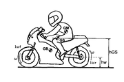
図6には、車両単体における重心位置(GB)とライダーの重心位置(GM)並びにそれら2つの合成重心(GS)及び 合成重心高(hGS)が図の様に示される。
走行時であれば、合成重心の前後にあるタイヤには走行速度、即ちホイールの回転に応じた角運動量(I・ω)が存在する。 ここで記述されるIは、タイヤ軸を中心軸とした回転による慣性モーメントであり、走行から生じたタイヤ回転速度ωであり角速度である。
前輪には I・ωf、後輪にはI・ωr とし存在し 合成重心(GS)は車輪から発生するジャイロ効果に はさまれた位置関係にあることから 車両の安定走行が可能となっている。 ジャイロ効果については、後述する。
FIG. 6 shows the center of gravity position (GB) and the rider's center of gravity position (GM) as well as the two combined center of gravity (GS) and combined center of gravity height (hGS) as shown in the figure.
When traveling, tires around the center of gravity have a traveling speed, that is, an angular momentum (I · ω) corresponding to the rotation of the wheel. I described here is a moment of inertia by rotation about the tire axis as a center axis, and is a tire rotation speed ω and angular speed generated from running.
It exists as I · ωf on the front wheels and I · ωr on the rear wheels, and the combined center of gravity (GS) is in a positional relationship sandwiched by the gyro effect generated from the wheels, so that the vehicle can run stably. . The gyro effect will be described later.
高さ方向に着目すれば、ホイール中心の高さ(hw)と合成重心(GS)の高さ(hGS)の関係が hw < hGS 関係にあることで 車両全体が旋回の際 慣性モーメントとして働き、車両の安定化と運動性能の向上に役立つのである。 Focusing on the height direction, the relationship between the height of the wheel center (hw) and the height of the composite center of gravity (GS) (hGS) is hw <hGS. It helps to stabilize the vehicle and improve motion performance.
日本には、古くから「起き上がりこぶし」や「逆さゴマ」と呼ばれる歴史ある遊具が存在しているが、この遊具を例にとれば、回転する中心よりも回転体の重心が上位位置に位置することが回転物体における安定状態であることから説明できる。 詳しい説明は、専門書に委ねることにするが、 hw > hGS の逆の位置関係になると 一度旋回の為に車両を傾斜させその状態を維持することや、一度倒し込むと傾斜を倒立方向に起こしにくくなり 運動性能が悪化してしまうことになる。 In Japan, there has been a long-standing playground equipment called “Rise Up Fist” or “Inverted Sesame”, but taking this playground equipment as an example, the center of gravity of the rotating body is positioned higher than the center of rotation. This can be explained by the fact that this is a stable state in a rotating object. The detailed explanation will be left to a specialist book. However, if hw> hGS, the vehicle will be tilted once for a turn to maintain its state, and once tilted, the tilt will be inverted. It becomes difficult and exercise performance deteriorates.
以上のことから、車両における重心の位置関係が ライダーのコントロールに対する負担を少しでも低減できるよう 重要な設計配慮が様々されている。 From the above, there are various important design considerations so that the position of the center of gravity in the vehicle can reduce the burden on the rider's control.
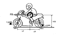
図7は、車両走行時のブレーキによる荷重移動が示されている。
図には、合成重心(GS)から前輪タイヤ中心軸までの距離(LF)、後輪タイヤ中心軸までの距離(LR)が図示される。 この重心(GS)からタイヤ中心までの距離(LF、LR)によって重心での荷重配分が決定され、 前輪にはWNf 後輪にはWNr の荷重が発生する。
走行中の車両にブレーキが掛かると、それに伴う車両の減速G(Gαb)が発生する。
この発生する減速G(αb)に応じた力が、重心へ荷重移動する力(FB) として働き FB=GS×Gαb として働く。 この力、FBにより後から前への回転モーメント(一般的にピッチ方向と呼ばれる)として作用し 前後輪の荷重変化 ΔWBが発生する。
FIG. 7 shows load movement due to braking during vehicle travel.
The figure shows the distance (LF) from the composite center of gravity (GS) to the front tire central axis and the distance (LR) to the rear tire central axis. The load distribution at the center of gravity is determined by the distance (LF, LR) from the center of gravity (GS) to the center of the tire, and a load of WNr is generated on the front wheels and WNr on the rear wheels.
When a brake is applied to a traveling vehicle, a deceleration G (Gαb) of the vehicle is generated.
The force corresponding to the generated deceleration G (αb) works as a force (FB) for moving the load to the center of gravity, and works as FB = GS × Gαb. This force, FB, acts as a rotational moment from the rear to the front (generally called the pitch direction), and a load change ΔWB occurs on the front and rear wheels.
ΔWB= FB×hGS/L =GS×Gαb×hGS/L
として算出できる。
ΔWB = FB × hGS / L = GS × Gαb × hGS / L
Can be calculated as
ここで、hGSは合成重心の高さであり Lはホイールベース長であり L=LF+LR で表現される。
この発生した荷重変化により、前輪には ΔWBの荷重が増え、後輪にはΔWBの荷重が減る。
Here, hGS is the height of the combined center of gravity, L is the wheelbase length, and is expressed as L = LF + LR.
Due to this generated load change, the load of ΔWB increases on the front wheels, and the load of ΔWB decreases on the rear wheels.
ライダーを乗せた停止車両の前輪支持点荷重をWNf、後輪支持点荷重をWNrとし、制動時の前輪支持点荷重をWf、後輪支持点荷重をWrとするとき その関係を式で表せば、 Wf=WNf+ΔWB
Wr=WNr−ΔWB
となる。
When the front wheel support point load of a stopped vehicle with a rider is WNf, the rear wheel support point load is WNr, the front wheel support point load during braking is Wf, and the rear wheel support point load is Wr, , Wf = WNf + ΔWB
Wr = WNr-ΔWB
It becomes.
本提案が示す実施例では、前輪後輪のアブソーバー部にアブソーバーの伸縮を測定できるストロークセンサーを取り付けた車両にて 停止時から走行時の前後荷重配分をリアルタイムに測定することが可能である構成を示している。 走行中にトータル荷重が変化することがない事を考慮すれば、 前後加速度と駆動力または制動力から荷重移動量の算出や重力の推定の算出が可能であり、ストロークセンサーを取り除くことが可能である。 In the embodiment shown in this proposal, the configuration is such that the front and rear load distribution at the time of running from a stop can be measured in real time on a vehicle in which a stroke sensor capable of measuring the expansion and contraction of the absorber is attached to the absorber part of the front and rear wheels. Show. Considering that the total load does not change during driving, it is possible to calculate the amount of load movement and the estimation of gravity from the longitudinal acceleration and driving force or braking force, and it is possible to remove the stroke sensor. is there.
具体的な方法として、加速時の重量推定方法は 特開2002−340165、特許第3821001号、減速時の重量推定方法は 特開2006−337087 など多くの先出願が提案されており、詳細は割愛する。 As specific methods, many prior applications such as Japanese Patent Laid-Open No. 2002-340165 and Japanese Patent No. 3821001 for weight estimation during acceleration and Japanese Patent Laid-Open No. 2006-337087 for weight estimation during deceleration have been proposed. To do.
ここで説明した図7により、前記した図3 ECU内部ブロック図の推定軸荷重を算出することが説明される。 FIG. 7 described here explains that the estimated axial load in the above-described FIG. 3 ECU internal block diagram is calculated.
図8(a)は、傾斜走行中の車両を後ろから見たものであり、重心に掛かる荷重(GS)を示したものである。
旋回中の重心点GSには、前記したように 2つの力 重力による鉛直方向の力(=GS×g)と 遠心力(αc)による力 (=GS×αc) が発生している。
FIG. 8 (a) is a view of a vehicle running on an inclination when viewed from behind, and shows a load (GS) applied to the center of gravity.
At the center of gravity GS during turning, as described above, two forces are generated: a vertical force due to gravity (= GS × g) and a centrifugal force (αc) (= GS × αc).
理論的には この2つの力が傾斜走行中の重心GSに掛かると考える。 この2つの力のベクトル合成の力(Frun)を表せば、バイクが倒立時に近い状態では車体中心線(GS→b)にそって荷重が路面を押しつける力 Frun となる。 しかしながら、傾斜状態となると 倒立時の路面接地点bから接地点は移動し 路面接地点aへ移動していく。 バンク角(Φ)が大きくなるほど移動距離は大きくなる。 すなわち、車両重心(GS)にかかる合成力(Frun)は バンク角に応じ角度ずれが生じる。 車両重心(GS)は、ライダーを含めた車両重心であることから ライダーが傾斜走行時にとる姿勢(リーンアウト等)により変化するため定義しにくい。 Theoretically, it is considered that these two forces are applied to the center of gravity GS during running on an inclination. Expressing the force (Frun) of the vector of these two forces, the load is the force Frun that pushes the road surface along the vehicle body center line (GS → b) when the motorcycle is close to the inverted position. However, when inclining, the ground contact point moves from the road contact point b at the time of inversion and moves to the road contact point a. The greater the bank angle (Φ), the greater the travel distance. In other words, the resultant force (Frun) applied to the vehicle center of gravity (GS) varies depending on the bank angle. Since the vehicle center of gravity (GS) is the center of gravity of the vehicle including the rider, it is difficult to define because it changes depending on the posture (lean out, etc.) that the rider takes when traveling in an inclined manner.
ここで説明される 車体中心線とは、「請求項1」に記述される車体中心線と同意語である。
The vehicle body center line described here is synonymous with the vehicle body center line described in "
図8(b)は、傾斜角について定義したものである。
車体中心線(一点破線)と重力加速度gの加わる垂直線との角度を 車体の理論傾斜角(Φ)と定め 走行時に重心から車両荷重が路面接地点に加わる荷重点aによる傾斜戻り角(ρ)と定め、 Φとρの関係は 車両及びタイヤにより特有の関係が示される。 簡略化するために、ρはΦの一次関数と定義し ρ=Φ(1−Kp)として表記すれば、実傾斜角(Φ−ρ)は、 Φ−ρ=Φ・Kp と定義し 表すことができる。
FIG. 8B defines the tilt angle.
Body center line (dashed line) and the gravitational acceleration g tilt back angle vehicle load angle from the center of gravity when traveling defined body of theoretical inclination and ([Phi) between the vertical lines due to the load point a applied to the road surface ground point applied with ([rho ), And the relationship between Φ and ρ is specific to the vehicle and tire. For simplicity, ρ is defined as a linear function of Φ, and expressed as ρ = Φ (1-Kp), the actual inclination angle (Φ−ρ) is defined as Φ−ρ = Φ · Kp. Can do.
車両に搭載されるハイブリッドセンサー20 は センサー取付け高さ(hsen)での車両挙動を検出する。 前記した、傾斜角速度センサー22 は単位時間あたりの角度変化(rad/sec)を示すものであるから、時間積分を算出した値は角度を示す。
The
この角度は、車体の理論傾斜角(Φ)を検出するものであり、実際の傾斜角Φeは
Φe=Φ−ρ=Φ・Kp であるため、係数をかけなければならない。 実際の角度は理論角度より小さいものであるため 実角度(Φe)<理論角度(Φ) の関係にあることから 補正係数Kpは Kp≦1 として取り扱うことができる。 ある二輪車の経験値であるが KP=0.85程度であることがわかっている。
This angle is for detecting the theoretical tilt angle (Φ) of the vehicle body, and since the actual tilt angle Φe is Φe = Φ−ρ = Φ · Kp, a coefficient must be applied. Since the actual angle is smaller than the theoretical angle, the relationship of the actual angle (Φe) <theoretical angle (Φ) is satisfied, so that the correction coefficient Kp can be handled as Kp ≦ 1. Although it is an experience value of a certain motorcycle, it is known that KP = 0.85.
本説明では、戻り角度(ρ)は Φの一次関数であることから説明してきたが 幅広タイヤの場合や 車両重量が大きく変化する場合などは 角度によって比例定数とならない場合も考えられるため 必要に応じ 係数Kpを 角度Φの変数としてテーブル化した補正係数形態を用いることも可能であり 自由な補正カーブの設定が可能であることを付け加えておく。 In this explanation, the return angle (ρ) has been explained as a linear function of Φ. However, in the case of wide tires or when the vehicle weight changes greatly, it is possible that the proportional constant may not be used depending on the angle. It is also possible to use a correction coefficient form in which the coefficient Kp is tabulated as a variable of the angle Φ, and it is added that a free correction curve can be set.
図8(b)で定義された、接地面の移動(b→a)距離(Δab)と図8(a)で定義された路面押付け力(Frun)の積算をとり、 オーバーターニングモーメントMotが定義でき Mot=Δab×Frun と表現できる。 The overturning moment Mot is defined by integrating the distance (Δab) of the contact surface movement (b → a) defined in Fig. 8 (b) and the road surface pressing force (Frun) defined in Fig. 8 (a). And can be expressed as Mot = Δab × Frun.
このオーバーターニングモーメントは、タイヤ幅が太くなるほど大きくなり ライダーを含めた合成重心高が低くなるほど小さくなる。 Motが大きいと 傾斜しづらいと言ったり 傾斜時に安定度が高いと言ったりして 表現される場合がある。 また、タイヤの空気圧が低いとタイヤの横ずれ量が大きくなってしまい傾斜しにくくなる。 この特性は、二輪車を傾斜していく際の傾斜フィール、安心感などの走行操縦の安定性の善し悪しを決める重要な要因になっている。 詳細については、特開平11−245615 に譲ることとする。
ここで、オーバーターニングモーメント Mot=Δab×Frun の要素Frunは、2つのベクトル 重力と遠心力の合成になっており 遠心力αcは 前記したように
αC=V^2/R に関連する。
図8(a)に戻り説明する。 図に示される遠心力(αc)を車体バンク角(Φ)で傾斜する二輪車に取り付けられた Gセンサー23 から、傾斜とGセンサーの関係を関連づけし 分析することはできない。
すなわち、実際にテストしてみると傾斜角から求めるGセンサーの値と走行時のGセンサーの値は一致しない状況に陥るが、過去多くの先願がこの方法で公開されている。
この一致しない状況において、本出願は解析し一致する演算式を導くことができた。
This overturning moment increases as the tire width increases and decreases as the combined center of gravity including the rider decreases. If the mot is large, it may be expressed that it is difficult to incline or that the stability is high when inclining. In addition, when the tire air pressure is low, the amount of lateral deviation of the tire increases, and the tire does not easily tilt. This characteristic is an important factor in determining whether the stability of driving control is good or bad, such as an inclination feel and a sense of security when the motorcycle is inclined. Details will be given to JP-A-11-245615.
Here, the element Frun of the overturning moment Mot = Δab × Frun is a combination of two vectors gravity and centrifugal force, and the centrifugal force αc is related to αC = V ^ 2 / R as described above.
Returning to FIG. From the G sensor 23 attached to the two-wheeled vehicle that inclines the centrifugal force (αc) shown in the figure at the vehicle body bank angle (Φ), the relationship between the inclination and the G sensor cannot be correlated and analyzed.
That is, when actually testing, the value of the G sensor obtained from the inclination angle does not match the value of the G sensor at the time of traveling, but many prior applications have been published in this way.
In this inconsistent situation, the present application was able to analyze and derive a coincident arithmetic expression.
図9で説明する。 図は、車両に搭載されたハイブリッドセンサー20 と センサー20 が走行時に発生する車両のロール速度、すなわち傾斜角速度(Ψ)の変化 及び 傾斜により発生するバンク角(Φ)、傾斜戻り角(ρ)、バンク角(Φ)と戻り角(ρ)から図示される実傾斜角(Φe)、と 前記されるセンサー20に搭載される 横方向の加速度センサー23 の検出を解析するベクトルが表記される。
一致しない要因は少なくても 4つ存在して折り説明する。
This will be described with reference to FIG. The figure shows the roll speed of the vehicle generated by the
There are at least four factors that do not agree, so I will explain it.
第一要因として、Gセンサーから傾斜角を算出する方法の問題点として 紙面上に傾斜時のベクトルを記入する際 重力ベクトル(g)と バンク角(Φ)に応じた合成ベクトル(A)を記入する従来の方法では 実際の発生する遠心力ベクトル(B)が抜け落ちてしまい正確に表現できていないものがある。
すなわち、紙面上では 停止時の傾斜と走行時の傾斜は同一とみなしており 走行時に発生する実際の遠心力とバランスされる関係が考慮されない点にある。
もしくは、停止時の重力ベクトル(g)と遠心力ベクトル(B)は表記されても実車に搭載されるGセンサーの検出軸Gken(図中の破線)にベクトル投影する際 重力成分ベクトル(C)は投影しても 遠心力成分ベクトル(D)を投影しない ベクトルの抜けが生じるところに問題がある。
The first factor is the problem of the method of calculating the tilt angle from the G sensor. When entering the vector at the time of tilt on the paper, enter the gravity vector (g) and the composite vector (A) corresponding to the bank angle (Φ). In some conventional methods, the centrifugal force vector (B) that is actually generated falls off and cannot be accurately expressed.
In other words, on the page, the inclination at the time of stopping and the inclination at the time of traveling are regarded as the same, and the relationship balanced with the actual centrifugal force generated during traveling is not considered.
Alternatively, when the gravity vector (g) and the centrifugal force vector (B) at the time of stop are expressed, when the vector is projected onto the detection axis Gken (dashed line in the figure) of the G sensor mounted on the actual vehicle, the gravity component vector (C) Does not project the centrifugal force component vector (D) even if it is projected.
第二要因として、要因1を解決し遠心力のベクトルをGセンサーの検出軸Gkenにベクトル投影すると重力の検出ベクトル(C)と 遠心力の検出ベクトル(D)は180度方向の異なる同一ベクトルであるため ベクトルは相殺され 検出軸Gken方向でのベクトルは発生せず「ゼロ」となり 傾斜時には検出Gは発生しないことになってしまう。
その原因は、走行時のバイクは遠心力を相殺するために傾斜バランスをしているため検出されないことと誤解されてしまい 実際に検出される出力値は誤差として扱うことがあげられる。
As the second factor, if
The reason is that it is misunderstood that it is not detected because the motorcycle during running has a tilt balance to cancel the centrifugal force, and the output value actually detected is treated as an error.
第三の要因として、センサーが取り付けられている場所の高さ(hsen) 及び 車両が左右にロールした際の検出場所での速度の変化を加味しないことである。 すなわち、Gセンサーは加速度を検出するものであり 検出センサー自身が加速度の影響を直接うけるため その主要因であるロール速度(Φ)の変化を取り除かない点があげられる。 The third factor is not taking into account changes in the height (hsen) of the location where the sensor is installed and the speed at the detection location when the vehicle rolls left and right. In other words, the G sensor detects acceleration, and the detection sensor itself is directly affected by acceleration, so the change in roll speed (Φ), which is the main factor, is not removed.
第四の要因として、前述した 理論角度Φとタイヤに荷重の掛かる実角度Φe の違いすなわち 傾斜の戻り角(ρ)を加味しないことである。
以上の4点を加味することで、車両挙動の検出として 走行時に発生する傾斜時の横方向加速度を検出する加速度センサー23 を車両挙動検出センサーとして用いることが出来るようになる。
The fourth factor is that the difference between the theoretical angle Φ and the actual angle Φe on which the load is applied to the tire, that is, the inclination return angle (ρ) is not taken into account.
By taking the above four points into consideration, the acceleration sensor 23 that detects the lateral acceleration at the time of inclination that occurs during traveling can be used as the vehicle behavior detection sensor.
実際の検出を図9でさらに説明し検出式の誘導をする。
車体の挙動を検出するためにハイブリットセンサー20 が、車両倒立時の車体中心線(図中の一点破線)にレイアウトされる。 ハイブリットセンサー20 には、進行方向の加速度を検出する加速度センサー21、 進行方向ロール速度を検出する傾斜角速度センサー22 及び ロール方向の加速度を検出する加速度センサー23 が小型に内蔵されおり、ライダーの体重を含めた合成重心に近いところにレイアウトされる。 ハイブリットセンサー20 には、傾斜時に生じる理論バンク角(Φ)及び傾斜によってタイヤでの荷重接地点変化から生じる戻り角(ρ)が同時に存在している。(図8も同時参照)
センサー20 に生じる力(ベクトルA)と 実際に生じる力(ベクトルA’)とは ずれが生じている。 このずれ角(戻り角(ρ))によって、正確な横Gを検出することが解析された。
戻り角は、横Gセンサーで検出される横G値検出に直結する角度のことであり、傾斜走行時のタイヤの路面接地点が直進走行からの移動から生じ定められる角であることが(図8b))及び(図9)のρで表される角度である。 この戻り角は、車体の傾斜角に伴うものであり、直進路走行時は発生せず傾斜角(Φ)の一次関数で定義されることが(0049)に記述されている。
(図8b))により、戻り角を規定する車両上における構成要素は、鉛直線と、車体中心を示す車体中心線と、車体中心線上にあり横Gセンサーが取り付けられている場所の高さポイント(Phsen)、直進時のタイヤの路面接地点の中心のポイント(b)と、傾斜時のタイヤの路面接地点の中心のポイント(a)から規定される。
The actual detection will be further explained with reference to FIG.
In order to detect the behavior of the vehicle body, the
There is a difference between the force (vector A) generated in the
The return angle is an angle directly connected to the lateral G value detection detected by the lateral G sensor, and it is determined that the road contact point of the tire during the inclined traveling is determined by the movement from the straight traveling (see FIG. 8b)) and the angle represented by ρ in FIG. It is described in (0049) that this return angle is associated with the inclination angle of the vehicle body and does not occur when traveling on a straight road and is defined by a linear function of the inclination angle (Φ).
(FIG. 8b)), the components on the vehicle that define the return angle are the vertical line, the vehicle body center line indicating the vehicle body center, and the height point on the vehicle body center line where the lateral G sensor is attached. (Phsen) is defined from the center point (b) of the road surface contact point of the tire when traveling straight and the center point (a) of the road surface contact point of the tire when inclined.
走行中のハイブリットセンサー20 には、路面との距離hsenがあり 車両が左右にロール(ロール速度は角速度検出値(Ψ))することで センサーはタイヤを軸とする円周上の軌跡を通過することになるが 角速度センサー22 の変化は円周上の軌跡上の速度変化として発生する。 すなわち、速度変化は加速度であるから 加速度センサー23 に重畳され検出されるため 角速度による補正項を減算する必要がある。
以上のことから、走行傾斜時に検出されるべく横G(Gken)の考え方は、
Gken = (ベクトル(C))−(ベクトル(D’))−(Ψ) となる。
The running
From the above, the concept of lateral G (Gken) to be detected when the vehicle is tilting is
Gken = (vector (C)) − (vector (D ′)) − (Ψ).
それぞれのベクトルを式として表せば
Gken = (g・sinΦ)−{A’・cos(90−Φ+ρ)}・cosΦ
−(Ψ・Rsen)
式を整理し
Gken =g{sinΦ−tan(Φ−ρ)・cosΦ}−Ψ・Rsen
ρは、前記したように Φの一時関数とするとき
Gken =g{sinΦ−tan(Φ・Kp)・cosΦ}− Ψ・Rsen
を導くことができる。
If each vector is expressed as an equation, Gken = (g · sinΦ) − {A ′ · cos (90−Φ + ρ)} · cosΦ
-(Ψ ・ Rsen)
Gken = g {sinΦ-tan (Φ−ρ) · cosΦ} −Ψ · Rsen
ρ is a temporary function of Φ as described above. Gken = g {sinΦ−tan (Φ · Kp) · cosΦ} − Ψ · Rsen
Can guide you.
この式の g{sinΦ−tan(Φ・Kp)・cosΦ} の部分は、重力成分と遠心力成分の差分を求める構成になっているため、直接 傾斜の戻り角から求める式に変換すれば、
Gken = g・cosΦ・tanρ − Ψ・Rhen
と変形でき、シンプルな式になる。
ここで、表されるΦは 車両の理論バンク角度であり理論傾斜角でもある、 傾斜角速度センサー22 から検出される角速度Ψ(rad/sec) を時間積分して得られた角度であり、ρは傾斜戻り角であり、RはGセンサー#23の実車取付けの高さ(図8b hsen )をそれぞれ示している。
ここでのセンサーの配置と検出について明確にする。
センサーの配置については、(0061)文中にも「・・・路面との距離hsenがあり、センサーはタイヤを軸とする円周上軌跡を通過する・・・」ことが(0062)式の「・・・(Ψ・Rsen)」で記述される。 センサーの検出方向としての軸は、横方向の加速度であり、(図8b))及び(図9)のGkenが示す方向であり、前記の円周との接線といえる。 すなわち、車体の倒立が鉛直線と一致するとき車体中心線は鉛直線と重なり、円周上の半径hsenで定まる高さのポイントも前記の接線も一点で合致し横加速度補正に用いるRsenは理想に近づく。 しかしながら、センサーの実車への配置が車体中心線から離れると円周上の軌跡とGセンサーの検出方向(接線)とが離れていく事象が生じることから、Rsenとhsenが等しくならず無視できない状況に陥ると傾斜角度による補正などが必要になってくる。 よって、センサー配置は重心位置近くであり車体中心線上にあるのが望ましい。
The g {sinΦ-tan (Φ · Kp) · cosΦ} part of this equation is configured to obtain the difference between the gravity component and the centrifugal force component, so if converted directly to the equation obtained from the return angle of the slope,
Gken = g ・ cosΦ ・ tanρ − Ψ ・ Rhen
Can be transformed into a simple expression.
Here, Φ is a theoretical bank angle and a theoretical tilt angle of the vehicle, and is an angle obtained by integrating the angular velocity ψ (rad / sec) detected by the tilt
Clarify sensor placement and detection.
Regarding the arrangement of the sensor, in the text (0061), “... there is a distance hsen with the road surface, and the sensor passes a trajectory on the circumference around the tire ...” ... (Ψ · Rsen) ”. The axis as the detection direction of the sensor is the acceleration in the lateral direction, the direction indicated by Gken in (FIG. 8b) and (FIG. 9), and can be said to be a tangent to the circumference. That is, when the inversion of the vehicle body coincides with the vertical line, the vehicle body center line overlaps the vertical line, and the height point determined by the radius hsen on the circumference and the tangent line coincide at one point, and Rsen used for lateral acceleration correction is ideal. Get closer to. However, when the sensor is placed away from the center line of the vehicle, there is an event that the locus on the circumference and the detection direction (tangent) of the G sensor are separated, so Rsen and hsen are not equal and cannot be ignored. If it falls into, it will be necessary to correct by tilt angle. Therefore, it is desirable that the sensor arrangement be near the center of gravity position and on the vehicle body center line.
g・cosΦ・tanρ を第一項とし、Ψ・Rhsen を第二項として説明する。 In the following description, g · cosΦ · tanρ is a first term and Ψ · Rhsen is a second term.
式の内容を分析すれば、第一項は傾斜角(Φ)および 戻り角(ρ)から一義的に求められる基準横Gであり、規範横Gと呼べる。 第二項は、ロールによる補正項である。 If the contents of the equation are analyzed, the first term is the reference lateral G that is uniquely determined from the tilt angle (Φ) and the return angle (ρ), and can be called the standard lateral G. The second term is a correction term by the roll.
以上を整理しなおすと、傾斜により発生する規範横G(Gkihan)は
その式の書き方により
Gkihan = g{sinΦ−tan(Φ・Kρ)・cosΦ}
= g{sinΦ−tan(Φ−ρ)・cosΦ}
= g・cosΦ・tanρ
と変形でき 使用しやすい形態を選択すればよい。
この式を導くために、実際の二輪車に搭載した角速度センサーから 理論バンク角(Φ)を傾斜角速度(Ψ)の時間積分による説明で誘導してきたが 上記式である
Gkihan = g{sinΦ−tan(Φ−ρ)・cosΦ}
= g・cosΦ・tanρ
には、傾斜角速度のパラメータは存在しておらず 理論バンク角(Φ)と傾斜戻り角(ρ)により、一義的に求められることが明確である。
ここでのGkihanとは、理論検出横Gであり、「二輪車の傾斜時に発生する理論検出G(規範Gと呼べる)を導く理論式・・・車両挙動の判断とするための基準・・・」であることが(0011)にも記述される。 この傾斜時とは、走行時に発生する角度であり、その際に横加速度が発生しセンサーより検出される値が検出Gであり、理論とはバンク角であり理論傾斜角を意味している。
To re-arrange the above, the standard lateral G (Gkihan) generated by the inclination depends on how to write the equation.
Gkihan = g {sinΦ-tan (Φ · Kρ) · cosΦ}
= G {sinΦ-tan (Φ-ρ) · cosΦ}
= G ・ cosΦ ・ tanρ
You can select a form that can be deformed and easy to use.
In order to derive this equation, the theoretical bank angle (Φ) has been derived from the angular velocity sensor mounted on the actual two-wheeler by the explanation based on the time integration of the tilt angular velocity (Ψ). Φ−ρ) · cosΦ}
= G ・ cosΦ ・ tanρ
It is clear that there is no parameter of tilt angular velocity, and it can be determined uniquely by the theoretical bank angle (Φ) and tilt return angle (ρ).
Here, Gkihan is the theoretical detection lateral G, and “theoretical formula that leads to the theoretical detection G (which can be called the norm G) that occurs when the two-wheeled vehicle is tilted—a criterion for determining vehicle behavior” It is also described in (0011). The inclination is an angle generated during traveling, and a value detected by the sensor when lateral acceleration is generated at that time is a detection G. The theory is a bank angle and means a theoretical inclination angle.
「請求項1」で記載される、
車両に搭載された車両傾斜角度検出機能により、車体中心線と鉛直線との成す傾斜角度を検出 又は算出された理論バンク角度(Φ)及び 直進走行時のタイヤ路面接地点と傾斜走行時のタイヤ路面接地点の位置移動によって定義される理論バンク角の傾斜戻り角(ρ)より、理論バンク角から傾斜戻り角を減算した実バンク角(Φ−ρ)値を算出し、走行時に発生する左右横方向加速度の理論検出横G(Gkihan)を式、
Gkihan= g{sinΦ−tan(Φ−ρ)・cosΦ}
または
Gkihan= g・cosΦ・tanρ
から 傾斜時に発生する横Gの算出を傾斜角から求める機能を備えることを特徴とする自動二輪車の横方向加速度の規範値検出に関する検出方法。は、
上記「0066」で説明される様に 傾斜角速度のパラメータは存在しておらず 理論バンク角(Φ)と傾斜戻り角(ρ)により、一義的に求められることから一般式化している。 よって、理論バンク角を求める手段は無数に存在するため、「車両傾斜角度検出機能」と表現し、その検出方法について限定することを取り除いた。 同様の意味で、直接角度を検出できるセンサーでも 本実施例で説明してきたような角速度の時間積分により算出される角度でも角度を検出することは可能であるから、センサーの出力形態を問わず検出方法を限定する表現を取り除いた。
「車体中心線と鉛直線との成す角度」と表現したのは、直進走行時に倒立した状態を理論バンク角(Φ)ゼロ度とおき、重力加速度の向きと一致させることで、左右方向の実傾斜角(Φe)を求める際の減算(Φ−ρ)の部分の演算を単純化するために(Φ・Kρ)と置き換えるができる形態とした。
As described in “
The tilt angle formed by the vehicle center line and the vertical line is detected or calculated by the vehicle tilt angle detection function installed in the vehicle. The calculated theoretical bank angle (Φ) and the tire road surface contact point during straight travel and the tire during tilt travel The actual bank angle (Φ-ρ) value obtained by subtracting the inclination return angle from the theoretical bank angle is calculated from the theoretical bank angle inclination return angle (ρ) defined by the movement of the road surface contact point. Theoretical detection of lateral acceleration lateral G (Gkihan)
Gkihan = g {sinΦ-tan (Φ-ρ) · cosΦ}
Or
Gkihan = g ・ cosΦ ・ tanρ
A detection method for detecting a normative value of a lateral acceleration of a motorcycle, comprising a function of calculating a lateral G generated when the vehicle is inclined from an inclination angle. Is
As explained in “0066” above, there is no tilt angular velocity parameter, and it is generalized because it is uniquely determined by the theoretical bank angle (Φ) and tilt return angle (ρ). Therefore, since there are an infinite number of means for obtaining the theoretical bank angle, it is expressed as “vehicle inclination angle detection function” and the detection method is not limited. In the same sense, even a sensor that can directly detect an angle can detect an angle even with an angle that is calculated by integrating the angular velocity as described in this embodiment, so detection is possible regardless of the output form of the sensor. Removed language limiting method.
The expression “the angle between the car body center line and the vertical line” is expressed as the left and right sides of the actual vehicle in the left-right direction by matching the direction of gravity acceleration with the theoretical bank angle (Φ) set to zero degrees when the vehicle is turned straight. In order to simplify the calculation of the subtraction (Φ−ρ) portion when obtaining the tilt angle (Φe), it can be replaced with (Φ · Kρ).
式の本質である 傾斜時に車体に搭載された横Gセンサーに検出される規範横Gを求める Gkihan= g{sinΦ−tan(Φ−ρ)・cosΦ}
= g・cosΦ・tanρ
は、傾斜戻り角は存在するものの、表1で説明された 遠心力はバンク角度に依存する と矛盾しておらず 昔から慣れ親しんだ 遠心力 α= V^2/r の事象を捉えるものである。
It is the essence of the equation. Obtain the reference lateral G detected by the lateral G sensor mounted on the vehicle body when tilting. Gkihan = g {sinΦ-tan (Φ-ρ) · cosΦ}
= G ・ cosΦ ・ tanρ
Although there is an inclination return angle, the centrifugal force described in Table 1 is consistent with the bank angle, and it is not contradictory. .
このことから、傾斜角に変化が生じない状況であれば、検出される横G(Gken)=理論検出横G(Gkihan)であることがわかる。 また、傾斜角は(0004)に記述される様に車体の一部が接地するほど傾斜角の範囲が存在しているため、傾斜角の範囲全体に渡り理論検出横Gが存在していることが容易にわかる。
この式で表現される 傾斜戻り角(ρ)の測定方法は 様々考えられるが 二輪車の仕様によって定められるタイヤ選択から決定される因子が強い。
よって、3つの計測方式を列記しておく。
From this, it can be seen that the detected lateral G (Gken) = theoretical detected lateral G (Gkihan) if the tilt angle does not change. In addition, as described in (0004), since the tilt angle range exists as a part of the vehicle body comes in contact with the ground, the theoretical detection lateral G exists over the entire tilt angle range. Is easily understood.
There are various ways to measure the tilt return angle (ρ) expressed by this formula, but there are strong factors determined by the tire selection determined by the specifications of the motorcycle.
Therefore, three measurement methods are listed.
測定方法1、 実際に車両を走行させ 様々な傾斜角にバンクさせた画像を取り込み、取り込んだ画像解析により 角度に応じた傾斜戻り角(ρ)の値を得る方法である。
測定方法2、 式 Gkihan= g・cosΦ・tanρ を変形し、 ρ=TAN^1 (Gkihan/g・cosΦ) で変形されるアークタンジェント(TAN^1)の値を逆算し 傾斜戻り角(ρ)の値を得る方法である。
測定方法3、 ホイールの中心軸に直接 6分力計などのセンサーを直接用いる方法である。
続いて、制御装置として構築する方法に移る。
実際の走行傾斜時に検出される検出横G(Gken)は、傾斜角の時間的変化である傾斜角速度(Ψ)を用いた補正が必要であることから 補正後の横G(Ghosei)は
Ghosei = Gken−(Ψ・Rhsen)
として表される。
この補正後の横G(Ghosei)は、
(0063)式のGkenから傾斜角速度(Ψ)を用いた補正であり、(0067)の式に対して、傾斜角が変化しない状況である。 すなわち、式の「Ψ・Rhsen」の項については、ゼロとなることから二つの式を整理し記述すると、上記のGhoseiの等号式は、
Ghosei=Gken=g・cosΦ・tanρ=理論検出横G(Gkihan)
の関係となる。 この様に、式の「Ψ・Rhsen」の項について、ゼロにしたデーターは、定常円旋回時に得られたデーターと呼ばれることがある。
そして、これらの理論検出横Gの上記等号式に関わる上記変数には、傾斜角の範囲全体に渡り、傾斜角に応じ検出される車両特有の横加速度の数値が関係として導かれる。
Then, it moves to the method of constructing as a control device.
The detected lateral G (Gken) detected at the time of actual traveling inclination needs to be corrected using the inclination angular velocity (Ψ), which is the temporal change of the inclination angle, so the corrected lateral G (Ghosei) is
Ghosei = Gken- (Ψ · Rhsen)
Represented as:
The lateral G (Ghosei) after this correction is
This is correction using the inclination angular velocity (Ψ) from Gken in equation (0063), and the inclination angle does not change with respect to equation (0067). That is, regarding the term “Ψ · Rhsen” of the equation, since it becomes zero, when the two equations are arranged and described, the above equation of Ghosei is
Ghosei = Gken = g · cosΦ · tanρ = theoretical detection lateral G (Gkihan)
It becomes the relationship. In this way, the data set to zero for the term “Ψ · Rhsen” in the equation may be referred to as data obtained during steady circle turning.
Then, the above-mentioned variables related to the above equality equation of the theoretically detected lateral G are derived as a relation with the numerical value of the vehicle-specific lateral acceleration detected according to the inclination angle over the entire range of the inclination angle.
補正項として用いている Ψ・Rhsen の部位の影響度は ゆっくりのスラローム走行で発生し得るロール速度の変化を 1秒間に 0→0.25π 「rad/sec」 (45deg/sec)変化だったと想定した場合 発生するG(Grol)は
Grol= 0.25*3.14*1 = 0.785 「m/s^2」
(但し、センサー取り付け高さ Rを1mとする。)
であり、重力加速度 9.81 「m/s^2」 との影響度は 0.785/9.81を算出すると 約8%となり制御を考える際、無視できない項目であることが分かる。
よって、補正の必要性が裏づけされる。
傾斜時の規範横G(Gkihan)と 実際に走行時に発生する補正を行った横G(Ghosei)から、目標値を得るための制御値を求めるには 偏差をとればよい。
すなわち、スムーズで安定した走行でいるときには 前記したように規範Gとなることから 補正後の検出横Gと規範Gとの差分を下記の式から 偏差G(Ghensa)を
Ghensa=Ghosei−Gkihan
求めることができる。
Assuming that the change in roll speed that can occur during slow slalom running is 0 → 0.25π “rad / sec” (45 deg / sec) change per second. In this case, the generated G (Grol) is Grol = 0.25 * 3.14 * 1 = 0.785 “m / s ^ 2”
(However, the sensor mounting height R is 1 m.)
The gravitational acceleration of 9.81 “m / s ^ 2” has an influence degree of about 8% when 0.785 / 9.81 is calculated, and it can be seen that this is an item that cannot be ignored when considering control.
Therefore, the necessity for correction is supported.
In order to obtain a control value for obtaining the target value from the reference lateral G (Gkihan) at the time of inclination and the lateral G (Ghosei) that has been corrected to actually occur during traveling, a deviation may be taken.
That is, when the vehicle is running smoothly and stably, it becomes the standard G as described above. Therefore, the difference between the detected lateral G after the correction and the standard G is calculated from the following equation: Deviation G (Ghensa)
Can be sought.
車両の走行状態を この偏差分の横G(Ghensa)から、後述するアンダーステアー(U.S.)、オーバーステアー(O.S.)、ニュートラルステアー(N.S.)の判断がされ、ブレーキ配分が決定される役割をもっている。 From the lateral G (Ghensa) of this deviation, the vehicle is judged as understeer (US), oversteer (OS), and neutral steer (NS), which will be described later. It has a role to determine allocation.
図10は、旋回状態の二輪車を上部から図示したものでる。
前輪軌跡(A)と後輪軌跡(B)は、旋回時のタイヤ軌跡を表している。 図中の破線は、前輪と後輪の接地面を結ぶ延長線が示してあり 後輪の駆動する方向を示している。
FIG. 10 illustrates a two-wheeled vehicle in a turning state from above.
The front wheel trajectory (A) and the rear wheel trajectory (B) represent tire trajectories during turning. The broken line in the figure shows an extension line connecting the ground contact surface of the front wheel and the rear wheel, and indicates the direction in which the rear wheel is driven.
前輪には、前述したように設定されたキャスター角によるトレールの設定があり 旋回時には傾斜によりタイヤ接地点の変化が生じ その為ハンドルが自動的に操舵する自動操舵機能が備わっている。 よって、表1に記述する様に 旋回時の速度と傾斜角度の関係によってバランスする操舵角度が存在している。 後輪進行方向と前輪進行方向の間には角度差β、後輪は前輪と異なり機械的操舵機構が備わらないため 駆動方向と後輪軌跡の関係に角度差βrの関係が生じ 定義できる。 βを操舵アングルと呼び、βrを後輪のスリップアングルと呼ぶ。 The front wheels have a trail setting based on the caster angle set as described above. When turning, the tire ground contact point changes due to the inclination, so the steering wheel automatically steers. Therefore, as described in Table 1, there is a steering angle that balances depending on the relationship between the turning speed and the inclination angle. The angle difference β between the rear wheel traveling direction and the front wheel traveling direction. Unlike the front wheel, the rear wheel does not have a mechanical steering mechanism, so the relationship between the driving direction and the rear wheel locus can be defined as the angle difference βr. β is called the steering angle, and βr is called the rear wheel slip angle.
前輪は、後輪から発生した駆動力とそのときの車体速度を 角度βをもって旋回外側に飛び出さない様に押さえている。 すなわち、前輪は前輪後方から押される力を操舵によって生じた角度βをつけて 進行方向の向きを変える仕組みになっている。 後輪は、前輪が角度βの角度で進行方向へ向きを変えると 後輪の駆動方向にずれが生じ スリップアングルとして 後輪もスリップ角を生じて進行方向へ向きを変える。 The front wheels hold the driving force generated from the rear wheels and the vehicle speed at that time so that they do not jump out of the turn at an angle β. In other words, the front wheels are configured to change the direction of travel by applying an angle β generated by steering to the force pushed from the rear of the front wheels. When the direction of the rear wheel is changed in the traveling direction by the angle β, the rear wheel is shifted in the driving direction, and the rear wheel also changes its direction in the traveling direction as a slip angle.
一般的なドライ路での走行状態では、旋回半径と走行軌跡 及びスリップアングルに一定の関係が存在している。 バランス状態にある二輪車については、「速度とロールの関係」が存在していることから推定舵角を算出 または データとして持つ事ができ 図3で表される「オーバーターニングモーメントを算出」することが可能となる。
直進時であれば、軌跡(A)と軌跡(B)は同一軌跡を通過するためスリップアングルβrは生じないためゼロになる。 旋回状態となり、倒立状態からバンク角が次第に深くなって行くに従い、軌跡(B)は 軌跡(A)から徐々に離れていき 内側を通過するようになる。 軌跡(A)と軌跡(B)の軌跡半径の差は、走行速度が高いほど軌跡半径の差は小さく 走行速度が低くなると軌跡半径の差は大きくなってくる関係あり、走行速度によって異なってくる。 すなわち、走行速度と傾斜角がわかれば軌道推定をしたり、予めテーブルデータとして用意することが出来る。
スリップアングルβrは、軌跡半径の差が大きいほどスリップアングルが大きい関係となる。 詳細については、後述する。
In general driving conditions on dry roads, there is a certain relationship between the turning radius, the driving trajectory, and the slip angle. For motorcycles in a balanced state, there is a “relationship between speed and roll”, so the estimated steering angle can be calculated or stored as data, and the “overturning moment can be calculated” shown in FIG. It becomes possible.
When traveling straight, the trajectory (A) and the trajectory (B) pass through the same trajectory, and therefore the slip angle βr does not occur and becomes zero. As the bank angle gradually increases from the inverted state, the trajectory (B) gradually moves away from the trajectory (A) and passes through the inside. The difference in trajectory radius between the trajectory (A) and the trajectory (B) is such that the higher the travel speed, the smaller the trajectory radius difference, and the lower the travel speed, the greater the trajectory radius difference. . That is, if the traveling speed and the inclination angle are known, the trajectory can be estimated or prepared as table data in advance.
The slip angle βr has a relationship in which the slip angle increases as the difference in locus radius increases. Details will be described later.
この関係を車両挙動として表現するならば、走行軌跡(A)と走行軌跡(B)が同一な場合をN.S.(ニュートラルステアー)と呼ぶことにする。 走行軌跡(A)より走行軌跡(B)が外側を通過する場合を O.S(オーバーステアー)と呼び、走行軌跡(A)より走行軌跡(B)が内側を通過する場合を U.S. (アンダーステアー)と呼ぶことがある。 そして走行時は、路面状態・速度をはじめ 加速時・減速時・ドリフト時・S字などの切替し時など 走行シィチュエーションにより 時々刻々と変化していく。
その例を図11で説明する
If this relationship is expressed as vehicle behavior, the case where the traveling locus (A) and the traveling locus (B) are the same is referred to as NS (neutral steer). A case where the traveling locus (B) passes outside from the traveling locus (A). This is called S (oversteer), and the case where the travel locus (B) passes inside from the travel locus (A) is sometimes called US (understeer). When driving, the road surface condition, speed, acceleration, deceleration, drift, S-shape switching, etc. will change from moment to moment depending on the driving situation.
An example is illustrated in FIG.
図は、左旋回から右旋回へ傾斜が切り返されるときの様子を示したものである。 図のように、傾斜の切り返しがされると 前輪の軌道は目標軌跡であるターゲットラインにそってトレースすることができるが ときには逆操舵を行いながら通過するときもある。
後輪は横方向にスライドしながら落ち着くべき軌跡N.S.(ニュートラルライン)に収斂される。 これは、走行時に生じるタイヤ回転差の吸収と 後輪タイヤの荷重変化をスムーズに受止めるために発生する横すべり現象である。
The figure shows the state when the inclination is turned back from the left turn to the right turn. As shown in the figure, the front wheel track can be traced along the target line, which is the target trajectory, when the slope is turned back, but sometimes it can pass with reverse steering.
The rear wheel slides sideways and should settle down. S. Converged to (neutral line). This is a side-slip phenomenon that occurs in order to absorb the tire rotation difference that occurs during running and the load change of the rear wheel tires smoothly.
この様な車両挙動を検出するためには、ロール方向の角速度を検出するセンサー22 だけでは不十分であり、ロール方向の横加速度を検出するセンサー23 が必要となる。
前記した様に、ロール方向の角速度を時間積分して理論傾斜角度(Φ)を算出し、傾斜戻り角(ρ)による補正係数(Kp)を用いて実傾斜角(Φe)を求め、実傾斜角に基づいた横加速度の検出が可能となる。
前輪は、後輪に比べ切返しを行っても横滑りが発生しにくいようにハンドル操舵による微調がとれるようキャンバーアングルとよばれる前輪スポーク角の設定で自動調整され、前輪ターゲットラインを通過できる。 しかしながら、前記した様に後輪は走行軌跡の距離の違いから発生するスリップ率を吸収する必要があるため、走行状態によっては横滑りを伴い 前輪ターゲットラインとは異なるもう一つのN.S.軌跡が存在している。 このN.S.ラインを走行すれば、傾斜走行時の重力と遠心力のバランスが取れた状態になることであり 車両挙動としても安定しているとみなしてもよい。 切返しからN.S.ラインまでの車両挙動をアンダーステアー(U.S.)状態、 N.S.ラインで留まらずさらに横滑りが発生する状態であればオーバーステアー(O.S.)状態と定義づけできる。
In order to detect such a vehicle behavior, the
As described above, the theoretical inclination angle (Φ) is calculated by integrating the angular velocity in the roll direction over time, and the actual inclination angle (Φe) is obtained using the correction coefficient (Kp) based on the inclination return angle (ρ). It becomes possible to detect lateral acceleration based on the angle.
The front wheels are automatically adjusted with the setting of the front wheel spoke angle called the camber angle so that a fine adjustment by steering the steering wheel can be made so that the skid is less likely to occur even when the vehicle is turned over compared to the rear wheel, and can pass the front wheel target line. However, as described above, since the rear wheel needs to absorb the slip rate generated due to the difference in the distance of the travel locus, another N.D. S. A trajectory exists. This N.I. S. If you drive along the line, you will be in a state where gravity and centrifugal force are balanced when you drive on an incline. N. S. The vehicle behavior up to the line is understeered (US) state, S. An oversteer (O.S.) state can be defined as long as it does not stay on the line and a side slip occurs.
よって、前記した傾斜規範横Gと補正後の横Gとの差分横G(Ghensa)の式からGhensa=Ghosei−Gkihan を求め 符号の向きにより、 U.S./O.Sの判断が可能になる。 アンダーステアーは、旋回外側に走行軌跡が膨らむため 横Gの発生が少なくなることから Ghosei < Gkihan の関係となり、Ghensaはマイナス符号の向きで判断できる。 逆に、プラス符号となる場合は
Ghosei > Gkihan の関係にあることから、オーバーステアー(O.S.)と判断でき 走行軌跡は小さくなっていく方向になる。
前記したように、アンダーステアーは旋回外側に走行軌跡が膨らむため 車両挙動としてバンク角が深くなる状況では前輪への配分を多くし、バンク角が浅くなる状況では後輪への配分を多くする。
Therefore, Ghensa = Ghosei-Gkihan is obtained from the equation of the difference lateral G (Ghensa) between the inclination reference lateral G and the corrected lateral G, and the U.S. S. / O. S can be determined. Understeer has a relationship of Ghosei <Gkihan because the trajectory swells outside the turn and the occurrence of lateral G is reduced, and Ghensa can be determined by the direction of the minus sign. On the other hand, if it is a plus sign, the relationship is Ghosei> Gkihan, so it can be determined that the vehicle is oversteered (O.S.), and the travel locus becomes smaller.
As described above, understeering causes the travel locus to swell outwardly of the turn, so that the distribution to the front wheels is increased when the bank angle is deep as the vehicle behavior, and the distribution to the rear wheels is increased when the bank angle is shallow.
オーバーステアーは旋回内側に走行軌跡が小さくなっていくため 車両挙動としてバンク角が深くなる状況では前輪への配分を多くし、バンク角が浅くなる状況では後輪への配分を多くする。 いずれも、車両の特性に関係するところが強いことから テーブルデータによるところが強い。 (イメージを図19に表記した)
図19説明に入る。 中央部の天秤にあたるところは、前後輪への制動力配分であり目標油圧の配分でもある。
天秤左側は、目標制動力が入力されるが 補正項として「OTM」「車両重量」「推定軸荷重」など要素で、目標制動力の補正がされる。 天秤右側には、前後輪への配分された目標油圧が出力され 前輪後輪ともにPIDコントローラーによって油圧目標値になる様に電磁バルブとモーターの両方をコントロールする。 油圧フィードバックは、油圧の圧力検出信号であり PIDコントローラーの出力結果でもあるが 油圧系の温度による伝達特性の応答性改善にも使用することができる。
天秤のバランスであり目標の配分にあたる配分比を決定するのが、 Ghensaと傾斜速度変化である角速度(Ψ)である。
Oversteer has a smaller trajectory on the inside of the turn, so when the bank angle becomes deeper as a vehicle behavior, the allocation to the front wheels is increased, and when the bank angle is shallower, the allocation to the rear wheels is increased. Both are strongly related to the characteristics of the vehicle, and so are based on table data. (The image is shown in FIG. 19)
19 will be described. The center balance is the distribution of braking force to the front and rear wheels and the distribution of the target hydraulic pressure.
On the left side of the balance, the target braking force is input, but the target braking force is corrected with factors such as “OTM”, “vehicle weight”, and “estimated shaft load” as correction terms. On the right side of the balance, the target hydraulic pressure distributed to the front and rear wheels is output. Both the front and rear wheels are controlled by the PID controller to control both the solenoid valve and the motor. Oil pressure feedback is a pressure detection signal for oil pressure and is an output result of the PID controller, but it can also be used to improve the response characteristics of the transfer characteristics depending on the temperature of the oil pressure system.
It is Ghensa and the angular velocity (Ψ) that is the change in the inclination velocity that determines the balance ratio and the distribution ratio corresponding to the target distribution.
「請求項2」に記述される、
車両に搭載された車両挙動検出用センサーとして、進行方向に対して左右横方向加速度を検出する加速度センサー 及び 進行方向に対して左右ロール方向角速度を検出する角速度センサーを少なくとも搭載する車両において、
「請求項1」の車両傾斜角度の検出を 角速度センサーから検出された角速度出力(Ψ)の値を時間積分して得られる車体の理論バンク角(Φ) 及び 直進走行時のタイヤ路面接地点と傾斜走行時のタイヤ路面接地点の位置移動によって定義される理論バンク角の傾斜戻り角(ρ)より、理論バンク角から傾斜戻り角を減算した実バンク角(Φ−ρ)値を算出し、走行時に発生する左右横方向加速度を
1)、 傾斜走行時の理論検出横G(Gkihan)を
Gkihan= g{sinΦ−tan(Φ−ρ)・cosΦ}
または
Gkihan= g・cosΦ・tanρ
の式を用いた規範G値の算出、を行う「請求項1」の具現化した算出方法
2)、 走行時に変化する実際の検出横G(Gken)を少なくとも傾斜角の時間微分 (dΦ/dt)値である傾斜角速度(Ψ)を用いた補正を行い、補正後の横G(G hosei)を
Ghosei= Gken−(Ψ・Rhsen)
の式を用いて補正した値の算出G値、
3)、 1)から求めた理論検出横G(Gkihan)と 2)から求めた補正後の 横G(Ghosei)の差分を算出した 偏差横G(Ghensa)を
Ghensa= Ghosei−Gkihan
の式を用いて偏差の値の算出G値、
上記1)、2)、3)から、3種類の横G値 Gkihan、Ghosei、Ghensa、を算出し 車両の挙動を Ghensaの値から、
Ghensa ≒ 0(ゼロ) ならば ニュートラルステアー(N.S.)
Ghensa > 0 (正)ならば オーバーステアー(O.S.)
Ghensa < 0 (負)ならば アンダーステアー(U.S.)
と判断され、 Ghensaの符号と値に基づき 演算式 又はテーブルに従って、前輪後輪へのブレーキ配分が決定される事を特徴とする二輪車のブレーキ装置、
について説明する。
As described in “
As a vehicle behavior detection sensor mounted on a vehicle, in a vehicle equipped with at least an acceleration sensor that detects lateral acceleration in the lateral direction relative to the traveling direction and an angular velocity sensor that detects angular velocity in the lateral roll direction relative to the traveling direction,
The detection of the vehicle inclination angle of “
Gkihan = g {sinΦ-tan (Φ-ρ) · cosΦ}
Or
Gkihan = g ・ cosΦ ・ tanρ
The
Ghosei = Gken- (Ψ · Rhsen)
The calculated G value of the value corrected using the equation of
3) The lateral deviation G (Ghensa) calculated from the difference between the theoretical detection lateral G (Gkihan) obtained from 1) and the corrected lateral G (Ghosei) obtained from 2) is obtained.
Ghensa = Ghosei-Gkihan
G value for calculating the deviation value using the formula
From the above 1), 2), and 3), three types of lateral G values Gkihan, Ghosei, and Ghensa are calculated, and the behavior of the vehicle is calculated from the value of Ghensa.
If Ghensa ≒ 0 (zero), neutral steer (NS)
If Ghensa> 0 (positive), oversteer (OS)
If Ghensa <0 (negative), understeer (US)
A brake device for a two-wheeled vehicle, characterized in that the brake distribution to the front and rear wheels is determined according to an arithmetic expression or a table based on the sign and value of Ghensa,
Will be described.
項目1) は、バンク角によって理想的な横Gが存在しており 車両が安定して走行している際には 表1で示したように安定した遠心力の発生になることから、車両のロールによる角速度の補正項を取り除いた 傾斜と遠心力とのバランス状態を検出することである。 よって、センサーからの検出G(Gken)から補正項を取り除き記述すれば
規範横Gは、 Gkihan= g・cosΦ・tanρ の様に表される。
For item 1), there is an ideal lateral G depending on the bank angle. When the vehicle is running stably, stable centrifugal force is generated as shown in Table 1. This is to detect the balance between the tilt and centrifugal force, excluding the correction term for the angular velocity due to the roll. Therefore, if the correction term is removed from the detection G (Gken) from the sensor and described, the normative lateral G is expressed as Gkihan = g · cosΦ · tanρ.
項目2) は、走行時の傾斜により検出された検出G(Gken)は車両のロールによる誤差が重畳されるため ロール成分を取り除くために角速度の補正を行うことが必要となる。 すなわち、センサーからの検出G(Gken)から規範G成分の部位を実際の検出される横G(Gken)に置換え、角速度による補正を行えば 規範同様にロールによる影響を排除した 補正後の制御で使用できるG(hosei)が導け、
Ghosei=Gken−(Ψ・Rhsen) の様に表される。
ここで補正項として傾斜角速度を加味している理由は、前記したように制御上無視できない要素になっているためである。 その他にもセンサー取り付け高さが加速減速による高さの変化、タイヤ空気圧、タイヤ横ずれ量 等々により変化するなど、補正項は考えられるが重要なものに絞る。
In item 2), since the detection G (Gken) detected by the inclination during traveling is superimposed with an error due to the roll of the vehicle, it is necessary to correct the angular velocity in order to remove the roll component. In other words, if the position of the reference G component is replaced with the actually detected lateral G (Gken) from the detection G (Gken) from the sensor and the correction based on the angular velocity is performed, the influence of the roll is eliminated as in the case of the control after correction. G (hosei) that can be used leads,
Ghosei = Gken− (Ψ · Rhsen)
The reason why the inclination angular velocity is taken into account as a correction term is that it is an element that cannot be ignored in the control as described above. In addition, the correction term is limited to the important ones, such as the sensor mounting height changes due to changes in height due to acceleration / deceleration, tire pressure, tire lateral displacement, etc.
項目3)は、制御量を求めるための記述であり 傾斜角に応じた規範横G(Gkihan)と 実際に検出される横G(Ghosei)との差分がいつも偏差を生じないように
制御値として演算することを意味している。 よって、傾斜時の規範横Gと補正後の横Gとの差分を偏差横G(Ghensa)として式で表し、
Ghensa=Ghosei−Gkihan
を求め制御偏差としている。 この偏差が大きければ、横滑りもしくは急な起きあがり事象 倒れ込み事象 が発生していることを示唆している。
よって、Gkihanは、ある傾斜角の時に既に定常円旋回などから得られたデーターを基に数値が導かれている。 Ghoseiは、上記のある角度において変化する傾斜変化の補正を行った定義上の傾斜変化ゼロの横Gであるため、リアルタイムに補正されたデーターには外部から加えられた車体のロール因子以外のGが数値として含まれている。 偏差横Gは、時々刻々と角度が変化することへの追従されるGとする為の式であり、ある傾斜角における外部から加えられた横加速度であり、重量を掛ければ加えられた外力となる。
Item 3) is a description for obtaining the control amount. As a control value, the difference between the reference lateral G (Gkihan) corresponding to the inclination angle and the actually detected lateral G (Ghosei) does not always cause a deviation. Means to calculate. Therefore, the difference between the reference lateral G at the time of inclination and the lateral G after correction is expressed by a formula as a deviation lateral G (Ghensa),
Ghensa = Ghosei-Gkihan
To obtain the control deviation. If this deviation is large, it suggests that a skid or a sudden rise event has occurred.
Therefore, Gkihan has a numerical value derived based on data already obtained from a steady circular turn or the like at a certain inclination angle. Ghosei is a lateral G with zero inclination change defined by correcting the inclination change that changes at a certain angle as described above. Therefore, the data corrected in real time includes G other than the roll factor of the vehicle body applied from the outside. Is included as a numerical value. The deviation lateral G is an expression for setting G to follow that the angle changes from moment to moment, and is a lateral acceleration applied from the outside at a certain inclination angle. Become.
前記したように、3種類の横G値 Gkihan、Ghosei、Ghensa、を算出し 車両の挙動を Ghensaの値から、判断され 前輪後輪へのブレーキ配分が決定されることが導かれる。
また、角速度検出センサー22 から算出した傾斜角より 規範旋廻半径 Roを次の様に求めることができる。
As described above, three kinds of lateral G values Gkihan, Ghosei, and Ghensa are calculated, and the behavior of the vehicle is judged from the value of Ghensa, so that the brake distribution to the front wheels and the rear wheels is determined.
Further, the reference turning radius Ro can be obtained from the inclination angle calculated from the angular
式「0031」を変形して、
Ro=V^2/α=V^2/(g・tanΦe)
となる。 αは、横加速度であり、 Φeは 図9で示す実傾斜角である。
誤解を招き易いため記述するが、走行中の安定した車体には表1で示される車体傾斜角に
応じた遠心力が常に加わっているが、傾斜走行中の二輪車はバランスをとっているため二
輪車に搭載されたGセンサーとしての検出Gは 前記の様にタイヤの傾斜戻り角(ρ)成
分に関係した僅かなG値になることである。 走行中に車両が不安定になると、重力に対
する傾斜角と遠心力とのバランスが崩れるため Gセンサーの検出値には車体に係るG成
分が計上され大きなG値になり検出される。 Ghensaの値を監視しておくことで、
走行時のバランス状態を簡単に検出することができる。
図19に戻り説明する。
図19中央部の天秤の部位を拡大したものが図23である。図23の説明に入る。
縦軸は前後ブレーキ配分、横軸は車体の傾き変化である角速度を示している。
車体の傾き変化が、傾斜側か倒立側かによって、前後配分比は変化する。また、車両状態すなわち、アンダーステアーが大きければ前輪への配分が大きくなり、オーバーステアーが大きければ後輪への配分が大きくなることを示している。
Ghensaは、現在の走行状態が破線で示される U.S./O.S./N.S.のどの位置にくるのかを 符号と絶対値により配分比が見える様に示したものであり、Ghensaが配分を決定していることが表される。 横軸は、角速度(Ψ)であり車体が傾斜方向と倒立方向に分かれている。傾斜角度ではない。
具体的に一例を説明すれば、仮に傾斜走行中に傾斜角度に変化がないとすると 前後ブレーキ配分は縦軸上になり Ghensaが示す符号と絶対値で 配分比が定まる事を意味している。 U.S.状態にあれば、前輪が80% 後輪が20% O.S.状態にあれば、前輪が20% 後輪が80%になる事を示している。 注意したいのは、 N.S.状態にあるときで際も 前輪50% 後輪50%の状態からオフセットされた状態にあることである。 また、この U.S./O.S./N.S.の線の引き方により Ghensaと角速度変化に応じた 前後輪へのブレーキ配分の重み付け変更が可能である。 引き方は、直線とは限らない。 ここで示している配分比は、説明のために用いたものであり配分比を限定するものではない。 ブレーキの作用については、後述する。
Transform equation "0031"
Ro = V ^ 2 / α = V ^ 2 / (g · tanΦe)
It becomes. α is the lateral acceleration, and Φe is the actual inclination angle shown in FIG.
Although it is easy to be misunderstood, it is described that a stable vehicle body that is traveling is always subjected to centrifugal force according to the vehicle body inclination angle shown in Table 1. As described above, the detection G as the G sensor mounted on the vehicle is a slight G value related to the inclination return angle (ρ) component of the tire. If the vehicle becomes unstable while traveling, the balance between the tilt angle with respect to gravity and the centrifugal force is lost, so the G component related to the vehicle body is added to the detected value of the G sensor, and a large G value is detected. By monitoring the value of Ghensa,
The balance state during running can be easily detected.
Returning to FIG.
FIG. 23 is an enlarged view of a portion of the balance in the center of FIG. The description of FIG.
The vertical axis represents the front-rear brake distribution, and the horizontal axis represents the angular velocity, which is the change in the vehicle body inclination.
The front-rear distribution ratio changes depending on whether the change in the inclination of the vehicle body is on the inclined side or the inverted side. Further, the vehicle state, that is, the distribution to the front wheels increases when the understeer is large, and the distribution to the rear wheels increases when the oversteer is large.
Ghensa shows the current driving state with a broken line. S. / O. S. / N. S. It is shown that the distribution ratio can be seen by the sign and the absolute value, indicating that Ghensa has determined the distribution. The horizontal axis is the angular velocity (Ψ), and the vehicle body is divided into an inclination direction and an inverted direction. It is not an inclination angle.
If an example is explained concretely, if there is no change in the inclination angle during the inclined running, the front-rear brake distribution is on the vertical axis, which means that the distribution ratio is determined by the sign and absolute value indicated by Ghensa. U. S. If in condition, front wheels are 80% rear wheels are 20% O.D. S. If in condition, it indicates that the front wheels will be 20% and the rear wheels will be 80%. Note that N. S. Even when it is in a state, it is in a state offset from the state of 50% front wheels and 50% rear wheels. In addition, this U.I. S. / O. S. / N. S. It is possible to change the weight distribution of brakes to the front and rear wheels according to changes in Ghensa and angular velocity. The drawing method is not always a straight line. The distribution ratio shown here is used for explanation, and does not limit the distribution ratio. The action of the brake will be described later.
ここで、重要なのが傾斜の基準である車体中立点 すなわち直進走行時の倒立位置での車体角度である。 車体傾斜角を算出のためのロール角速度積分値をゼロリセットすることである。
Gセンサー及びロールセンサーは、多少なりとも出力のオフセットや温度ドリフトが存在する。 このドリフトをキャンセルするために 各センサーのゼロ点をECU内で学習値として憶えこませる必要が存在する。 様々な方法が存在するが、一つの提案として 走行時からの減速を行った際、完全に停止するまでの車両挙動としてロールセンサーとGセンサーの値の変化が一定値以下ならば ロールセンサーとGセンサーの倒立学習条件が可能であることを示唆している。 なぜならば、傾斜走行を行っている傾斜角のままで減速していくと前記した速度と傾斜のバランスの関係から必ず逸脱してしまうからである。
Here, what is important is the vehicle body neutral point that is the reference for the inclination, that is, the vehicle body angle at the inverted position during straight traveling. The roll angular velocity integral value for calculating the vehicle body inclination angle is reset to zero.
The G sensor and the roll sensor have an output offset and a temperature drift. In order to cancel this drift, it is necessary to remember the zero point of each sensor as a learning value in the ECU. There are various methods, but as one proposal, if the change in the values of the roll sensor and G sensor is less than a certain value as the vehicle behavior until the vehicle stops completely when decelerating from running, the roll sensor and G This suggests that the sensor's inverted learning condition is possible. This is because if the vehicle is decelerated while maintaining the inclination angle during the inclined traveling, it always deviates from the relationship between the speed and the inclination balance.
停車する際まで、傾斜状態で足をつき安定していることは不可能でもある。 これを何度か繰り返すことにより、基準値として正確な学習値が得られる。
次に、ブレーキの効果について説明する。
Until stopping, it is also impossible to keep your feet on the slope and remain stable. By repeating this several times, an accurate learning value can be obtained as a reference value.
Next, the effect of the brake will be described.
図12は、走行中の前輪タイヤに生じる力について詳細を記述したものである。
前輪は、ハンドルの左右操舵機能が備わっているため 図10で図示した操舵アングルβ に加え 実際の進行方向とのずれ角が生じでおり タイヤスリップアングルβfを定義する事が加わってくる。
FIG. 12 describes in detail the force generated in the traveling front wheel tire.
Since the front wheel has a steering function for the left and right of the steering wheel, a deviation angle from the actual traveling direction is generated in addition to the steering angle β shown in FIG.
車体の旋回に必要なタイヤグリップ力は、タイヤが傾斜することで得られるキャンバートラスト力 及び 路面とのスリップが発生することで得られるスリップ率とスリップアングル(横滑り角度)によって 旋廻に必要コーナリングフォース を得ていることが知られている。 The tire grip force required for turning the vehicle body is the cornering force required for turning by the camber trust force obtained by tilting the tire and the slip rate and slip angle (side slip angle) obtained by slipping with the road surface. It is known that
図12に示すように、右傾斜走行中のタイヤ(If)には 回転(ω)に応じた慣性力N=If・ω で示される運動エネルギーが保存される。 この慣性力が角運動量(ベクトルHf)として表現され ベクトルHfは、ホイール中心線を通過する(紙面)右から左への向きのベクトルとして定義される。 図中のY軸と平行関係にある。 ハンドルが固定される操舵軸上部方向をZ軸とすれば、X軸 Y軸 Z軸が設定でき 互いに90度異なる空間座標軸の関係が示せる。 操舵軸Zと ベクトルTは ハンドル支持点でオフセットされる平行関係にあり、 タイヤが受けるトルクの中心軸をベクトルTと定義すれば、Z軸とベクトルT軸の間にはハンドル支持点オフセットにより、傾斜時の自動操舵力を得ることができる。 その発生する自動操作力のトルクのことを セルフアライニングトルク と呼ばれている。 As shown in FIG. 12, the kinetic energy indicated by the inertial force N = If · ω corresponding to the rotation (ω) is stored in the tire (If) traveling rightward. This inertial force is expressed as an angular momentum (vector Hf), and the vector Hf is defined as a right-to-left vector passing through the wheel center line (paper surface). In parallel with the Y axis in the figure. If the upper direction of the steering shaft to which the steering wheel is fixed is the Z-axis, the X-axis, the Y-axis, and the Z-axis can be set, and the relationship between the spatial coordinate axes that are 90 degrees different from each other can be shown. The steering axis Z and the vector T are in a parallel relationship offset by the steering wheel support point. If the central axis of the torque received by the tire is defined as the vector T, the steering wheel support point offset between the Z axis and the vector T axis Automatic steering force when tilting can be obtained. The torque generated by the automatic operating force is called self-aligning torque.
走行中のタイヤには、タイヤの受ける力によって トレールの距離が伸縮され タイヤに掛かる荷重位置・傾斜による重力と遠心力のバランス 及び 前記ジャイロ効果によって前輪操舵が自動的に行われている。 このときのセルフアライニングトルクは、 べクトルTを軸とする回転方向の力として発生しており、走行時のライダーの操舵力とバランスする様に設定されている。 The traveling tire automatically adjusts the distance of the trail by the force received by the tire, and the front wheel steering is automatically performed by the balance between gravity and centrifugal force due to the load position / tilt applied to the tire and the gyro effect. The self-aligning torque at this time is generated as a force in the rotational direction about the vector T, and is set so as to balance with the steering force of the rider during traveling.
図13は、傾斜走行時にライダーとバランスをとり 安定した傾斜状態で 走行しているときのタイヤ接地面の変化について、詳細に記述したものである。 FIG. 13 is a detailed description of the change in the tire contact surface when the vehicle is traveling in a stable and incline condition that is balanced with the rider during incline driving.
図13aは、 図12におけるタイヤ接地部分の部位を抜き出したものであり、タイヤに掛かる前輪接地点のたわみ形状と 荷重中心点が表現されている。 図中のポイント(j)は、接地点においてこのポイントの荷重が一番高いことを意味している。 FIG. 13a is an extracted portion of the tire ground contact portion in FIG. 12, in which the deflection shape of the front wheel ground contact point and the load center point applied to the tire are represented. Point (j) in the figure means that the load at this point is the highest at the contact point.
図13bは、前輪のブレーキ制動により 前記した様に 荷重変化(ΔWB)が発生し 前輪へ荷重が増加したことを受け接地点形状が変形したことを表現したものである。 接地点において 荷重が一番高いところをポイント(k)としている。
すなわち、制動による荷重変化とトレール距離(図5 Lt)の変化に伴い 荷重中心点の移動(j→k)が 前方方向に移動していることが表現される。
荷重ポイントの移動(j→k)は、前後方向以外にもサイドラジアスからセンターラジアス方向への横方向移動も生じる。 (センターラジアスとは、バイクが倒立時に路面接地する中央部であり、サイドラジアスとはバイクが傾斜時に路面接地する肩にあたる部分である。) このポイントの移動は、ブレーキ時のフロントダンパーの沈み込みにより いっそう発生するものである。 ポイントの移動(j→k) は、ブレーキにより路面からうけるタイヤへの外力モーメントとして働き 作用/反作用の関係から路面からの反力(k→j)をうけ 反作用のベクトルが発生すると見立てられる。 よって、ブレーキ時には ハンドルは切れ込む方向のアライメントトルクが発生する。
FIG. 13b shows that the ground contact point shape is deformed in response to the load change (ΔWB) caused by the brake braking of the front wheels and the increase in the load on the front wheels. Point (k) is the point where the load is highest at the contact point.
That is, it is expressed that the movement of the load center point (j → k) is moving in the forward direction in accordance with the load change due to braking and the change in the trail distance (Lt in FIG. 5).
The movement of the load point (j → k) also causes a lateral movement from the side radius to the center radius in addition to the front-rear direction. (The center radius is the central part where the motorcycle touches the road when the motorcycle is upside down, and the side radius is the portion where the motorcycle touches the shoulder when the motorcycle is tilted.) The movement of this point is caused by the sinking of the front damper during braking. Is more likely to occur. The movement of the point (j → k) acts as an external force moment to the tire that is applied from the road surface by the brake. From the relationship of action / reaction, the reaction force from the road surface (k → j) is received and a reaction vector is generated. Therefore, during braking, the steering torque is generated in the direction of cutting.
この発生したトルクにより、図12で示されるハンドルが 操舵アングル(β)に加え、 Z軸方向にΔβ切れ込んだと仮定すると 前輪のタイヤには 角運動量Hfによる ジャイロ効果があるため 外力が加えられたことになる。 Due to this generated torque, assuming that the steering wheel shown in FIG. 12 is cut by Δβ in the Z-axis direction in addition to the steering angle (β), the front tire has a gyro effect due to the angular momentum Hf, so an external force is applied. It will be.
つまり、高速回転しているタイヤには 歳差運動効果があり ブレーキによる反力トルクの発生が 角運動量Hfに外力として トルクが加えられ Δβの微小な方向変化が X軸周りの回転ΔΩとなって発生する。 In other words, tires that rotate at high speed have a precession effect, and the reaction force torque generated by the brake is applied as an external force to the angular momentum Hf, and a slight change in direction of Δβ becomes the rotation ΔΩ around the X axis. appear.
歳差運動は、 Ω×H=T で表わされることが 物理では既に知られている。
公転の角速度ΔΩとタイヤの角運動量Hとのベクトル積は、外部から加えられたトルクに等しいことから、角運動量Hが一定で、外部トルクにより 微小時間Δtの間に Δβの方向変化が生じたとすれば、
Δβ=Ω×Δt として、関係が導け Ω=Δβ/Δtとなる。
よって、Ω×H=T の関係から
T=Ω×Hf
=Δβ/Δt×Hf (Hf=If×ωを代入して)
=If×ω×Δβ/Δt
ωはタイヤの回転速度である。
It is already known in physics that precession is expressed as Ω × H = T.
Since the vector product of the angular velocity ΔΩ of revolution and the angular momentum H of the tire is equal to the externally applied torque, the angular momentum H is constant and the external torque causes a change in the direction of Δβ during the minute time Δt. if,
As Δβ = Ω × Δt, the relationship can be derived as Ω = Δβ / Δt.
Therefore, from the relationship of Ω x H = T
T = Ω × Hf
= Δβ / Δt × Hf (Substitute Hf = If × ω)
= If × ω × Δβ / Δt
ω is the rotational speed of the tire.
さらに、ブレーキによる微小時間あたりの減速度 dHf/dtを加味すると
dHf=If×dω/dt と記述でき、トルク変化 ΔTは
ΔT=If×dω/dt×Δβ/dt
となる。
ここで、Ifは タイヤの慣性モーメントであり 実際にはタイヤとホイールの重量が該当する。 dω/dtは、ホイールの角速度の変化であり、路面とのスリップが起きていないとすれば ブレーキによるフロント車輪の減速度でもある。
車体の実減速度は、Gセンサー21 で検出しているため差分が求めることができるのでスリップ率の算出が可能である。
Furthermore, taking into account the deceleration dHf / dt per minute time due to braking
dHf = If × dω / dt and torque change ΔT can be expressed as ΔT = If × dω / dt × Δβ / dt
It becomes.
Here, If is the moment of inertia of the tire, and actually the weight of the tire and wheel. dω / dt is a change in the angular velocity of the wheel, and if the slip with the road surface does not occur, it is also the deceleration of the front wheel due to the brake.
Since the actual deceleration of the vehicle body is detected by the G sensor 21, the difference can be obtained, so that the slip ratio can be calculated.
すなわち、ブレーキによりライダーが Δβの角度変化を発生しないように反力を発生することができれば、X軸方向の回転ΔΩのトルクは発生しないが、ブレーキによる反力がなければ ハンドルの切れ込みが発生する。 X軸方向の回転ΔΩは、前輪を倒立させるためのトルクが発生することになる。 ブレーキによる減速度が大きければトルクの立ち上がりは急となり 操舵に対して一層の注意が必要なことを示唆している。
以上が前輪ブレーキの車体に与える影響である。
In other words, if the reaction force can be generated by the brake so that the rider does not generate an angle change of Δβ, the torque of rotation ΔΩ in the X-axis direction will not be generated, but if there is no reaction force by the brake, the handle will be cut. . The rotation ΔΩ in the X-axis direction generates a torque for inverting the front wheel. If the deceleration due to braking is large, the torque rises suddenly, suggesting that more attention is needed for steering.
This is the effect of the front wheel brake on the vehicle body.
続いて、後輪ブレーキの車体に与える影響を図14で説明する。
図14は、車両が直進(倒立)で走行している状況を右側面から見た図であり、後輪周辺の構造とブレーキ時の作用を図示したものである。 後輪のシャフト中心軸は、図示されているようにリヤアームに固定されており 車体フレーム支持点aを中心とする上下方向の運動が可能なように制限されている。 リヤアームは、ダンパーを経由し車体フレームに接続される。 リヤブレーキにより、路面にブレーキ摩擦力(FBr)が発生し車体には 反力として逆方向の力の発生とホイール回転速ωに −Δωの変化が生じ、リヤアーム(Larm)長による沈み込みモーメントが発生し、リヤのダンパーを 図の矢印(P)の方向へ縮め 重心を下げる方向に機能する。
Next, the influence of the rear wheel brake on the vehicle body will be described with reference to FIG.
FIG. 14 is a view of the situation in which the vehicle is traveling straight (inverted) as viewed from the right side, and illustrates the structure around the rear wheel and the action during braking. The shaft center axis of the rear wheel is fixed to the rear arm as shown in the figure, and is restricted so that it can move in the vertical direction around the vehicle body frame support point a. The rear arm is connected to the vehicle body frame via a damper. The rear brake generates a braking friction force (FBr) on the road surface, the vehicle body generates a reverse force as a reaction force and a change of -Δω in the wheel rotation speed ω, and the sinking moment due to the rear arm (Larm) length Occurs, and the rear damper is contracted in the direction of the arrow (P) in the figure to function in the direction of lowering the center of gravity.
後輪には、ブレーキの他に、エンジンの駆動力を伝える機能があり、この駆動力が車輪に加わるとタイヤは加速する+Δωとして駆動力が伝達される。 この駆動力の伝達は、 前輪ブレーキの際 説明した荷重移動が発生することを説明したが ブレーキとは逆向きの方向に働く。 すなわち、後輪への荷重増加が発生するため ブレーキ時同様リヤアームを押し下げるモーメントとしての効果が発生し、 図の矢印(P)の方向へ縮め 重心を下げる方向に機能し 荷重の増加に伴う クーロン摩擦円が大きくとれ グリップ力を向上させる効果が期待できる。 よって、後輪には 後輪ブレーキに依る制動 及び エンジン駆動 どちらにおいても後輪への荷重を増加させ 車体を沈め 路面にタイヤを押し付ける効果が備わっており 効率的に駆動力・制動力を伝達する仕組みになっている。 In addition to the brake, the rear wheel has a function of transmitting the driving force of the engine. When this driving force is applied to the wheels, the tire accelerates and the driving force is transmitted as + Δω. This transmission of driving force explained that the load movement described during front wheel braking occurs, but it works in the opposite direction to the brake. In other words, since the load on the rear wheel is increased, the effect as a moment to push down the rear arm is generated as in braking, and it is contracted in the direction of the arrow (P) in the figure to function in the direction of lowering the center of gravity. The effect of improving the gripping power can be expected due to the large circle. Therefore, the rear wheel has the effect of increasing the load on the rear wheel by both the braking by the rear wheel brake and the engine driving, sinking the vehicle body and pressing the tire against the road surface, and efficiently transmits the driving force and braking force. It is structured.
次に、旋回時の後輪の作用について 図10に戻り説明する。
図10は、前記したように 旋回時の前輪タイヤの軌跡(A)と後輪タイヤの軌跡(B)が示してある。 直進時は、軌跡(A)と軌跡(B)が ほぼ同一軌跡を通ることは明らかである。 しかし 車体速度を一定とした旋回の場合 バンク角が深くなるに従い 旋回半径が小さくなっていき 軌跡(A)と軌跡(B)の軌跡の 距離がはなれていくことは前記した。
Next, the operation of the rear wheel during turning will be described with reference to FIG.
FIG. 10 shows the trajectory (A) of the front wheel tire and the trajectory (B) of the rear wheel tire when turning as described above. When going straight, it is clear that the trajectory (A) and trajectory (B) follow almost the same trajectory. However, in the case of turning with a constant vehicle speed, the turning radius becomes smaller as the bank angle becomes deeper.
前輪の操舵機能を考えた際、後輪からの慣性力を抑え 旋回外側に飛び出さないような動きとなることから 前輪を軸として 後輪は旋回半径に応じで 旋回内側に入る軌道となることが解析される。 前後輪の走行軌跡は、旋回半径で表すことも可能であり、車体速度と傾斜角で決定されることは前記した。
つまり、前輪と後輪の傾斜走行の軌跡距離は異なり、旋回に必要なタイヤ回転速度も前輪と後輪では異なってくる。 通常のグリップ走行と呼ばれる安定した走行の場合、後輪が前輪の軌跡内側を走るアンダーステアー状態での走行になる。 後輪の速度の方が旋回内側に位置しているため 旋回半径の小さい後輪の速度は前輪速度に対して若干遅い必要性が発生する。
この前後輪の軌跡差 及び 速度差は、コーナー進入時の車体速度と傾斜の仕方に関係するところがある。
When considering the steering function of the front wheels, the inertial force from the rear wheels is suppressed and the movement does not jump out of the turn. Is analyzed. As described above, the traveling trajectory of the front and rear wheels can be expressed by a turning radius, and is determined by the vehicle body speed and the inclination angle.
In other words, the trajectory distance of the front wheel and the rear wheel that are inclined is different, and the tire rotation speed necessary for turning is also different between the front wheel and the rear wheel. In the case of stable traveling called normal grip traveling, the vehicle is traveling in an understeer state in which the rear wheels run inside the locus of the front wheels. Since the speed of the rear wheel is located inside the turn, the speed of the rear wheel having a small turning radius needs to be slightly slower than the front wheel speed.
The difference in trajectory and speed between the front and rear wheels is related to the speed of the vehicle and the way it leans when entering the corner.
前輪は、エンジンによる加速減速がないこと 及び 前輪を軸とした操舵のため荷重もかかりやすくなること 傾斜に伴うジャイロ効果により路面を押し付ける効果が得られること により荷重がかかるため、コーナー侵入時の車体速度と車輪速度との差分は発生しにくく、順応しやすい。 しかし後輪は、エンジンによる加速減速による回転慣性力(イナーシャます)の影響に加え、後輪は直進方向へ車体の慣性効果がタイヤのスリップアングルとして働くため傾斜する際 荷重が抜けやすい状況にある。 前輪に、傾斜に必要な入力が操作されると 進行方向変更に伴う荷重変化が発生し その後時間遅れを伴い車体の傾きが始まり 重心位置も旋回内側へ移動される。 車体の傾斜は、後輪タイヤの慣性モーメントである角運動量の外力として働き 前輪同様ジャイロ効果により前輪を軸とした車体全体のモーメントとして働き(図11 ΔΩrと同一の意味)、 後輪を旋回外側へ押し遣る車体挙動の力が発生する。 この様な車体構造上の特性は、車体の速度が遅ければ前者のタイヤ速度の変化を吸収することが支配的となるが 車体の速度が速ければ後者の慣性モーメントとして現れ、傾斜に必要な荷重が掛かるまでの時間を要し 速度変化への順応性が悪いため 速度に応じて考慮する必要性が発生する。 The front wheels are not accelerated or decelerated by the engine, and the load is easily applied due to steering with the front wheels as the axis.The load is applied by the effect of pressing the road surface due to the gyro effect associated with the inclination. The difference between speed and wheel speed is unlikely to occur and is easy to adapt. However, in addition to the influence of rotational inertia force (inertia) caused by acceleration and deceleration by the engine, the rear wheels are in a situation where the load tends to come off when the rear wheels incline because the inertial effect of the vehicle body acts as a tire slip angle in the straight direction. . When an input necessary for tilting is operated on the front wheels, a load change accompanying a change in the direction of travel occurs, and then the tilt of the vehicle body begins with a time delay, and the center of gravity moves to the inside of the turn. The tilt of the vehicle body acts as an external force of angular momentum, which is the moment of inertia of the rear tire, and acts as a moment of the entire vehicle body with the front wheel as the axis due to the gyro effect (same meaning as ΔΩr in Fig. 11). The force of the vehicle behavior that pushes it to the side is generated. Such body structural characteristics are dominated by absorbing the change in the tire speed of the former when the vehicle speed is slow, but appear as the moment of inertia of the latter when the vehicle speed is fast, and the load required for tilting. It takes time to start, and the adaptability to the speed change is poor, so it is necessary to consider it according to the speed.
その表れ方は、傾斜が大きくなる旋回状況(転倒方向)と傾斜が小さくなっていく旋回状況(倒立方向)とで状況が異なる。 図10で説明する。 The appearance differs depending on the turning situation (falling direction) in which the inclination becomes larger and the turning situation (inverted direction) in which the inclination becomes smaller. This will be described with reference to FIG.
直進からコーナーへの進入に際し、同一速度から 徐々に傾斜角度が増す旋廻をしたケースでは、後輪は旋回半径が徐々に小さくなっていくため 前輪速度よりも徐々に遅い速度に強いられるため 旋回半径の差による回転差を吸収するために タイヤのスリップの発生により 回転差を吸収するよう効果的に機能する。 ここでのタイヤのスリップをスリップアングルとスリップ率の2つに分けて理論解析することができる。 ある程度のスリップアングルとスリップ率は、摩擦抵抗の増大によりグリップ(又は、コーナリングフォース)を生むが 程度を越すと摩擦抵抗は減少し グリップを失う。 一般的には、μ(ミュー)カーブ特性のことを意味している。 In the case of turning from straight to corner, the turning radius of the rear wheel gradually increases from the same speed, so the turning radius of the rear wheel is gradually reduced, so the turning speed is gradually slower than the front wheel speed. In order to absorb the difference in rotation due to the difference between the tires, it effectively functions to absorb the difference in rotation due to the occurrence of tire slip. The tire slip here can be divided into two parts, a slip angle and a slip ratio, for theoretical analysis. A certain degree of slip angle and slip ratio will produce a grip (or cornering force) by increasing the frictional resistance, but if it exceeds a certain degree, the frictional resistance will decrease and the grip will be lost. Generally, it means the μ (mu) curve characteristic.
もしその発生が、図11の切返し時のような場合、速い傾斜変化は、回転差の発生が大きいため 短時間に大きな回転吸収が強いられ 車体が加速される側のスリップが発生し リヤ輪の安定を欠く原因となる。
このような状態で、誤ってアクセルを開けると駆動力によるスリップが発生しやすく後輪の慣性モーメント(図11 Hr)及び スリップ率の向上によるジャイロ効果が発生し 副作用として旋回外側に押しやるモーメント力(図11 ΔΩr)として挙動に現れ 後輪の挙動が不安定となり、簡単に転倒に至る場合がある。 通常、経験的にこのような状況にならないように 傾斜角が増していく旋回状態では後輪ブレーキを軽く作動させながらコーナーへ進入し タイヤと路面とのスリップ率を下げるようにすることで 後輪の挙動を安定化させたりしている。
If this occurs, such as when turning back in FIG. 11, a rapid change in inclination causes a large difference in rotation, so a large amount of rotation is absorbed in a short period of time, causing a slip on the side where the vehicle body is accelerated. Causes lack of stability.
If the accelerator is accidentally opened in such a state, slip due to driving force is likely to occur, and the moment of inertia of the rear wheels (Fig. 11 Hr) and the gyro effect due to improved slip ratio will occur, and the moment force that pushes outward as a side effect ( Fig. 11 ΔΩr) appears in the behavior, and the behavior of the rear wheel becomes unstable and may easily fall over. Normally, empirically, in order to prevent this situation from occurring, in a turning state where the tilt angle increases, the rear wheel brakes are operated lightly while entering the corner to reduce the slip ratio between the tire and the road surface. Stabilize the behavior.
最近では、燃料噴射コントロールの電子化により エンジン制御もマイクロコンピューターによって制御される技術進化により、傾斜角が増えていく時にリヤ輪のスリップ率が大きく発生する様な状況では、一時的に燃料制限をする手段を併用することで より自然でマイルドな車体挙動に仕立てることができると供に 車両挙動を安定化することができる。 Recently, due to the evolution of technology in which engine control is also controlled by a microcomputer due to electronic fuel injection control, the fuel limit is temporarily limited in situations where the slip ratio of the rear wheel increases as the tilt angle increases. By using this method together, it is possible to tailor the vehicle behavior to be more natural and mild, and to stabilize the vehicle behavior.
コーナーから直進への脱出に際し、同一速度で徐々に傾斜角度が小さくなる倒立していく旋回ケースでは、 前輪は車体速度に合致するように タイヤ回転が徐々に増加し順応する。 しかし後輪は、傾斜角によって旋回半径が徐々に大きくなっていくため 後輪タイヤは徐々に前輪速度に追いつくよう速い回転に引きずられることを強いられる。 この際、エンジンブレーキのかかる状況と同じとなり、この旋廻半径の差か生じる回転差を吸収するために タイヤと路面の間には 車体にブレーキがかかる側の力が発生し スリップアングルとスリップ率の発生により車体に対してブレーキがかかり後輪への荷重移動となって、リヤダンパーの沈み込み発生させる。 通常、経験的にこのような状況にならないように コーナー後半の脱出は アクセルを開け気味の緩加速状態で タイヤと路面とのスリップ率を吸収するようにすることで 後輪の挙動を安定化させたりしている。
傾斜からの早い起き上がり及び逆方向への切り返しは、旋回中の遠心力によるダンパーの圧縮と掛かる荷重がバランスをしていたものが 傾斜による遠心力が低下するとダンパーは伸張とロール方向の遠心力により早い切替し が可能となる。 しかしながら、その早い切替しは 倒立点通過時の荷重抜けの原因となってしまい挙動の安定性を欠く原因となる。 これは、ロールによる作用・反作用の力が関わっており 倒立開始から中立点まではロールによる作用が路面(旋回中心側への求心力方向)を押し付けることができるため反作用が働くが 中立点から先の傾斜時になるとロールの反作用は路面を押し付けることができない。
When turning straight from the corner, in the case of an inverted turning case where the inclination angle gradually decreases at the same speed, the tire rotation of the front wheels gradually adjusts to conform to the vehicle speed. However, because the turning radius of the rear wheels gradually increases with the inclination angle, the rear wheel tires are forced to be dragged by fast rotation to gradually catch up with the front wheel speed. At this time, it becomes the same as the situation where the engine brake is applied, and in order to absorb the difference in rotation caused by the difference in turning radius, a force on the side where the brake is applied to the vehicle is generated between the tire and the road surface. As a result, the vehicle body is braked and the load is moved to the rear wheels, causing the rear damper to sink. Usually, to avoid this situation empirically, the escape of the second half of the corner stabilizes the behavior of the rear wheels by opening the accelerator and absorbing the slip rate between the tire and the road surface in a moderately accelerated state. It is.
Fast rising from the tilt and turning back in the reverse direction are a balance between the compression of the damper due to the centrifugal force during turning and the load applied, but when the centrifugal force due to the tilt decreases, the damper is stretched and the centrifugal force in the roll direction Fast switching is possible. However, the quick switching causes a load drop when passing the inverted point, resulting in a lack of behavioral stability. This is due to the action and reaction force of the roll. From the start of the inversion to the neutral point, the action of the roll can press the road surface (direction of centripetal force toward the turning center), but the reaction works. When tilted, the roll reaction cannot press the road surface.
通常であれば、倒立点通過時のロール速度を下げるか 後輪ブレーキをかけ荷重ぬけを防止するようにコントロールすることで、ダンパーを再び圧縮させることができ路面押し付け力が機能し前輪が横滑りしないように抑制される。 減速により遠心力Gが低減できるため、ロール速度をさげることができる。
後輪ブレーキは、路面との実傾斜角により車両のコントロールが変化する点に留意しなければならない 特異点があり 図15で説明する。
Under normal circumstances, the damper can be compressed again by reducing the roll speed when passing the inverted point or by applying the rear wheel brake to prevent the load from being removed. To be suppressed. Since the centrifugal force G can be reduced by deceleration, the roll speed can be reduced.
The rear wheel brake has a singular point that must be noted that the vehicle control changes depending on the actual inclination angle with the road surface.
図15は、傾斜走行時の荷重重心点(GS)がタイヤを通じ路面を押し付ける力について表記したものである。 傾斜走行時には、旋回による遠心力と重力による合成力Frunによってバランスが保たれている。 この状況において、後輪ブレーキを掛けると 図14で説明したように 後輪への荷重移動が発生し FBrの押し付け力が発生し 路面a点を押しつける力が上昇する。 ここでは、FBrを0.2G相当の荷重変化が発生すると仮定し 路面aにおける荷重増加(Fbr)を 傾斜角 30度、45度、60度の比較で遠心力成分と重力成分に分離し説明する。 FIG. 15 shows the force with which the load center of gravity (GS) presses the road surface through the tire when running on an incline. At the time of running on the slope, the balance is maintained by the centrifugal force by turning and the combined force Frun by gravity. In this situation, when the rear wheel brake is applied, the load movement to the rear wheel occurs as described with reference to FIG. 14, the FBr pressing force is generated, and the force pressing the road surface point a increases. Here, it is assumed that a load change equivalent to 0.2 G occurs in FBr, and the load increase (Fbr) on the road surface a is separated into a centrifugal force component and a gravity component by comparing the inclination angles of 30 degrees, 45 degrees, and 60 degrees. .
ブレーキによる減速が生じないと仮定すれば、実傾斜角 Φe=45度 の場合 2つの成分である 遠心力と重力の関係は一致し 遠心力=重力 であり、荷重変化に伴う車両挙動の変化は生じにくい。 実傾斜が30度の場合、遠心力と重力の関係は 遠心力(y30)>重力(x30) の関係となり、 60度の場合 遠心力(y60)<重力(x60)の関係となる。
すなわち、後輪ブレーキによる効果は 実傾斜角Φeが45度を境に 45度より傾斜角が浅ければ 倒立方向に働き、45度より傾斜角が深ければ転倒方向の傾斜角が深くなるように働く。 言い換えれば、傾斜角が45度を超えるような深い傾斜での走行は、前記のように路面を押し付ける重力方向の力よりも タイヤを横滑りさせる遠心力成分の力が大きくなるため タイヤブリップの限界を超える可能性もあり 横滑りを引き起こす原因になるため 習熟が必要となってくる。
ただし、これはブレーキによる荷重変化に対して説明したものであり、実際には路面状況の変化に加え ブレーキに伴う車両の速度の減速 及び 重心GSが路面を押し付ける遠心力と重力の関係(図13上のベクトルFrun)が連続的に変化するため 複雑になってくるため、さまざま補正を必要とする。
Assuming that deceleration by the brake does not occur, if the actual inclination angle is Φe = 45 degrees, the relationship between the two components centrifugal force and gravity is the same, and centrifugal force = gravity. Hard to occur. When the actual inclination is 30 degrees, the relationship between centrifugal force and gravity is centrifugal force (y30)> gravity (x30), and when it is 60 degrees, centrifugal force (y60) <gravity (x60).
In other words, the effect of the rear wheel brake is that if the actual inclination angle Φe is 45 degrees, if the inclination angle is shallower than 45 degrees, it works in the inverted direction, and if the inclination angle is deeper than 45 degrees, the inclination angle in the falling direction becomes deeper. work. In other words, when driving at a deep inclination with an inclination angle exceeding 45 degrees, the force of the centrifugal force component that causes the tire to skid is greater than the force in the gravitational direction that presses the road surface as described above. Since it may cause a skid, it becomes necessary to learn.
However, this is explained with respect to the load change caused by the brake. Actually, in addition to the change in the road surface condition, the vehicle speed is reduced due to the brake, and the relationship between the centrifugal force that the center of gravity GS pushes the road surface and gravity (Fig. 13). The vector Frun) above becomes complex because it changes continuously, so various corrections are required.
必要以上に強い後輪ブレーキは、スリップの増大によるグリップ力の低下や荷重ぬけ 及び 後輪ロックによる車両の安定性を欠くことになりかねない。 と同時に、後輪は車両の安定性を確保する上で重要な位置づけではあるが、前輪ほどシビアな状況下にはなく ロックしてもライダーはコントロールできる状況下であることが多いとされている。
また、後輪ブレーキは ブレーキ力による後輪の沈み込みによる荷重移動が発生し 前輪荷重を低減する効果があり、車体としては弱い減速を行うことができるため 前輪がブレーキを掛けることのできない状況下でも 前輪の負担を軽減させることが可能であり、前後輪の連携したブレーキが効果的であることがここからの伺い知ることができる。
A rear wheel brake that is stronger than necessary may result in a decrease in gripping force due to increased slip, lack of load, and lack of vehicle stability due to rear wheel lock. At the same time, the rear wheels are an important position for ensuring vehicle stability, but they are not as severe as the front wheels, and are often in a situation where the rider can control even when locked. .
In addition, the rear wheel brake has the effect of reducing the load on the front wheel due to the movement of the load caused by the sinking of the rear wheel due to the braking force, and the vehicle body can perform weak deceleration, so that the front wheel cannot be braked. However, it is possible to reduce the burden on the front wheels, and it can be seen from here that the brakes linked with the front and rear wheels are effective.
以上の様な効果があることから、ブレーキが車両挙動に与える効果について纏めれば
1)直進状態から車体を傾斜させていく場合、傾斜しにくい状況下ではリヤブレーキを かけ傾斜しやすいようにブレーキによるアシストをおこない、傾斜し過ぎる状況下で はフロントブレーキをかけ傾斜しづらいよう ブレーキによるアシストを行う。
2)傾斜走行から車体が直進状態への起き上がり または さらに逆傾斜方向への速い 切り替えしが発生する場合、リヤブレーキをかけ後輪への荷重増加 および リヤタ イヤのスリップ率の向上によるグリップ力の低減効果により、起き上がりしづらいよ うブレーキによるライダーのアシストを行う。
3)車両としてのバランスを保つために、前輪だけ、後輪だけのブレーキだけではなく 前後輪効果的に連続的に配分することで 自然な減速感とマイルドな車体挙動にな るようコントロールするために 前後輪へのブレーキ力配分が必要となる。
Because of the effects described above, the effects of brakes on vehicle behavior can be summarized as follows: 1) When the vehicle body is tilted from a straight line, the rear brake must be applied to make it easier to tilt when the vehicle is difficult to tilt. Assist with the brakes. If the vehicle is tilting too much, apply the front brake and assist with the brakes so that it is difficult to tilt.
2) When the vehicle starts to move straight from the ramp or when the vehicle switches quickly in the reverse direction, the rear brake is applied and the load on the rear wheels is increased and the grip force is reduced by improving the slip rate of the rear tire. Assist the rider with a brake to make it difficult to get up.
3) To maintain a balance as a vehicle, not only the front and rear brakes, but also the front and rear wheels are effectively distributed to control natural deceleration and mild vehicle behavior. In addition, it is necessary to distribute the braking force to the front and rear wheels.
「請求項3」で記述される、
車両に搭載されるABS(アンチロックブレーキシステム)システムのブレーキ加圧をライダーの操作に依らず 加圧制御できる油圧ポンプ付ABSシステム搭載車において、搭載される車両挙動検出用センサーにより、前後輪荷重、前後輪速度、車体速度、車体加速度 及び 傾斜角度、傾斜角速度、傾斜角加速度、などの車両挙動・走行状態の演算処理を行うブレーキ制御ユニット(ECU)は、
走行中に発生した、傾斜角度・傾斜角速度・傾斜角加速度の各値が 予め設定される閾値を超える状態が検出された場合、車両が転倒する危険性が高まっていると判断され、車両挙動の 傾斜角度・傾斜角速度・傾斜角加速度が予め設定される閾値以下になる様に 車体減速度の演算 又はテーブルによる演算より 目標減速度の算出を行い ブレーキ圧力の加圧減圧のコントロール 及び「請求項2」により決定される油圧配分コントロールが決定される 自動加圧制御付きABS装置車両の提供。は、
車両の挙動把握として 車両速度・傾斜角度・傾斜角速度・傾斜角加速度 の検出に必要な 車両進行方向の加速度が測定できる加速度センサー21、進行方向の左右傾斜角速度(ロール速度)を測定できる角速度センサー22 及び 進行方向に90度向きの異なる左右の横加速度(ロール方向)を測定できる加速度センサー23 及び 前後輪のホイール回転速度センサー24・25 及び 前輪後輪のダンパーの距離を測定するストロークセンサー26・27 などの制御に必要なセンサーを車両に搭載し、それらの情報から必要な演算処理をすることで、 傾斜角度・傾斜角速度・傾斜角加速度の各値が得られ 予め設定される閾値を超える状態が検出された場合、その車両挙動が予め設定される閾値以下になる様に 傾斜角度・傾斜角速度・傾斜角加速度の各値と「請求項2」による車両の状態把握(U.S.か、O.S.) 及び車両の速度によってブレーキ制御量・ブレーキ制御配分量が決定され 決定された前後輪の制御量に基づき 前後輪ブレーキのブレーキ力の加減コントロールを行い、車両が安定走行状態に復帰できるよう ライダーへのアシストブレーキを行うものである。
As described in “
The front and rear wheel load is detected by the vehicle behavior detection sensor mounted on the vehicle equipped with an ABS system with a hydraulic pump that can control the pressure of the ABS (anti-lock brake system) mounted on the vehicle regardless of the rider's operation. A brake control unit (ECU) that performs calculation processing of vehicle behavior / running state such as front and rear wheel speed, vehicle body speed, vehicle body acceleration and inclination angle, inclination angle velocity, inclination angle acceleration,
If a state in which the values of tilt angle, tilt angular velocity, and tilt angle acceleration that occur during driving exceed preset threshold values is detected, it is determined that the risk of the vehicle falling is increasing, and the vehicle behavior The target deceleration is calculated by calculating the vehicle deceleration or calculating by the table so that the inclination angle / inclination angular velocity / inclination angular acceleration is less than the preset threshold value. Providing an ABS device vehicle with automatic pressurization control. Is
As an understanding of vehicle behavior, an acceleration sensor 21 that can measure the acceleration in the vehicle traveling direction necessary for detecting vehicle speed, tilt angle, tilt angular velocity, and tilt angle acceleration, and an
「傾斜角度・傾斜角速度・傾斜角加速度の各値が 予め設定される閾値を超える状態が検出された場合」と表現していることについて説明すると、前記しているように傾斜走行中の二輪車は 安定状態で走行できるようにバランスしているため 傾斜角度・傾斜角速度・傾斜角加速度の各値が 閾値を越えたことでシステムが急に作動したのではバランスが崩れる可能性がある。 表現上、閾値を越える状況がある場合と記述しているのは 必要に応じてスムーズに制動をかけるとの意味であり、傾斜角度・傾斜角速度・傾斜角加速度を制御する対象と考える以上 いつも車両挙動をフィードバックしているこが前提になっている。 傾斜角度・傾斜角速度・傾斜角加速度が急な変化であれば、出力である制動力 及び 制動力配分も急になり、傾斜角度・傾斜角速度・傾斜角加速度が緩やかな変化であれば、出力である制動力 及び 制動力配分も緩やかであることは必須である。 Explaining that the expression “when a state in which each value of the inclination angle, the inclination angular velocity, and the inclination angle acceleration exceeds a preset threshold value is detected” is described, as described above, Since the vehicle is balanced so that it can run in a stable state, the balance may be lost if the system operates suddenly because the values of the tilt angle, tilt angle velocity, and tilt angle acceleration exceed the threshold values. In terms of expression, it is described that there is a situation where the threshold value is exceeded, which means that braking is smoothly applied as necessary, and as long as it is considered to be a target for controlling the tilt angle, tilt angular velocity, and tilt angle acceleration, it is always a vehicle. It is assumed that the behavior is fed back. If the tilt angle, tilt angular velocity, and tilt angle acceleration change suddenly, the output braking force and braking force distribution also suddenly change. If the tilt angle, tilt angular velocity, and tilt angle acceleration change moderately, the output changes. It is essential that some braking force and braking force distribution is also gradual.
同様に、「傾斜角度・傾斜角速度・傾斜角加速度が予め設定される閾値以下になる様に」
と表現していることは、ライダーへのアシスト(補助)として 自動加圧制御付きABS装置の出力である制動力 及び 制動力配分が行われた場合には 危険な状況・不安定な状況に隣接される状況にあることから その状況から安定な状況へ遷移するためにある程度 制御状態を続ける意味が込められている。
Similarly, “so that the tilt angle, tilt angular velocity, and tilt angular acceleration are below the preset threshold”
This means that when braking force, which is the output of the ABS device with automatic pressurization control, and braking force distribution are performed as an assist to the rider, it is adjacent to a dangerous situation or an unstable situation. In order to make a transition from that situation to a stable situation, the meaning of continuing the control state to some extent is included.
言い換えれば、制動力 及び制動力配分が行われた場合には 傾斜角度・傾斜角速度・傾斜角加速度の各値に対して、幅をもたせ機能を持続させることであり すぐに動作アシストを止めない 一定時間続けることを意味する。 一定時間続けることで、危険な状況・不安定な状況に隣接される状況から安定な状況へ遷移することを確実に機能できる。
言うなれば、動作に対して、ヒステリシスを持たせる、閾値に幅をもたせる、動作停止時間を遅らせる、ことを表現したものである。
In other words, when braking force and braking force distribution are performed, it is necessary to provide a width for each value of tilt angle, tilt angular velocity, and tilt angle acceleration so that the function can be maintained. Means to continue time. By continuing for a certain period of time, it can function reliably to shift from a situation adjacent to a dangerous situation or an unstable situation to a stable situation.
In other words, it expresses that the operation has a hysteresis, a threshold value has a width, and the operation stop time is delayed.
車両挙動について説明すれば、
予め設定してある車両挙動である「速度とロールの関係」を超える状況が発生すると走行速度と走行時の傾斜変化に合せ ライダーの意思に依らず 前後輪のブレーキを掛けるシステムであり ブレーキを掛けることにより 車両の減速の仕方をコントロールするが 車両にかかる遠心力をコントロールすることになり 車両の左右ロールモーメントのコントロールを行うものである。 車両の傾斜角の変化が、所定の「速度とロールの関係」の範囲内になれば システムによる自動ブレーキは終了となり 今まで通りのライダーによるコンベンショナルなブレーキが活かされるライダーをアシストするブレーキを提供するものである。
Explaining vehicle behavior,
This is a system that brakes the front and rear wheels regardless of the rider's intention when a situation that exceeds the preset “relationship between speed and roll” occurs, depending on the running speed and the change in inclination during driving. This controls the deceleration of the vehicle, but it controls the centrifugal force applied to the vehicle and controls the left and right roll moments of the vehicle. When the change in the vehicle tilt angle falls within the prescribed range of “speed and roll,” the system automatically terminates the brake and provides the rider with a brake that assists the conventional rider with the conventional brake. Is.
もし、ここで仮にライダーの意思がシステムの前輪ブレーキコントロールによる傾斜抑制で発生するハンドルの切れ込むトルクに反し 意図的に操舵力をコントロールした場合 傾斜抑制は、直接的に傾斜抑制する形ではなく前後輪へのバランス保ったブレーキ力を増す制御となり 車両の減速を制御することになるため 結果的に「速度とロールの関係」に収まるような動作となり 挙動はいずれにしても安定状態に遷移し 自動ブレーキは終了となり コンベンショナルなブレーキになる。 If the intention of the rider is intentionally controlled by the steering force against the steering wheel turning torque generated by the lean restraint by the front wheel brake control of the system, the lean restraint is not a form that directly restrains the tilt. As a result, the brake force is controlled to increase the braking force while maintaining a balance with the vehicle. As a result, the vehicle is controlled to decelerate, and as a result, the operation falls within the relationship between speed and roll. Ends and becomes a conventional brake.
前輪ブレーキ及び後輪ブレーキでの傾斜抑制を説明したが、前輪ブレーキだけではハンドルの巻き込みトルクも大きく車両の挙動変化への影響も大きいため 後輪ブレーキを効果的に活用することでハンドルの巻き込みを伴わないスムーズな傾斜抑制効果を最大限引出すことが可能となる。 そこ結果、車両の転倒に纏わる「速度とロールの関係」から 逸脱した状況に陥ることが少なくなり、転倒抑制の効果が期待できる。 We explained the lean restraint on the front and rear brakes, but the front wheel brake alone has a large steering torque and has a large effect on vehicle behavior change. It is possible to draw out a smooth tilt suppressing effect without accompanying it. As a result, the situation that deviates from the “relationship between speed and roll” related to the falling of the vehicle is reduced, and the effect of suppressing the falling can be expected.
以上のようにブレーキによる効果を 順を追って原理説明してきたが、実際の動きに照らし合わせ説明しておく。 図16の波形は、走行時 左旋回した場合のロール角速度Ψ 及び 傾斜理論角Φ の時間的変化をグラフ化したものである。 この例では、旋回カーブに対して傾斜角40度をターゲット理論傾斜角として図示されている。
図16 a)は、一定速度での走行状態において スムーズに左旋回が行われたときの 傾斜角とロール速度の変化の時間的経過で表したものである。 傾斜角度の時間変化であるロール速度Ψは 約5deg/sec(0.0278π 「rad/sec」)であり 低くスムーズな傾斜角の変化であることがみて取れる。
b)は、傾斜中盤(約4~7秒のところ)に急激な傾斜角変化が発生し車両が不安定になった状況を表現したものである。
ある程度傾斜している状況下で、急激な傾斜速度の変化が生じた場合 その発生した状況に伴い傾斜角が増えいくと 同時に理論傾斜角は深くなっていくためターゲット傾斜をオーバーした傾斜に至ってしまう。 ロールのエネルギーは、急に止まったり・逆方向にはならないため 最大傾斜速度が傾斜角度ごとに固有に存在しており それは速度により変化する。 一般的には、倒立付近では 速い傾斜角速度Ψの変化が生じても不安定にならないが、 傾斜角が深くなっていくに従い傾斜角速度が緩やかになるのが通常といえる。
As described above, the principles of the effects of braking have been explained step by step, but will be explained in light of actual movements. The waveform in FIG. 16 is a graph showing temporal changes in the roll angular velocity ψ and the theoretical tilt angle Φ when the vehicle turns left during running. In this example, an inclination angle of 40 degrees with respect to the turning curve is shown as a target theoretical inclination angle.
FIG. 16 a) shows the time course of changes in the tilt angle and roll speed when a left turn is smoothly performed in a traveling state at a constant speed. The roll speed Ψ, which is the time change of the tilt angle, is about 5 deg / sec (0.0278π “rad / sec”), which can be seen as a low and smooth change of the tilt angle.
b) represents a situation in which the vehicle has become unstable due to a sudden change in the inclination angle at the middle of the inclination (about 4 to 7 seconds).
When there is a sudden change in the tilt speed under a certain tilt condition When the tilt angle increases with the situation, the theoretical tilt angle becomes deeper at the same time, resulting in a tilt that exceeds the target tilt . Since the energy of the roll does not stop suddenly or reverse, the maximum tilt speed exists inherently for each tilt angle, and it changes with the speed. Generally, in the vicinity of inversion, even if a change in the fast tilt angular velocity Ψ occurs, it does not become unstable, but it can usually be said that the tilt angular velocity becomes slower as the tilt angle becomes deeper.
すなわち、ある傾斜角に対して通過する際の角速度には 車両に応じた一定の関係 「角度とロールの関係」が存在している。
その傾斜角度と傾斜角速度は、速度により変化し 車両の速度が高いほど前進方向の慣性力が大きくなるため傾斜し難くなっていく。 よって、「速度とロールの関係」も存在する。
In other words, the angular velocity when passing for a certain tilt angle has a certain relationship “relationship between angle and roll” according to the vehicle.
The inclination angle and the inclination angular velocity change depending on the speed, and the higher the vehicle speed, the greater the inertial force in the forward direction, making it difficult to incline. Therefore, there is also a “relationship between speed and roll”.
図16 b)の例をとれば、序盤に早く倒しすぎたため このままでは、このカーブの狙い傾斜角40度を行き過ぎる可能性があるので 中盤(7〜10秒)にかけゆっくり 倒し過ぎた傾斜を修正し 再び 終盤(13〜16秒)のところで傾斜角は不安定となり ようやく 一定傾斜角の40度に行き着いている。
図の△付線は、制御ありの場合を表したもので、 本装置が作動したときの傾斜角と傾斜角速度の変化で、予め設定してある 「角度と速度の関係」「角速度と速度の関係」の閾値を越える状況下(部位Ψ1)になると システムは自動ブレーキを作動させ傾斜角速度が一定値以下になるまで作動する。 しかしながら、さらに傾斜が深くなっていくと 再び「角度と速度の関係」の閾値を越える状況下(部位Ψ2)になり、自動ブレーキを作動させ傾斜角速度が一定値以下になるまで繰返し作動する。
In the case of Fig. 16b), since it was overturned too early in the beginning, there is a possibility that the target inclination angle of this curve will be over 40 degrees. Again, at the end of the game (13-16 seconds), the tilt angle became unstable and finally reached a constant tilt angle of 40 degrees.
The △ line in the figure represents the case with control. The change in the tilt angle and tilt angular velocity when this device is operated. Under circumstances where the “relation” threshold is exceeded (part Ψ1), the system activates the automatic brake until the angular angular velocity is below a certain value. However, as the inclination further deepens, the situation again exceeds the threshold of “relationship between angle and speed” (part Ψ 2), and the automatic brake is operated and the operation is repeated until the inclination angular velocity becomes a certain value or less.
図はモードの設定等で、40度がリミッターとして機能した場合の例が含まれている。 すなわち、傾斜角度が深くなっていくとロールΨの設定値が低くなってくるように予め設定してあるため、「角度とロールの関係」「速度とロールの関係」の範囲内に収まるように車両のロール速度Ψをコントロールするように前後のブレーキは作動する。 車両安定化ブレーキ制御装置のアシストにより、この車両での限界角の40度(仮)とし それ以上傾斜することで一律に制限をかけることも設定可能である。 ライダーは、システムが作動すると速度変化と傾斜角・ロール角の制限がされるため 作動の認識することが可能である。 傾斜限界の角度に近づくとロール速度に制限がかかるため ライダーはコーナー途中でバンク角を探りながら走るようなことをせずに走行できる。 The figure includes an example of setting the mode, etc., when 40 degrees functions as a limiter. That is, since the setting value of the roll Ψ becomes lower as the tilt angle becomes deeper, it is set in advance so that it falls within the range of “relationship between angle and roll” and “relationship between speed and roll”. The front and rear brakes operate to control the vehicle roll speed Ψ. With the assistance of the vehicle stabilization brake control device, the limit angle in this vehicle can be set to 40 degrees (temporary), and it is possible to set a uniform limit by inclining beyond that. The rider can recognize the movement because the speed change and the tilt angle / roll angle are limited when the system is activated. Since the roll speed is limited when approaching the tilt limit angle, the rider can travel without searching for the bank angle in the middle of the corner.
また、a)で示すように、傾斜し始めの傾斜速度(ロール速度Ψ)を時間微分 dΨ/dt した角加速度を検知(図中ΔΨの部位)することによりロール速度の変化より 早いタイミングで車両の危険状態を検出することが可能となる。
図17、図18は、 図3ECU内部ブロック構成における 「規範ライダーモデル」 及び 「オーバーターニングモーメント算出」に関し、記述したものであり、MAPデータ化でイメージし易いよう図示も加えた。
図17は、目標制動力を求めるために 傾斜する方向(傾斜側か倒立側か)から理論バンク角(Φ)の時間変化 dΦ/dt から算出した符号によって制御データを切換えている。 本実施例においては、傾斜方向による角速度制御データと傾斜角加速度から得られた角加速度データとを加算し 目標制動力を求めている。 車両によっては、角加速度データを傾斜方向 又は倒立方向でそれぞれ別テーブルとして設ける必要が存在する。
それぞれの制御データは、ロール角速度(Ψ)・理論傾斜角度(Φ)・車体速度(VS)・ロール角加速度から実車特性を加味しセッティングして得られたデータを基に制御量が決定されている。
Further, as shown in a), the vehicle is detected at a timing earlier than the change in the roll speed by detecting the angular acceleration (a part of ΔΨ in the figure) obtained by time differentiation dΨ / dt of the inclination speed (roll speed Ψ) at which the vehicle starts to tilt. It becomes possible to detect the dangerous state.
FIGS. 17 and 18 describe the “normative rider model” and “over-turning moment calculation” in the ECU internal block configuration of FIG.
In FIG. 17, in order to obtain the target braking force, the control data is switched by the sign calculated from the time change dΦ / dt of the theoretical bank angle (Φ) from the direction of inclination (inclination side or inverted side). In this embodiment, the target braking force is obtained by adding the angular velocity control data based on the inclination direction and the angular acceleration data obtained from the inclination angular acceleration. Depending on the vehicle, it is necessary to provide angular acceleration data as separate tables in the tilt direction or the inverted direction.
Each control data is determined based on the data obtained by setting the actual vehicle characteristics from the roll angular velocity (Ψ), theoretical tilt angle (Φ), body speed (VS), and roll angular acceleration. Yes.
図18は、オーバーターニングモーメント(OTM)を算出するためのブロックで 車体理論角度とタイヤ特性に合せた実傾斜角補正を行い 横移動量のパラーメータ(Δab)を基本式に 軸に掛かる荷重補正と 車体速度と傾斜角から求められる推定舵角による補正を行い OTMを求める一例を記述している。 ここで図示した理論傾斜角度(Φ)と荷重点における実傾斜角(Φe)との関係は 一次式の直線関係で示しているが、タイヤトレッド部のワイド化に伴い 補正を行えるよう 自由なカーブ設定が可能であるよう テーブルデータ化することを付加えて置く。 Fig. 18 is a block for calculating the overturning moment (OTM) and corrects the actual inclination angle according to the vehicle body theoretical angle and tire characteristics. The lateral movement parameter (Δab) is the basic equation and the load correction applied to the shaft. An example is described in which the OTM is obtained by correcting the estimated steering angle obtained from the vehicle body speed and the tilt angle. The relationship between the theoretical inclination angle (Φ) shown here and the actual inclination angle (Φe) at the load point is shown by a linear expression of a linear expression, but it is a free curve so that it can be corrected as the tire tread becomes wider. In addition to making it table data so that setting is possible.
図19は、 図3ECU内部ブロック構成における 目標前後輪油圧値を算出するためのロジックに関し、記述したものである。 前記に説明した目標制動力とOTMにより基本制御量を算出し、車両の重量補正及び 加減速時の軸力配分補正を行い目標油圧値を求める。 車両の走行挙動を表す Ghensaによって、 U.S./O.S.の走行状態が判断され 前輪後輪への油圧系での配分比の決定から油圧指令値が定まると、ライダーの意思に関わらずブレーキ圧力が印加できるよう 油圧ポンプ用のモーターPへ通電が行われる。 油圧指令値の決定に基づき、前輪後輪のP.I.D.コントローラは 指令値になるよう 前輪であれば電磁ソレノイドバルブSV1〜SV4、後輪であれば電磁ソレノイドバルブSV5〜SV8へ 最適にバルブ通電を繰り返し、制御を行うものである。 FIG. 19 describes the logic for calculating the target front and rear wheel hydraulic pressure values in the ECU internal block configuration of FIG. The basic control amount is calculated from the target braking force and OTM described above, and the target hydraulic pressure value is obtained by correcting the vehicle weight and correcting the axial force distribution during acceleration / deceleration. Ghensa, which represents the driving behavior of a vehicle, S. / O. S. When the hydraulic pressure command value is determined from the determination of the distribution ratio in the hydraulic system to the front and rear wheels, the hydraulic pump motor P is energized so that the brake pressure can be applied regardless of the rider's intention. . Based on the determination of the hydraulic pressure command value, the P.P. I. D. The controller repeats the valve energization optimally to the electromagnetic solenoid valves SV1 to SV4 for the front wheels and to the electromagnetic solenoid valves SV5 to SV8 for the rear wheels to perform control.
図19の中で示される、破線部で囲まれるブロックは 油圧電流変換Fと油圧電流変換R 及び モーターへの通電F 及び 通電R は、図4で示されている 油圧系での自動ブレーキをモーターに置換えて実現するためのブロック図である。
モーターへの通電によるブレーキは、油圧により発生するブレーキ力に加え モーターで発生するブレーキ力との合算で制御されるため、 図3 ECU内部ブロック図の構成の破線部で示される「前後輪の油圧減速特性の掌握」を行うためのロジックがより必要となってくる。 モーターでのメリットは、現状のABSシステムに対しては ほとんどハード的な変更をする必要がない事から追加的処置で自動ブレーキを付帯できることであること。
The block surrounded by the broken line shown in FIG. 19 is the hydraulic current conversion F, the hydraulic current conversion R, the energization F and the energization R to the motor, and the automatic brake in the hydraulic system shown in FIG. It is a block diagram for replacing and realizing.
Brake caused by energization of the motor is controlled by adding the braking force generated by the motor in addition to the braking force generated by the hydraulic pressure. More logic is needed to perform “determination of deceleration characteristics”. The merit of the motor is that it is possible to attach an automatic brake with an additional measure since there is almost no need to make hardware changes to the current ABS system.
モーターによるブレーキは、作動及び周囲温度による特性変化が少ないことで安定した制御特性を実現できることにあり 油圧系と供に実現手段を併記しておく。
よって、前後輪のブレーキ油圧の加圧・減圧及び油圧配分を 走行速度と傾斜状態に応じて作動させることにより「速度とロールの関係」を逸脱しないようにコントロールできるので 車両挙動を常に安定化させることが可能となる。
ライダーへのブレーキアシストを行う上でもう一つ重要なのが、路面状況やライダーのスキルを考慮することが重要となってくる。 過剰アシストは、ライダーにとって憂鬱な存在であるため ライダーに合せて動作状況を変化させる必要性が生じる。
The brakes by the motor are capable of realizing stable control characteristics with little change in characteristics due to operation and ambient temperature.
Therefore, it is possible to control so as not to deviate from the `` relationship between speed and roll '' by operating the pressurization and decompression of the brake oil pressure on the front and rear wheels and the hydraulic pressure distribution according to the traveling speed and the inclination state, so that the vehicle behavior is always stabilized. It becomes possible.
Another important factor in providing brake assistance to riders is to consider road conditions and rider skills. Over-assist is a depressing presence for the rider, so it becomes necessary to change the operating situation according to the rider.
天候とライダーのスキル判定は難しく、正しく判断できてもライダーの心理状況、疲労状況までマッチさせることは皆無である。 この様な状況に対応する為に、外部からのスイッチ入力(図20)の選択により動作モードを切り替えできる様に いくつかのセッティングを入れておくDATA切り替えを行うことができる様に工夫しておく。 本実施例については、DATA1 と DATA2 の2種類で図示されるが WET路面からサーキット走行等まで考慮すると 車両の性格付けにもよるが5種類程度必要と考えられる。 It is difficult to judge the weather and the rider's skills, and even if it can be judged correctly, there is no way to match the rider's psychological and fatigue conditions. In order to cope with such a situation, devise so that DATA switching can be performed by setting some settings so that the operation mode can be switched by selecting an external switch input (Fig. 20). . This example is shown in two types, DATA1 and DATA2, but considering the range from the WET road surface to circuit driving, etc., it is considered that about five types are necessary depending on the vehicle's personality.
「請求項3」で提供される自動加圧制御ABS装置車両において、ライダーが外部からの選択スイッチによって 走行中の車両速度に応じた、傾斜角度・傾斜角速度・傾斜角加速度の各値 を外部スイッチによる動作モードの閾値選択を可能とする自動加圧制御付きABS装置車両の提供、を前記したように 天候状況やライダーのスキルを考慮し動作モードの変更を実施することができる様に施したものである。
In the automatic pressurization control ABS device vehicle provided in “
この選択スイッチにより、路面が濡れている状況下やスキルの低いライダーが乗車している場合には 「速度とロールの関係」を早い段階からアシストできるように設定ができる。 路面がドライの状況下やスキルの高いライダーには なるべくアシストしなくて良い条件になるように設定しておくことができる。
ここでは、ABSの動作については説明していないが 直進・旋回の如何を問わず常に車輪ロックしないように働いていることを前提としている。 但し、旋回中のスリップ率の変更などは施している。
This selection switch can be set so that the “speed / roll relationship” can be assisted at an early stage when the road surface is wet or a low-skilled rider is in the vehicle. It can be set so that it is not necessary to assist the rider when the road surface is dry or highly skilled.
Here, the operation of the ABS is not explained, but it is assumed that the wheel is always locked so that it does not move straight or turned. However, the slip ratio during turning is changed.
本実施例として、図2で示される油圧回路において バルブ(SV1〜SV8)は通電・非通電の切り替えを行う開閉バルブの例で示されるが 四輪車と異なり二輪車の場合
油圧系のコントロールを早く操作してもON/OFFによる油圧系の脈動変化が生じる状況が車両制御において 無視できない商品性もあるため より自然な車両挙動を得られるように リニアバルブ(図示しない)と呼ばれる 通電電流に比例した安定した油圧出力を得られる部品(リニアソレノイドバルブと呼ぶ場合もある)を使用することで、油圧系の代替方法として可能である。
As an example of this embodiment, the valves (SV1 to SV8) in the hydraulic circuit shown in FIG. 2 are shown as open / close valves that switch between energization and de-energization. Unlike a four-wheeled vehicle, the control of the hydraulic system is quicker in the case of a two-wheeled vehicle. Since there is a product that cannot be ignored in vehicle control because the hydraulic system pulsation changes due to ON / OFF even when operated, it is proportional to the energized current called a linear valve (not shown) so that more natural vehicle behavior can be obtained. By using a component (sometimes called a linear solenoid valve) that can obtain a stable hydraulic output, it can be used as an alternative to the hydraulic system.
「請求項2」で表現される、「走行中に発生した、傾斜角度・傾斜角速度・傾斜角加速度の各値が 予め設定される閾値を超える状態が検出された場合、車両が転倒する危険性が高まっていると判断され〜」と記述されているが、閾値を越えない状況でライダーが意図的に強いブレーキをかける状況が発生した場合、前記した「Ghensaの符号と値に基づき 演算式 又はテーブルに従って、前輪後輪へのブレーキ配分が決定される」ロジックに対しては有効に配分されるように機能を組み込むことが可能である。
Expressed in “
車両挙動が安定している状態であれば、前後の配分すら行われずに済む動作ケースも当然ある。
以上 本発明の実施例を詳述したが、本発明は上記実施例に限定されるものではなく、特許請求の範囲に記述された本発明を逸脱することなく種々の設計変更を行うことが可能である。
If the vehicle behavior is stable, there is naturally an operation case in which even the front-rear allocation is not performed.
Although the embodiments of the present invention have been described in detail, the present invention is not limited to the above-described embodiments, and various design changes can be made without departing from the present invention described in the claims. It is.
図1は、車両安定化ブレーキ制御装置全体の構成を表したものである。
図2は、車両安定化ブレーキ制御装置の油圧構成を示したものである。
図3は、安定化ブレーキ制御装置の制御ユニットの内部ブロック構成である。
FIG. 1 shows the overall configuration of the vehicle stabilization brake control device.
FIG. 2 shows a hydraulic configuration of the vehicle stabilization brake control device.
FIG. 3 is an internal block configuration of a control unit of the stabilization brake control device.
図4は、図2で示される 車両安定化ブレーキ制御装置の油圧構成を電機モーターによる構成にしたものである。
図21は、加速度センサー21の車両停車時の出力信号を示したものである。傾斜していない時、すなわち倒立時は2.5Vを出力している。左右の傾斜に伴い出力は変化する。傾斜走行時には、遠心力が加わり停止時の傾斜出力とは異なる。
図22は、傾斜角速度センサー22の出力信号を示したものである。
FIG. 4 shows a configuration in which the hydraulic configuration of the vehicle stabilization brake control device shown in FIG. 2 is configured by an electric motor.
FIG. 21 shows an output signal of the acceleration sensor 21 when the vehicle is stopped. When it is not inclined, that is, when it is inverted, 2.5V is output. The output changes with the left / right inclination. When the vehicle is running on a slope, centrifugal force is applied, which is different from the slope output when the vehicle is stopped.
FIG. 22 shows an output signal of the tilt
ジェットコースターと呼ばれる遊具などの実測/解析などにも適用できる。 It can also be applied to actual measurement / analysis of playground equipment called a roller coaster.
10 車体
20 ハイブリットセンサー
24 前輪車輪速度センサー
25 後輪車輪速度センサー
26 前輪ストロークセンサー
27 後輪車輪速度センサー
30 ブレーキ油圧コントロールユニット
10
Claims (7)
車体速検出装置は、車輪速センサーであって、検出された信号より車両走行速度を得て、
車両挙動検出装置は、進行方向に対して左右ロール方向と左右横方向の状態を検出するセンサーであって、該検出された信号により傾斜角速度(Ψ)と横加速度(Gken)を得て、
ECUは、検出された信号演算と車両挙動に応じた目標制動力演算及び制動装置へ制動指令を行うものであって、前記信号演算として、横加速度を検出する加速度センサーのロールによる影響を取り除く演算を行った補正後の横G(Ghosei)の導出方法を少なくとも有し、
制動装置は、前記ECUからの制動指令により車両を減速させる機構であって、エンジンブレーキとブレーキディスクへの加圧減圧の手段を有し、
当該車両において、前記傾斜角速度(Ψ)と前記補正後の横G(Ghosei)の組合せにより、車両挙動が判断され、該車両挙動に応じた目標制動力が決定され、前記車輪で制動がされ、制動によりロール方向の挙動の抑制が図られること、を特徴とする車両のブレーキ制御装置。 A brake control device used in a so-called motorcycle and a vehicle having at least two wheels, the brake control device including a vehicle body speed detection device, a vehicle behavior detection device, an ECU (control unit), a brake Device, and
The vehicle speed detection device is a wheel speed sensor, obtains the vehicle travel speed from the detected signal,
Vehicle behavior detection apparatus includes a sensor for detecting the state of the left and right roll direction and lateral direction transverse to the traveling direction to obtain a more tilt angular velocity ([psi) to the detected signal lateral acceleration (Gken),
The ECU performs the detected signal calculation, the target braking force calculation according to the vehicle behavior, and the braking command to the braking device. The signal calculation is a calculation that removes the influence of the roll of the acceleration sensor that detects the lateral acceleration. At least a method for deriving the lateral G (Ghosei) after correction performed
The braking device is a mechanism for decelerating the vehicle in accordance with a braking command from the ECU, and includes a means for pressurizing and depressurizing the engine brake and the brake disc,
In the vehicle, by a set together of the tilt angular ([psi) and lateral G of the corrected (Ghosei), the vehicle behavior is determined, it is determined target braking force corresponding to said vehicle behavior, braking is at the wheel A brake control device for a vehicle, characterized in that the behavior in the roll direction is suppressed by braking.
車両挙動検出装置から検出された傾斜角速度(Ψ)から、該傾斜角速度(Ψ)の時間微分で得られる傾斜角加速度(dΨ/dt)と、該傾斜角速度(Ψ)の時間積分で得られた車体の傾斜角度(Φ)と、の信号演算が少なくとも付加され、
前記車両の走行速度に対して、前記傾斜角度(Φ)と前記傾斜角速度(Ψ)と前記傾斜角加速度(dΨ/dt)の3つの値のうち少なくとも一つの値が、予め設定される範囲内になる様に、数式による演算又はテーブルによる演算を行い、前記目標制動力が決定されること、を特徴とする請求項1に記載のブレーキ制御装置。 In the ECU of the vehicle,
An inclined angular velocity detected from the vehicle behavior detection unit ([psi), and the inclination angular acceleration obtained by the time derivative of the inclination angular velocity (Ψ) (dΨ / dt) , obtained by the time integration of the tilt angular velocity ([psi) A signal calculation of at least the tilt angle (Φ) of the vehicle body is added ,
At least one of the three values of the tilt angle (Φ) , the tilt angular velocity (Ψ), and the tilt angular acceleration (dΨ / dt) is within a preset range with respect to the traveling speed of the vehicle. The brake control device according to claim 1 , wherein the target braking force is determined by performing calculation using a mathematical formula or calculation using a table.
車体の傾斜角度に応じ横加速度センサーが検出する横加速度の関係を理論検出横Gとするとき、該理論検出横Gは、予め傾斜角度に応じて測定し得られた横G値であって、
前記車体の傾斜角度は、前記傾斜角速度(Ψ)の時間積分で得られた車体の傾斜角度(Φ)から該傾斜角度での理論検出横G(Gkihan)をテーブルによる演算、又は数式による演算に基づき導出されたものであり、続いて、
該傾斜角度(Φ)における、前記導出された補正後の横G(Ghosei)と前記導出された理論検出横G(Gkihan)との偏差演算をした偏差横G(Ghensa)の信号演算が少なくとも付加され、
前記補正後の横G(Ghosei)または前記偏差横G(Ghensa)に基づき、前記目標制動力が評価され前記車輪で制動がされること、を特徴とする請求項1または請求項2に記載のブレーキ制御装置。 In the ECU of the vehicle,
When the relationship of the lateral acceleration detected by the lateral acceleration sensor according to the inclination angle of the vehicle body is the theoretical detection lateral G, the theoretical detection lateral G is a lateral G value obtained by measuring in advance according to the inclination angle,
The tilt angle of the vehicle body is calculated by calculating the theoretically detected lateral G (Gkihan) at the tilt angle from the tilt angle (Φ) of the vehicle body obtained by time integration of the tilt angular velocity (Ψ), or by calculating with a mathematical formula. are those that are based on derivation, followed by,
In said inclination angle ([Phi), the signal operation at least the addition of the derived corrected lateral G (Ghosei) and the derived theoretical detected lateral G (Gkihan) deviation deviation computed for the lateral G (Ghensa) And
Based on said corrected lateral G (Ghosei) or said deviation lateral G (Ghensa), according to claim 1 or claim 2 wherein the target braking force is the braking at the wheel is evaluated, characterized Brake control device.
前記信号演算として、加速度センサーのロールによる影響を取り除く演算を行った補正後の横G(Ghosei)の導出方法として、前記検出された横加速度(Gken)から加速度センサーの車両取り付け高さ(hsen)と前記検出された傾斜角速度(Ψ)の積、との差分を求めること、の導出方法を有する事、を特徴とする請求項1または請求項3に記載のブレーキ制御装置。As a method for deriving the corrected lateral G (Ghosei) by performing an operation for removing the influence of the acceleration sensor roll as the signal calculation, the vehicle mounting height (hsen) of the acceleration sensor from the detected lateral acceleration (Gken). 4. The brake control device according to claim 1, further comprising a derivation method of obtaining a difference between a product of the detected angular angular velocity (Ψ) and the detected inclination angular velocity (Ψ). 5.
車体の傾斜角度と、その傾斜角での前記理論検出横Gの関係の導出方法で、
車体が直進走行時に定義される車体中心線と、重力方向を示す鉛直線と、車体の荷重が係るタイヤ路面接地点(b)及び路面接地点(a)と、該路面接地点(b)から車体中心線上にあり加速度センサーの取り付け高さを隔てた点(Phsen)と、を定め、
路面接地点(b)は、タイヤ幅の中心に位置する固定点であり、
路面接地点(a)は、傾斜走行時に移動する移動点であり、
その全てが車体中心線上に重なる配置関係にある車両が、
傾斜走行に伴い前記定義される配置の移動が生じ、該配置の移動から定まる車体中心線と鉛直線との成す角度を車体の理論傾斜角度(Φ)とし、
移動したタイヤ路面接地点(a)と車体中心線上にある前記加速度センサーの高さを示す点(Phsen)と前記タイヤ路面接地点(b)で成す角度を車体の傾斜戻り角(ρ)とするとき、
傾斜走行時に発生する前記理論検出Gを、前記定義された車体の理論傾斜角度(Φ)と傾斜戻り角(ρ)から、該傾斜戻り角を考慮し得られた横G値に基づき導出する方法を有すること、を特徴とする請求項1または請求項3に記載のブレーキ制御装置。 In the ECU of the vehicle,
In the method of deriving the relationship between the inclination angle of the vehicle body and the theoretical detection lateral G at the inclination angle ,
From the vehicle body centerline defined when the vehicle is traveling straight, the vertical line indicating the direction of gravity, the tire road contact point (b) and the road contact point (a) to which the load of the vehicle is applied, and the road contact point (b) A point (Phsen) on the center line of the vehicle body and separating the mounting height of the acceleration sensor is defined,
The road surface contact point (b) is a fixed point located at the center of the tire width,
The road surface contact point (a) is a moving point that moves when traveling on an incline,
A vehicle in which all of them overlap the vehicle body center line
The movement of the defined arrangement occurs as the vehicle runs on the slope, and the angle formed by the vehicle centerline and the vertical line determined from the movement of the arrangement is the theoretical inclination angle (Φ) of the vehicle body,
The angle formed by the moved tire road contact point (a), the point (Phsen) indicating the height of the acceleration sensor on the vehicle center line, and the tire road contact point (b) is the vehicle body inclination return angle (ρ). When
The theoretical detection G that occurs when the vehicle travels on the slope is derived from the theoretical inclination angle (Φ) and the inclination return angle (ρ) of the vehicle body defined on the basis of the lateral G value obtained by considering the inclination return angle. The brake control device according to claim 1 , further comprising a method.
前記ECUからの制動指令により、車輪への制動を行うことができ、該制動はエンジンブレーキとブレーキディスクへの加圧減圧の手段のいずれかまたはその組み合わせによりロール方向の挙動抑制が図られること、を特徴とする請求項1から請求項5のいずれかに記載のブレーキ制御装置。 The braking device is:
The braking to the wheel can be performed by a braking command from the ECU, and the braking can be suppressed in the roll direction by any one or a combination of means for pressurizing and depressurizing the engine brake and the brake disc , The brake control device according to any one of claims 1 to 5, wherein:
信号演算として、前記傾斜角速度(A)または、前記傾斜角度の時間微分で得られる傾斜角速度(B)のいずれかの傾斜角速度を少なくとも用い、
前記横加速度の補正演算として、加速度センサーのロールによる影響を取り除く演算を行った補正後の横G(Ghosei)の導出方法として、
前記横加速度から前記加速度センサーの車両取り付け高さと前記傾斜角速度(A)または傾斜角速度(B)のいずれかの積、との差分を求め、
該導出された補正後の横G(Ghosei)に基づき車両解析がされること、を特徴とする挙動解析装置。 An apparatus used for vehicle analysis of a so-called motorcycle that has at least two wheels, the vehicle analysis apparatus performing signal calculation obtained from the vehicle behavior of the vehicle, and the vehicle as a detection signal obtained from the vehicle behavior, and lateral acceleration detecting acceleration in lateral direction transverse to the traveling direction, either or both of the tilt angular velocity (a) or inclination degree for detecting the state of the left and right roll direction And at least the vehicle mounting height of the acceleration sensor is input,
As the signal computation, using the tilt angular (A) or, even any of the inclination angular speed of the incline angular velocity obtained by time differentiation of the inclination angle of (B) low without
As a calculation method of the lateral acceleration, as a method of deriving the corrected lateral G (Ghosei) by performing a calculation to remove the influence of the roll of the acceleration sensor,
Finding the difference between the vehicle mounting height of the acceleration sensor and the product of either the tilt angular velocity (A) or the tilt angular velocity (B) from the lateral acceleration,
Be the vehicle analyzed based on the lateral G (Ghosei) after correction is the derivation, behavior analysis apparatus according to claim.
Priority Applications (1)
| Application Number | Priority Date | Filing Date | Title |
|---|---|---|---|
| JP2008173908A JP4960929B2 (en) | 2008-07-02 | 2008-07-02 | Brake control device and behavior analysis device for motorcycle |
Applications Claiming Priority (1)
| Application Number | Priority Date | Filing Date | Title |
|---|---|---|---|
| JP2008173908A JP4960929B2 (en) | 2008-07-02 | 2008-07-02 | Brake control device and behavior analysis device for motorcycle |
Publications (3)
| Publication Number | Publication Date |
|---|---|
| JP2010012903A JP2010012903A (en) | 2010-01-21 |
| JP2010012903A5 JP2010012903A5 (en) | 2011-08-04 |
| JP4960929B2 true JP4960929B2 (en) | 2012-06-27 |
Family
ID=41699443
Family Applications (1)
| Application Number | Title | Priority Date | Filing Date |
|---|---|---|---|
| JP2008173908A Active JP4960929B2 (en) | 2008-07-02 | 2008-07-02 | Brake control device and behavior analysis device for motorcycle |
Country Status (1)
| Country | Link |
|---|---|
| JP (1) | JP4960929B2 (en) |
Cited By (1)
| Publication number | Priority date | Publication date | Assignee | Title |
|---|---|---|---|---|
| WO2017168692A1 (en) * | 2016-03-31 | 2017-10-05 | 本田技研工業株式会社 | Brake control device for motorcycle |
Families Citing this family (44)
| Publication number | Priority date | Publication date | Assignee | Title |
|---|---|---|---|---|
| JP5643142B2 (en) * | 2010-03-31 | 2014-12-17 | 株式会社デンソーアイティーラボラトリ | Driving ability determination device and driving ability determination method |
| DE102010003951A1 (en) * | 2010-04-14 | 2011-10-20 | Robert Bosch Gmbh | Method for stabilizing a two-wheeler with laterally slipping rear wheel |
| EP2641819B1 (en) * | 2010-11-19 | 2016-05-18 | Yamaha Hatsudoki Kabushiki Kaisha | Automatic two-wheeled vehicle and control device therefor |
| US8897986B2 (en) | 2010-12-20 | 2014-11-25 | Bosch Corporation | Brake system and brake control method |
| WO2013115089A1 (en) * | 2012-01-31 | 2013-08-08 | ヤマハ発動機株式会社 | Brake device and straddle-type vehicle |
| DE102012203462A1 (en) * | 2012-03-05 | 2013-09-05 | Fsd Fahrzeugsystemdaten Gmbh | Method and arrangement for collecting data for a safety device for a balance vehicle |
| JP5905955B2 (en) * | 2012-03-30 | 2016-04-20 | ヤマハ発動機株式会社 | Brake device and saddle riding type vehicle |
| JP5720901B2 (en) * | 2012-05-28 | 2015-05-20 | 国産電機株式会社 | Vehicle traction control device |
| DE102012213688A1 (en) | 2012-08-02 | 2014-02-06 | Robert Bosch Gmbh | Method and device for determining a bank angle of a road surface traveled by a two-wheeled vehicle |
| JP2014069696A (en) * | 2012-09-28 | 2014-04-21 | Honda Motor Co Ltd | Motorcycle |
| JP6018878B2 (en) * | 2012-10-25 | 2016-11-02 | 株式会社ブリヂストン | Stability evaluation system and stability evaluation method |
| DE102012220355B4 (en) * | 2012-11-08 | 2021-08-12 | Robert Bosch Gmbh | Procedure for reducing the consequences of accidents in a two-wheeler |
| DE102012222884A1 (en) * | 2012-12-12 | 2014-06-12 | Robert Bosch Gmbh | Method for stabilizing a two-wheeler |
| DE102013212606A1 (en) * | 2013-06-28 | 2014-12-31 | Robert Bosch Gmbh | Method for lateral dynamic stabilization of a single-track motor vehicle |
| JP6194199B2 (en) * | 2013-07-04 | 2017-09-06 | 日信工業株式会社 | Brake hydraulic pressure control device for bar handle vehicle |
| JP6270181B2 (en) * | 2014-03-03 | 2018-01-31 | ローベルト ボッシュ ゲゼルシャフト ミット ベシュレンクテル ハフツング | Brake force control method and brake force control device for two-wheeled vehicle interlocking brake device, and motorcycle |
| JP5829307B2 (en) * | 2014-05-13 | 2015-12-09 | ヤマハ発動機株式会社 | Stable control system, saddle riding type vehicle equipped with stable control system, method and computer program |
| JP6502782B2 (en) * | 2015-07-31 | 2019-04-17 | Kyb株式会社 | Bank angle detection device and bank angle detection method |
| DE102015220901A1 (en) * | 2015-10-27 | 2017-04-27 | Robert Bosch Gmbh | Method and device for driver-independent influencing of a steering element of a single-track motor vehicle |
| CN108290553B (en) * | 2015-12-11 | 2020-11-03 | 罗伯特·博世有限公司 | Vehicle motion detection apparatus |
| JP7232048B2 (en) * | 2016-03-04 | 2023-03-02 | コンティネンタル・テーベス・アクチエンゲゼルシヤフト・ウント・コンパニー・オッフェネ・ハンデルスゲゼルシヤフト | Method and apparatus for measuring vehicle roll angle |
| JP2018058476A (en) | 2016-10-05 | 2018-04-12 | ローベルト ボッシュ ゲゼルシャフト ミット ベシュレンクテル ハフツング | Control device of brake system for motorcycle, brake system for motorcycle, and control method of brake system for motorcycle |
| JP2018134990A (en) * | 2017-02-22 | 2018-08-30 | ローベルト ボッシュ ゲゼルシャフト ミット ベシュレンクテル ハフツング | Control device, control method, and brake system |
| JP2018134991A (en) * | 2017-02-22 | 2018-08-30 | ローベルト ボッシュ ゲゼルシャフト ミット ベシュレンクテル ハフツング | Control device, control method, and brake system |
| WO2018179345A1 (en) * | 2017-03-31 | 2018-10-04 | 本田技研工業株式会社 | Trailer |
| JP2018176831A (en) | 2017-04-05 | 2018-11-15 | ローベルト ボッシュ ゲゼルシャフト ミット ベシュレンクテル ハフツング | Control device, control method, and brake system |
| JP2019026166A (en) * | 2017-08-02 | 2019-02-21 | ローベルト ボッシュ ゲゼルシャフト ミット ベシュレンクテル ハフツング | Control device, vehicle body behavior control system, motorcycle, and control method |
| JP7058481B2 (en) * | 2017-08-23 | 2022-04-22 | ロベルト・ボッシュ・ゲゼルシャフト・ミト・ベシュレンクテル・ハフツング | Behavior control device and behavior control method |
| JP7109142B2 (en) * | 2018-05-18 | 2022-07-29 | ロベルト・ボッシュ・ゲゼルシャフト・ミト・ベシュレンクテル・ハフツング | Straddle-type vehicle information processing device and straddle-type vehicle information processing method |
| JP2020029176A (en) * | 2018-08-23 | 2020-02-27 | ロベルト・ボッシュ・ゲゼルシャフト・ミト・ベシュレンクテル・ハフツングRobert Bosch Gmbh | Control device and control method |
| CN109131262A (en) * | 2018-09-29 | 2019-01-04 | 扬州奥创机械科技有限公司 | A kind of failure tire self-rescuer |
| JP2020093558A (en) * | 2018-12-10 | 2020-06-18 | ロベルト・ボッシュ・ゲゼルシャフト・ミト・ベシュレンクテル・ハフツングRobert Bosch Gmbh | Control device and control method |
| DE112019007124T5 (en) * | 2019-03-29 | 2021-12-16 | Honda Motor Co., Ltd. | Saddle type vehicle driving support device |
| JP7123241B2 (en) * | 2019-03-29 | 2022-08-22 | 本田技研工業株式会社 | Driving support device for saddle type vehicle |
| WO2021064799A1 (en) * | 2019-09-30 | 2021-04-08 | 本田技研工業株式会社 | Vehicle information notification device for saddled vehicles |
| DE112020004670T5 (en) * | 2019-09-30 | 2022-06-15 | Honda Motor Co., Ltd. | Steering assist device for a ride-on type vehicle |
| CN114450217B (en) * | 2019-09-30 | 2024-02-13 | 本田技研工业株式会社 | Steering assist device for saddle-ride type vehicle |
| WO2021132325A1 (en) * | 2019-12-25 | 2021-07-01 | ナブテスコ株式会社 | Electric braking mechanism-equipped vehicle, wheel unit, and control program for wheel unit |
| JP6964151B2 (en) * | 2020-01-16 | 2021-11-10 | 本田技研工業株式会社 | Motorcycle |
| JP7318541B2 (en) * | 2020-01-17 | 2023-08-01 | 株式会社アドヴィックス | Braking control device |
| JP2021160445A (en) * | 2020-03-31 | 2021-10-11 | ロベルト・ボッシュ・ゲゼルシャフト・ミト・ベシュレンクテル・ハフツングRobert Bosch Gmbh | Control device and control method |
| JP2021160446A (en) * | 2020-03-31 | 2021-10-11 | ロベルト・ボッシュ・ゲゼルシャフト・ミト・ベシュレンクテル・ハフツングRobert Bosch Gmbh | Control device and control method |
| WO2023119423A1 (en) * | 2021-12-21 | 2023-06-29 | ヤマハ発動機株式会社 | Tilting vehicle |
| JP7427702B2 (en) | 2022-03-31 | 2024-02-05 | 本田技研工業株式会社 | Notification device |
Family Cites Families (9)
| Publication number | Priority date | Publication date | Assignee | Title |
|---|---|---|---|---|
| DE4244112C2 (en) * | 1992-12-24 | 2000-10-12 | Bayerische Motoren Werke Ag | Anti-lock control system for motorcycles |
| JP3982011B2 (en) * | 1997-06-24 | 2007-09-26 | 三菱ふそうトラック・バス株式会社 | Vehicle rollover prevention device |
| JP3695164B2 (en) * | 1998-08-03 | 2005-09-14 | トヨタ自動車株式会社 | Vehicle behavior control method |
| JP3608440B2 (en) * | 1999-07-06 | 2005-01-12 | トヨタ自動車株式会社 | Vehicle damping coefficient control device |
| JP3546830B2 (en) * | 2000-10-05 | 2004-07-28 | トヨタ自動車株式会社 | Vehicle roll behavior control device |
| JP2002166826A (en) * | 2000-11-29 | 2002-06-11 | Nissan Diesel Motor Co Ltd | Rollover preventing device for vehicle |
| JP4277641B2 (en) * | 2003-09-30 | 2009-06-10 | 三菱ふそうトラック・バス株式会社 | Rollover suppression control device for vehicle |
| DE102006061483B4 (en) * | 2006-02-22 | 2024-01-25 | Continental Automotive Technologies GmbH | Method and device for determining the roll angle of a motorcycle |
| JP5026036B2 (en) * | 2006-09-21 | 2012-09-12 | 富士重工業株式会社 | Rollover control device for vehicle |
-
2008
- 2008-07-02 JP JP2008173908A patent/JP4960929B2/en active Active
Cited By (1)
| Publication number | Priority date | Publication date | Assignee | Title |
|---|---|---|---|---|
| WO2017168692A1 (en) * | 2016-03-31 | 2017-10-05 | 本田技研工業株式会社 | Brake control device for motorcycle |
Also Published As
| Publication number | Publication date |
|---|---|
| JP2010012903A (en) | 2010-01-21 |
Similar Documents
| Publication | Publication Date | Title |
|---|---|---|
| JP4960929B2 (en) | Brake control device and behavior analysis device for motorcycle | |
| US11046305B2 (en) | Leaning posture control device for leaning vehicle having left and right inclined wheels mounted thereon and leaning vehicle having left and right inclined wheels mounted thereon | |
| JP5462373B2 (en) | Vehicle motion control device | |
| US20180148121A1 (en) | Pressure Control Steering | |
| CN103029703B (en) | The lane changing aid system of vehicle and method thereof | |
| US7058492B1 (en) | Rolling motion stability control apparatus for a vehicle | |
| WO2011040115A1 (en) | Vehicle motion control device | |
| TW201809940A (en) | A system and method to stabilize motorcycles | |
| JP2013523532A (en) | A method for stabilizing a motorcycle when the rear wheel slips to the side | |
| JP2008126889A (en) | Vehicle steering angle control device | |
| JPWO2018185578A1 (en) | Control device, control method, and brake system | |
| JP2020029176A (en) | Control device and control method | |
| KR20210037785A (en) | Apparatus and method for improving ride comfort of a vehicle | |
| Kidane et al. | Development and experimental evaluation of a tilt stability control system for narrow commuter vehicles | |
| Beal et al. | Controlling vehicle instability through stable handling envelopes | |
| JP2006501094A (en) | Method for determining steering torque | |
| JP2006501094A5 (en) | ||
| JP4990384B2 (en) | Vehicle motion control method using jerk information | |
| JP2020083169A (en) | Vehicle motion control device | |
| Araki et al. | Study of riding assist control enabling self-standing in stationary state | |
| WO2018003894A1 (en) | Leaning vehicle | |
| JP2007503358A (en) | Tilt adjusting device and method for adjusting vehicle tilt | |
| JP6599110B2 (en) | vehicle | |
| Maier et al. | Conditions for nose-over and front wheel lockup of electric bicycles | |
| JP2012210935A (en) | Device and method of controlling motion of vehicle using jerk information |
Legal Events
| Date | Code | Title | Description |
|---|---|---|---|
| A521 | Request for written amendment filed |
Free format text: JAPANESE INTERMEDIATE CODE: A523 Effective date: 20110622 |
|
| A621 | Written request for application examination |
Free format text: JAPANESE INTERMEDIATE CODE: A621 Effective date: 20110622 |
|
| A871 | Explanation of circumstances concerning accelerated examination |
Free format text: JAPANESE INTERMEDIATE CODE: A871 Effective date: 20110622 |
|
| A975 | Report on accelerated examination |
Free format text: JAPANESE INTERMEDIATE CODE: A971005 Effective date: 20110706 |
|
| A977 | Report on retrieval |
Free format text: JAPANESE INTERMEDIATE CODE: A971007 Effective date: 20110825 |
|
| A131 | Notification of reasons for refusal |
Free format text: JAPANESE INTERMEDIATE CODE: A131 Effective date: 20110830 |
|
| A521 | Request for written amendment filed |
Free format text: JAPANESE INTERMEDIATE CODE: A523 Effective date: 20111018 |
|
| A131 | Notification of reasons for refusal |
Free format text: JAPANESE INTERMEDIATE CODE: A131 Effective date: 20111220 |
|
| A521 | Request for written amendment filed |
Free format text: JAPANESE INTERMEDIATE CODE: A523 Effective date: 20120216 |
|
| TRDD | Decision of grant or rejection written | ||
| A01 | Written decision to grant a patent or to grant a registration (utility model) |
Free format text: JAPANESE INTERMEDIATE CODE: A01 Effective date: 20120313 |
|
| A01 | Written decision to grant a patent or to grant a registration (utility model) |
Free format text: JAPANESE INTERMEDIATE CODE: A01 |
|
| A61 | First payment of annual fees (during grant procedure) |
Free format text: JAPANESE INTERMEDIATE CODE: A61 Effective date: 20120323 |
|
| FPAY | Renewal fee payment (event date is renewal date of database) |
Free format text: PAYMENT UNTIL: 20180330 Year of fee payment: 6 |
|
| R150 | Certificate of patent or registration of utility model |
Ref document number: 4960929 Country of ref document: JP Free format text: JAPANESE INTERMEDIATE CODE: R150 Free format text: JAPANESE INTERMEDIATE CODE: R150 |
|
| R250 | Receipt of annual fees |
Free format text: JAPANESE INTERMEDIATE CODE: R250 |
|
| R250 | Receipt of annual fees |
Free format text: JAPANESE INTERMEDIATE CODE: R250 |
|
| R250 | Receipt of annual fees |
Free format text: JAPANESE INTERMEDIATE CODE: R250 |
|
| R250 | Receipt of annual fees |
Free format text: JAPANESE INTERMEDIATE CODE: R250 |
|
| R250 | Receipt of annual fees |
Free format text: JAPANESE INTERMEDIATE CODE: R250 |
|
| R250 | Receipt of annual fees |
Free format text: JAPANESE INTERMEDIATE CODE: R250 |