JP4957129B2 - Battery control device, battery control method, power supply control device, and electronic device - Google Patents
Battery control device, battery control method, power supply control device, and electronic device Download PDFInfo
- Publication number
- JP4957129B2 JP4957129B2 JP2006238679A JP2006238679A JP4957129B2 JP 4957129 B2 JP4957129 B2 JP 4957129B2 JP 2006238679 A JP2006238679 A JP 2006238679A JP 2006238679 A JP2006238679 A JP 2006238679A JP 4957129 B2 JP4957129 B2 JP 4957129B2
- Authority
- JP
- Japan
- Prior art keywords
- battery
- voltage
- power
- current
- load
- Prior art date
- Legal status (The legal status is an assumption and is not a legal conclusion. Google has not performed a legal analysis and makes no representation as to the accuracy of the status listed.)
- Expired - Fee Related
Links
Images


Classifications
-
- G—PHYSICS
- G01—MEASURING; TESTING
- G01R—MEASURING ELECTRIC VARIABLES; MEASURING MAGNETIC VARIABLES
- G01R31/00—Arrangements for testing electric properties; Arrangements for locating electric faults; Arrangements for electrical testing characterised by what is being tested not provided for elsewhere
- G01R31/36—Arrangements for testing, measuring or monitoring the electrical condition of accumulators or electric batteries, e.g. capacity or state of charge [SoC]
- G01R31/382—Arrangements for monitoring battery or accumulator variables, e.g. SoC
- G01R31/3842—Arrangements for monitoring battery or accumulator variables, e.g. SoC combining voltage and current measurements
-
- G—PHYSICS
- G01—MEASURING; TESTING
- G01R—MEASURING ELECTRIC VARIABLES; MEASURING MAGNETIC VARIABLES
- G01R19/00—Arrangements for measuring currents or voltages or for indicating presence or sign thereof
- G01R19/165—Indicating that current or voltage is either above or below a predetermined value or within or outside a predetermined range of values
- G01R19/16528—Indicating that current or voltage is either above or below a predetermined value or within or outside a predetermined range of values using digital techniques or performing arithmetic operations
-
- G—PHYSICS
- G01—MEASURING; TESTING
- G01R—MEASURING ELECTRIC VARIABLES; MEASURING MAGNETIC VARIABLES
- G01R19/00—Arrangements for measuring currents or voltages or for indicating presence or sign thereof
- G01R19/165—Indicating that current or voltage is either above or below a predetermined value or within or outside a predetermined range of values
- G01R19/16533—Indicating that current or voltage is either above or below a predetermined value or within or outside a predetermined range of values characterised by the application
- G01R19/16538—Indicating that current or voltage is either above or below a predetermined value or within or outside a predetermined range of values characterised by the application in AC or DC supplies
- G01R19/16542—Indicating that current or voltage is either above or below a predetermined value or within or outside a predetermined range of values characterised by the application in AC or DC supplies for batteries
-
- G—PHYSICS
- G01—MEASURING; TESTING
- G01R—MEASURING ELECTRIC VARIABLES; MEASURING MAGNETIC VARIABLES
- G01R27/00—Arrangements for measuring resistance, reactance, impedance, or electric characteristics derived therefrom
- G01R27/02—Measuring real or complex resistance, reactance, impedance, or other two-pole characteristics derived therefrom, e.g. time constant
- G01R27/08—Measuring resistance by measuring both voltage and current
-
- G—PHYSICS
- G01—MEASURING; TESTING
- G01R—MEASURING ELECTRIC VARIABLES; MEASURING MAGNETIC VARIABLES
- G01R31/00—Arrangements for testing electric properties; Arrangements for locating electric faults; Arrangements for electrical testing characterised by what is being tested not provided for elsewhere
- G01R31/36—Arrangements for testing, measuring or monitoring the electrical condition of accumulators or electric batteries, e.g. capacity or state of charge [SoC]
- G01R31/374—Arrangements for testing, measuring or monitoring the electrical condition of accumulators or electric batteries, e.g. capacity or state of charge [SoC] with means for correcting the measurement for temperature or ageing
-
- G—PHYSICS
- G01—MEASURING; TESTING
- G01R—MEASURING ELECTRIC VARIABLES; MEASURING MAGNETIC VARIABLES
- G01R31/00—Arrangements for testing electric properties; Arrangements for locating electric faults; Arrangements for electrical testing characterised by what is being tested not provided for elsewhere
- G01R31/36—Arrangements for testing, measuring or monitoring the electrical condition of accumulators or electric batteries, e.g. capacity or state of charge [SoC]
- G01R31/389—Measuring internal impedance, internal conductance or related variables
-
- G—PHYSICS
- G01—MEASURING; TESTING
- G01R—MEASURING ELECTRIC VARIABLES; MEASURING MAGNETIC VARIABLES
- G01R31/00—Arrangements for testing electric properties; Arrangements for locating electric faults; Arrangements for electrical testing characterised by what is being tested not provided for elsewhere
- G01R31/50—Testing of electric apparatus, lines, cables or components for short-circuits, continuity, leakage current or incorrect line connections
- G01R31/52—Testing for short-circuits, leakage current or ground faults
-
- H—ELECTRICITY
- H01—ELECTRIC ELEMENTS
- H01M—PROCESSES OR MEANS, e.g. BATTERIES, FOR THE DIRECT CONVERSION OF CHEMICAL ENERGY INTO ELECTRICAL ENERGY
- H01M10/00—Secondary cells; Manufacture thereof
- H01M10/42—Methods or arrangements for servicing or maintenance of secondary cells or secondary half-cells
- H01M10/48—Accumulators combined with arrangements for measuring, testing or indicating the condition of cells, e.g. the level or density of the electrolyte
-
- H—ELECTRICITY
- H02—GENERATION; CONVERSION OR DISTRIBUTION OF ELECTRIC POWER
- H02J—CIRCUIT ARRANGEMENTS OR SYSTEMS FOR SUPPLYING OR DISTRIBUTING ELECTRIC POWER; SYSTEMS FOR STORING ELECTRIC ENERGY
- H02J7/00—Circuit arrangements for charging or depolarising batteries or for supplying loads from batteries
-
- Y—GENERAL TAGGING OF NEW TECHNOLOGICAL DEVELOPMENTS; GENERAL TAGGING OF CROSS-SECTIONAL TECHNOLOGIES SPANNING OVER SEVERAL SECTIONS OF THE IPC; TECHNICAL SUBJECTS COVERED BY FORMER USPC CROSS-REFERENCE ART COLLECTIONS [XRACs] AND DIGESTS
- Y02—TECHNOLOGIES OR APPLICATIONS FOR MITIGATION OR ADAPTATION AGAINST CLIMATE CHANGE
- Y02E—REDUCTION OF GREENHOUSE GAS [GHG] EMISSIONS, RELATED TO ENERGY GENERATION, TRANSMISSION OR DISTRIBUTION
- Y02E60/00—Enabling technologies; Technologies with a potential or indirect contribution to GHG emissions mitigation
- Y02E60/10—Energy storage using batteries
Description
本発明は、電池制御装置、電池制御方法、電源制御装置、及び電子機器に関する。 The present invention relates to a battery control device, a battery control method, a power supply control device, and an electronic apparatus.
電池残量を測定する方法には、電流積算法と電圧法とがある。電流積算法は、電池の全容量から放電電流の積算値を減算して電池残量を測定する方法である。電圧法は、開放電圧と電池残量との関係を予め求めておき、開放電圧から電池残量を測定する方法である。 There are a current integration method and a voltage method as methods for measuring the remaining battery level. The current integration method is a method of measuring the remaining battery level by subtracting the integrated value of the discharge current from the total capacity of the battery. The voltage method is a method in which the relationship between the open circuit voltage and the remaining battery level is obtained in advance, and the remaining battery level is measured from the open circuit voltage.
なお、開放電圧は電池電圧、電池電流、及び電池の内部インピーダンスより算出する。また、電池の全容量は、満充電の状態から過放電の状態まで放電させた時の放電電流の積算値を測定することにより求める。 The open circuit voltage is calculated from the battery voltage, the battery current, and the internal impedance of the battery. The total capacity of the battery is determined by measuring the integrated value of the discharge current when discharged from the fully charged state to the overdischarged state.
電池を電源とする電子機器の多くは、電池残量を測定する技術が用いられている(例えば、特許文献1〜3を参照。)。
電流積算法によって電池残量を測定する場合、電池の劣化に伴って全容量が減少するため、定期的に全容量を補正する必要がある。しかし、電池の全容量を測定する際は、電池を満充電の状態から過放電の状態になるまで放電させる必要があるため、測定に時間を要する。 When the remaining battery level is measured by the current integration method, the total capacity decreases as the battery deteriorates, and therefore it is necessary to periodically correct the total capacity. However, when measuring the total capacity of the battery, it is necessary to discharge the battery from the fully charged state to the overdischarged state, so that the measurement takes time.
電圧法によって電池残量を測定する場合、電池の劣化に伴って内部インピーダンスが増加するため、定期的に内部インピーダンスを補正する必要がある。しかし、電池の内部インピーダンスを測定する際は、外部電源であるACアダプター等を外した状態で負荷の電力消費量を変動させる必要があるため、測定に手間を要する。 When the remaining battery level is measured by the voltage method, the internal impedance increases as the battery deteriorates, so it is necessary to periodically correct the internal impedance. However, when measuring the internal impedance of the battery, since it is necessary to change the power consumption of the load with the AC adapter or the like as an external power supply removed, the measurement takes time.
そこで本発明は、電池の状態を容易に測定する電池制御装置、電池制御方法、電源制御装置、及び電子機器を提供することを課題とする。 Accordingly, an object of the present invention is to provide a battery control device, a battery control method, a power supply control device, and an electronic device that easily measure the state of the battery.
本発明は、上記の課題を解決するため、負荷へ電力を供給した状態において電池の電圧と電流とを計測し、負荷への電力の供給を遮断した状態で電池の電圧を計測し、これらの計測値から内部インピーダンスを算出する。 In order to solve the above problems, the present invention measures the voltage and current of the battery in a state where power is supplied to the load, measures the voltage of the battery while cutting off the supply of power to the load, and The internal impedance is calculated from the measured value.
詳細には、電池制御装置であって、電池から負荷への電力の供給を制御する電力路制御手段と、前記電池の電圧を計測する電圧計測手段と、前記電池の電流を計測する電流計測手段と、前記電力路制御手段へ制御信号を出力し、前記電圧計測手段と前記電流計測手段とからの計測信号を入力する電源制御手段と、を備え、前記電源制御手段は、前記電池から前記負荷へ電力を供給した状態において、該電池の電圧である第一電圧と該電池の電流である第一電流とを計測し、前記電池から前記負荷への電力の供給を遮断した状態において、該電池の電圧である第二電圧を計測し、前記第二電圧を前記第一電圧で減算した値を前記第一電流で除算し、前記電池の内部インピーダンスを算出する。 Specifically, the battery control device includes a power path control unit that controls supply of power from the battery to a load, a voltage measurement unit that measures the voltage of the battery, and a current measurement unit that measures the current of the battery. And power supply control means for outputting a control signal to the power path control means and inputting measurement signals from the voltage measurement means and the current measurement means, the power supply control means from the battery to the load In the state where power is supplied to the battery, the first voltage that is the voltage of the battery and the first current that is the current of the battery are measured, and in the state where the supply of power from the battery to the load is cut off, A second voltage which is a voltage of the battery is measured, and a value obtained by subtracting the second voltage by the first voltage is divided by the first current to calculate an internal impedance of the battery.
本発明に係る電池制御装置は、電力路制御手段と電圧計測手段と電流計測手段と電源制御手段とを備えている。電源制御手段は、電力路制御手段へ制御信号を出力し、電圧計測手段と電流計測手段とからの計測信号を入力し、電力路制御手段の制御、及び電圧計測手段と電流計測手段とから伝送される信号の処理を司る。 The battery control device according to the present invention includes power path control means, voltage measurement means, current measurement means, and power supply control means. The power supply control means outputs a control signal to the power path control means, inputs measurement signals from the voltage measurement means and the current measurement means, and controls the power path control means and transmits from the voltage measurement means and the current measurement means. It is responsible for the processing of the signal.
電力路制御手段は、電池から負荷への電力の供給を制御する。すなわち、電力路制御手段は、電源制御手段からの指令に応じて電池から負荷への電力の供給を開始したり停止したりする。電池から負荷への電力の供給の制御は、負荷への電力の供給を停止するのみならず、負荷への電力の供給を該電池によるものから他の電源によるものに切り替えることで、該電池から負荷への電力の供給を停止するようにしてもよい。 The power path control means controls power supply from the battery to the load. That is, the power path control means starts or stops the supply of power from the battery to the load in accordance with a command from the power supply control means. Control of the power supply from the battery to the load not only stops the power supply to the load, but also switches the power supply to the load from that by the battery to another power source. You may make it stop supply of the electric power to load.
電圧計測手段は、電池の電圧を計測する。電圧計測手段は、計測した電池の電圧に関する信号を電源制御手段に伝送する。電圧計測手段は、電池が負荷へ電力を供給している状態であっても或いは電力を供給していない状態であっても、電池の電圧を計測することが可能である。すなわち、電圧計測手段は、電池の負荷時電圧と開放電圧との何れの電圧をも計測することが可能である。 The voltage measuring means measures the voltage of the battery. The voltage measuring means transmits a signal related to the measured battery voltage to the power supply control means. The voltage measuring means can measure the voltage of the battery even when the battery is supplying power to the load or not supplying power. That is, the voltage measuring means can measure any voltage of the battery load voltage and the open circuit voltage.
電流計測手段は、電池の電流を計測する。電流計測手段は、計測した電池の電流に関する信号を電源制御手段に伝送する。電流計測手段は、電池が負荷へ電力を供給している状態において、電池の出力電流を計測することが可能である。 The current measuring means measures the battery current. The current measuring means transmits a signal related to the measured battery current to the power supply control means. The current measuring means can measure the output current of the battery while the battery is supplying power to the load.
電源制御手段は、電力路制御手段の制御および電圧計測手段と電流計測手段から伝送される信号の処理を行い、電池の状態を確認する。 The power supply control means controls the power path control means and processes the signals transmitted from the voltage measurement means and the current measurement means, and confirms the state of the battery.
詳細には、電源制御手段は、電力路制御手段を制御して電池から負荷へ電力を供給した状態において、電池の電圧と電流とを計測する。この電圧は、いわゆる電池の負荷時電圧であり、本明細書中においては“第一電圧”と称する。また、この電流は、いわゆる電池の負荷時電流であり、本明細書中においては“第一電流”と称する。 Specifically, the power supply control means measures the voltage and current of the battery in a state where the power path control means is controlled to supply power from the battery to the load. This voltage is a so-called load voltage of the battery, and is referred to as “first voltage” in the present specification. This current is a so-called load current of the battery, and is referred to as a “first current” in this specification.
次に、電源制御手段は、電力路制御手段を制御して電池から負荷への電力の供給を遮断した状態において、電池の電圧を計測する。この電圧は、いわゆる電池の開放電圧であり、本明細書中においては“第二電圧”と称する。 Next, the power supply control means measures the voltage of the battery in a state where the power path control means is controlled to cut off the supply of power from the battery to the load. This voltage is a so-called open circuit voltage of the battery, and is referred to as a “second voltage” in the present specification.
次に、電源制御手段は、計測した第一電圧と第一電流と第二電圧とに基づいて、電池の内部インピーダンスを算出する。ここで、電池は、電池の開放電圧と負荷時電圧との間に電位差が生じる。電池から電力が出力される際、内部インピーダンスによって出力電圧に電圧降下が生じるためである。本発明は、電池のこのような電気的特性に着目し、第二電圧を第一電圧で減算した値を第一電流で除算する。電池の内部インピーダンスは、オームの法則に基づき、電圧降下量を電流で除算することで算出可能である。 Next, the power supply control means calculates the internal impedance of the battery based on the measured first voltage, first current, and second voltage. Here, in the battery, a potential difference is generated between the open circuit voltage of the battery and the load voltage. This is because when power is output from the battery, a voltage drop occurs in the output voltage due to the internal impedance. The present invention pays attention to such electrical characteristics of the battery, and divides the value obtained by subtracting the second voltage by the first voltage by the first current. The internal impedance of the battery can be calculated by dividing the voltage drop by the current based on Ohm's law.
以上により、本発明に係る電池制御装置によれば、電池から負荷への電力の供給を制御する電力路制御手段を備えているため、容易に電池の状態を示す指数の一つである内部インピーダンスを測定することが可能になる。 As described above, according to the battery control device of the present invention, since the power path control means for controlling the supply of power from the battery to the load is provided, the internal impedance which is one of the indices indicating the state of the battery easily. Can be measured.
ここで、上記電源制御手段は、前記電池から前記負荷へ電力を供給した状態において、該電池の電圧である第三電圧と該電池の電流である第二電流とを更に計測し、前記内部インピーダンスに前記第二電流を乗算した値に前記第三電圧を加算し、前記電池の開放電圧を更に算出するようにしてもよい。 Here, the power supply control means further measures a third voltage that is a voltage of the battery and a second current that is a current of the battery in a state in which power is supplied from the battery to the load, and the internal impedance The third voltage may be added to a value obtained by multiplying the second current by multiplying the second current by further calculating the open circuit voltage of the battery.
電池の内部インピーダンスが既に算出されていれば、電池から負荷へ電力が供給されて
いる状態であっても、電池の開放電圧を計測することが可能である。電力を供給している状態の電池の開放電圧は、電池の出力電圧に内部インピーダンスによる電圧降下分を加算した値になるからである。
If the internal impedance of the battery has already been calculated, the open circuit voltage of the battery can be measured even when power is being supplied from the battery to the load. This is because the open circuit voltage of the battery in a state where power is supplied is a value obtained by adding the voltage drop due to the internal impedance to the output voltage of the battery.
そこで、本発明に係る電池制御装置は、電源制御手段が、電池から負荷への電力を供給した状態において電池の電圧と電流とを更に計測する。この電圧は、いわゆる電池の負荷時電圧であり、本明細書中においては“第三電圧”と称する。また、この電流は、いわゆる電池の負荷時電流であり、本明細書中においては“第二電流”と称する。 Therefore, in the battery control apparatus according to the present invention, the power supply control unit further measures the voltage and current of the battery in a state in which power is supplied from the battery to the load. This voltage is a so-called load voltage of the battery, and is referred to as “third voltage” in the present specification. This current is a so-called battery load current, and is referred to as a “second current” in this specification.
次に、電源制御手段は、計測した第三電圧と第二電流とに基づいて、電池の開放電圧を算出する。予め算出した内部インピーダンスに第二電流を乗算し、算出された値に第三電圧を加算する。これにより、負荷時電圧に内部インピーダンスによる電圧降下分が加算され、電池から負荷へ電力が供給されている状態でも該電池の開放電圧が算出される。 Next, the power supply control means calculates the open circuit voltage of the battery based on the measured third voltage and second current. The internal impedance calculated in advance is multiplied by the second current, and the third voltage is added to the calculated value. As a result, the voltage drop due to the internal impedance is added to the voltage at the load, and the open circuit voltage of the battery is calculated even when power is supplied from the battery to the load.
以上により、本発明に係る電池制御装置によれば、電池が負荷へ電力を供給している状態において、容易に電池の開放電圧を測定することが可能になる。 As described above, according to the battery control device of the present invention, it is possible to easily measure the open circuit voltage of the battery while the battery is supplying power to the load.
ここで、上記電池制御装置は、予め作成した前記電池の残量が全容量に占める割合を表した値である電池残量比率と前記開放電圧との関係を示すマップを更に備え、前記電源制御手段は、前記マップと前記開放電圧とを照合し、前記電池の電池残量比率を更に取得するようにしてもよい。 Here, the battery control device further includes a map indicating a relationship between the battery remaining ratio and the open-circuit voltage, which is a value representing a ratio of the remaining capacity of the battery created in advance to the total capacity, and the power control The means may collate the map with the open circuit voltage to further acquire a battery remaining capacity ratio of the battery.
電池は、残量と開放電圧との間に相互関係を有している。すなわち、残量と開放電圧との関係を予め測定して求めておいたマップを備えておけば、電池の開放電圧を計測することで電池の残量が全容量に占める割合を表した値である電池残量比率を取得することが可能である。そこで、本発明に係る電池制御装置は、電池残量比率と開放電圧との関係を予め定めたマップを備える。算出した開放電圧とマップとを更に照合することで、電池から負荷へ電力が供給されている状態でも電池残量比率を取得することが可能になる。 The battery has a correlation between the remaining amount and the open voltage. In other words, if you have a map that is obtained by measuring the relationship between the remaining battery level and the open circuit voltage in advance, it is a value that represents the ratio of the remaining battery capacity to the total capacity by measuring the open circuit voltage of the battery. It is possible to acquire a certain battery remaining ratio. Therefore, the battery control device according to the present invention includes a map in which the relationship between the battery remaining amount ratio and the open circuit voltage is determined in advance. By further collating the calculated open-circuit voltage with the map, it is possible to acquire the remaining battery ratio even when power is being supplied from the battery to the load.
以上により、本発明に係る電池制御装置によれば、電池が負荷へ電力を供給している状態において、容易に電池の残量の比率を測定することが可能になる。 As described above, according to the battery control device of the present invention, it is possible to easily measure the ratio of the remaining amount of the battery while the battery is supplying power to the load.
ここで、上記電源制御手段は、残量が低下する前の前記電池の状態である第一電池状態において該電池の開放電圧を算出し、前記マップと該開放電圧とを照合して該電池の残量が全容量に占める割合を表した値である第一電池残量比率を更に計測し、残量が低下した後の前記電池の状態である第二電池状態において該電池の開放電圧を算出し、前記マップと該開放電圧とを照合して該電池の残量が全容量に占める割合を表した値である第二電池残量比率を更に計測し、前記電池が前記第一電池状態から前記第二電池状態に変化するまでの間に出力した電流の積算値である第一積算電流を更に計測し、前記第一積算電流を前記第一電池残量比率から前記第二電池残量比率を減算した値で除算し、前記電池の満充電容量を更に算出するようにしてもよい。 Here, the power supply control means calculates the open circuit voltage of the battery in the first battery state, which is the state of the battery before the remaining amount is reduced, and compares the map with the open circuit voltage to check the battery. Further measure the remaining capacity ratio of the first battery, which is a value representing the ratio of the remaining capacity to the total capacity, and calculate the open-circuit voltage of the battery in the second battery state, which is the state of the battery after the remaining capacity is reduced. Then, by comparing the map with the open-circuit voltage, further measuring a second battery remaining amount ratio that is a value representing a ratio of the remaining amount of the battery to the total capacity, the battery from the first battery state A first integrated current that is an integrated value of the current output until the second battery state is changed is further measured, and the first integrated current is calculated from the first battery remaining ratio to the second battery remaining ratio. Is divided by the subtracted value to further calculate the full charge capacity of the battery. Good.
上述した電池残量比率は、電池の開放電圧から定まるマップによって取得されており、実際の電池の満充電容量は定かではない。そこで、任意の電池の残量の状態である第一電池状態と、第一電池状態における電池の残量よりも残量の少ない状態である第二電池状態とを比較する。電池の残量が低下した際に出力される積算電流を計測することで、電池の満充電容量を算出する。 The above-mentioned battery remaining capacity ratio is acquired from a map determined from the open circuit voltage of the battery, and the actual full charge capacity of the battery is not certain. Therefore, the first battery state, which is the state of the remaining battery level, is compared with the second battery state, which is a state where the remaining battery level is lower than the remaining battery level in the first battery state. The full charge capacity of the battery is calculated by measuring the integrated current that is output when the remaining battery level decreases.
詳細には、第一電池状態から第二電池状態に移行するまでの間に出力した電流の積算値を計測する。この電流の積算値を、本明細書中においては“第一積算電流”と称する。そ
して、該第一積算電流を第一電池残量比率から第二電池残量比率を減算した値で除算で除算する。これにより、電池を第一電池状態から第二電池状態に移行させるだけで、電池の満充電容量を算出することが可能になる。
Specifically, the integrated value of the current output during the transition from the first battery state to the second battery state is measured. This integrated value of current is referred to as “first integrated current” in this specification. Then, the first integrated current is divided by a value obtained by subtracting the second battery remaining amount ratio from the first battery remaining amount ratio. This makes it possible to calculate the full charge capacity of the battery simply by shifting the battery from the first battery state to the second battery state.
以上により、本発明に係る電池制御装置によれば、電池が負荷へ電力を供給している状態において、容易に電池の満充電容量を測定することが可能になる。 As described above, according to the battery control device of the present invention, it is possible to easily measure the full charge capacity of the battery while the battery is supplying power to the load.
また、本発明は、方法の面からも捉えられる。すなわち、本発明は、電池から負荷への電力の供給を制御する電力路制御手段と、前記電池の電圧を計測する電圧計測手段と、前記電池の電流を計測する電流計測手段と、前記電力路制御手段へ制御信号を出力し、前記電圧計測手段と前記電流計測手段とからの計測信号を入力する電源制御手段と、を備える電池制御装置の電池制御方法であって、前記電源制御手段は、前記電池から前記負荷へ電力を供給した状態において、該電池の電圧である第一電圧と該電池の電流である第一電流とを計測し、前記電池から前記負荷への電力の供給を遮断した状態において、該電池の電圧である第二電圧を計測し、前記第二電圧を前記第一電圧で減算した値を前記第一電流で除算し、前記電池の内部インピーダンスを算出するようにしてもよい。 The present invention can also be understood from a method aspect. That is, the present invention includes a power path control unit that controls supply of power from a battery to a load, a voltage measurement unit that measures the voltage of the battery, a current measurement unit that measures the current of the battery, and the power path. A battery control method for a battery control device, comprising: a power supply control means for outputting a control signal to the control means and inputting measurement signals from the voltage measurement means and the current measurement means, wherein the power supply control means comprises: In the state where power is supplied from the battery to the load, the first voltage that is the voltage of the battery and the first current that is the current of the battery are measured, and the supply of power from the battery to the load is cut off. In the state, the second voltage which is the voltage of the battery is measured, and the value obtained by subtracting the second voltage by the first voltage is divided by the first current to calculate the internal impedance of the battery. Good.
また、本発明は、電池から負荷への電力の供給を制御する電力路制御手段と、前記電池の電圧を計測する電圧計測手段と、前記電池の電流を計測する電流計測手段と、を備える電子機器に用いられる電源制御装置であって、前記電池から前記負荷へ電力を供給した状態において、該電池の電圧である第一電圧と該電池の電流である第一電流とを計測し、前記電池から前記負荷への電力の供給を遮断した状態において、該電池の電圧である第二電圧を計測し、前記第二電圧を前記第一電圧で減算した値を前記第一電流で除算し、前記電池の内部インピーダンスを算出するようにしてもよい。 According to another aspect of the present invention, there is provided an electronic apparatus comprising: an electric path control unit that controls supply of electric power from a battery to a load; a voltage measurement unit that measures a voltage of the battery; and a current measurement unit that measures a current of the battery. A power supply control device used in a device, wherein power is supplied from the battery to the load, and a first voltage that is a voltage of the battery and a first current that is a current of the battery are measured, and the battery In a state where the supply of power from the load to the load is cut off, a second voltage that is a voltage of the battery is measured, and a value obtained by subtracting the second voltage by the first voltage is divided by the first current, The internal impedance of the battery may be calculated.
また、本発明は、電池を備え、電力によって駆動する電子機器であって、前記電池から前記電子機器内の負荷への電力の供給を制御する電力路制御手段と、前記電池の電圧を計測する電圧計測手段と、前記電池の電流を計測する電流計測手段と、前記電力路制御手段へ制御信号を出力し、前記電圧計測手段と前記電流計測手段とからの計測信号を入力する電源制御手段と、を備え、前記電源制御手段は、前記電池から前記負荷へ電力を供給した状態において、該電池の電圧である第一電圧と該電池の電流である第一電流とを計測し、前記電池から前記負荷への電力の供給を遮断した状態において、該電池の電圧である第二電圧を計測し、前記第二電圧を前記第一電圧で減算した値を前記第一電流で除算し、前記電池の内部インピーダンスを算出するようにしてもよい。 In addition, the present invention is an electronic device that includes a battery and is driven by electric power, and includes a power path control unit that controls supply of electric power from the battery to a load in the electronic device, and measures the voltage of the battery. Voltage measuring means, current measuring means for measuring the current of the battery, power supply control means for outputting a control signal to the power path control means and inputting measurement signals from the voltage measuring means and the current measuring means; The power control means measures a first voltage that is a voltage of the battery and a first current that is a current of the battery in a state where power is supplied from the battery to the load. In a state where power supply to the load is cut off, a second voltage that is a voltage of the battery is measured, and a value obtained by subtracting the second voltage by the first voltage is divided by the first current, and the battery Calculate the internal impedance of It may be.
本発明によれば、電池の状態を容易に測定する電池制御装置、電池制御方法、電源制御装置、及び電子機器を提供することが可能になる。 ADVANTAGE OF THE INVENTION According to this invention, it becomes possible to provide the battery control apparatus, battery control method, power supply control apparatus, and electronic device which measure the state of a battery easily.
以下、本発明の実施形態を例示的に説明する。以下に示す実施形態は例示であり、本発明はこれらに限定されない。 Hereinafter, embodiments of the present invention will be exemplarily described. Embodiment shown below is an illustration and this invention is not limited to these.
<構成>
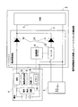
図1は、本発明の一実施形態に係る電池制御装置1を搭載したノートパソコン2(本発
明でいう、「電子機器」に相当。)の構成図を示している。ノートパソコン2内には、CPU(中央演算処理装置)やハードディスク等の装置類(以下、単に「負荷3」と称する。)が内蔵されている。負荷3は、ノートパソコン2に接続されている電池4やACアダプター5(本発明でいう、「電源装置」に相当。)から供給される電力によって動作する。なお、負荷3に供給される電力は、電池制御装置1を介して電池4やACアダプター5
から給電される。また、ACアダプター5の出力電圧は、電池4の出力電圧よりも高いことを前提としている。
<Configuration>
FIG. 1 shows a configuration diagram of a notebook personal computer 2 (corresponding to “electronic device” in the present invention) equipped with a battery control device 1 according to an embodiment of the present invention. The notebook
Power is supplied from Further, it is assumed that the output voltage of the
なお、本実施形態においては、電池4以外の電源としてACアダプター5を採用しているが、本発明はこれに限られない。すなわち、電池4からの電力の供給が無い状態であっても、電池制御装置1が動作可能であればよい。従って、ACアダプター5に代わって第二の電池を用いてもよいし、第二の電池以外の電源で電池制御装置1が動作するようにしてもよい。
In the present embodiment, the
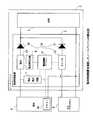
電池制御装置1は、電池4から負荷3への電力の供給を制御するための開閉装置6(本発明でいう、「電力路制御手段」に相当。)、電池4の電圧を計測する電圧測定回路7(本発明でいう、「電圧計測手段」に相当。)と、電池の電流を計測する電流測定回路8(本発明でいう、「電流計測手段」に相当。)と、開閉装置6へ制御信号を出力し、電圧測定回路7と電流測定回路8とからの計測信号を入力する電源制御マイコン9(本発明でいう、「電源制御手段」や「電源制御装置」に相当。)と、を有している。なお、電池制御装置1は、電池4の内部に設けられたメモリー14と電気的に接続されていてもよい。
The battery control device 1 is a switching device 6 (corresponding to “power path control means” in the present invention) for controlling power supply from the battery 4 to the
開閉装置6は、電池4への逆電流を阻止するためのダイオード10(本発明でいう、「第一のダイオード」に相当。)と、ACアダプター5への逆電流を阻止するためのダイオード11(本発明でいう、「第二のダイオード」に相当。)と、ACアダプター5と負荷3を繋ぐ電路を開閉するスイッチ12と、を有している。スイッチ12は、電源制御マイコン9からの指令を受けて開閉動作する。スイッチ12を開くと、電池4から負荷3へ電力が供給される。一方、スイッチ12を閉じると、ACアダプター5の出力電圧は電池4の出力電圧よりも高いため、電池4から負荷3への電力の供給は止まり、ACアダプター5から負荷3への電力の供給が開始される。すなわち、スイッチ12を開閉することにより、電池4から負荷3への電力の供給が制御される。なお、スイッチ12には、電路を物理的に開閉する電磁接触器等の開閉手段の他、半導体スイッチ等を用いてもよい。このように、ダイオード10とダイオード11とスイッチ12とからなる回路で電源の切り替え回路を構成することにより、負荷3を瞬時電圧低下させることなく電源を切り替えることが可能となる。また、電池4の内部インピーダンスや容量等を計測する際、ACアダプター5を取り外す必要が無くなる。なお、スイッチ12は、電池4から負荷3への電路の途中に設けてもよい。
The
電圧測定回路7は、電池4の正極と負極との間の電位差を計測し、電池4の出力電圧に関する信号を電源制御マイコン9に伝送する。なお、電圧測定回路7は、スイッチ12の開閉状態に関わらず、電池4の出力電圧を常に計測して電源制御マイコン9に伝送することが可能である。
The
電流測定回路8は、電池4の出力電流を計測し、電池4の出力電流に関する信号を電源制御マイコン9に伝送する。電池4の出力電流の計測は、電池4と負荷3との間に設けられた抵抗13における電圧降下量を計測し、電圧降下量と抵抗値とから電池4の出力電流を計測する。なお、スイッチ12が閉じており電池4から負荷3への電力の供給が停止している場合、電流測定回路8が計測する電池4の出力電流が0(A)になることは言うまでもない。
The
電源制御マイコン9は、開閉装置6のスイッチ12を開閉し、電池4から負荷3への電力の供給を制御したり、電圧測定回路7や電流測定回路8から伝送される信号に基づいて電池4の状態を測定する。電源制御マイコン9は、CPU(中央演算処理装置)、ROMやRAMで構成されるメモリー媒体、入出力インターフェース等により構成されており、メモリー媒体に予め格納されているプログラムが実行されることにより、電池制御装置1
の各動作が実現される。
The power
Each operation is realized.
<制御フロー>
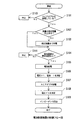
次に、本実施形態に係る電池制御装置1の動作について説明する。図2は、本実施形態に係る電池制御装置1の制御フロー図である。以下、図2に係るフロー図を参照しながら、電池制御装置1の各動作を説明する。
<Control flow>
Next, operation | movement of the battery control apparatus 1 which concerns on this embodiment is demonstrated. FIG. 2 is a control flow diagram of the battery control device 1 according to the present embodiment. Hereafter, each operation | movement of the battery control apparatus 1 is demonstrated, referring the flowchart which concerns on FIG.
ノートパソコン2の電源スイッチが押されて電池制御装置1が起動すると、電源制御マイコン9は、ノートパソコン2にACアダプター5が装着されているか否かを確認する(S101)。
When the battery control device 1 is activated by pressing the power switch of the
ACアダプター5が接続されていない場合、スイッチ12を閉じてもACアダプター5から負荷3へ電力が供給されない。よって、スイッチ12を開閉しても電池4から負荷3への電力の供給を停止することができない。電池4から負荷3への電力の供給を停止することができないと、電池4の開放電圧を測定することができないため、内部インピーダンスの測定をすることが不可能になる。よって、ACアダプター5が接続されていない場合は、電池4の状態測定を中止する(S110)。
When the
ACアダプター5が接続されている場合、スイッチ12を閉じることにより、電池4から負荷3への電力の供給を遮断することが可能となる。このため、電池4の開放電圧を測定することが可能になる。電池4の開放電圧を測定することが可能になると、負荷時の電池4の出力電圧および出力電流とに基づき、電池4の内部インピーダンスを計測することが可能になる。よって、ACアダプター5が接続されている場合は、次のステップ(S102)に移行する。
When the
電源制御マイコン9は、電池4の残量が規定残量(例えば、ACアダプター5から負荷3への電力の供給を遮断している間、負荷3が動作可能な電池残量。)を有している否かを確認する(S102)。
In the power
電池4の残量が規定残量よりも少ない場合、スイッチ12を開いている間に負荷3の電力消費によって電池4の残量がいずれ喪失してしまう。これにより、ノートパソコン2が予期せずにシャットダウンしてしまうのを防ぐため、電池4の残量が規定残量を満たすまで電池4を充電する(S103)。
If the remaining amount of the battery 4 is less than the specified remaining amount, the remaining amount of the battery 4 will eventually be lost due to the power consumption of the
電池4の残量が規定残量よりも多い場合、スイッチ12を開いていても負荷3の電力消費によって電池4の残量が喪失してしまうことはないため、次のステップ(S104)に移行する。
When the remaining amount of the battery 4 is greater than the specified remaining amount, the remaining amount of the battery 4 is not lost due to the power consumption of the
電源制御マイコン9は、電池4の温度が規定温度(本発明でいう、「所定の温度」に相当し、例えば、電池4の容量が設計値を満たす温度。)を有しているか否かを確認する(S104)。
The power
電池4の温度が規定温度よりも低い場合、電池4の容量が変化する。よって、適正な温度を逸脱した状態の電池4では、電池4の容量等を精度よく測定することができないので、電池4の状態測定を中止する(S111)。 When the temperature of the battery 4 is lower than the specified temperature, the capacity of the battery 4 changes. Therefore, in the battery 4 in a state of deviating from an appropriate temperature, the capacity of the battery 4 cannot be measured with high accuracy, so the state measurement of the battery 4 is stopped (S111).
電池4の温度が規定温度よりも高い場合、電池4は適正な状態(例えば、容量が設計値を満たす状態。)なので、次のステップ(S105)に移行する。なお、ノートパソコン2の使用環境が、電池4の温度が規定温度を逸脱し得ないような環境であれば、S104やS111を省略してもよい。
When the temperature of the battery 4 is higher than the specified temperature, the battery 4 is in an appropriate state (for example, a state where the capacity satisfies the design value), and the process proceeds to the next step (S105). Note that if the environment in which the
電源制御マイコン9は、スイッチ12を開き、負荷3への電力の供給元をACアダプタ
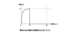
ー5から電池4へ切り替える(S105)。負荷3への電力の供給元をACアダプター5から電池4へ切り替えた時の時間を0分とする。このときの電池4の電圧と電流の変化を、図3、及び図4において示す。図3は、電池4の出力電圧の時間変化を示すグラフである。図3において示すように、電池4の出力電圧は、負荷3への給電の開始と同時に急速に低下し、時間が10分程度経過したところで収束する。また、図4は、電池4の出力電流の時間変化を示すグラフである。図4において示すように、電池4の出力電流は、負荷3への給電の開始と同時に急速に上昇し、時間が10(min)程度経過したところで収束する。
The power
電源制御マイコン9は、S105から10分経過後、電圧測定回路7から電池4の出力電圧(V1)(本発明でいう、「第一電圧」に相当。)に関する信号を取得し、電流測定回路8から電池4の出力電流(I1)(本発明でいう、「第一電流」に相当。)に関する信号を取得する(S106)。電源制御マイコン9は、電池4の出力電圧(V1)と出力電流(I1)とを取得したのち、次のステップ(S107)に移行する。
After 10 minutes from S105, the power
電源制御マイコン9は、スイッチ12を閉じ、負荷3への電力の供給元を電池4からACアダプター5へ切り替える(S107)。図3において示すように、電池4の出力電圧は、負荷3への給電の停止と同時に急速に上昇し、30分経過後にはほぼ完全に収束している。また、図4において示すように、電池4の出力電流は、負荷3への給電の停止と同時に0(A)となる。
The power
電源制御マイコン9は、S107から20分経過後(すなわち、S105から30分経過後。)、電圧測定回路7から電池4の開放電圧である出力電圧(V2)(本発明でいう、「第二電圧」に相当。)に関する信号を取得する(S108)。電源制御マイコン9は、電池4の出力電圧(V2)を取得したのち、次のステップ(S109)に移行する。
After 20 minutes from S107 (that is, after 30 minutes from S105), the power
電源制御マイコン9は、取得したV1、I1、及びV2から、電池4の内部インピーダンスZ(Ω)を算出する(S109)。内部インピーダンスZは、数式“Z=(V2−V1)÷I1”によって算出される。
The power
<効果>
以上により、本実施形態に係る電池制御装置1によれば、電池4から負荷3への電力の供給を制御する開閉装置6を備えているため、容易に電池4の内部インピーダンスを算出することが可能になる。
<Effect>
As described above, according to the battery control device 1 according to the present embodiment, since the
なお、電源制御マイコン9は、内部インピーダンスを所定の期間毎に定期的に算出してもよい。電池4の内部インピーダンスは電池の経年劣化によって徐々に変化するが、定期的に内部インピーダンスを算出し直すことで、正確な内部インピーダンスを把握することが可能である。ここで、所定の期間毎とは、内部インピーダンスを算出してから次に内部インピーダンスを算出するまでの間の電池4の充放電の積算時間であり、例えば、電池4の充放電を繰り返しても内部インピーダンスの変化量が無視できる時間数である。
The power
また、電源制御マイコン9は、内部インピーダンスを電池4の充電が完了した状態において算出するようにしてもよい。電池4の充電が完了するたびに内部インピーダンスを算出するようにすれば、電池の残量等が精度よく算出することが可能になる。
Further, the power
また、本実施形態において、電源制御マイコン9は、V1とI1を測定したのちにV2を測定している。しかし、本発明はこれに限られない。すなわち、電池4から負荷3への
給電を開始する前にV2を測定しておき、次に電池4から負荷3へ給電した状態でV1とI1とを測定するようにしてもよい。
In this embodiment, the power
<変形例1>
また、上述した実施形態において、電源制御マイコン9は、電池4の内部インピーダンスを算出している。しかし、本発明はこれに限られない。すなわち、以下のように変形することにより、電池4から負荷3へ電力を供給したままの状態で電池4の開放電圧を更に算出するようにしてもよい。
<Modification 1>
In the above-described embodiment, the power
詳細には、電源制御マイコン9は、電池4から負荷3へ電力を供給したままの状態で、電池4の出力電圧V3(本発明でいう、「第三電圧」に相当。)と電池4の出力電流I2(本発明でいう、「第二電流」に相当。)とを計測する。
Specifically, the power
次に、電源制御マイコン9は、既に算出してあるZと、新たに計測して取得したV3、及びI2から、電池4の開放電圧VO(V)を算出する。電池4の開放電圧VOは、数式“VO=V3+Z×I2”によって算出される。
Next, the power
以上により、本変形例に係る電池制御装置1によれば、電池4が負荷3へ電力を供給している状態においても、容易に電池4の開放電圧を測定することが可能になる。
As described above, according to the battery control device 1 according to this modification, it is possible to easily measure the open-circuit voltage of the battery 4 even when the battery 4 supplies power to the
<変形例2>
上述した変形例1において、電源制御マイコン9は、電池4の開放電圧を算出している。しかし、本発明はこれに限られない。すなわち、以下のように変形することにより、電池4の残量が全容量に占める割合を表した値である電池残量比率を更に取得するようにしてもよい。
<
In the first modification described above, the power
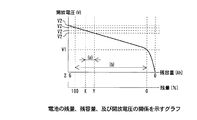
図5は、電池4の残量比率(%)と開放電圧(V)との関係を示すグラフ(本発明でいう、「マップ」に相当。)である。この電池4の残量比率(%)と開放電圧(V)との関係は、電池4の製造時等において、計測装置によって予め計測されたデータに基づくものである。すなわち、このマップは、電池4の開放電圧を電池4が満充電の状態から放電末期の状態になるまで段階的に計測していくことにより作成したものである。電池4のメモリー14にこのようなグラフをマップとして予め記憶させておき、電池4を電池制御装置1に接続させた際に電源制御マイコン9にマップを読み込ませ、上述した変形例1において算出した電池4の開放電圧とマップとを照合させることで、電池4の残量が算出される。
FIG. 5 is a graph (corresponding to “map” in the present invention) showing the relationship between the remaining amount ratio (%) of the battery 4 and the open circuit voltage (V). The relationship between the remaining amount ratio (%) of the battery 4 and the open circuit voltage (V) is based on data measured in advance by a measuring device when the battery 4 is manufactured. In other words, this map is created by measuring the open circuit voltage of the battery 4 stepwise from the fully charged state to the end-of-discharge state. Such a graph is stored in advance in the
以上により、本変形例に係る電池制御装置1によれば、電池4が負荷3へ電力を供給している状態でも容易に電池4の残量を測定することが可能になる。
As described above, according to the battery control device 1 according to the present modification, it is possible to easily measure the remaining amount of the battery 4 even when the battery 4 supplies power to the
<変形例3>
上述した電池制御装置1は、以下のように変形することで、電池4の満充電容量を更に算出するようにしてもよい。すなわち、上述した実施形態に係る電源制御マイコン9の制御フローを以下のように変形する。
<
The battery control apparatus 1 described above may be further modified as follows to further calculate the full charge capacity of the battery 4. That is, the control flow of the power
<変形例3の制御フロー>
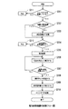
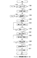
図6は、本変形例に係る電池制御装置1の制御フロー図である。以下、図6に示すフロー図を参照しながら、本変形例に係る電池制御装置1の各動作を説明する。
<Control Flow of
FIG. 6 is a control flow diagram of the battery control device 1 according to this modification. Hereafter, each operation | movement of the battery control apparatus 1 which concerns on this modification is demonstrated, referring the flowchart shown in FIG.
図6に示すフロー図において、S201〜S205、S211、及びS212に示すステップは、上述した実施形態におけるS101〜S105、S110、及びS111と同
様なので、その説明を省略する。なお、ノートパソコン2の使用環境が、電池4の温度が規定温度を逸脱し得ないような環境であれば、S204やS212を省略してもよい。
In the flowchart shown in FIG. 6, the steps shown in S201 to S205, S211 and S212 are the same as S101 to S105, S110 and S111 in the above-described embodiment, and the description thereof will be omitted. Note that if the environment in which the
電源制御マイコン9は、S205において負荷3への電力の供給元をACアダプター5から電池4へ切り替えた後、電池4の出力電流に関する信号を取得し、出力電流の積算を開始する(S206)。
The power
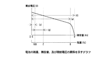
図7は、電池4の残量が全容量に占める割合を表した値である電池残量比率(%)、残容量(Ah)、及び開放電圧(V)の関係を示すグラフである。電源制御マイコン9は、電池4の開放電圧とマップとから電池4の残量比率を取得する。また、電源制御マイコン9は、図7のグラフにおいて電池4が任意の残量比率X(%)(本発明でいう、「第一電池残量比率」に相当。)の状態(本発明でいう、「第一電池状態」に相当。)になった時に、電池4の出力電流の積算を開始(S206)したものとする。
FIG. 7 is a graph showing the relationship between the remaining battery ratio (%), the remaining capacity (Ah), and the open circuit voltage (V), which are values representing the ratio of the remaining capacity of the battery 4 to the total capacity. The power
電源制御マイコン9は、S206において電池4の出力電流の積算を開始したのち、電池4の残量が規定の残量比率Y(%)になるまで、出力電流の積算を継続する(S207)。電源制御マイコン9は、電池4が残量比率X(%)よりも残量の少ない規定の残量比率Y(%)(本発明でいう、「第二電池残量」に相当。)の状態(本発明でいう、「第二電池状態」に相当。)になったら出力電流の積算を中止し、出力電流の積算値(図7における(a)に相当。)(本発明でいう、「第一積算電流」に相当。)を記憶する(S208)。電源制御マイコン9は、電池4の出力電流の積算値を取得したのち、次のステップ(S209)に移行する。
After starting the integration of the output current of the battery 4 in S206, the power
電源制御マイコン9は、取得した積算値、残量比率X、及び残量比率Yから電池4の満充電容量(図7における(b)に相当。)を算出する(S209)。電池4の満充電容量は、数式“満充電容量=積算値×100÷(残量比率X−残量比率Y)”によって算出される。電源制御マイコン9は、電池4の満充電容量を算出したのち、次のステップ(S210)に移行する。
The power
電源制御マイコン9は、電池4の残量の低下を抑制するため、スイッチ12を閉じ、負荷3への電力の供給元を電池4からACアダプター5へ切り替える。
The power
<変形例3の効果>
以上により、本変形例に係る電池制御装置1によれば、電池4が負荷3へ電力を供給している状態でも電池4の満充電容量を測定することが可能になる。
<Effect of
As described above, according to the battery control device 1 according to the present modification, it is possible to measure the full charge capacity of the battery 4 even when the battery 4 supplies power to the
なお、満充電容量の測定は、内部インピーダンスを算出してから所定の期間内に行うようにしてもよい。内部インピーダンスを算出してから満充電容量を測定するまでの間の時間が長すぎると、電池の経年劣化によって内部インピーダンスが変化してしまい、正確な満充電容量が算出できなくなるためである。ここで、所定の期間とは、電池4の積算使用時間であり、例えば、電池4の充放電を繰り返しても内部インピーダンスの変化量が無視できる時間数である。 The full charge capacity may be measured within a predetermined period after calculating the internal impedance. This is because if the time between the calculation of the internal impedance and the measurement of the full charge capacity is too long, the internal impedance changes due to the aging of the battery, and an accurate full charge capacity cannot be calculated. Here, the predetermined period is the accumulated usage time of the battery 4, for example, the number of hours in which the change amount of the internal impedance can be ignored even when the battery 4 is repeatedly charged and discharged.
また、満充電容量の測定は、所定の期間毎に繰り返し行うようにしてもよい。電池4の満充電容量は、電池4の経年劣化等によって変化する。従って、満充電容量の測定間隔があまりにも長いと、算出される電池残量比率が実際の電池残量比率と大きく相違してしまう場合がある。電池4の満充電容量の測定を定期的に繰り返すことで、正確な満充電容量を把握することが可能になる。 Further, the measurement of the full charge capacity may be repeated every predetermined period. The full charge capacity of the battery 4 changes due to aging of the battery 4 or the like. Therefore, if the measurement interval of the full charge capacity is too long, the calculated battery remaining capacity ratio may greatly differ from the actual battery remaining capacity ratio. By repeating the measurement of the full charge capacity of the battery 4 periodically, it becomes possible to grasp the exact full charge capacity.
<変形例4>
上述した電池制御装置1は、以下のように変形することで、電池4の満充電容量を更に補正するようにしてもよい。すなわち、上述した実施形態に係る電源制御マイコン9の制御フローを以下のように変形する。
<Modification 4>
The battery control device 1 described above may be further modified as follows to further correct the full charge capacity of the battery 4. That is, the control flow of the power
<変形例4の制御フロー>
図8は、本変形例に係る電池制御装置1の制御フロー図である。以下、図8に示すフロー図を参照しながら、本変形例に係る電池制御装置1の各動作を説明する。
<Control Flow of Modification 4>
FIG. 8 is a control flow diagram of the battery control device 1 according to this modification. Hereafter, each operation | movement of the battery control apparatus 1 which concerns on this modification is demonstrated, referring the flowchart shown in FIG.
図8に示すフロー図において、S301、及びS312に示すステップは上述した実施形態におけるS101、及びS110と同様であり、S303、S304、及びS313は上述した実施形態におけるS104、S105、及びS111と同様であるため、その説明を省略する。なお、ノートパソコン2の使用環境が、電池4の温度が規定温度を逸脱し得ないような環境であれば、S303やS313を省略してもよい。
In the flowchart shown in FIG. 8, the steps shown in S301 and S312 are the same as S101 and S110 in the above-described embodiment, and S303, S304, and S313 are the same as S104, S105, and S111 in the above-described embodiment. Therefore, the description thereof is omitted. Note that if the use environment of the
電源制御マイコン9は、S301においてノートパソコン2にACアダプター5が接続されていることを確認したら、次のステップ(S302)に移行する。
After confirming that the
電源制御マイコン9は、S302において電池4を満充電まで充電する。電池4が満充電状態に達したのち、次のステップ(S303)に移行する。
The power
電源制御マイコン9は、S303において電池4の温度が規定温度以上であることを確認したのち、負荷3への電力の供給元をACアダプター5から電池4へ切り替える(S304)。そして、負荷3への電力の供給元をACアダプター5から電池4へ切り替えた後、電池4の出力電流に関する信号を取得し、出力電流の積算を開始する(S305)。
After confirming that the temperature of the battery 4 is equal to or higher than the specified temperature in S303, the power
図9は、電池4の残量比率(%)、残容量(Ah)、及び開放電圧(V)の関係を示すグラフである。電源制御マイコン9は、図9のグラフにおいて、電池4が満充電の状態(すなわち、図9における残容量2.6(Ah)に相当。)から、電池4の出力電流の積算を開始(S305)したものとする。
FIG. 9 is a graph showing the relationship between the remaining capacity ratio (%), remaining capacity (Ah), and open circuit voltage (V) of the battery 4. In the graph of FIG. 9, the power
電源制御マイコン9は、S305において電池4の出力電流の積算を開始したのち、電池4の残量比率が100(%)になるまで、出力電流の積算を継続する(S306)。電源制御マイコン9は、電池4が残量100(%)の状態になったら出力電流の積算を中断し、出力電流の積算値(図9における(c)に相当。)(本発明でいう、「第二積算電流」に相当。)を記憶する(S307)。電源制御マイコン9は、電池4の出力電流の積算値を取得したのち、次のステップ(S308)に移行する。
After starting the integration of the output current of the battery 4 in S305, the power
電源制御マイコン9は、S308において電池4の出力電流の積算を再開したのち、電池4の残量比率が規定の残量比率Z(%)になるまで、出力電流の積算を継続する(S309)。電源制御マイコン9は、電池4が残量100(%)よりも残量の少ない規定の残量比率Z(%)の状態になったら出力電流の積算を中止し、出力電流の積算値(図9における(d)に相当。)を記憶する。電源制御マイコン9は、電池4の出力電流の積算値(d)を取得したのち、次のステップ(S310)に移行する。
After restarting the integration of the output current of the battery 4 in S308, the power
電源制御マイコン9は、取得した積算値(c)、積算値(d)、及び残量比率Zから電池4の満充電容量(図9における(e)に相当。)を算出する(S310)。電池4の満充電容量は、数式"満充電容量(e)=(積算値(c)+積算値(d)×100÷(100−残量比率Z))"によって算出される。電源制御マイコン9は、電池4の満充電容量(e)を算出したのち、次のステップ(S311)に移行する。
The power
電源制御マイコン9は、電池4の残量の低下を抑制するため、スイッチ12を閉じ、負荷3への電力の供給元を電池4からACアダプター5へ切り替える(S311)。
The power
<変形例4の効果>
以上により、本変形例に係る電池制御装置1によれば、電池4の満充電容量を補正して精度を高めることが可能になる。
<Effect of Modification 4>
As described above, according to the battery control device 1 according to the present modification, it is possible to improve the accuracy by correcting the full charge capacity of the battery 4.
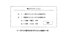
なお、本変形例に係る満充電容量の補正は、ユーザからの要求に応じて行うようにしてもよい。図10において、ユーザからの要求を受け付ける入力画面の一例を示す。入力画面上にあるチェックボックスをチェックし、設定ボタンを押すことで、ユーザからの要求が電源制御マイコン9に伝達される。
In addition, you may make it correct | amend the full charge capacity | capacitance which concerns on this modification according to the request | requirement from a user. FIG. 10 shows an example of an input screen that receives a request from the user. When a check box on the input screen is checked and a setting button is pressed, a request from the user is transmitted to the power
また、ユーザから満充電容量の補正に関する要求が無かった場合には、満充電容量を算出してから所定の期間が経過したのちに満充電容量の補正を行うようにしてもよい。ここで、所定の期間とは、電池4の積算使用時間であり、例えば、電池4の充放電を繰り返しても満充電容量の変化量が無視できる時間数である。 Further, when there is no request for correction of the full charge capacity from the user, the full charge capacity may be corrected after a predetermined period has elapsed since the full charge capacity was calculated. Here, the predetermined period is the accumulated usage time of the battery 4, for example, the number of hours in which the amount of change in the full charge capacity can be ignored even when the battery 4 is repeatedly charged and discharged.
<変形例5>
上述した変形例4において、電源制御マイコン9は、電池4の電池4の残量比率100%よりも上の容量を加算することで電池4の満充電容量を補正している。しかし、本発明はこれに限られない。すなわち、以下のように変形することにより、電池4の満充電容量を更に補正するようにしてもよい。
<
In the fourth modification described above, the power
上述した変形例4のS310において、算出した満充電容量(e)に更に補正係数αを乗
算する。補正係数αは、電池4が残量0%の状態から過放電の状態に移行するまでの間に出力する電流の積算値が全体の容量に占める割合に1を加算した値であり、例えば、補正係数α=1.02とする。
In S310 of Modification 4 described above, the calculated full charge capacity (e) is further multiplied by a correction coefficient α. The correction coefficient α is a value obtained by adding 1 to the ratio of the integrated value of the current output before the battery 4 shifts from the 0% remaining state to the overdischarged state in the total capacity. The correction coefficient α = 1.02.
以上により、本変形例に係る電池制御装置1によれば、電池4の満充電容量を補正して精度を高めることが可能になる。 As described above, according to the battery control device 1 according to the present modification, it is possible to improve the accuracy by correcting the full charge capacity of the battery 4.
なお、本変形例に係る満充電容量の補正は、上述した変形例4と同様、ユーザからの要求に応じて行うようにしたり、ユーザからの要求が無い場合には所定の期間ごとに行うようにしてもよい。 In addition, the correction of the full charge capacity according to the present modification is performed in response to a request from the user as in the above-described modification 4, or is performed every predetermined period when there is no request from the user. It may be.
<変形例6>
上述した電池制御装置1は、電池4内に設けられたメモリー14に、算出した満充電容量を更に記憶させるように変形してもよい。これによれば、電池4が交換されるたびに満充電容量を測定し直す必要がなくなる。
<
The battery control device 1 described above may be modified to further store the calculated full charge capacity in the
<変形例7>
上述した電池制御装置1は、内部に電圧測定回路7と電流測定回路8とを備えているが、本発明はこのような構成に限られない。図11において、本変形例に係る電池制御装置1を搭載したノートパソコン2の構成図を示す。図11において示すように、電池4(バッテリーパック)の内部に制御IC15と電圧測定回路7と電流測定回路8とを配設し、電圧測定回路7によって計測される電圧信号と電流測定回路8によって計測される電流信号とを制御IC15を介して電源制御マイコン9に転送するようにしてもよい。
<
The battery control device 1 described above includes the
また、本発明の電池制御装置、電池制御方法、電源制御装置、及び電子機器は、以下のような付記的事項を含むものである。 The battery control device, battery control method, power supply control device, and electronic device of the present invention include the following additional items.
〔その他〕
本発明は、以下のように特定することができる。
(付記1)電池から負荷への電力の供給を制御する電力路制御手段と、前記電池の電圧を計測する電圧計測手段と、前記電池の電流を計測する電流計測手段と、前記電力路制御手段へ制御信号を出力し、前記電圧計測手段と前記電流計測手段とからの計測信号を入力する電源制御手段と、を備え、前記電源制御手段は、前記電池から前記負荷へ電力を供給した状態において、該電池の電圧である第一電圧と該電池の電流である第一電流とを計測し、前記電池から前記負荷への電力の供給を遮断した状態において、該電池の電圧である第二電圧を計測し、前記第二電圧を前記第一電圧で減算した値を前記第一電流で除算し、前記電池の内部インピーダンスを算出する、電池制御装置。(1)
(付記2)前記電力路制御手段は、前記電池から前記負荷への電力の供給回路上に配設された第一のダイオードと、該電池よりも電圧の高い電源装置から前記負荷への電力の供給回路上に配設された第二のダイオードと、前記電源装置から前記第二のダイオードへの電力の供給回路上に配設されたスイッチと、を有し、前記スイッチを開くと、前記電源装置から前記負荷への電力の供給が遮断されて前記電池から前記負荷へ電力が供給され、前記スイッチを閉じると、前記電源装置から前記負荷へ電力が供給されて前記電池から前記負荷への電力の供給が遮断される、付記1に記載の電池制御装置。
(付記3)前記電源制御手段は、前記電池から前記負荷へ電力を供給した状態において、前記電池の電圧である第三電圧と該電池の電流である第二電流とを更に計測し、前記内部インピーダンスに前記第二電流を乗算した値に前記第三電圧を加算し、前記電池の開放電圧を更に算出する、付記1又は2に記載の電池制御装置。(2)
(付記4)前記電池制御装置は、予め作成した前記電池の残量が全容量に占める割合を表した値である電池残量比率と前記開放電圧との関係を示すマップを更に備え、前記電源制御手段は、前記マップと前記開放電圧とを照合し、前記電池の電池残量比率を更に取得する、付記3に記載の電池制御装置。(3)
(付記5)前記電源制御手段は、残量が低下する前の前記電池の状態である第一電池状態において該電池の開放電圧を算出し、前記マップと該開放電圧とを照合して該電池の残量が全容量に占める割合を表した値である第一電池残量比率を更に計測し、残量が低下した後の前記電池の状態である第二電池状態において該電池の開放電圧を算出し、前記マップと該開放電圧とを照合して該電池の残量が全容量に占める割合を表した値である第二電池残量比率を更に計測し、前記電池が前記第一電池状態から前記第二電池状態に変化するまでの間に出力した電流の積算値である第一積算電流を更に計測し、前記第一積算電流を前記第一電池残量比率から前記第二電池残量比率を減算した値で除算し、前記電池の満充電容量を更に算出する、付記4に記載の電池制御装置。(4)
(付記6)前記電源制御手段は、前記電池の残量が満充電の状態から100%の状態に移行するまでの間に出力した電流の積算値である第二積算電流を更に計測し、前記満充電容量に前記第二積算電流を加算し、前記電池の満充電容量を更に補正する、付記5に記載の電池制御装置。
(付記7)前記電源制御手段は、前記満充電容量に、前記電池の残量が0%の状態から過放電の状態に至るまでの容量が全容量に対して占める割合を乗算し、該満充電容量を更に補正する、付記5又は6に記載の電池制御装置。
(付記8)前記電池制御装置は、前記電池の温度を計測する温度検出手段を更に備え、前記電源制御手段は、前記電池の温度が所定の温度以上の場合に前記満充電容量を更に算出する、付記5に記載の電池制御装置。
(付記9)前記第一電池状態は、前記電池から前記負荷への電力の供給が開始される前の状態であり、前記第二電池状態は、前記電池から前記負荷への電力の供給が停止された後の状態である、付記5に記載の電池制御装置。
(付記10)前記マップに示された前記電池残量比率と前記開放電圧との関係は、前記電池の製造時に計測装置によって予め計測されたデータに示されたものである、付記4から
9の何れかに記載の電池制御装置。
(付記11)電池から負荷への電力の供給を制御する電力路制御手段と、前記電池の電圧を計測する電圧計測手段と、前記電池の電流を計測する電流計測手段と、前記電力路制御手段へ制御信号を出力し、前記電圧計測手段と前記電流計測手段とからの計測信号を入力する電源制御手段と、を備える電池制御装置の電池制御方法であって、前記電源制御手段は、前記電池から前記負荷へ電力を供給した状態において、該電池の電圧である第一電圧と該電池の電流である第一電流とを計測し、前記電池から前記負荷への電力の供給を遮断した状態において、該電池の電圧である第二電圧を計測し、前記第二電圧を前記第一電圧で減算した値を前記第一電流で除算し、前記電池の内部インピーダンスを算出する、電池制御方法。(5)
(付記12)前記電力路制御手段は、前記電池から前記負荷への電力の供給回路上に配設された第一のダイオードと、前記電池よりも電圧の高い電源装置から前記負荷への電力の供給回路上に配設された第二のダイオードと、前記電源装置から前記第二のダイオードへの電力の供給回路上に配設されたスイッチと、を有し、前記スイッチを開くと、前記電源装置から前記負荷への電力の供給が遮断されて前記電池から前記負荷へ電力が供給され、前記スイッチを閉じると、前記電源装置から前記負荷へ電力が供給されて前記電池から前記負荷への電力の供給が遮断される、付記11に記載の電池制御方法。
(付記13)前記電源制御手段は、前記電池から前記負荷へ電力を供給した状態において、該電池の電圧である第三電圧と該電池の電流である第二電流とを更に計測し、前記内部インピーダンスに前記第二電流を乗算した値に前記第三電圧を加算し、前記電池の開放電圧を更に算出する、付記11又は12に記載の電池制御方法。(6)
(付記14)前記電池制御装置は、予め作成した前記電池の残量が全容量に占める割合を表した値である電池残量比率と前記開放電圧との関係を示すマップを更に備え、前記電源制御手段は、前記マップと前記開放電圧とを照合し、前記電池の電池残量比率を更に取得する、付記13に記載の電池制御方法。(7)
(付記15)前記電源制御手段は、残量が低下する前の前記電池の状態である第一電池状態において該電池の開放電圧を算出し、前記マップと該開放電圧とを照合して該電池の残量が全容量に占める割合を表した値である第一電池残量比率を更に計測し、残量が低下した後の前記電池の状態である第二電池状態において該電池の開放電圧を算出し、前記マップと該開放電圧とを照合して該電池の残量が全容量に占める割合を表した値である第二電池残量比率を更に計測し、前記電池が前記第一電池状態から前記第二電池状態に変化するまでの間に出力した電流の積算値である第一積算電流を更に計測し、前記第一積算電流を前記第一電池残量比率から前記第二電池残量比率を減算した値で除算し、前記電池の満充電容量を更に算出する、付記14に記載の電池制御方法。(8)
(付記16)前記電源制御手段は、前記電池の残量が満充電の状態から100%の状態に移行するまでの間に出力した電流の積算値である第二積算電流を更に計測し、前記満充電容量に前記第二積算電流を加算し、前記電池の満充電容量を更に補正する、付記15に記載の電池制御方法。
(付記17)前記電源制御手段は、前記満充電容量に、前記電池の残量が0%の状態から過放電の状態に至るまでの容量が全容量に対して占める割合を乗算し、該満充電容量を更に補正する、付記15又は16に記載の電池制御方法。
(付記18)前記電池制御装置は、前記電池の温度を計測する温度検出手段を更に備え、前記電源制御手段は、前記電池の温度が所定の温度以上の場合に前記満充電容量を更に算出する、付記15に記載の電池制御方法。
(付記19)前記第一電池状態は、前記電池から前記負荷への電力の供給が開始される前の状態であり、前記第二電池状態は、前記電池から前記負荷への電力の供給が停止された後の状態である、付記15に記載の電池制御方法。
(付記20)前記マップに示された前記電池残量比率と前記開放電圧との関係は、前記電池の製造時に計測装置によって予め計測されたデータに基づくものである、付記14から19の何れかに記載の電池制御方法。
(付記21)電池から負荷への電力の供給を制御する電力路制御手段と、前記電池の電圧を計測する電圧計測手段と、前記電池の電流を計測する電流計測手段と、を備える電子機器に用いられる電源制御装置であって、前記電池から前記負荷へ電力を供給した状態において、該電池の電圧である第一電圧と該電池の電流である第一電流とを計測し、前記電池から前記負荷への電力の供給を遮断した状態において、該電池の電圧である第二電圧を計測し、前記第二電圧を前記第一電圧で減算した値を前記第一電流で除算し、前記電池の内部インピーダンスを算出する、電源制御装置。(9)
(付記22)電池を備え、電力によって駆動する電子機器であって、前記電池から前記電子機器内の負荷への電力の供給を制御する電力路制御手段と、前記電池の電圧を計測する電圧計測手段と、前記電池の電流を計測する電流計測手段と、前記電力路制御手段へ制御信号を出力し、前記電圧計測手段と前記電流計測手段とからの計測信号を入力する電源制御手段と、を備え、前記電源制御手段は、前記電池から前記負荷へ電力を供給した状態において、該電池の電圧である第一電圧と該電池の電流である第一電流とを計測し、前記電池から前記負荷への電力の供給を遮断した状態において、該電池の電圧である第二電圧を計測し、前記第二電圧を前記第一電圧で減算した値を前記第一電流で除算し、前記電池の内部インピーダンスを算出する、電子機器。(10)
(付記23)電池から負荷への電力の供給を制御する電力路制御手段と、前記電池の電圧を計測する電圧計測手段と、前記電池の電流を計測する電流計測手段と、前記電力路制御手段へ制御信号を出力し、前記電圧計測手段と前記電流計測手段とからの計測信号を入力する電源制御手段と、を備える電池制御装置の電池制御プログラムであって、前記電池から前記負荷へ電力を供給した状態において該電池の電圧である第一電圧と該電池の電流である第一電流とを計測する手順と、前記電池から前記負荷への電力の供給を遮断した状態において該電池の電圧である第二電圧を計測する手順と、前記第二電圧を前記第一電圧で減算した値を前記第一電流で除算し前記電池の内部インピーダンスを算出する手順と、を電池制御装置に実行させるための電池制御プログラム。
[Others]
The present invention can be specified as follows.
(Appendix 1) Power path control means for controlling the supply of power from the battery to the load, voltage measurement means for measuring the voltage of the battery, current measurement means for measuring the current of the battery, and the power path control means Power control means for outputting a control signal to and inputting measurement signals from the voltage measurement means and the current measurement means, wherein the power control means supplies power from the battery to the load. The first voltage that is the voltage of the battery and the first current that is the current of the battery are measured, and the second voltage that is the voltage of the battery in a state where the supply of power from the battery to the load is cut off. A battery control device that calculates the internal impedance of the battery by dividing a value obtained by subtracting the second voltage by the first voltage by the first current. (1)
(Supplementary Note 2) The power path control means includes: a first diode disposed on a power supply circuit from the battery to the load; and a power supply device having a voltage higher than that of the battery. A second diode disposed on a supply circuit; and a switch disposed on a power supply circuit from the power supply device to the second diode. When the switch is opened, the power supply When power supply from the device to the load is interrupted, power is supplied from the battery to the load, and when the switch is closed, power is supplied from the power supply device to the load and power from the battery to the load. The battery control device according to appendix 1, wherein the supply of is cut off.
(Supplementary Note 3) In the state where power is supplied from the battery to the load, the power supply control unit further measures a third voltage that is a voltage of the battery and a second current that is a current of the battery, The battery control device according to
(Additional remark 4) The said battery control apparatus is further provided with the map which shows the relationship between the battery residual ratio and the said open circuit voltage which are the values showing the ratio for which the residual amount of the said battery produced in the total capacity is comprised, The battery control apparatus according to
(Supplementary Note 5) The power supply control means calculates the open voltage of the battery in the first battery state, which is the state of the battery before the remaining amount is reduced, and compares the map with the open voltage to check the battery The remaining amount ratio of the first battery, which is a value representing the ratio of the remaining amount to the total capacity, is further measured, and the open-circuit voltage of the battery in the second battery state, which is the state of the battery after the remaining amount is reduced, is measured. Calculating and comparing the map with the open-circuit voltage to further measure a second battery remaining amount ratio, which is a value representing a ratio of the remaining amount of the battery to the total capacity, and the battery is in the first battery state The first integrated current, which is an integrated value of the current output during the period from when the battery is changed to the second battery state, is further measured, and the first integrated current is calculated from the first battery remaining amount ratio to the second battery remaining amount. (4) further dividing the full charge capacity of the battery by dividing the ratio by the subtracted value; Cell control system according. (4)
(Appendix 6) The power supply control means further measures a second integrated current that is an integrated value of the current output until the remaining amount of the battery shifts from a fully charged state to a 100% state, The battery control device according to
(Supplementary note 7) The power supply control unit multiplies the full charge capacity by a ratio of the capacity from the remaining battery level of 0% to the overdischarged state with respect to the total capacity. The battery control device according to
(Additional remark 8) The said battery control apparatus is further provided with the temperature detection means which measures the temperature of the said battery, and the said power supply control means further calculates the said full charge capacity when the temperature of the said battery is more than predetermined | prescribed temperature. The battery control device according to
(Supplementary Note 9) The first battery state is a state before the supply of power from the battery to the load is started, and the second battery state is the supply of power from the battery to the load is stopped. The battery control device according to
(Supplementary Note 10) The relationship between the battery remaining ratio and the open-circuit voltage shown in the map is shown in data preliminarily measured by a measuring device at the time of manufacturing the battery. The battery control apparatus in any one.
(Supplementary note 11) Power path control means for controlling the supply of power from the battery to the load, voltage measurement means for measuring the voltage of the battery, current measurement means for measuring the current of the battery, and the power path control means A battery control method for a battery control device comprising: a power supply control means for outputting a control signal to the power supply control means for inputting measurement signals from the voltage measurement means and the current measurement means, wherein the power supply control means comprises the battery In a state in which power is supplied from the battery to the load, the first voltage that is the voltage of the battery and the first current that is the current of the battery are measured, and the supply of power from the battery to the load is cut off. A battery control method of measuring a second voltage that is a voltage of the battery, dividing a value obtained by subtracting the second voltage by the first voltage by the first current, and calculating an internal impedance of the battery. (5)
(Supplementary Note 12) The power path control means includes: a first diode disposed on a power supply circuit from the battery to the load; and a power supply from the power supply device having a higher voltage than the battery to the load. A second diode disposed on a supply circuit; and a switch disposed on a power supply circuit from the power supply device to the second diode. When the switch is opened, the power supply When power supply from the device to the load is interrupted, power is supplied from the battery to the load, and when the switch is closed, power is supplied from the power supply device to the load and power from the battery to the load. The battery control method according to
(Supplementary Note 13) In the state where power is supplied from the battery to the load, the power supply control unit further measures a third voltage that is a voltage of the battery and a second current that is a current of the battery, and The battery control method according to
(Additional remark 14) The said battery control apparatus is further provided with the map which shows the relationship between the battery residual ratio and the said open circuit voltage which are the values showing the ratio for which the remaining amount of the said battery produced in the capacity | capacitance occupies, and the said
(Supplementary Note 15) The power supply control means calculates the open voltage of the battery in the first battery state that is the state of the battery before the remaining amount is reduced, and compares the map with the open voltage to check the battery The remaining amount ratio of the first battery, which is a value representing the ratio of the remaining amount of the battery to the total capacity, is further measured. Calculating and comparing the map with the open-circuit voltage to further measure a second battery remaining amount ratio, which is a value representing a ratio of the remaining amount of the battery to the total capacity, and the battery is in the first battery state The first integrated current, which is an integrated value of the current output during the period from when the battery is changed to the second battery state, is further measured, and the first integrated current is calculated from the first battery remaining amount ratio to the second battery remaining amount. Further dividing the ratio by the subtracted value to further calculate the full charge capacity of the battery. Battery control method according to 4. (8)
(Supplementary Note 16) The power supply control means further measures a second integrated current that is an integrated value of the current output until the remaining amount of the battery shifts from a fully charged state to a 100% state, The battery control method according to
(Supplementary Note 17) The power supply control means multiplies the full charge capacity by a ratio of the capacity from the remaining battery level of 0% to the overdischarged state with respect to the total capacity, The battery control method according to
(Additional remark 18) The said battery control apparatus is further provided with the temperature detection means to measure the temperature of the said battery, and the said power supply control means further calculates the said full charge capacity when the temperature of the said battery is more than predetermined temperature. The battery control method according to
(Supplementary Note 19) The first battery state is a state before the supply of power from the battery to the load is started, and the second battery state is a stop of supply of power from the battery to the load. The battery control method according to
(Supplementary note 20) Any one of
(Supplementary note 21) An electronic device comprising: a power path control unit that controls supply of power from a battery to a load; a voltage measurement unit that measures the voltage of the battery; and a current measurement unit that measures the current of the battery. A power supply control device used, in a state in which power is supplied from the battery to the load, the first voltage that is the voltage of the battery and the first current that is the current of the battery are measured, In a state where power supply to the load is cut off, a second voltage that is the voltage of the battery is measured, and a value obtained by subtracting the second voltage by the first voltage is divided by the first current, A power supply control device that calculates internal impedance. (9)
(Supplementary note 22) An electronic device including a battery and driven by electric power, the power path control means for controlling the supply of electric power from the battery to the load in the electronic device, and the voltage measurement for measuring the voltage of the battery Means, current measuring means for measuring the current of the battery, power supply control means for outputting a control signal to the power path control means and inputting measurement signals from the voltage measuring means and the current measuring means, The power control means measures a first voltage that is a voltage of the battery and a first current that is a current of the battery in a state in which power is supplied from the battery to the load, and the load from the battery In a state where power supply to the battery is cut off, a second voltage, which is the voltage of the battery, is measured, and a value obtained by subtracting the second voltage by the first voltage is divided by the first current, Calculate impedance , Electronic equipment. (10)
(Supplementary note 23) Power path control means for controlling the supply of power from the battery to the load, voltage measurement means for measuring the voltage of the battery, current measurement means for measuring the current of the battery, and the power path control means A battery control program for a battery control device comprising: a power supply control means for outputting a control signal to the power supply control means for inputting a measurement signal from the voltage measurement means and the current measurement means, wherein power is supplied from the battery to the load. A procedure for measuring a first voltage that is a voltage of the battery in a supplied state and a first current that is a current of the battery, and a voltage of the battery in a state where supply of power from the battery to the load is cut off. The battery control device executes a procedure for measuring a second voltage and a procedure for calculating the internal impedance of the battery by dividing a value obtained by subtracting the second voltage by the first voltage by the first current. Battery control program.
1・・・・・・・・・電池制御装置
2・・・・・・・・・ノートパソコン
3・・・・・・・・・負荷
4・・・・・・・・・電池
5・・・・・・・・・ACアダプター
6・・・・・・・・・開閉装置
7・・・・・・・・・電圧測定回路
8・・・・・・・・・電流測定回路
9・・・・・・・・・電源制御マイコン
10、11・・・・・ダイオード
12・・・・・・・・スイッチ
13・・・・・・・・抵抗
14・・・・・・・・メモリー
15・・・・・・・・制御IC
1 ...
Claims (14)
前記電池の電圧を計測する電圧計測手段と、
前記電池の電流を計測する電流計測手段と、
前記電力路制御手段へ制御信号を出力し、前記電圧計測手段と前記電流計測手段とからの計測信号を入力する電源制御手段と、を備え、
前記電力路制御手段は、前記電池よりも電圧の高い電源装置から前記負荷へ繋がる回路に設けたスイッチのオンオフによって、前記電池から前記負荷への電力の供給を制御し、
前記電源制御手段は、
前記電池から前記負荷へ電力を供給した状態において、該電池の電圧である第一電圧と該電池の電流である第一電流とを計測し、
前記電池から前記負荷への電力の供給を遮断した状態において、該電池の電圧である第二電圧を計測し、
前記第二電圧を前記第一電圧で減算した値を前記第一電流で除算し、前記電池の内部インピーダンスを算出し、
前記電池から前記負荷へ電力を供給した状態において、該電池の電圧である第三電圧と該電池の電流である第二電流とを、前記第二電圧を計測した時と電池残量が異なる時に更に計測し、
前記内部インピーダンスに前記第二電流を乗算した値に前記第三電圧を加算し、前記電池の開放電圧を更に算出する、
電池制御装置。 Power path control means for controlling the supply of power from the battery to the load;
Voltage measuring means for measuring the voltage of the battery;
Current measuring means for measuring the current of the battery;
Power supply control means for outputting a control signal to the power path control means and inputting measurement signals from the voltage measurement means and the current measurement means,
The power path control means controls the supply of power from the battery to the load by turning on and off a switch provided in a circuit connected to the load from a power supply device having a higher voltage than the battery,
The power control means includes
In a state where power is supplied from the battery to the load, a first voltage that is a voltage of the battery and a first current that is a current of the battery are measured,
In a state where power supply from the battery to the load is cut off, a second voltage that is the voltage of the battery is measured,
The value obtained by subtracting the second voltage by the first voltage is divided by the first current to calculate the internal impedance of the battery ,
When power is supplied from the battery to the load, a third voltage that is the voltage of the battery and a second current that is the current of the battery are measured when the remaining voltage is different from when the second voltage is measured. Further measure,
Adding the third voltage to a value obtained by multiplying the internal impedance by the second current to further calculate an open voltage of the battery;
Battery control device.
前記電池の電圧を計測する電圧計測手段と、 Voltage measuring means for measuring the voltage of the battery;
前記電池の電流を計測する電流計測手段と、 Current measuring means for measuring the current of the battery;
前記電力路制御手段へ制御信号を出力し、前記電圧計測手段と前記電流計測手段とからの計測信号を入力する電源制御手段と、を備え、 Power supply control means for outputting a control signal to the power path control means and inputting measurement signals from the voltage measurement means and the current measurement means,
前記電力路制御手段は、前記電池よりも電圧の高い電源装置から前記負荷へ繋がる回路に設けたスイッチのオンオフによって、前記電池から前記負荷への電力の供給を制御し、 The power path control means controls the supply of power from the battery to the load by turning on and off a switch provided in a circuit connected to the load from a power supply device having a higher voltage than the battery,
前記電源制御手段は、 The power control means includes
前記電池から前記負荷へ電力を供給した状態において、該電池の電圧である第一電圧と該電池の電流である第一電流とを計測し、 In a state where power is supplied from the battery to the load, a first voltage that is a voltage of the battery and a first current that is a current of the battery are measured,
前記電池から前記負荷への電力の供給を遮断した状態において、該電池の電圧である第二電圧を計測し、 In a state where power supply from the battery to the load is cut off, a second voltage that is the voltage of the battery is measured,
前記第二電圧を前記第一電圧で減算した値を前記第一電流で除算し、前記電池の内部インピーダンスを算出し、 The value obtained by subtracting the second voltage by the first voltage is divided by the first current to calculate the internal impedance of the battery,
前記電池から前記負荷へ電力を供給した状態において前記第一電圧と前記第一電流とを計測した後に、前記電池から前記負荷への電力の供給を遮断した状態に遷移させて前記第二電圧を計測する、 After measuring the first voltage and the first current in a state in which power is supplied from the battery to the load, the power supply from the battery to the load is changed to a state in which power supply is cut off, and the second voltage is changed. measure,
電池制御装置。 Battery control device.
前記電池の電圧を計測する電圧計測手段と、 Voltage measuring means for measuring the voltage of the battery;
前記電池の電流を計測する電流計測手段と、 Current measuring means for measuring the current of the battery;
前記電力路制御手段へ制御信号を出力し、前記電圧計測手段と前記電流計測手段とからの計測信号を入力する電源制御手段と、を備え、 Power supply control means for outputting a control signal to the power path control means and inputting measurement signals from the voltage measurement means and the current measurement means,
前記電力路制御手段は、前記電池よりも電圧の高い電源装置から前記負荷へ繋がる回路に設けたスイッチのオンオフによって、前記電池から前記負荷への電力の供給を制御し、 The power path control means controls the supply of power from the battery to the load by turning on and off a switch provided in a circuit connected to the load from a power supply device having a higher voltage than the battery,
前記電源制御手段は、 The power control means includes
前記電池から前記負荷へ電力を供給した状態において、該電池の電圧である第一電圧と該電池の電流である第一電流とを計測し、 In a state where power is supplied from the battery to the load, a first voltage that is a voltage of the battery and a first current that is a current of the battery are measured,
前記電池から前記負荷への電力の供給を遮断した状態において、該電池の電圧である第二電圧を計測し、 In a state where power supply from the battery to the load is cut off, a second voltage that is the voltage of the battery is measured,
前記第二電圧を前記第一電圧で減算した値を前記第一電流で除算し、前記電池の内部インピーダンスを算出し、 The value obtained by subtracting the second voltage by the first voltage is divided by the first current to calculate the internal impedance of the battery,
前記負荷への電力供給元を前記負荷へ電力供給中の前記電池から前記電源装置に切り替え、その切り替えから所定時間経過後に前記第二電圧を計測する、 The power supply source to the load is switched from the battery that is supplying power to the load to the power supply device, and the second voltage is measured after a predetermined time has elapsed since the switching.
電池制御装置。 Battery control device.
前記電源制御手段は、前記マップと前記開放電圧とを照合し、前記電池の電池残量比率を更に取得する、
請求項1から3の何れか一項に記載の電池制御装置。 The battery control device further includes a map showing a relationship between a battery remaining ratio and the open voltage, which is a value representing a ratio of the remaining amount of the battery created in advance to the total capacity,
The power supply control means collates the map with the open circuit voltage, and further acquires a battery remaining capacity ratio of the battery.
The battery control device according to any one of claims 1 to 3 .
残量が低下する前の前記電池の状態である第一電池状態において該電池の開放電圧を算出し、前記マップと該開放電圧とを照合して該電池の残量が全容量に占める割合を表した値である第一電池残量比率を更に計測し、
残量が低下した後の前記電池の状態である第二電池状態において該電池の開放電圧を算出し、前記マップと該開放電圧とを照合して該電池の残量が全容量に占める割合を表した値である第二電池残量比率を更に計測し、
前記電池が前記第一電池状態から前記第二電池状態に変化するまでの間に出力した電流の積算値である第一積算電流を更に計測し、
前記第一積算電流を前記第一電池残量比率から前記第二電池残量比率を減算した値で除算し、前記電池の満充電容量を更に算出する、
請求項1から4の何れか一項に記載の電池制御装置。 The power control means includes
Calculate the open voltage of the battery in the first battery state, which is the state of the battery before the remaining amount is reduced, and compare the map with the open voltage to determine the ratio of the remaining amount of the battery to the total capacity Measure the remaining capacity ratio of the first battery, which is the value shown,
In the second battery state, which is the state of the battery after the remaining amount is reduced, the open circuit voltage of the battery is calculated, the map is compared with the open circuit voltage, and the ratio of the remaining amount of the battery to the total capacity is calculated. Further measure the remaining battery ratio, which is the value shown,
Further measuring a first integrated current that is an integrated value of the current output until the battery changes from the first battery state to the second battery state;
Dividing the first integrated current by a value obtained by subtracting the second battery remaining amount ratio from the first battery remaining amount ratio to further calculate the full charge capacity of the battery;
The battery control device according to any one of claims 1 to 4 .
前記電池の電圧を計測する電圧計測手段と、
前記電池の電流を計測する電流計測手段と、
前記電力路制御手段へ制御信号を出力し、前記電圧計測手段と前記電流計測手段とからの計測信号を入力する電源制御手段と、を備える電池制御装置の電池制御方法であって、
前記電力路制御手段は、前記電池よりも電圧の高い電源装置から前記負荷へ繋がる回路に設けたスイッチのオンオフによって、前記電池から前記負荷への電力の供給を制御し、
前記電源制御手段は、
前記電池から前記負荷へ電力を供給した状態において、該電池の電圧である第一電圧と該電池の電流である第一電流とを計測し、
前記電池から前記負荷への電力の供給を遮断した状態において、該電池の電圧である第二電圧を計測し、
前記第二電圧を前記第一電圧で減算した値を前記第一電流で除算し、前記電池の内部インピーダンスを算出し、
前記電池から前記負荷へ電力を供給した状態において、該電池の電圧である第三電圧と該電池の電流である第二電流とを、前記第二電圧を計測した時と電池残量が異なる時に更に計測し、
前記内部インピーダンスに前記第二電流を乗算した値に前記第三電圧を加算し、前記電池の開放電圧を更に算出する、
電池制御方法。 Power path control means for controlling the supply of power from the battery to the load;
Voltage measuring means for measuring the voltage of the battery;
Current measuring means for measuring the current of the battery;
A battery control method for a battery control device comprising: a power supply control means for outputting a control signal to the power path control means and inputting measurement signals from the voltage measurement means and the current measurement means,
The power path control means controls the supply of power from the battery to the load by turning on and off a switch provided in a circuit connected to the load from a power supply device having a higher voltage than the battery,
The power control means includes
In a state where power is supplied from the battery to the load, a first voltage that is a voltage of the battery and a first current that is a current of the battery are measured,
In a state where power supply from the battery to the load is cut off, a second voltage that is the voltage of the battery is measured,
The value obtained by subtracting the second voltage by the first voltage is divided by the first current to calculate the internal impedance of the battery ,
When power is supplied from the battery to the load, a third voltage that is the voltage of the battery and a second current that is the current of the battery are measured when the remaining voltage is different from when the second voltage is measured. Further measure,
Adding the third voltage to a value obtained by multiplying the internal impedance by the second current to further calculate an open voltage of the battery;
Battery control method.
前記電池の電圧を計測する電圧計測手段と、 Voltage measuring means for measuring the voltage of the battery;
前記電池の電流を計測する電流計測手段と、 Current measuring means for measuring the current of the battery;
前記電力路制御手段へ制御信号を出力し、前記電圧計測手段と前記電流計測手段とからの計測信号を入力する電源制御手段と、を備える電池制御装置の電池制御方法であって、 A battery control method for a battery control device comprising: a power supply control means for outputting a control signal to the power path control means and inputting measurement signals from the voltage measurement means and the current measurement means,
前記電力路制御手段は、前記電池よりも電圧の高い電源装置から前記負荷へ繋がる回路に設けたスイッチのオンオフによって、前記電池から前記負荷への電力の供給を制御し、 The power path control means controls the supply of power from the battery to the load by turning on and off a switch provided in a circuit connected to the load from a power supply device having a higher voltage than the battery,
前記電源制御手段は、 The power control means includes
前記電池から前記負荷へ電力を供給した状態において、該電池の電圧である第一電圧と該電池の電流である第一電流とを計測し、 In a state where power is supplied from the battery to the load, a first voltage that is a voltage of the battery and a first current that is a current of the battery are measured,
前記電池から前記負荷への電力の供給を遮断した状態において、該電池の電圧である第二電圧を計測し、 In a state where power supply from the battery to the load is cut off, a second voltage that is the voltage of the battery is measured,
前記第二電圧を前記第一電圧で減算した値を前記第一電流で除算し、前記電池の内部インピーダンスを算出し、 The value obtained by subtracting the second voltage by the first voltage is divided by the first current to calculate the internal impedance of the battery,
前記電池から前記負荷へ電力を供給した状態において前記第一電圧と前記第一電流とを計測した後に、前記電池から前記負荷への電力の供給を遮断した状態に遷移させて前記第二電圧を計測する、 After measuring the first voltage and the first current in a state in which power is supplied from the battery to the load, the power supply from the battery to the load is changed to a state in which power supply is cut off, and the second voltage is changed. measure,
電池制御方法。 Battery control method.
前記電池の電圧を計測する電圧計測手段と、 Voltage measuring means for measuring the voltage of the battery;
前記電池の電流を計測する電流計測手段と、 Current measuring means for measuring the current of the battery;
前記電力路制御手段へ制御信号を出力し、前記電圧計測手段と前記電流計測手段とからの計測信号を入力する電源制御手段と、を備える電池制御装置の電池制御方法であって、 A battery control method for a battery control device comprising: a power supply control means for outputting a control signal to the power path control means and inputting measurement signals from the voltage measurement means and the current measurement means,
前記電力路制御手段は、前記電池よりも電圧の高い電源装置から前記負荷へ繋がる回路に設けたスイッチのオンオフによって、前記電池から前記負荷への電力の供給を制御し、 The power path control means controls the supply of power from the battery to the load by turning on and off a switch provided in a circuit connected to the load from a power supply device having a higher voltage than the battery,
前記電源制御手段は、 The power control means includes
前記電池から前記負荷へ電力を供給した状態において、該電池の電圧である第一電圧と該電池の電流である第一電流とを計測し、 In a state where power is supplied from the battery to the load, a first voltage that is a voltage of the battery and a first current that is a current of the battery are measured,
前記電池から前記負荷への電力の供給を遮断した状態において、該電池の電圧である第二電圧を計測し、 In a state where power supply from the battery to the load is cut off, a second voltage that is the voltage of the battery is measured,
前記第二電圧を前記第一電圧で減算した値を前記第一電流で除算し、前記電池の内部インピーダンスを算出し、 The value obtained by subtracting the second voltage by the first voltage is divided by the first current to calculate the internal impedance of the battery,
前記負荷への電力供給元を前記負荷へ電力供給中の前記電池から前記電源装置に切り替え、その切り替えから所定時間経過後に前記第二電圧を計測する、 The power supply source to the load is switched from the battery that is supplying power to the load to the power supply device, and the second voltage is measured after a predetermined time has elapsed since the switching.
電池制御方法。 Battery control method.
前記電源制御手段は、前記マップと前記開放電圧とを照合し、前記電池の電池残量比率を更に取得する、
請求項6から8の何れか一項に記載の電池制御方法。 The battery control device further includes a map showing a relationship between a battery remaining ratio and the open voltage, which is a value representing a ratio of the remaining amount of the battery created in advance to the total capacity,
The power supply control means collates the map with the open circuit voltage, and further acquires a battery remaining capacity ratio of the battery.
The battery control method according to any one of claims 6 to 8 .
残量が低下する前の前記電池の状態である第一電池状態において該電池の開放電圧を算出し、前記マップと該開放電圧とを照合して該電池の残量が全容量に占める割合を表した値である第一電池残量比率を更に計測し、
残量が低下した後の前記電池の状態である第二電池状態において該電池の開放電圧を算出し、前記マップと該開放電圧とを照合して該電池の残量が全容量に占める割合を表した値である第二電池残量比率を更に計測し、
前記電池が前記第一電池状態から前記第二電池状態に変化するまでの間に出力した電流の積算値である第一積算電流を更に計測し、
前記第一積算電流を前記第一電池残量比率から前記第二電池残量比率を減算した値で除算し、前記電池の満充電容量を更に算出する、
請求項6から9の何れか一項に記載の電池制御方法。 The power control means includes
Calculate the open voltage of the battery in the first battery state, which is the state of the battery before the remaining amount is reduced, and compare the map with the open voltage to determine the ratio of the remaining amount of the battery to the total capacity Measure the remaining capacity ratio of the first battery, which is the value shown,
In the second battery state, which is the state of the battery after the remaining amount is reduced, the open circuit voltage of the battery is calculated, the map is compared with the open circuit voltage, and the ratio of the remaining amount of the battery to the total capacity is calculated. Further measure the remaining battery ratio, which is the value shown,
Further measuring a first integrated current that is an integrated value of the current output until the battery changes from the first battery state to the second battery state;
Dividing the first integrated current by a value obtained by subtracting the second battery remaining amount ratio from the first battery remaining amount ratio to further calculate the full charge capacity of the battery;
The battery control method according to any one of claims 6 to 9 .
前記電池の電圧を計測する電圧計測手段と、
前記電池の電流を計測する電流計測手段と、を備える電子機器に用いられる電源制御装置であって、
前記電力路制御手段は、前記電池よりも電圧の高い電源装置から前記負荷へ繋がる回路に設けたスイッチのオンオフによって、前記電池から前記負荷への電力の供給を制御し、
前記電源制御装置は、
前記電池から前記負荷へ電力を供給した状態において、該電池の電圧である第一電圧と該電池の電流である第一電流とを計測し、
前記電池から前記負荷への電力の供給を遮断した状態において、該電池の電圧である第二電圧を計測し、
前記第二電圧を前記第一電圧で減算した値を前記第一電流で除算し、前記電池の内部インピーダンスを算出し、
前記電池から前記負荷へ電力を供給した状態において前記第一電圧と前記第一電流とを計測した後に、前記電池から前記負荷への電力の供給を遮断した状態に遷移させて前記第二電圧を計測する、
電源制御装置。 Power path control means for controlling the supply of power from the battery to the load;
Voltage measuring means for measuring the voltage of the battery;
A current control means for measuring the current of the battery, and a power supply control device used in an electronic device comprising:
The power path control means controls the supply of power from the battery to the load by turning on and off a switch provided in a circuit connected to the load from a power supply device having a higher voltage than the battery,
The power supply control device
In a state where power is supplied from the battery to the load, a first voltage that is a voltage of the battery and a first current that is a current of the battery are measured,
In a state where power supply from the battery to the load is cut off, a second voltage that is the voltage of the battery is measured,
The value obtained by subtracting the second voltage by the first voltage is divided by the first current to calculate the internal impedance of the battery ,
After measuring the first voltage and the first current in a state in which power is supplied from the battery to the load, the power supply from the battery to the load is changed to a state in which power supply is cut off, and the second voltage is changed. measure,
Power control device.
前記電池の電圧を計測する電圧計測手段と、 Voltage measuring means for measuring the voltage of the battery;
前記電池の電流を計測する電流計測手段と、を備える電子機器に用いられる電源制御装置であって、 A current measuring means for measuring the current of the battery, and a power supply control device used in an electronic device comprising:
前記電力路制御手段は、前記電池よりも電圧の高い電源装置から前記負荷へ繋がる回路に設けたスイッチのオンオフによって、前記電池から前記負荷への電力の供給を制御し、 The power path control means controls the supply of power from the battery to the load by turning on and off a switch provided in a circuit connected to the load from a power supply device having a higher voltage than the battery,
前記電源制御装置は、 The power supply control device includes:
前記電池から前記負荷へ電力を供給した状態において、該電池の電圧である第一電圧と該電池の電流である第一電流とを計測し、 In a state where power is supplied from the battery to the load, a first voltage that is a voltage of the battery and a first current that is a current of the battery are measured,
前記電池から前記負荷への電力の供給を遮断した状態において、該電池の電圧である第二電圧を計測し、 In a state where power supply from the battery to the load is cut off, a second voltage that is the voltage of the battery is measured,
前記第二電圧を前記第一電圧で減算した値を前記第一電流で除算し、前記電池の内部インピーダンスを算出し、 The value obtained by subtracting the second voltage by the first voltage is divided by the first current to calculate the internal impedance of the battery,
前記負荷への電力供給元を前記負荷へ電力供給中の前記電池から前記電源装置に切り替え、その切り替えから所定時間経過後に前記第二電圧を計測する、 The power supply source to the load is switched from the battery that is supplying power to the load to the power supply device, and the second voltage is measured after a predetermined time has elapsed since the switching.
電源制御装置。 Power control device.
前記電池から前記電子機器内の負荷への電力の供給を制御する電力路制御手段と、
前記電池の電圧を計測する電圧計測手段と、
前記電池の電流を計測する電流計測手段と、
前記電力路制御手段へ制御信号を出力し、前記電圧計測手段と前記電流計測手段とからの計測信号を入力する電源制御手段と、を備え、
前記電力路制御手段は、前記電池よりも電圧の高い電源装置から前記負荷へ繋がる回路に設けたスイッチのオンオフによって、前記電池から前記負荷への電力の供給を制御し、
前記電源制御手段は、
前記電池から前記負荷へ電力を供給した状態において、該電池の電圧である第一電圧と該電池の電流である第一電流とを計測し、
前記電池から前記負荷への電力の供給を遮断した状態において、該電池の電圧である第二電圧を計測し、
前記第二電圧を前記第一電圧で減算した値を前記第一電流で除算し、前記電池の内部インピーダンスを算出し、
前記電池から前記負荷へ電力を供給した状態において前記第一電圧と前記第一電流とを計測した後に、前記電池から前記負荷への電力の供給を遮断した状態に遷移させて前記第二電圧を計測する、
電子機器。 An electronic device including a battery and driven by electric power,
Power path control means for controlling the supply of power from the battery to a load in the electronic device;
Voltage measuring means for measuring the voltage of the battery;
Current measuring means for measuring the current of the battery;
Power supply control means for outputting a control signal to the power path control means and inputting measurement signals from the voltage measurement means and the current measurement means,
The power path control means controls the supply of power from the battery to the load by turning on and off a switch provided in a circuit connected to the load from a power supply device having a higher voltage than the battery,
The power control means includes
In a state where power is supplied from the battery to the load, a first voltage that is a voltage of the battery and a first current that is a current of the battery are measured,
In a state where power supply from the battery to the load is cut off, a second voltage that is the voltage of the battery is measured,
The value obtained by subtracting the second voltage by the first voltage is divided by the first current to calculate the internal impedance of the battery ,
After measuring the first voltage and the first current in a state in which power is supplied from the battery to the load, the power supply from the battery to the load is changed to a state in which power supply is cut off, and the second voltage is changed. measure,
Electronics.
前記電池から前記電子機器内の負荷への電力の供給を制御する電力路制御手段と、 Power path control means for controlling the supply of power from the battery to a load in the electronic device;
前記電池の電圧を計測する電圧計測手段と、 Voltage measuring means for measuring the voltage of the battery;
前記電池の電流を計測する電流計測手段と、 Current measuring means for measuring the current of the battery;
前記電力路制御手段へ制御信号を出力し、前記電圧計測手段と前記電流計測手段とからの計測信号を入力する電源制御手段と、を備え、 Power supply control means for outputting a control signal to the power path control means and inputting measurement signals from the voltage measurement means and the current measurement means,
前記電力路制御手段は、前記電池よりも電圧の高い電源装置から前記負荷へ繋がる回路に設けたスイッチのオンオフによって、前記電池から前記負荷への電力の供給を制御し、 The power path control means controls the supply of power from the battery to the load by turning on and off a switch provided in a circuit connected to the load from a power supply device having a higher voltage than the battery,
前記電源制御手段は、 The power control means includes
前記電池から前記負荷へ電力を供給した状態において、該電池の電圧である第一電圧と該電池の電流である第一電流とを計測し、 In a state where power is supplied from the battery to the load, a first voltage that is a voltage of the battery and a first current that is a current of the battery are measured,
前記電池から前記負荷への電力の供給を遮断した状態において、該電池の電圧である第二電圧を計測し、 In a state where power supply from the battery to the load is cut off, a second voltage that is the voltage of the battery is measured,
前記第二電圧を前記第一電圧で減算した値を前記第一電流で除算し、前記電池の内部インピーダンスを算出し、 The value obtained by subtracting the second voltage by the first voltage is divided by the first current to calculate the internal impedance of the battery,
前記負荷への電力供給元を前記負荷へ電力供給中の前記電池から前記電源装置に切り替え、その切り替えから所定時間経過後に前記第二電圧を計測する、 The power supply source to the load is switched from the battery that is supplying power to the load to the power supply device, and the second voltage is measured after a predetermined time has elapsed since the switching.
電子機器。 Electronics.
Priority Applications (6)
| Application Number | Priority Date | Filing Date | Title |
|---|---|---|---|
| JP2006238679A JP4957129B2 (en) | 2006-09-04 | 2006-09-04 | Battery control device, battery control method, power supply control device, and electronic device |
| TW096127802A TWI352198B (en) | 2006-09-04 | 2007-07-30 | Battery control device, battery control method, po |
| EP07113683A EP1895312A1 (en) | 2006-09-04 | 2007-08-02 | Battery control device, battery control method, power source control device and electronic apparatus |
| US11/882,698 US7923966B2 (en) | 2006-09-04 | 2007-08-03 | Battery control device, battery control method, power source control device and electronic apparatus |
| KR1020070083295A KR100910596B1 (en) | 2006-09-04 | 2007-08-20 | Battery control device, battery control method, power source control device and electronic apparatus |
| CN2007101477709A CN101141077B (en) | 2006-09-04 | 2007-08-28 | Battery control device, battery control method |
Applications Claiming Priority (1)
| Application Number | Priority Date | Filing Date | Title |
|---|---|---|---|
| JP2006238679A JP4957129B2 (en) | 2006-09-04 | 2006-09-04 | Battery control device, battery control method, power supply control device, and electronic device |
Publications (2)
| Publication Number | Publication Date |
|---|---|
| JP2008058260A JP2008058260A (en) | 2008-03-13 |
| JP4957129B2 true JP4957129B2 (en) | 2012-06-20 |
Family
ID=38689174
Family Applications (1)
| Application Number | Title | Priority Date | Filing Date |
|---|---|---|---|
| JP2006238679A Expired - Fee Related JP4957129B2 (en) | 2006-09-04 | 2006-09-04 | Battery control device, battery control method, power supply control device, and electronic device |
Country Status (6)
| Country | Link |
|---|---|
| US (1) | US7923966B2 (en) |
| EP (1) | EP1895312A1 (en) |
| JP (1) | JP4957129B2 (en) |
| KR (1) | KR100910596B1 (en) |
| CN (1) | CN101141077B (en) |
| TW (1) | TWI352198B (en) |
Families Citing this family (36)
| Publication number | Priority date | Publication date | Assignee | Title |
|---|---|---|---|---|
| JP5125070B2 (en) * | 2006-11-17 | 2013-01-23 | 富士通株式会社 | Battery control device, battery control method, battery pack, electronic device, battery control program, and control circuit |
| US8806271B2 (en) * | 2008-12-09 | 2014-08-12 | Samsung Electronics Co., Ltd. | Auxiliary power supply and user device including the same |
| DE102009006570B4 (en) * | 2009-01-29 | 2016-04-28 | Novar Gmbh | Method and circuit for monitoring an emergency power accumulator of a hazard alarm system |
| DE102009002466A1 (en) * | 2009-04-17 | 2010-10-21 | Robert Bosch Gmbh | Extended battery diagnosis for traction batteries |
| CN102044906A (en) * | 2009-10-23 | 2011-05-04 | 鸿富锦精密工业(深圳)有限公司 | Power supply switching circuit and electronic device capable of automatically switching power supply |
| TWI499886B (en) * | 2010-07-15 | 2015-09-11 | Univ Nat Taiwan | A method of evaluating power of maximum power point of a circuit |
| KR101922034B1 (en) * | 2010-10-15 | 2018-11-26 | 페어차일드 세미컨덕터 코포레이션 | Power management with over voltage protection |
| US9438059B2 (en) * | 2010-12-16 | 2016-09-06 | Honda Motor Co., Ltd. | Battery control apparatus and battery control method |
| CN102129042B (en) * | 2011-01-28 | 2013-01-23 | 深圳市海德森科技有限公司 | Method and device for detecting internal resistance of cell |
| KR101292374B1 (en) | 2011-10-13 | 2013-08-07 | 주식회사 포스코아이씨티 | Apparatus and Method for Calculating Impedance of Battery |
| US9157966B2 (en) * | 2011-11-25 | 2015-10-13 | Honeywell International Inc. | Method and apparatus for online determination of battery state of charge and state of health |
| JP5867039B2 (en) * | 2011-12-09 | 2016-02-24 | コベルコ建機株式会社 | Hybrid construction machinery |
| FR2987451A1 (en) * | 2012-02-29 | 2013-08-30 | St Microelectronics Grenoble 2 | DEVICE FOR MEASURING THE VACUUM VOLTAGE OF A BATTERY |
| US9018913B2 (en) * | 2012-05-18 | 2015-04-28 | Caterpillar Inc. | System for determining battery impedance |
| CN103424701B (en) * | 2012-05-22 | 2016-06-22 | 中兴通讯股份有限公司 | A kind of method identifying different capabilities battery and device |
| DE102012209649A1 (en) * | 2012-06-08 | 2013-12-12 | Robert Bosch Gmbh | Method for determining an ohmic internal resistance of a battery module, battery management system and motor vehicle |
| KR101440531B1 (en) | 2012-07-09 | 2014-09-17 | 주식회사 엘지화학 | Apparatus and method for diagnosis of electric contactor |
| US10475024B1 (en) | 2012-10-15 | 2019-11-12 | Square, Inc. | Secure smart card transactions |
| DE102013002589A1 (en) * | 2013-02-14 | 2014-08-14 | Audi Ag | Method for testing an energy store in a motor vehicle |
| US20150028880A1 (en) * | 2013-07-26 | 2015-01-29 | Kabushiki Kaisha Toshiba | Electronic Apparatus, Method of Controlling Electronic Apparatus, and Storage Medium |
| US9142984B2 (en) * | 2014-02-21 | 2015-09-22 | Hycon Technology Corp. | Method of searching for full charge capacity of stacked rechargeable battery cells in rechargeable battery pack and battery management system made of the same |
| JP5959566B2 (en) * | 2014-04-10 | 2016-08-02 | 三菱電機株式会社 | Storage battery control device |
| US9760740B1 (en) | 2014-06-23 | 2017-09-12 | Square, Inc. | Terminal case with integrated dual reader stack |
| US10753982B2 (en) * | 2014-12-09 | 2020-08-25 | Square, Inc. | Monitoring battery health of a battery used in a device |
| JP2016170034A (en) * | 2015-03-12 | 2016-09-23 | エスアイアイ・セミコンダクタ株式会社 | Remaining battery life prediction device and battery pack |
| JP2016171716A (en) * | 2015-03-13 | 2016-09-23 | エスアイアイ・セミコンダクタ株式会社 | Battery residual amount prediction device and battery pack |
| US10042005B2 (en) * | 2015-08-21 | 2018-08-07 | Yazaki Corporation | Internal resistance calculating device |
| CN106154170B (en) * | 2016-05-31 | 2018-12-07 | 陈嘉贤 | The evaluation method and system of battery remaining power |
| CN106289549A (en) * | 2016-08-15 | 2017-01-04 | 北海市深蓝科技发展有限责任公司 | A kind of Notebook Battery temperature sense system |
| CN107332316B (en) * | 2017-08-23 | 2021-11-02 | 努比亚技术有限公司 | Stepped charging method, mobile terminal and computer-readable storage medium |
| CN108051746A (en) * | 2017-11-02 | 2018-05-18 | 福建联迪商用设备有限公司 | A kind of determination methods and terminal of battery normal power supply |
| CN108061865A (en) * | 2017-12-26 | 2018-05-22 | 衢州量智科技有限公司 | The bearing calibration of electric automobile lithium battery capacity and means for correcting |
| JP6900912B2 (en) * | 2018-01-18 | 2021-07-07 | トヨタ自動車株式会社 | Vehicle control device |
| JP7344191B2 (en) * | 2020-12-21 | 2023-09-13 | 矢崎総業株式会社 | Backup battery control module and backup battery control system |
| JP7323506B2 (en) * | 2020-12-25 | 2023-08-08 | プライムプラネットエナジー&ソリューションズ株式会社 | Power storage system and control device for power storage system |
| CN114035093B (en) * | 2022-01-07 | 2022-06-10 | 荣耀终端有限公司 | Battery internal resistance testing method and electronic equipment |
Family Cites Families (19)
| Publication number | Priority date | Publication date | Assignee | Title |
|---|---|---|---|---|
| TW257727B (en) | 1993-03-22 | 1995-09-21 | Nippon Kokan Kk | |
| JP3172977B2 (en) | 1993-05-26 | 2001-06-04 | 富士重工業株式会社 | In-vehicle battery capacity meter |
| US5619077A (en) * | 1994-03-18 | 1997-04-08 | Holophane Lighting, Inc. | System and method for providing alternate AC voltage |
| EP0736828A3 (en) * | 1995-04-06 | 1997-11-12 | Seiko Epson Corporation | Battery driven electronic apparatus and method of controlling power supply in the apparatus |
| JPH08336241A (en) | 1995-04-06 | 1996-12-17 | Seiko Epson Corp | Electronic apparatus |
| US6087808A (en) * | 1999-04-23 | 2000-07-11 | Pritchard; Jeffrey A. | System and method for accurately determining remaining battery life |
| JP4186092B2 (en) * | 1999-08-18 | 2008-11-26 | ソニー株式会社 | Battery device and battery management method |
| JP4298878B2 (en) * | 2000-02-17 | 2009-07-22 | インターナショナル・ビジネス・マシーンズ・コーポレーション | Display method of power consumption information and electronic device |
| JP4152573B2 (en) * | 2000-07-28 | 2008-09-17 | 本田技研工業株式会社 | Power storage device remaining capacity detection device |
| CA2348586A1 (en) | 2001-05-25 | 2002-11-25 | Corporation Avestor Inc. | Power management system |
| JP2003009407A (en) * | 2001-06-22 | 2003-01-10 | Hitachi Ltd | Information terminal equipment |
| CN1248006C (en) * | 2002-04-19 | 2006-03-29 | 中国石油天然气股份有限公司 | UPS cell on-line monitoring method and device |
| JP4228760B2 (en) * | 2002-07-12 | 2009-02-25 | トヨタ自動車株式会社 | Battery charge state estimation device |
| JP4032934B2 (en) | 2002-11-15 | 2008-01-16 | ソニー株式会社 | Battery capacity calculation method, battery capacity calculation device, and battery capacity calculation program |
| US6832171B2 (en) * | 2002-12-29 | 2004-12-14 | Texas Instruments Incorporated | Circuit and method for determining battery impedance increase with aging |
| JP2005006449A (en) * | 2003-06-13 | 2005-01-06 | Hitachi Maxell Ltd | Small electric apparatus and battery pack |
| JP4103713B2 (en) | 2003-07-18 | 2008-06-18 | 株式会社デンソー | Current detector |
| KR100576234B1 (en) * | 2004-04-28 | 2006-05-03 | 삼성전자주식회사 | Electronic device |
| JP2006010501A (en) * | 2004-06-25 | 2006-01-12 | Auto Network Gijutsu Kenkyusho:Kk | Battery status administration system |
-
2006
- 2006-09-04 JP JP2006238679A patent/JP4957129B2/en not_active Expired - Fee Related
-
2007
- 2007-07-30 TW TW096127802A patent/TWI352198B/en not_active IP Right Cessation
- 2007-08-02 EP EP07113683A patent/EP1895312A1/en not_active Withdrawn
- 2007-08-03 US US11/882,698 patent/US7923966B2/en not_active Expired - Fee Related
- 2007-08-20 KR KR1020070083295A patent/KR100910596B1/en active IP Right Grant
- 2007-08-28 CN CN2007101477709A patent/CN101141077B/en not_active Expired - Fee Related
Also Published As
| Publication number | Publication date |
|---|---|
| US7923966B2 (en) | 2011-04-12 |
| CN101141077A (en) | 2008-03-12 |
| TW200825408A (en) | 2008-06-16 |
| US20080054909A1 (en) | 2008-03-06 |
| KR20080021507A (en) | 2008-03-07 |
| KR100910596B1 (en) | 2009-08-03 |
| EP1895312A1 (en) | 2008-03-05 |
| JP2008058260A (en) | 2008-03-13 |
| TWI352198B (en) | 2011-11-11 |
| CN101141077B (en) | 2011-04-13 |
Similar Documents
| Publication | Publication Date | Title |
|---|---|---|
| JP4957129B2 (en) | Battery control device, battery control method, power supply control device, and electronic device | |
| KR101190356B1 (en) | Battery apparatus and discharge controlling method of battery apparatus | |
| JP5652802B2 (en) | Internal short circuit detection device and internal short circuit detection method for secondary battery | |
| EP2690743B1 (en) | Energy storage system and rechargeable battery control method | |
| WO2011074390A1 (en) | Battery module control system, and battery module control method | |
| JP5119307B2 (en) | Battery pack charge control method | |
| JP5125070B2 (en) | Battery control device, battery control method, battery pack, electronic device, battery control program, and control circuit | |
| JP2010166812A (en) | Power supply control method | |
| JP2010124640A5 (en) | ||
| JP2008253129A (en) | Method for quick charging lithium-based secondary battery and electronic equipment using same | |
| JP2006208377A (en) | Apparatus and method for monitoring battery pack | |
| JP4855871B2 (en) | Charger | |
| WO2014122832A1 (en) | Power storage device and deterioration determination method | |
| EP1358705A1 (en) | Detecting a remaining battery capacity and a battery remaining capacity circuit | |
| US20160013521A1 (en) | Storage battery, control method of storage battery, control device, and control method | |
| JP2005269760A (en) | Rechargeable battery and rechargeable battery pack | |
| KR100781792B1 (en) | The intergrated circuit to measure the remaining capacity | |
| JP4846755B2 (en) | Portable electronic devices | |
| JP2018119839A (en) | Power storage control device, server, power storage control method and program | |
| JP2011038878A (en) | Deterioration degree determination method for secondary battery and secondary battery | |
| EP4083641A1 (en) | Semiconductor device and method of monitoring battery remaining capacity | |
| JP2005010032A (en) | Battery power detecting method, small electrical equipment using the method and battery pack | |
| JP4660367B2 (en) | Rechargeable battery remaining capacity detection method | |
| KR20080062384A (en) | Battery for hand-held electronic device capable of precharging, batter charging apparatus, and method thereof | |
| JP3993720B2 (en) | Rechargeable battery or rechargeable battery pack |
Legal Events
| Date | Code | Title | Description |
|---|---|---|---|
| A621 | Written request for application examination |
Free format text: JAPANESE INTERMEDIATE CODE: A621 Effective date: 20090512 |
|
| A131 | Notification of reasons for refusal |
Free format text: JAPANESE INTERMEDIATE CODE: A131 Effective date: 20110913 |
|
| A521 | Request for written amendment filed |
Free format text: JAPANESE INTERMEDIATE CODE: A523 Effective date: 20111104 |
|
| A131 | Notification of reasons for refusal |
Free format text: JAPANESE INTERMEDIATE CODE: A131 Effective date: 20111129 |
|
| A521 | Request for written amendment filed |
Free format text: JAPANESE INTERMEDIATE CODE: A523 Effective date: 20120130 |
|
| TRDD | Decision of grant or rejection written | ||
| A01 | Written decision to grant a patent or to grant a registration (utility model) |
Free format text: JAPANESE INTERMEDIATE CODE: A01 Effective date: 20120221 |
|
| A01 | Written decision to grant a patent or to grant a registration (utility model) |
Free format text: JAPANESE INTERMEDIATE CODE: A01 |
|
| A61 | First payment of annual fees (during grant procedure) |
Free format text: JAPANESE INTERMEDIATE CODE: A61 Effective date: 20120305 |
|
| FPAY | Renewal fee payment (event date is renewal date of database) |
Free format text: PAYMENT UNTIL: 20150330 Year of fee payment: 3 |
|
| R150 | Certificate of patent or registration of utility model |
Ref document number: 4957129 Country of ref document: JP Free format text: JAPANESE INTERMEDIATE CODE: R150 Free format text: JAPANESE INTERMEDIATE CODE: R150 |
|
| LAPS | Cancellation because of no payment of annual fees |