JP4948844B2 - Rotating tool turret - Google Patents
Rotating tool turret Download PDFInfo
- Publication number
- JP4948844B2 JP4948844B2 JP2006030034A JP2006030034A JP4948844B2 JP 4948844 B2 JP4948844 B2 JP 4948844B2 JP 2006030034 A JP2006030034 A JP 2006030034A JP 2006030034 A JP2006030034 A JP 2006030034A JP 4948844 B2 JP4948844 B2 JP 4948844B2
- Authority
- JP
- Japan
- Prior art keywords
- tool
- shaft
- connecting shaft
- tongue
- fitting groove
- Prior art date
- Legal status (The legal status is an assumption and is not a legal conclusion. Google has not performed a legal analysis and makes no representation as to the accuracy of the status listed.)
- Active
Links
- 238000003754 machining Methods 0.000 claims description 14
- 230000008878 coupling Effects 0.000 claims description 6
- 238000010168 coupling process Methods 0.000 claims description 6
- 238000005859 coupling reaction Methods 0.000 claims description 6
- 239000012530 fluid Substances 0.000 description 12
- 230000005540 biological transmission Effects 0.000 description 11
- 230000002093 peripheral effect Effects 0.000 description 8
- 238000000034 method Methods 0.000 description 4
- 230000008569 process Effects 0.000 description 4
- 238000010586 diagram Methods 0.000 description 3
- 230000000694 effects Effects 0.000 description 3
- 230000002411 adverse Effects 0.000 description 2
- 230000008859 change Effects 0.000 description 2
- 230000006866 deterioration Effects 0.000 description 2
- 238000007667 floating Methods 0.000 description 2
- 238000003801 milling Methods 0.000 description 2
- 230000009467 reduction Effects 0.000 description 2
- 230000035939 shock Effects 0.000 description 2
- 101150068825 MAT1A gene Proteins 0.000 description 1
- 102100026115 S-adenosylmethionine synthase isoform type-1 Human genes 0.000 description 1
- 101150053596 ams1 gene Proteins 0.000 description 1
- 238000005452 bending Methods 0.000 description 1
- 230000013011 mating Effects 0.000 description 1
- 230000007246 mechanism Effects 0.000 description 1
Images


Description
この発明は、工作機械の工具タレットに関するもので、特にドリルやフライスなどの回転工具を装着可能にした工具タレットに関するものである。 The present invention relates to a tool turret of a machine tool, and more particularly to a tool turret that can be mounted with a rotary tool such as a drill or a milling cutter.
複数の工具を用いてワークを加工する工作機械には、工具タレットを装着した刃物台が用いられる。一般的な構造の工具タレットは、旋回可能なタレットヘッドの外周部に複数の工具を装着して、当該タレットヘッドの旋回割出動作により使用する工具の選択を行う。工具には、バイトのように固定された状態でワークを加工する工具と、ドリルやエンドミルのように工具が回転して加工する回転工具とがある。 A tool post equipped with a tool turret is used for a machine tool that processes a workpiece using a plurality of tools. In a tool turret having a general structure, a plurality of tools are mounted on the outer peripheral portion of a turret head capable of turning, and a tool to be used is selected by a turning indexing operation of the turret head. Tools include a tool that processes a workpiece in a fixed state like a bite and a rotary tool that rotates and processes a tool such as a drill or an end mill.
回転工具を装着可能にした工具タレットは、タレットヘッドに装着された回転工具を回転させるための駆動軸(工具駆動軸)がタレットヘッドに内蔵されている。この駆動軸は、加工位置(ワークに対抗する位置、以下「割出位置」とも言う。)に割り出された回転工具のみを回転させるものであるのが好ましい。そこでタレットヘッドに内蔵した駆動軸をタレットヘッドが旋回してもその方向(一般的にはワークに向く方向)が変わらないように保持し、回転工具が加工位置に割り出されたときに、駆動軸の先端と回転工具とが連結され、回転工具が加工位置以外の位置(待機位置)に移動したときには、工具と駆動軸の連結が解除される構造が採用されている。 A tool turret that can be mounted with a rotary tool has a drive shaft (tool drive shaft) for rotating the rotary tool mounted on the turret head incorporated in the turret head. This drive shaft preferably rotates only the rotary tool indexed to the machining position (position facing the workpiece, hereinafter also referred to as “index position”). Therefore, the drive shaft built in the turret head is held so that its direction (generally the direction facing the workpiece) does not change even if the turret head turns, and it is driven when the rotary tool is indexed to the machining position. A structure is employed in which the connection between the tool and the drive shaft is released when the tip of the shaft and the rotary tool are connected and the rotary tool moves to a position (standby position) other than the machining position.
図6は上記のような構造を備えた従来構造の工具タレットの一例を示した断面図である。図示のものは、刃物台に固定された本体フレーム1に、中空割出軸2、その中空部に挿通された中空固定軸3及び更にその中空部に挿通された伝達軸4が、割出軸の軸線回りにそれぞれ相対回転可能かつ軸方向移動不能に軸支されている。
FIG. 6 is a sectional view showing an example of a conventional tool turret having the above-described structure. In the figure, a
中空割出軸2は、本体フレーム1に対して回転可能で、その先端にヘッドケース5が固定されており、基端側には割出歯車6が固定されている。割出歯車6は、本体フレーム1の側面に搭載した割出用の減速機モータ7の出力軸に固定されたピニオン8と噛合している。
The
本体フレーム1の前端部及びヘッドケース5の背面には、割出位置固定用のリング状固定面歯車9及びリング状旋回面歯車10が、同一面に位置させたそれらの歯面を中空割出軸2の基端側に向けて固定されており、これらにリング状の遊動面歯車11の歯面が対向している。遊動面歯車11は、本体フレーム1と中空割出軸2との間に形成されたリング状のシリンダ41に嵌装されたピストンである。工具を割出すためにタレットを旋回させるときは、遊動面歯車11を割出軸2の基端側に移動してその歯面と固定面歯車9及び旋回面歯車10の歯面との噛合を解き、割出し位置を固定するときは、遊動面歯車11をヘッドケース5側に移動して遊動面歯車11の歯面を固定面歯車9及び旋回面歯車10の歯面に同時に歯合させる。遊動面歯車11の上記移動は、シリンダ41へ流体圧を供給することにより行う。
On the front end of the
中空固定軸3は、中空割出軸2に相対回転可能に軸支されており、基端が固定具14を介して本体フレーム1に連結されて、回転と軸方向移動が固定されている。中空固定軸3の先端には、ヘッドケース5内に配置したインナーケース12が固定されており、このインナーケース12にタレット軸に対して軸直角方向の工具駆動軸13が軸支されている。従って工具駆動軸13は、ヘッドケース5が旋回しても旋回せず、常に一定の方向(タレットに装着した工具の割出方向、すなわちワークの方向)を向いている。
The hollow fixed
伝達軸4は、中空固定軸3に自由回転可能に軸支され、その先端に駆動傘歯車15が固定されている。駆動傘歯車15は、上記工具駆動軸13に設けた従動傘歯車16に噛合している。工具駆動モータ19は、その出力軸を伝達軸4の軸線と一致させて、本体フレーム1の反ヘッドケース側に装着されている。工具駆動モータの出力軸と伝達軸4の基端とは、カップリング32で連結されている。
The
タレットにドリルやフライスなどの回転工具29を装着するときは、それらの工具を回転工具ホルダ24の工具取付軸25に装着した状態で、ヘッドケース5の外周に設けられた取付孔52に装着する。工具取付軸25の基端には、タング(幅方向が軸直角方向の舌片)26が設けられ、一方、前記工具駆動軸13の先端には、対応する直径方向の嵌合溝27が設けられている。回転工具ホルダ24をヘッドケース5に装着するときは、そのタング26をヘッドケース5の円周方向に向けて装着する。回転工具ホルダ24が割出位置(工具駆動軸13の先端側の位置)に割出されると、そのタング26と嵌合溝27とが嵌合して、工具駆動軸13の回転が工具取付軸25に伝達される。
When a
ヘッドケース5を回転させて他の工具(回転工具又は旋削工具)を割出すときは、タング26が嵌合溝27から外れなければならない。そこで工具駆動モータ19として停止位相制御が可能なモータを用い、工具駆動軸13が常に嵌合溝27をヘッドケース5の円周方向にした状態で停止するようにする。一方、中空円盤状のインナーケース12の外周に割出位置から外れた工具取付軸のタング26を案内するガイド溝28を設けて、回転工具が待機位置へ移動したときは、タング26の回転がガイド溝28で防止されて、タング26の方向が変わらないようにしてある。従って、回転工具が再び割出位置に割出されたとき、タング26と嵌合溝27とが衝突することなく嵌合するのである。
When the
一方、特許文献2には、本体フレームに旋回割出可能に装着したヘッドケースの中空部に工具駆動モータを内蔵した構造が提案されている。この従来構造は、工具駆動モータの回転軸(工具駆動軸)が工具の割出方向を向く方向にして当該モータのハウジングを上記本体フレームに固定しており、好ましい例として、ヘッドハウジングを本体フレームと工具駆動モータの外ハウジングに設けた突出軸とにより、旋回自在に軸支する構造が示されている。
On the other hand,
また、この従来構造では、ロータを固定した回転軸が当該回転軸の軸方向に移動可能なスリーブに嵌合した軸受で軸支されており、そのスリーブの一つに回転軸を軸方向移動させるためのピストンが形成されている。そして、このピストンによって回転軸を軸方向進退させることにより、当該回転軸の先端に設けた凹溝と回転工具を装着したホルダのホルダ軸に設けた突部とを嵌脱させることにより、当該回転軸の先端側である割出位置に割り出された回転工具と工具駆動モータの回転軸とを直接連結する構造となっている。
図6の従来構造では、ガイド溝28ないしガイド壁によってタレットヘッドの周方向に位置決めされたタング26が工具駆動軸先端の嵌合溝27に側方から挿入及び離脱することによって、工具駆動軸13と工具取付軸25との連結及び連結解除が行われる。この動作を行わせるためには、ガイド溝28や嵌合溝27とタング26との間に相対滑りを可能にするための微小隙間が不可欠である。また、工具駆動軸13の軸心と工具取付孔52に装着した工具ホルダの工具取付軸25の軸心との間には、それらを支持する部材の加工精度や組立精度に依存する誤差が発生するが、前記微小隙間は、工具駆動軸13と工具取付軸25との間の軸中心の誤差を吸収して回転力を円滑に伝達するのに有用である。
In the conventional structure of FIG. 6, the
しかし、一方でこの微小隙間は、回転駆動している回転工具に間欠負荷が掛かったときに、嵌合溝27とタング26との間で回転方向の振動が生じ、回転力の伝達面に衝撃負荷が作用して、タング26や嵌合溝27の壁面を損傷するという問題がある。また、この微小隙間に基づく回転工具の回転方向の微小振動により、工具寿命を低下させたり、仕上面精度を低下させるという問題が発生する。
However, on the other hand, when the intermittent load is applied to the rotary tool that is rotationally driven, the minute gap generates vibration in the rotational direction between the
一方、工具駆動モータの回転軸を軸方向移動させて、当該回転軸と回転工具のホルダ軸とを直結する構造では、ロータ(回転子)を含む質量の大きなモータ部品をこれらを支持する軸受と共に軸方向移動させる必要があり、この軸方向移動の際にも摺動のための微小隙間は不可欠であるから、この微小隙間に生ずるがたや振動に伴って生ずる衝撃荷重が大きくなり、質量の大きなロータを支持する軸受や回転軸を軸方向移動させる摺動面に衝撃負荷が作用し、装置寿命を低下させるという問題がある。 On the other hand, in the structure in which the rotary shaft of the tool drive motor is moved in the axial direction and the rotary shaft and the holder shaft of the rotary tool are directly connected, a motor component having a large mass including the rotor (rotor) is mounted together with a bearing for supporting them. It is necessary to move in the axial direction, and a minute gap for sliding is indispensable also in this axial movement, so the impact load that occurs in the minute gap and accompanying vibration increases, There is a problem that an impact load acts on a bearing that supports a large rotor and a sliding surface that moves the rotating shaft in the axial direction, thereby reducing the life of the apparatus.
この発明は、タレットヘッド内で一定方向を向いている駆動軸と加工位置に割り出した回転工具とを回転連結するための連結部や、その連結のための摺動部に生ずる微小隙間の存在に基づくがたや振動及びこれらの振動によって発生する衝撃荷重を可及的に防止して、当該連結部を構成する部材や、連結及び連結解除を行う部材の寿命低下を防止し、駆動軸の回転を回転工具に円滑に伝達することにより、工具寿命や仕上面精度の低下を防止することを課題としている。 This invention is based on the existence of a minute gap generated in a connecting part for rotationally connecting a drive shaft facing a certain direction in the turret head and a rotary tool indexed to a machining position, and a sliding part for the connection. Based on this, vibrations and impact loads generated by these vibrations are prevented as much as possible, and the life of the members constituting the connecting part and the members for connecting and releasing the connection is prevented, and the drive shaft is rotated. It is an object of the present invention to prevent deterioration of tool life and finished surface accuracy by smoothly transmitting to the rotary tool.
この発明は、タレットヘッドに内蔵された工具駆動軸13の回転を、この工具駆動軸の軸方向に進退自在に設けた連結軸65を介して加工位置に割出された回転工具29に伝達することにより、上記課題を解決したものである。
According to the present invention, the rotation of the
本願の請求項1の発明に係る回転工具タレットは、割出軸線A回りに旋回してその外周部に装着された回転工具29を加工位置に割出すヘッドケース5と、このヘッドケースに前記割出軸線と直交する方向に軸方向移動不能に軸支されて前記加工位置に割出された回転工具に連結される工具駆動軸13とを備え、前記連結が、前記ヘッドケースの周方向を向いた嵌合溝(27)とヘッドケースの割出し回転によって側方から当該嵌合溝に挿入されるタング(26)との嵌合により行われる回転工具タレットにおいて、前記工具駆動軸の軸心に軸方向移動可能かつ相対回動不能に設けられた連結軸65と、この連結軸を当該工具駆動軸に対してその軸方向に相対的に進退させる進退装置63と、外に向けて溝幅が広くなる台形断面の前記嵌合溝と、先端が薄くなる方向の台形断面の前記タングとを備え、前記進退装置で連結軸を進出したときに、前記工具駆動軸の回転が当該連結軸及び密に嵌合した前記嵌合溝とタングとを介して回転工具に伝達され、前記進退装置で連結軸を後退したときには、前記工具駆動軸の回転が当該連結軸及びタングが嵌合溝に側方から進入及び離脱するのに必要な微小隙間が存在する状態で嵌合した前記タングと嵌合溝とを介して回転工具に伝達されることを特徴とする回転工具タレットである。
The rotary tool turret according to the invention of
また本願の請求項2の発明に係る回転工具タレットは、割出軸線A回りに旋回割出される中空のヘッドケース5と、このヘッドケースの空室51に前記軸線と直交する一定方向に先端を向けて軸支された工具駆動軸13と、前記ヘッドケースに装着されてこの工具駆動軸の先端が向く方向に割出された回転工具29を当該工具駆動軸に回転連結する連結装置とを備え、当該連結装置は、前記ヘッドケースの周方向を向いた嵌合溝(27)とヘッドケースの割出し回転によって側方から当該嵌合溝に挿入及び離脱されるタング(26)とを備えている回転工具タレットにおいて、前記連結装置が、前記工具駆動軸の軸心に軸方向移動可能かつ相対回動不能に設けた連結軸65と、この連結軸を前記工具駆動軸に対してその軸方向に相対的に進退させる進退装置63と、外に向けて溝幅が広くなる台形断面の前記嵌合溝と、先端が薄くなる方向の台形断面の前記タングとを備え、前記連結軸を進出させたときに当該連結軸と前記割出された回転工具とが密に嵌合した前記嵌合溝とタングとを介して回転連結され、当該連結軸が退避したときに当該連結軸と前記割出された回転工具とが、前記嵌合溝とタングとの間の相対滑りを可能にする微小隙間の存在によって緩められた状態で嵌合した前記嵌合溝とタングとを介して回転連結されることを特徴とする回転工具タレットである。
Further, the rotary tool turret according to the invention of
この発明の回転工具タレットは、割出位置に割り出された回転工具でワークを加工するとき、特に当該回転工具による加工中に振動や衝撃的な負荷変動が生ずるおそれがあるときに、連結軸65を割出位置に向けて付勢することにより、タレットヘッド内の工具駆動軸とワーク加工位置に割り出された回転工具との連結部における相互の嵌合を密にして、加工中における回転工具の振動や衝撃を防止ないし最小限にすることが可能になる。 The rotary tool turret according to the present invention has a connecting shaft when machining a workpiece with the rotary tool indexed to the indexing position, particularly when there is a risk of vibration or shock load fluctuation during machining with the rotary tool. By energizing 65 toward the indexing position, the fitting between the tool drive shaft in the turret head and the rotary tool indexed at the workpiece machining position is closely fitted, and rotation during machining is performed. It is possible to prevent or minimize the vibration and impact of the tool.
また、ヘッドケース5内に配置したインナーケース12に軸支されている工具駆動軸13自体を軸方向に進退させるものでないから、傘歯車15、16により工具駆動モータ19の回転力を伝達している構造の工具タレットに採用することが可能であり、また工具駆動モータ19をヘッドケース5内に収容した構造の工具タレットにおいても、質量の大きなロータ70やそれを固定している回転軸13の軸受は、軸方向移動しないので、質量の大きな部材を移動させることによる精度低下や機械寿命の低下を生ずることがないという効果がある。
Further, since the
以下、図1ないし図5を参照してこの発明の好ましい実施形態を説明する。これらの図において、図6の従来構造と同一の部材ないし同一機能の部材には、図6と同一の符号を付してある。 Hereinafter, a preferred embodiment of the present invention will be described with reference to FIGS. In these drawings, the same members or members having the same functions as those of the conventional structure of FIG.
図1は、第1実施形態を示した断面図で、1は工具タレットの本体フレーム、2はこの本体フレームに軸支された割出軸、5は割出軸2の先端に固定されたヘッドケース、51はヘッドケース5の空室、52はヘッドケース5の外周面に設けられた複数の(一般的には12ないし24個)の放射方向の工具取付孔である。
FIG. 1 is a cross-sectional view showing a first embodiment, wherein 1 is a main body frame of a tool turret, 2 is an indexing shaft that is pivotally supported by the main body frame, and 5 is a head fixed to the tip of the
割出軸2のヘッド側端部に近い位置に、ヘッドケース5の割出位置を固定する固定面歯車9、旋回面歯車10及び遊動面歯車11が従来と同様な構造で設けられている。遊動面歯車11が嵌装されている円環状のシリンダ室41は、割出軸2の外径を部分的に小径とし、かつ本体フレーム1の中空孔を部分的に大径とすることによって形成されている。シリンダ室41のタレットヘッド側41aに油圧を供給することにより、遊動面歯車11が固定及び旋回面歯車9、10から離れ、割出軸2の、従ってヘッドケース5の旋回が可能になり、シリンダ室41の反ヘッド側41bに油圧を供給することによって、遊動面歯車11が固定及び旋回面歯車9、10に噛合し、ヘッドケース5の割出位置が固定される。
A fixed
3は、割出軸2の中空孔に挿通された固定軸、53は、割出軸2の内径側に装着されて固定軸3を相対回転可能に軸支している軸受である。固定軸3は、図6の従来構造で説明したように、基端側において本体フレーム1に固定されており、割出軸2が旋回しても回転せず、実質上本体フレーム1と一体である。
12は固定軸3の先端に固定されてヘッドケースの空室51に位置する中空円盤状のインナーケース、28はこのインナーケースの外周に設けたガイド溝である。図のインナーケース12は、割出軸線Aと直交する工具軸線B上に位置する軸受孔56とシリンダ孔57とを同軸上に備えている。軸受孔56には、軸受58で従動傘歯車16が自由回転可能に軸支されている。この従動傘歯車の中空のボスの内径面はスプライン孔となっており、このボスが工具駆動軸13となっている。図のインナーケース12には、反固定軸側軸心に円筒突起60を一体に備えており、この円筒突起60が軸受61でヘッドケース5に軸支されている。
A hollow disk-shaped
インナーケースのシリンダ孔57には、シリンダケース62が嵌装され、このシリンダケースに遊動ピストン63が工具軸線B方向に移動自在に嵌装されている。遊動ピストン63の内周には、連結軸65の後端を軸方向移動不能に軸支する軸受67が軸方向移動不能に嵌装されている。連結軸65は、先端部周面にスプライン66を備えており、前記従動傘歯車16のスプライン孔で軸方向摺動自在かつ相対回転不能に支持されている。連結軸65の先端は、インナーケース12の外周面に臨出しており、その端面に断面台形の嵌合溝27を備えている。
A
4は固定軸3の中空孔に軸受49で自由回転可能に挿通された伝達軸であり、この伝達軸4の先端に固定された駆動傘歯車15が前記従動傘歯車16と噛合している。伝達軸4の回転は、傘歯車15、16及びスプライン66を介して連結軸65に伝達される。連結軸65は、従動傘歯車16と共に回転し、かつ遊動ピストン63の移動に伴い、スプライン66に案内されて軸方向に進退する。
A
上記構造において、シリンダケース62の基端側(工具駆動軸の基端側)に流体圧を供給すれば、連結軸65が工具割出位置に向けて進出し、先端側に流体圧を供給すれば、連結軸65が工具割出位置から離れる方向に後退する。連結軸65の先端に設けた嵌合溝27は、外に向けて溝幅が広くなる台形断面で、回転工具取付軸25に設けたタング26は、先端が薄くなる方向の相似の台形断面である。連結軸65が工具割出位置に向けて進出すれば、割出位置にある回転工具取付軸のタング26と嵌合溝27との嵌合は密になり、両者の間の隙間が無くなる。一方、連結軸65が工具割出位置から離れる方向に後退すれば、両者の間の隙間は広がる。
In the above structure, if fluid pressure is supplied to the base end side of the cylinder case 62 (base end side of the tool drive shaft), the connecting
連結軸65の後退位置は、タング26がガイド溝28から連結軸の嵌合溝27に進入及び離脱するのに必要なはめあい公差で、当該タングと嵌合溝27とが嵌合する位置に設定するのが好ましい。この設定は、タレットの部品精度や組立精度を管理することにより、または遊動ピストン63のストローク調整手段(例えばねじにより進退するストッパ)を設けることによって設定できる。
The retracted position of the connecting
連結軸65の後退位置を上記のように設定すれば、連結軸65を後退させた状態で図6で説明した従来構造の回転工具タレットと同様な機能が発揮される。すなわち、遊動ピストン63の先端側(連結軸の先端側)に流体圧を供給して、連結軸65を後退させたままの状態でヘッドケース5の旋回割出動作により、タレットに装着した回転工具と連結軸65とを連結し、そのまま(嵌合溝27とタング26との間に相互移動可能な公差がある嵌合状態で)工具駆動モータ19て回転工具29を回転させ、ワークの加工を行うことができる。
If the retracted position of the connecting
そして、回転工具に大きな切削負荷や間歇的な切削負荷が掛かるときには、シリンダケース62の後端側に流体圧を供給して、嵌合溝27をタング26に押し付ける方向に付勢して、嵌合溝27の傾斜した側壁とタング26の傾斜した側面とを隙間無く接触させて、回転工具の振動を防止ないし最小限にすることにより、タングや嵌合溝の損傷、回転工具の寿命低下、加工面の仕上面精度の低下などを防止するのである。
When a large cutting load or an intermittent cutting load is applied to the rotary tool, fluid pressure is supplied to the rear end side of the
ヘッドケース5を旋回して工具を交換するときは、常にシリンダケース62の先端側に流体圧を供給して連結軸65を後退位置とする。
When the tool is changed by turning the
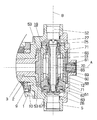
図2は、この発明の第2実施形態を示した図で、工具駆動モータ19をヘッドケース5に内蔵する場合の例を示した図である。以下、第1実施例と異なる部分についてのみ説明する。
FIG. 2 is a diagram showing a second embodiment of the present invention, and is a diagram showing an example in which the
工具駆動モータ19をヘッドケース5に内蔵した構造では、図1で説明した伝達軸4、これを軸支する軸受49、傘歯車15、16は不要である。固定軸3の先端に固定したインナーケース12には、その直径方向にモータ装着孔が設けられ、工具駆動モータ19は、そのハウジング68をこの工具装着孔に嵌合して固定した状態で装着されている。工具駆動モータ19は、回転磁界を発生するステータ69、当該磁界によって回転駆動されるロータ70及びロータを固定したロータ軸(工具駆動軸)13を備え、ロータ軸13は、軸受71、71でハウジング68に回転自在かつ軸方向移動不能に軸支されている。
In the structure in which the
ロータ軸13は中空軸で、その中空孔に連結軸65が挿通されている。連結軸65は、その先端(工具割出位置に向く端部)に嵌合溝27を備えており、ロータ軸13と連結軸65の先端側内周と外周は、スプライン66によって軸方向移動自在かつ相対回動不能に嵌合している。一方、連結軸65の後端には、軸受67でピストン63が相対回転可能かつ軸方向移動不能に装着されており、このピストン63は、工具駆動モータのハウジング68の後端に固定したシリンダケース62に嵌合している。シリンダケース62の後端側(連結軸65の後端側)に流体圧を供給すると、軸方向固定のロータ軸13に対して連結軸65が工具割出位置に向けて進出し、シリンダケース62の先端側に流体圧を供給すると、連結軸65が工具割出位置から退避する方向に後退する。
The
この第2実施形態においても、第1実施形態と同様に、ヘッドケース5を旋回して工具を割り出すときは、シリンダケース62の先端側に流体圧を供給して連結軸65を後退させる。割出位置に割り出された回転工具を駆動するときは、シリンダケース62の基端側に流体圧を供給して連結軸65を進出させ、嵌合溝27と回転工具ホルダの工具取付軸のタングとを密に嵌合させる。第1実施形態でも説明したように、回転工具を駆動するとき、連結軸65を常に進出させる必要は必ずしもなく、工具取付孔52に装着された工具ホルダの工具取付軸のタングと後退位置にある連結軸の嵌合溝27とのはめあい公差を適切に設定することにより、振動や衝撃的な負荷変動が生ずるおそれのない回転工具は、連結軸65を後退させたままの状態で回転駆動することが可能である。
Also in the second embodiment, as in the first embodiment, when the
この発明の構造による連結軸65の進退動作は、工具駆動軸13と回転工具との連結部の嵌合を密にするか緩めるか(タイトにするかルーズにするか)を選択しているので、その進退ストロークはわずかでよい。上記実施形態では、連結軸65にスプライン66を介して駆動力を伝達しているが、図3に示すように、円板状ないし放射状の板ばね75を用いて工具駆動軸13の回転を連結軸65に伝達することもできる。この場合連結軸65の軸方向移動は、板ばね75の撓みにより許容される。図3の板ばね75は、外周部76が工具駆動軸13の端部に固定され、内周部77が連結軸65の外周部に固定されているものである。
In the forward / backward movement of the connecting
また、上記実施形態においては、連結軸65を軸方向に進退させる機構として流体圧駆動のピストン63を用いているが、このピストンの代わりに電磁石(たとえばソレノイド)を用いることもできる。前述した工具駆動軸と連結軸との間の回転力の伝達手段として板ばね75を用いたときは、電磁石による吸引動作と、この板ばねの復帰力とによって連結軸65を進退させることができる。
In the above embodiment, the fluid pressure driven
連結軸65を進出させて回転工具側のタングと連結軸側の嵌合溝27との嵌合を密にすることによって弊害が生ずる場合がある。それは、連結軸65の軸心と工具割出位置に割り出された工具ホルダの工具取付軸の軸心とに芯ずれがある場合である。この弊害を避けるためには、連結軸65を進出方向に付勢するときの流体圧を制御して、嵌合溝27とタング26とが過大な力で嵌合されることがないようにするか、連結軸65の進出端を位置調整可能なストッパなどで調整できるようにして、嵌合溝27とタングとが過大な力で嵌合しないようにする。
An adverse effect may occur by advancing the connecting
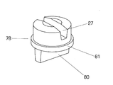
より好ましい構造は、図4に示すように、連結軸65の先端に工具取付軸25との軸心誤差を吸収する軸継手を設ける構造である。図4の例では、オールダム継手78が用いられている。図のオールダム継手78は、工具軸線Bと直交する第1の面と第2の面に互いに直行する方向の相対微小移動を許容する溝と突条との嵌合対を有する継手で、第1の嵌合対が連結軸65先端の溝79とオールダム継手の突条80で形成され、第2の嵌合対工具取付軸のタング26とこれを受け入れるオールダム継手の嵌合溝27とによって形成されるようにしたものである(図5参照)。オールダム継手78は、その外周に設けた鍔81を連結軸65の端面と、これに螺合したキャップ82の内側端面との間に放射方向に微小遊動可能にして軸方向移動不能に装着されているものである。
As shown in FIG. 4, a more preferable structure is a structure in which a shaft coupling that absorbs an axial error with respect to the
1 本体フレーム
2 中空割出軸
3 固定軸
4 伝達軸
5 ヘッドケース5
12 インナーケース
13 工具駆動軸
25 工具取付軸
26 タング
27 嵌合溝
29 回転工具
51 ヘッドケースの空室
63 進退装置(ピストン)
65 連結軸
75 板ばね
78 オールダム継手
A 割出軸線
B 工具軸線
DESCRIPTION OF
12 Inner case
13 Tool drive shaft
25 Tool mounting axis
26 tongue
27 Mating groove
29 Rotary tool
51 Headcase vacancy
63 Advance / Retreat Device (Piston)
65 Connecting shaft
75 leaf spring
78 Oldham Joint A Indexing axis B Tool axis
Claims (2)
前記工具駆動軸の軸心に軸方向移動可能かつ相対回動不能に設けられた連結軸(65)と、この連結軸を当該工具駆動軸に対してその軸方向に相対的に進退させる進退装置(63)と、外に向けて溝幅が広くなる台形断面の前記嵌合溝と、先端が薄くなる方向の台形断面の前記タングとを備え、
前記進退装置で連結軸を進出したときに、前記工具駆動軸の回転が当該連結軸及び密に嵌合した前記嵌合溝とタングとを介して回転工具に伝達され、
前記進退装置で連結軸を後退したときには、前記工具駆動軸の回転が当該連結軸及びタングが嵌合溝に側方から進入及び離脱するのに必要な微小隙間が存在する状態で嵌合した前記タングと嵌合溝とを介して回転工具に伝達されることを特徴とする、
回転工具タレット。 A head case (5) that pivots about the index axis (A) and indexes the rotary tool (29) mounted on the outer periphery thereof to the machining position, and an axis extending in a direction perpendicular to the index axis to the head case A tool drive shaft (13) connected to a rotary tool pivotally supported so as not to move in the direction and indexed to the machining position, and the connection is a fitting groove (27) facing the circumferential direction of the head case ) And a rotating tool turret performed by fitting with a tongue (26) inserted into the fitting groove from the side by index rotation of the head case,
A connecting shaft (65) provided in the axial center of the tool drive shaft so as to be movable in the axial direction and not relatively rotatable, and an advancing / retreating device for moving the connecting shaft relative to the tool drive shaft in the axial direction. (63), the fitting groove having a trapezoidal cross section in which the groove width becomes wider toward the outside, and the tongue having a trapezoidal cross section in a direction in which the tip is thinned,
Wherein when advancing the connecting shaft in advancing and retracting device, the rotation of the tool drive shaft is transmitted to the rotating tool through the fitting groove and tongue fitted to the connecting shaft and dense,
Wherein when retracting the connecting shaft in advancing and retracting device, the rotation of the tool drive shaft is fitted in a state where there are small gaps required for the connecting shaft and the tongue enters and detached from the side into the fitting groove characterized Rukoto is transmitted to the rotary tool through the tongue and groove,
Rotating tool turret.
当該連結装置は、前記ヘッドケースの周方向を向いた嵌合溝(27)とヘッドケースの割出し回転によって側方から当該嵌合溝に挿入及び離脱されるタング(26)とを備えている回転工具タレットにおいて、
前記連結装置が、前記工具駆動軸の軸心に軸方向移動可能かつ相対回動不能に設けた連結軸(65)と、この連結軸を前記工具駆動軸に対してその軸方向に相対的に進退させる進退装置(63)と、外に向けて溝幅が広くなる台形断面の前記嵌合溝と、先端が薄くなる方向の台形断面の前記タングとを備え、
前記連結軸を進出させたときに当該連結軸と前記割出された回転工具とが密に嵌合した前記嵌合溝とタングとを介して回転連結され、
当該連結軸が退避したときに当該連結軸と前記割出された回転工具とが、前記嵌合溝とタングとの間の相対滑りを可能にする微小隙間の存在によって緩められた状態で嵌合した前記嵌合溝とタングとを介して回転連結されることを特徴とする、回転工具タレット。 A hollow head case (5) that is swiveled and indexed about the index axis (A), and a tool drive shaft that is pivotally supported in a vacant space (51) of the head case with its tip directed in a fixed direction perpendicular to the axis. (13), and a coupling device that rotationally connects the rotary tool (29) attached to the head case and indexed in the direction in which the tip of the tool drive shaft faces, to the tool drive shaft,
The coupling device includes a fitting groove (27) facing the circumferential direction of the head case and a tongue (26) inserted into and removed from the fitting groove from the side by the indexing rotation of the head case. In the rotating tool turret,
The connecting device is provided with a connecting shaft (65) provided in the axial center of the tool driving shaft so as to be movable in the axial direction but not relatively rotatable, and the connecting shaft relative to the tool driving shaft in the axial direction. Advancing / retreating device (63), including the fitting groove having a trapezoidal cross section in which the groove width becomes wider toward the outside, and the tongue having a trapezoidal cross section in a direction in which the tip is thinned,
When the connecting shaft is advanced, the connecting shaft and the indexed rotary tool are rotationally connected via the fitting groove and tongue closely fitted ,
State the connecting shaft and the rotating tool in which the were indexed said a connecting shaft when retracted is was slow Merare by the presence of a small gap that allows the relative sliding between said fitting groove and the tongue in mated characterized Rukoto rotatably connected via the fitting groove and the tongue has, rotary tool turret.
Priority Applications (1)
| Application Number | Priority Date | Filing Date | Title |
|---|---|---|---|
| JP2006030034A JP4948844B2 (en) | 2006-02-07 | 2006-02-07 | Rotating tool turret |
Applications Claiming Priority (1)
| Application Number | Priority Date | Filing Date | Title |
|---|---|---|---|
| JP2006030034A JP4948844B2 (en) | 2006-02-07 | 2006-02-07 | Rotating tool turret |
Publications (2)
| Publication Number | Publication Date |
|---|---|
| JP2007210042A JP2007210042A (en) | 2007-08-23 |
| JP4948844B2 true JP4948844B2 (en) | 2012-06-06 |
Family
ID=38488897
Family Applications (1)
| Application Number | Title | Priority Date | Filing Date |
|---|---|---|---|
| JP2006030034A Active JP4948844B2 (en) | 2006-02-07 | 2006-02-07 | Rotating tool turret |
Country Status (1)
| Country | Link |
|---|---|
| JP (1) | JP4948844B2 (en) |
Cited By (1)
| Publication number | Priority date | Publication date | Assignee | Title |
|---|---|---|---|---|
| CN111788027A (en) * | 2018-10-26 | 2020-10-16 | 山崎马扎克公司 | Rotational force transmission mechanism, turret tool table, and lathe |
Families Citing this family (4)
| Publication number | Priority date | Publication date | Assignee | Title |
|---|---|---|---|---|
| JP4840287B2 (en) | 2007-08-10 | 2011-12-21 | 日産自動車株式会社 | Variable valve control device for internal combustion engine |
| KR200456102Y1 (en) * | 2008-01-08 | 2011-10-13 | 이더블유에스 코리아 주식회사 | Tool holder of the Tool Turret |
| JP5361563B2 (en) * | 2009-06-22 | 2013-12-04 | 株式会社ツガミ | lathe |
| DE102016001804A1 (en) * | 2016-02-17 | 2017-08-17 | Benz GmbH Werkzeugsysteme | Circulating tube magazine with moveable storage lids |
Family Cites Families (3)
| Publication number | Priority date | Publication date | Assignee | Title |
|---|---|---|---|---|
| JPH03277403A (en) * | 1990-03-22 | 1991-12-09 | Teijin Seiki Co Ltd | Tool post device |
| JP2654331B2 (en) * | 1993-04-15 | 1997-09-17 | 日清紡績株式会社 | Power transmission device for multi-head machining unit |
| JP4251630B2 (en) * | 2003-12-17 | 2009-04-08 | 株式会社森精機製作所 | Machine tool turret |
-
2006
- 2006-02-07 JP JP2006030034A patent/JP4948844B2/en active Active
Cited By (3)
| Publication number | Priority date | Publication date | Assignee | Title |
|---|---|---|---|---|
| CN111788027A (en) * | 2018-10-26 | 2020-10-16 | 山崎马扎克公司 | Rotational force transmission mechanism, turret tool table, and lathe |
| CN111788027B (en) * | 2018-10-26 | 2022-02-22 | 山崎马扎克公司 | Rotational force transmission mechanism, turret tool table, and lathe |
| US11583932B2 (en) | 2018-10-26 | 2023-02-21 | Yamazaki Mazak Corporation | Rotational force transmission mechanism, turret tool rest, and lathe |
Also Published As
| Publication number | Publication date |
|---|---|
| JP2007210042A (en) | 2007-08-23 |
Similar Documents
| Publication | Publication Date | Title |
|---|---|---|
| JP4488375B2 (en) | Machine tool spindle equipment | |
| JP4948844B2 (en) | Rotating tool turret | |
| JP6425601B2 (en) | Tool post of machine tool | |
| JP3183660U (en) | Tool holder for mounting non-rotating tools of machining centers | |
| EP1808267A1 (en) | Tool turret | |
| US7287940B2 (en) | Device for fixing a tool on a shaft and machine spindle comprising same | |
| JP4609337B2 (en) | Turret lathe | |
| KR100653511B1 (en) | Turret tool apparatus adjustable the forward and backward positions of drive shaft which drive the driven-tool | |
| KR101682558B1 (en) | Electrically Driven Turret System and Method for Working the System | |
| JP5411686B2 (en) | Machining tool holder | |
| JP3793107B2 (en) | Radial cutting drive device for rotary tools | |
| JP2003251505A (en) | Rotary tool turret for lathe | |
| JP4616725B2 (en) | Tapping unit | |
| JP4771301B2 (en) | Turret tool post | |
| JP2010023207A (en) | Turret dividing device | |
| JP5368965B2 (en) | Valve seat machining tool | |
| JP2008055576A (en) | Rotary tool turret | |
| JPH10138013A (en) | Radial cross feed device for machine tool | |
| JP2002086304A (en) | Spindle device | |
| JP2001287109A (en) | Machining method by machine tool and machine tool | |
| KR102374050B1 (en) | Millhead for Composite Machine Tool | |
| JP4721894B2 (en) | Cutting device | |
| JP5345460B2 (en) | U-axis drive structure of machine tool | |
| JP2004025404A (en) | Rotary tool turret | |
| JP4261663B2 (en) | Rotating tool holder and machine tool using the same |
Legal Events
| Date | Code | Title | Description |
|---|---|---|---|
| A621 | Written request for application examination |
Free format text: JAPANESE INTERMEDIATE CODE: A621 Effective date: 20081222 |
|
| A977 | Report on retrieval |
Free format text: JAPANESE INTERMEDIATE CODE: A971007 Effective date: 20110615 |
|
| A131 | Notification of reasons for refusal |
Free format text: JAPANESE INTERMEDIATE CODE: A131 Effective date: 20110621 |
|
| A521 | Request for written amendment filed |
Free format text: JAPANESE INTERMEDIATE CODE: A523 Effective date: 20110819 |
|
| A131 | Notification of reasons for refusal |
Free format text: JAPANESE INTERMEDIATE CODE: A131 Effective date: 20111018 |
|
| A521 | Request for written amendment filed |
Free format text: JAPANESE INTERMEDIATE CODE: A523 Effective date: 20111215 |
|
| TRDD | Decision of grant or rejection written | ||
| A01 | Written decision to grant a patent or to grant a registration (utility model) |
Free format text: JAPANESE INTERMEDIATE CODE: A01 Effective date: 20120207 |
|
| A01 | Written decision to grant a patent or to grant a registration (utility model) |
Free format text: JAPANESE INTERMEDIATE CODE: A01 |
|
| A61 | First payment of annual fees (during grant procedure) |
Free format text: JAPANESE INTERMEDIATE CODE: A61 Effective date: 20120307 |
|
| FPAY | Renewal fee payment (event date is renewal date of database) |
Free format text: PAYMENT UNTIL: 20150316 Year of fee payment: 3 |
|
| R150 | Certificate of patent or registration of utility model |
Ref document number: 4948844 Country of ref document: JP Free format text: JAPANESE INTERMEDIATE CODE: R150 Free format text: JAPANESE INTERMEDIATE CODE: R150 |
|
| R250 | Receipt of annual fees |
Free format text: JAPANESE INTERMEDIATE CODE: R250 |
|
| R250 | Receipt of annual fees |
Free format text: JAPANESE INTERMEDIATE CODE: R250 |
|
| R250 | Receipt of annual fees |
Free format text: JAPANESE INTERMEDIATE CODE: R250 |
|
| R250 | Receipt of annual fees |
Free format text: JAPANESE INTERMEDIATE CODE: R250 |