JP4261663B2 - Rotating tool holder and machine tool using the same - Google Patents
Rotating tool holder and machine tool using the same Download PDFInfo
- Publication number
- JP4261663B2 JP4261663B2 JP02950799A JP2950799A JP4261663B2 JP 4261663 B2 JP4261663 B2 JP 4261663B2 JP 02950799 A JP02950799 A JP 02950799A JP 2950799 A JP2950799 A JP 2950799A JP 4261663 B2 JP4261663 B2 JP 4261663B2
- Authority
- JP
- Japan
- Prior art keywords
- tool
- holder
- housing
- predetermined direction
- shaft
- Prior art date
- Legal status (The legal status is an assumption and is not a legal conclusion. Google has not performed a legal analysis and makes no representation as to the accuracy of the status listed.)
- Expired - Lifetime
Links
Images
Landscapes
- Cutting Tools, Boring Holders, And Turrets (AREA)
Description
【0001】
【発明の属する技術分野】
本発明は、タレット旋盤等の工作機械にドリルやエンドミル等の回転工具を装着して穴あけ加工等を行うための回転工具ホルダおよびそれを用いた工作機械に関する。
【0002】
【従来の技術】
タレット旋盤による加工方法の一つとして、例えば図7に示すようにタレットタイプの刃物台1に工具ホルダ2を介してドリル等の回転工具3を装着し、刃物台1側から工具ホルダ2に伝達される動力にてその回転工具3を回転させることにより、主軸4上のチャック5に把持されたワーク(不図示)の端面に穴あけ加工等を行なう方法が知られている。
【0003】
ところで、一般的な旋盤の刃物台1は、主軸4の軸線と平行なZ軸方向と、これに直交するX軸方向の二方向にしか移動できない。そのため、回転工具3を刃物台1に取り付けた状態で回転工具3にY軸方向(刃物台1の回転方向に対する接線方向であり、図7では紙面と直交する方向に相当する。)のずれが生じている場合にはそれを調整できず、主軸4に対して芯のずれた状態で加工が行われる。
【0004】
そこで、従来の回転工具ホルダには、刃物台1に対して回転工具3をY軸方向に変位させる調整機構が設けられている。
【0005】
【発明が解決しようとする課題】
ところが、従来の回転工具ホルダのY軸方向の調整機構は、刃物台から回転工具に至る回転伝達系内に一対の平歯車を設け、それら平歯車の噛み合いが損なわれない範囲で一方の平歯車を他方の平歯車に対して変位させて回転工具のY軸方向の位置を変化させるものであった。しかしながら、このような調整機構では、一対の平歯車をそれぞれ保持するために互いに平行な一対の回転軸を回転伝達系内に設ける必要がある。従って、機構を構成する部品数が増加して機構が複雑化し、製造コストが上昇する。また、部品数の増加により、工具ホルダが大きくなる。
【0006】
そこで、本発明は、従来よりも少ない部品で回転工具をその軸線と直交する方向(例えば上述したY軸方向)に変位させることができる回転工具ホルダおよびそれを用いた工作機械を提供することを目的とする。
【0007】
【課題を解決するための手段】
以下、本発明について説明する。なお、本発明の理解を容易にするために添付図面の参照符号を括弧書きにて付記するが、それにより本発明が図示の形態に限定されるものではない。
【0008】
請求項1の発明は、工作機械の刃物保持部(1)に装着されるホルダ本体(11)と、回転工具(3)が同軸的に装着される工具軸(23)と、前記工具軸をその軸線回りに回転可能に支持するとともに前記ホルダ本体に対して前記工具軸の軸線と直交する所定方向(Y)に変位可能に組み合わされるハウジング(12)とを具備し、前記ホルダ本体には、前記工作機械から供給される回転を前記工具軸に伝達するための駆動軸(16)がその軸線を前記工具軸の軸線方向(Z)および前記所定方向の両者と直交する方向(X)に向けて装着され、前記駆動軸から前記工具軸へは一対のかさ歯車(17,25)を介して回転が伝達可能とされ、前記一対のかさ歯車のそれぞれには、前記ホルダ本体に対する前記ハウジングの前記所定方向(Y)への変位を許容するためにクラウニング加工が施され、前記ホルダ本体には、前記所定方向へ螺進退可能に調整ネジ(35)が取り付けられ、前記ハウジングからは前記調整ネジに形成された環状溝(35a)内へとピン(36)が突出し、前記調整ネジを回すことにより、前記環状溝及びピンを介して前記ハウジング(12)を前記ホルダ本体(11)に対し前記所定方向(Y)に移動させると、それに伴って前記一対のかさ歯車(17,25)の芯が前記所定方向(Y)にずれるようにしたことを特徴とする回転工具ホルダにより、上述した課題を解決する。
【0009】
クラウニング加工は、歯車の歯厚を歯すじの中央部から歯すじ端に向かって連続的に減少させる処理として知られており、一般には歯車の片当たりによる応力集中の回避を目的として行われる。本願の発明者は、かさ歯車の芯ずれを許容する手段としてクラウニング加工が効果的であることを見いだして本発明に至ったものである。すなわち、本発明によれば、かさ歯車に施されたクラウニング加工により、かさ歯車間の芯ずれがある程度許容されるようになるので、工具軸を保持するハウジングをホルダ本体に対して駆動軸の軸線方向と直交する方向にある程度変位させることができる。この変位の方向を例えばタレット旋盤におけるY軸方向と一致させておけば、平歯車による調整機構を介在させなくても回転工具の位置をY軸方向に変位させて主軸に対する芯ずれを解消することができる。
【0010】
なお、請求項2に記載したように、前記ホルダ本体(11)と前記ハウジング(12)との間には、前記所定方向に延びるキー(24)を設けてもよい。これにより、ハウジングを所定方向に正確に変位させることができる。
【0011】
請求項3の発明は、機械主軸(4)に対して当該機械主軸の軸線方向(Z軸方向)およびその軸線方向と直交する一方向(X軸方向)に相対的に移動可能な刃物保持部(1)と、その刃物保持部に装着される回転工具ホルダ(10)とを具備する工作機械において、前記回転工具ホルダは、前記刃物保持部に装着されるホルダ本体(11)と、前記機械主軸と平行に配置され、回転工具(3)が同軸的に装着される工具軸(23)と、前記工具軸をその軸線回りに回転可能に支持するとともに前記ホルダ本体に対して前記工具軸の軸線と直交しかつ前記一方向とは異なる所定方向(例えばY軸方向)に変位可能に組み合わされるハウジング(12)とを具備し、前記ホルダ本体には、前記工作機械から供給される回転を前記工具軸に伝達するための駆動軸(16)がその軸線を前記工具軸の軸線方向および前記所定方向の両者と直交する方向に向けて装着され、前記駆動軸から前記工具軸へは一対のかさ歯車(17,25)を介して回転が伝達可能とされ、前記一対のかさ歯車のそれぞれには、前記ホルダ本体に対する前記ハウジングの前記所定方向への変位を許容するためにクラウニング加工が施され、前記ホルダ本体には、前記所定方向へ螺進退可能に調整ネジ(35)が取り付けられ、前記ハウジングからは前記調整ネジに形成された環状溝(35a)内へとピン(36)が突出し、前記調整ネジを回すことにより、前記環状溝及びピンを介して前記ハウジング(12)を前記ホルダ本体(11)に対し前記所定方向(Y)に移動させると、それに伴って前記一対のかさ歯車(17,25)の芯が前記所定方向(Y)にずれるようにしたことにより、上述した課題を解決する。
【0012】
この発明においても、上述した請求項1の発明と同様の理由により、平歯車による調整機構を介在させなくても回転工具の位置を例えばY軸方向に変位させてワークに対する芯ずれを解消することができる。
【0013】
なお、請求項3に記載したように、前記刃物保持部はタレットタイプの刃物台(1)とすることができ、前記駆動軸の軸線方向は前記刃物台の半径方向に一致させることができる。これにより、刃物台の中心側から駆動軸に回転を供給して回転工具を回転させることができる。しかも、ハウジングをホルダ本体に対して変位させることにより、回転工具の位置を刃物台の回転方向に対する接線方向に調整できる。
【0014】
【発明の実施の形態】
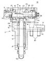
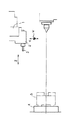
図1〜図5は本発明の一実施形態の回転工具ホルダ10の詳細を示し、図6はその工具ホルダ10の使用状態を示す図である。図6から明らかなように、本実施形態の工具ホルダ10は、旋盤のタレットタイプの刃物台(工具保持部)1のスロット1aに取り付けられ、刃物台1のカバー1bの内側に設けられた回転駆動機構の出力軸(不図示)から供給される回転をチャック32に伝達してそこに把持されたドリル等の回転工具3を回転させるために使用される。刃物台1と旋盤の主軸(機械主軸)4との関係は図7に示した通りであり、刃物台1はZ軸方向およびX軸方向に移動可能かつZ軸方向に延びる中心線の回りに旋回可能である。
【0015】
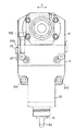
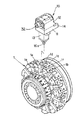
図1および図2に示すように、回転工具ホルダ10は、ホルダ本体11と、その取付面11a上に取り付けられたスピンドルハウジング12とを有している。ホルダ本体11は、断面矩形状のシャンク13と、そのシャンク13の後方に延びるフランジ14とを具備し、フランジ14の下面にはキー溝14aが設けられている。ホルダ10を図6の刃物台1に装着する際に、シャンク13はスロット1aに嵌合し、フランジ14は刃物台1の取付面1cに突き当てられ、キー溝14aは刃物台1のキー溝1dに装着される不図示のキーと嵌合する。そして、シャンク13の両側に装着される2本のボルト100,100(図2参照)と、フランジ14に装着される4本のボルト101…101(図1参照)とが、図6に示す刃物台1のねじ穴1e,1fにそれぞれねじ込まれてホルダ10が刃物台1に固定される。
【0016】
図1および図2に示すように、シャンク13の内部には一対のベアリング15,15を介して駆動軸16が回転自在に装着されている。駆動軸16の一端(図1の下端)はシャンク13から突出し、その突出部分には平板状の爪16aが形成されている。爪16aは図6の刃物台1のカバー1bの内側に挿入され、刃物台1に内蔵された回転駆動機構の出力軸(不図示)の軸端に設けられた溝と嵌合する。これにより、刃物台1側から供給される動力にて駆動軸16をその軸線回りに回転させることが可能となる。なお、工具ホルダ10が刃物台1に取り付けられたとき、駆動軸16の軸線方向は刃物台1の半径方向と一致する。
【0017】
一方、駆動軸16の他端(図1の上端)は取付面11aから突出し、その突出部分にはかさ歯車17が取り付けられている。かさ歯車17と駆動軸16との間には、両者を一体回転させるためのキー18,18が設けられる。駆動軸16の軸端にはかさ歯車17を抜け止めするためのストッパ19が取り付けられる。
【0018】
ハウジング12の内部にはベアリング21,22を介してスピンドル(工具軸)23が取り付けられている。ハウジング12は、ホルダ本体11の取付面11a上に載置され、4本(図2に1本のみ示す。)のボルト102によりホルダ本体11に固定される。取付面11aとハウジング12との間には、Y軸方向(図2の矢印Y方向)に延びる一対のキー24,24が設けられている。従って、ボルト102を緩めた場合には、ハウジング12をキー24,24に沿ってY軸方向に変位させることができる。
【0019】
スピンドル23にはかさ歯車25が取り付けられている。かさ歯車25は駆動軸16上のかさ歯車17と噛み合わされ、それにより駆動軸16からスピンドル23への回転伝達が可能となる。かさ歯車25とスピンドル23との間には両者を一体回転させるためのキー26が装着される。
【0020】
スピンドル23の先端(図1の左端)には、リングナット31と、そのリングナット31の内側に保持されたコレットチャック32とが設けられている。リングナット31を回転させると、コレットチャック32がスピンドル23のテーパ穴23aに対して軸方向に変位してその内径が変化する。これにより、ドリル等の回転工具3(図6参照)に設けられたシャンクがコレットチャック32に把持され、またはコレットチャック32から解放される。
【0021】
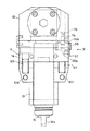
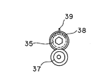
図2および図3に示すように、ホルダ本体11の一側には調整ねじ35がその軸線をY軸方向に一致させてねじ込まれている。調整ねじ35の外周には環状溝35a、35bが形成されている。ホルダ本体11内に位置する環状溝35aには、ハウジング12に取り付けられたピン36がホルダ本体11に設けられた通し穴11bを貫いて嵌合する。ホルダ本体11に対するハウジング12のY軸方向の変位を許容するため、通し穴11bはピン36よりも大きく設定されている。調整ねじ35を回転させるとピン36を介してハウジング12がY軸方向に移動する。調整ねじ35の環状溝35bには、ホルダ本体11の側面に固定されたストッパ37がY軸方向に多少の隙間を設けた状態で係合する。これにより調整ねじ35が抜け止めされる。図4に示したように、調整ねじ35の端面には一定間隔で目盛38が付されている。これらの目盛38とホルダ本体11に設けられた基準線39とによってハウジング12の移動量を把握できる。
【0022】
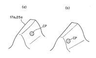
以上のように、本実施形態の工具ホルダ10においては、ボルト102(図2参照)を緩めて調整ねじ35を操作することにより、ハウジング12をキー24に沿って移動させることができる。従って、コレットチャック32に装着された回転工具3をY軸方向に変位させてワークに対する芯ずれを解消することができる。ただし、駆動軸16からスピンドル23への回転伝達を一対のかさ歯車17,25にて行っているので、ハウジング12をホルダ本体11に対してY軸方向に移動させると、それに伴ってかさ歯車17,25の芯がY軸方向にずれることになる。一般に、かさ歯車間に芯ずれが生じていると、図5(b)に示したように、歯面の接触箇所CPが歯すじ方向の端部に偏るいわゆるクロス当たりが生じ、歯車の寿命が低下したり、騒音が増加する等の不都合が生じる。
【0023】
そこで、本実施形態では、図5(a)に示したようにかさ歯車17,25の歯部17a、25aをクラウニング加工している。これにより、歯車同士に芯ずれがあっても、従来のものと比較して歯面の接触箇所CPが歯すじ方向の中央部に変位し、歯面の異常摩耗や騒音増加を防止できる。その結果、クラウニング加工を施さない場合と比較して、芯ずれの許容量、換言すればハウジング12のY軸方向への移動量を大きく設定できるようになる。クラウニング量が大きいほどY軸方向への移動量を大きく設定できるが、クラウニング量の増加に伴って接触箇所CPの面積が減少して面圧が増加する。この点を考慮してクラウニング量を決定する必要がある。ちなみに、発明者らの検討によれば、モジュール2.5,歯数17,歯幅10mmの場合で、クラウニング量を0.07程度に設定することにより、ハウジング12をY軸方向に±0.1mm程度変位させ得ることが確認されている。なお、図6では、歯部17a,25aを歯すじが直線的なすぐ歯として描いているが、歯部17a,25aは曲がり歯でもよい。
【0024】
本発明は上述した実施形態に限定されず、種々の形態にて実施できる。例えば、ホルダ本体11の形状や刃物台1への取付構造は種々変更できる。ハウジング12の形状も実施例のものに限定されない。本発明の工具ホルダは、タレット旋盤の刃物台に限らず、工具ホルダ自身で回転工具をその軸線方向と直交する方向に変位させる必要のある各種の工作機械に適用できる。
【0025】
【発明の効果】
以上に説明したように、本発明によれば、工具ホルダ内の駆動軸から工具軸へと回転を伝達するかさ歯車にクラウニング処理を施すことにより、両軸間の芯ずれを許容して工具軸に取り付けられる回転工具をその軸線方向と直交する方向に変位可能としたため、平歯車を利用した従来の調整機構のように互いに平行な一対の軸を設ける必要がなく、工具ホルダを構成する部品数を減らしてホルダの内部機構を簡素化できる。これにより製造コストを低減できるとともに、工具ホルダをコンパクトに構成できる。そして、工具ホルダの小型化により、それが装着されるタレット旋盤等の工作機械の刃物保持部の周囲の干渉領域を減らしてその動作範囲を拡大できる等の優れた効果が得られる。
【図面の簡単な説明】
【図1】本発明の一実施形態に係る工具ホルダの断面図。
【図2】図1の工具ホルダの正面図。
【図3】図1の工具ホルダの背面図。
【図4】図3のIV方向からの矢視図。
【図5】クラウニング加工を説明するための図。
【図6】図1の工具ホルダの使用状態を示す図。
【図7】タレット旋盤における刃物台と機械主軸との関係を示す図。
【符号の説明】
1 刃物台
3 回転工具
4 主軸(機械主軸)
5 チャック
10 回転工具ホルダ
11 ホルダ本体
11a 取付面
12 スピンドルハウジング
13 シャンク
16 駆動軸
17,25 かさ歯車
23 スピンドル(工具軸)
24 キー
31 リングナット
32 コレットチャック[0001]
BACKGROUND OF THE INVENTION
The present invention relates to a rotary tool holder for mounting a rotary tool such as a drill or an end mill on a machine tool such as a turret lathe for drilling and the like, and a machine tool using the rotary tool holder.
[0002]
[Prior art]
As one of processing methods using a turret lathe, for example, as shown in FIG. 7, a rotating tool 3 such as a drill is attached to a turret type tool post 1 via a tool holder 2 and transmitted from the tool post 1 side to the tool holder 2. There is known a method of drilling or the like in the end face of a work (not shown) gripped by a chuck 5 on a main shaft 4 by rotating the rotary tool 3 with a motive power.
[0003]
By the way, a general lathe tool post 1 can move only in two directions: a Z-axis direction parallel to the axis of the main shaft 4 and an X-axis direction orthogonal thereto. Therefore, with the rotary tool 3 attached to the tool post 1, there is a shift in the Y-axis direction (which is a tangential direction with respect to the rotational direction of the tool post 1 and corresponds to a direction orthogonal to the paper surface in FIG. 7). If it occurs, it cannot be adjusted, and the machining is performed in a state where the core is displaced from the main shaft 4.
[0004]
Therefore, the conventional rotary tool holder is provided with an adjustment mechanism for displacing the rotary tool 3 in the Y-axis direction with respect to the tool post 1.
[0005]
[Problems to be solved by the invention]
However, the conventional adjustment mechanism in the Y-axis direction of the rotary tool holder is provided with a pair of spur gears in a rotation transmission system from the tool post to the rotary tool, and one spur gear is within a range in which the meshing of these spur gears is not impaired. Is displaced with respect to the other spur gear to change the position of the rotary tool in the Y-axis direction. However, in such an adjustment mechanism, it is necessary to provide a pair of rotation shafts parallel to each other in the rotation transmission system in order to hold the pair of spur gears. Therefore, the number of parts constituting the mechanism increases, the mechanism becomes complicated, and the manufacturing cost increases. In addition, the tool holder becomes larger as the number of parts increases.
[0006]
Therefore, the present invention provides a rotary tool holder capable of displacing a rotary tool in a direction orthogonal to the axis thereof (for example, the Y-axis direction described above) with fewer parts than before, and a machine tool using the rotary tool holder. Objective.
[0007]
[Means for Solving the Problems]
The present invention will be described below. In order to facilitate understanding of the present invention, reference numerals in the accompanying drawings are appended in parentheses, but the present invention is not limited to the illustrated embodiment.
[0008]
The invention of claim 1 includes a holder main body (11) mounted on a blade holding part (1) of a machine tool, a tool shaft (23) on which a rotary tool (3) is mounted coaxially, and the tool shaft. A housing (12) that is rotatably supported about the axis and is displaceable in a predetermined direction (Y) perpendicular to the axis of the tool axis with respect to the holder body. The drive shaft (16) for transmitting the rotation supplied from the machine tool to the tool shaft has its axis directed in the direction (X) perpendicular to both the axial direction (Z) of the tool shaft and the predetermined direction. The rotation can be transmitted from the drive shaft to the tool shaft via a pair of bevel gears (17, 25), and each of the pair of bevel gears has the housing of the housing relative to the holder body. Predetermined direction (Y The holder body is provided with an adjustment screw (35) that can be screwed back and forth in the predetermined direction, and an annular groove formed in the adjustment screw from the housing. The pin (36) protrudes into (35a), and the housing (12) is moved in the predetermined direction (Y) with respect to the holder body (11) via the annular groove and the pin by turning the adjusting screw. The rotary tool holder is characterized in that, when moved, the core of the pair of bevel gears (17, 25) is displaced in the predetermined direction (Y) .
[0009]
The crowning process is known as a process of continuously reducing the tooth thickness of the gear from the central portion of the tooth trace toward the end of the tooth trace, and is generally performed for the purpose of avoiding stress concentration due to the contact of the gear. The inventor of the present application has found that the crowning process is effective as a means for allowing the bevel gear to be misaligned, and has reached the present invention. In other words, according to the present invention, the misalignment between the bevel gears is allowed to some extent by the crowning process applied to the bevel gears, so that the housing holding the tool shaft is the axis of the drive shaft with respect to the holder body. It can be displaced to some extent in a direction orthogonal to the direction. If the direction of this displacement coincides with, for example, the Y-axis direction in the turret lathe, the position of the rotary tool is displaced in the Y-axis direction without using a spur gear adjusting mechanism to eliminate misalignment with respect to the main shaft. Can do.
[0010]
In addition, you may provide the key (24) extended in the said predetermined direction between the said holder main body (11) and the said housing (12) as described in Claim 2. Thereby, the housing can be accurately displaced in a predetermined direction.
[0011]
The invention according to claim 3 is a blade holder that is relatively movable with respect to the machine spindle (4) in the axial direction (Z-axis direction) of the machine spindle and in one direction (X-axis direction) orthogonal to the axis direction. (1) and a rotary tool holder (10) mounted on the blade holder, wherein the rotary tool holder includes a holder body (11) mounted on the blade holder, and the machine A tool shaft (23) disposed in parallel with the main shaft and coaxially mounted with the rotary tool (3), and supports the tool shaft so as to be rotatable about its axis, and the tool shaft with respect to the holder body. A housing (12) that is orthogonal to the axis and is displaceably combined in a predetermined direction (for example, the Y-axis direction) different from the one direction, and the holder body receives the rotation supplied from the machine tool. Transmit to the tool axis A drive shaft (16) is mounted with its axis line oriented in a direction orthogonal to both the axial direction of the tool axis and the predetermined direction, and a pair of bevel gears (17, 25) is provided from the drive shaft to the tool axis. ), And each of the pair of bevel gears is crowned to allow displacement of the housing in the predetermined direction with respect to the holder body. An adjustment screw (35) is attached so as to be capable of screwing back and forth in the predetermined direction, and a pin (36) protrudes from the housing into an annular groove (35a) formed in the adjustment screw, and the adjustment screw is turned. by, moving the a predetermined direction (Y) with respect to the said housing (12) via the annular groove and the pin holder body (11), said pair of bevel gears along with it By
[0012]
Also in this invention, for the same reason as in the first aspect of the invention described above, the misalignment with respect to the workpiece is eliminated by displacing the position of the rotary tool in the Y-axis direction, for example, without interposing an adjustment mechanism using a spur gear. Can do.
[0013]
In addition, as described in claim 3, the tool holder can be a turret type tool post (1), and the axial direction of the drive shaft can coincide with the radial direction of the tool post. Thereby, rotation can be supplied to a drive shaft from the center side of a tool post, and a rotary tool can be rotated. Moreover, by displacing the housing with respect to the holder body, the position of the rotary tool can be adjusted in a tangential direction with respect to the direction of rotation of the tool post.
[0014]
DETAILED DESCRIPTION OF THE INVENTION
1 to 5 show details of the
[0015]
As shown in FIGS. 1 and 2, the
[0016]
As shown in FIGS. 1 and 2, a
[0017]
On the other hand, the other end (upper end in FIG. 1) of the
[0018]
A spindle (tool axis) 23 is attached to the inside of the
[0019]
A
[0020]
A
[0021]
As shown in FIGS. 2 and 3, an
[0022]
As described above, in the
[0023]
Therefore, in this embodiment, as shown in FIG. 5A, the tooth portions 17a and 25a of the bevel gears 17 and 25 are crowned. As a result, even if there is a misalignment between the gears, the contact point CP of the tooth surface is displaced to the central portion in the tooth line direction as compared with the conventional one, and abnormal wear of the tooth surface and an increase in noise can be prevented. As a result, compared to the case where no crowning is performed, an allowable amount of misalignment, in other words, a movement amount of the
[0024]
The present invention is not limited to the embodiments described above, and can be implemented in various forms. For example, the shape of the holder
[0025]
【The invention's effect】
As described above, according to the present invention, the bevel gear that transmits the rotation from the drive shaft in the tool holder to the tool shaft is subjected to a crowning process to allow misalignment between the two shafts. The rotary tool attached to the tool holder can be displaced in the direction perpendicular to the axial direction thereof, so there is no need to provide a pair of shafts parallel to each other as in the conventional adjustment mechanism using a spur gear, and the number of parts constituting the tool holder Can be reduced and the internal mechanism of the holder can be simplified. Thereby, while being able to reduce manufacturing cost, a tool holder can be comprised compactly. Further, by reducing the size of the tool holder, it is possible to obtain an excellent effect that the operation range can be expanded by reducing the interference area around the blade holder of a machine tool such as a turret lathe to which the tool holder is mounted.
[Brief description of the drawings]
FIG. 1 is a cross-sectional view of a tool holder according to an embodiment of the present invention.
FIG. 2 is a front view of the tool holder of FIG.
FIG. 3 is a rear view of the tool holder of FIG. 1;
4 is an arrow view from the direction IV in FIG. 3;
FIG. 5 is a diagram for explaining crowning processing;
6 is a view showing a usage state of the tool holder of FIG. 1. FIG.
FIG. 7 is a diagram showing a relationship between a tool post and a machine spindle in a turret lathe.
[Explanation of symbols]
1 Tool post 3 Rotating tool 4 Spindle (machine spindle)
5 Chuck 10
24
Claims (4)
前記ホルダ本体には、前記所定方向へ螺進退可能に調整ネジが取り付けられ、前記ハウジングからは前記調整ネジに形成された環状溝内へとピンが突出し、前記調整ネジを回すことにより、前記環状溝及びピンを介して前記ハウジングを前記ホルダ本体に対し前記所定方向に移動させると、それに伴って前記一対のかさ歯車の芯が前記所定方向にずれるようにしたことを特徴とする工作機械。In a machine tool comprising a cutter holder that is movable relative to a machine spindle in an axial direction of the machine spindle and a direction orthogonal to the axis direction, and a rotary tool holder attached to the cutter holder. The rotary tool holder includes a holder main body mounted on the blade holder, a tool shaft disposed in parallel to the machine main shaft, and the rotary tool mounted coaxially, and the tool shaft rotates about its axis. A housing that supports the holder main body and is displaceable in a predetermined direction different from the one direction perpendicular to the axis of the tool axis with respect to the holder main body. A drive shaft for transmitting the supplied rotation to the tool shaft is mounted with its axis line oriented in a direction orthogonal to both the axial direction of the tool shaft and the predetermined direction, and the drive shaft The rotation can be transmitted to the tool shaft via a pair of bevel gears, and each of the pair of bevel gears is subjected to crowning to allow displacement of the housing in the predetermined direction with respect to the holder body. Is given,
An adjustment screw is attached to the holder body so as to be capable of screwing back and forth in the predetermined direction. A pin projects from the housing into an annular groove formed in the adjustment screw. A machine tool characterized in that when the housing is moved in the predetermined direction with respect to the holder body via a groove and a pin, the cores of the pair of bevel gears are displaced in the predetermined direction accordingly .
Priority Applications (1)
| Application Number | Priority Date | Filing Date | Title |
|---|---|---|---|
| JP02950799A JP4261663B2 (en) | 1999-02-08 | 1999-02-08 | Rotating tool holder and machine tool using the same |
Applications Claiming Priority (1)
| Application Number | Priority Date | Filing Date | Title |
|---|---|---|---|
| JP02950799A JP4261663B2 (en) | 1999-02-08 | 1999-02-08 | Rotating tool holder and machine tool using the same |
Publications (2)
| Publication Number | Publication Date |
|---|---|
| JP2000225508A JP2000225508A (en) | 2000-08-15 |
| JP4261663B2 true JP4261663B2 (en) | 2009-04-30 |
Family
ID=12278017
Family Applications (1)
| Application Number | Title | Priority Date | Filing Date |
|---|---|---|---|
| JP02950799A Expired - Lifetime JP4261663B2 (en) | 1999-02-08 | 1999-02-08 | Rotating tool holder and machine tool using the same |
Country Status (1)
| Country | Link |
|---|---|
| JP (1) | JP4261663B2 (en) |
Families Citing this family (2)
| Publication number | Priority date | Publication date | Assignee | Title |
|---|---|---|---|---|
| WO2026053345A1 (en) * | 2024-09-05 | 2026-03-12 | 株式会社Fuji | Tool holder adapter |
| JP7720973B1 (en) * | 2024-09-06 | 2025-08-08 | Dmg森精機株式会社 | Turrets and machine tools |
-
1999
- 1999-02-08 JP JP02950799A patent/JP4261663B2/en not_active Expired - Lifetime
Also Published As
| Publication number | Publication date |
|---|---|
| JP2000225508A (en) | 2000-08-15 |
Similar Documents
| Publication | Publication Date | Title |
|---|---|---|
| EP0378239A2 (en) | Transmission device | |
| KR101157326B1 (en) | Cross tool holder to adjust angle | |
| JP4261663B2 (en) | Rotating tool holder and machine tool using the same | |
| JP2002137132A (en) | Tip positioning mechanism of tool | |
| KR100859349B1 (en) | Angle head with adjustable angle | |
| JP4609337B2 (en) | Turret lathe | |
| US2915949A (en) | End mill driving attachment | |
| JP2003251505A (en) | Rotary tool turret for lathe | |
| JP3793107B2 (en) | Radial cutting drive device for rotary tools | |
| JP2002011616A (en) | Gear cutting tool and gear cutting method | |
| JP4948844B2 (en) | Rotating tool turret | |
| JPH04365503A (en) | U axis boring head | |
| JPH0533201Y2 (en) | ||
| JP2992569B2 (en) | Lathe guide bush device | |
| JP4126193B2 (en) | Valve seat machining tool device | |
| JP4027486B2 (en) | NC lathe with gear cutting device | |
| CN121004467B (en) | A high-rigidity milling and turning composite power tool spindle structure | |
| JP2002307218A (en) | High-speed boring shaft head that can handle multiple diameters | |
| JPH0144254Y2 (en) | ||
| JPH0713925Y2 (en) | Tool holder for taper hole machining | |
| JPH079208A (en) | Indexing tool post of NC lathe | |
| JP4566315B2 (en) | Cutting method | |
| JPH11347812A (en) | Taper circumferential face cutting tool | |
| RU2101139C1 (en) | Device to lathe for cutting of hourglass worms | |
| JP2004017208A (en) | Double chuck unit |
Legal Events
| Date | Code | Title | Description |
|---|---|---|---|
| A621 | Written request for application examination |
Free format text: JAPANESE INTERMEDIATE CODE: A621 Effective date: 20051222 |
|
| A977 | Report on retrieval |
Free format text: JAPANESE INTERMEDIATE CODE: A971007 Effective date: 20080403 |
|
| A131 | Notification of reasons for refusal |
Free format text: JAPANESE INTERMEDIATE CODE: A131 Effective date: 20080722 |
|
| A521 | Written amendment |
Free format text: JAPANESE INTERMEDIATE CODE: A523 Effective date: 20080917 |
|
| A131 | Notification of reasons for refusal |
Free format text: JAPANESE INTERMEDIATE CODE: A131 Effective date: 20081111 |
|
| A521 | Written amendment |
Free format text: JAPANESE INTERMEDIATE CODE: A523 Effective date: 20081125 |
|
| TRDD | Decision of grant or rejection written | ||
| A01 | Written decision to grant a patent or to grant a registration (utility model) |
Free format text: JAPANESE INTERMEDIATE CODE: A01 Effective date: 20090120 |
|
| A01 | Written decision to grant a patent or to grant a registration (utility model) |
Free format text: JAPANESE INTERMEDIATE CODE: A01 |
|
| A61 | First payment of annual fees (during grant procedure) |
Free format text: JAPANESE INTERMEDIATE CODE: A61 Effective date: 20090206 |
|
| FPAY | Renewal fee payment (event date is renewal date of database) |
Free format text: PAYMENT UNTIL: 20120220 Year of fee payment: 3 |
|
| R150 | Certificate of patent or registration of utility model |
Free format text: JAPANESE INTERMEDIATE CODE: R150 |
|
| FPAY | Renewal fee payment (event date is renewal date of database) |
Free format text: PAYMENT UNTIL: 20120220 Year of fee payment: 3 |
|
| FPAY | Renewal fee payment (event date is renewal date of database) |
Free format text: PAYMENT UNTIL: 20150220 Year of fee payment: 6 |
|
| R250 | Receipt of annual fees |
Free format text: JAPANESE INTERMEDIATE CODE: R250 |
|
| R250 | Receipt of annual fees |
Free format text: JAPANESE INTERMEDIATE CODE: R250 |
|
| EXPY | Cancellation because of completion of term |